JP2010122360A - Fixing controller and image forming apparatus - Google Patents
Fixing controller and image forming apparatus Download PDFInfo
- Publication number
- JP2010122360A JP2010122360A JP2008294427A JP2008294427A JP2010122360A JP 2010122360 A JP2010122360 A JP 2010122360A JP 2008294427 A JP2008294427 A JP 2008294427A JP 2008294427 A JP2008294427 A JP 2008294427A JP 2010122360 A JP2010122360 A JP 2010122360A
- Authority
- JP
- Japan
- Prior art keywords
- temperature
- heating
- belt
- rotating body
- thermistor
- Prior art date
- Legal status (The legal status is an assumption and is not a legal conclusion. Google has not performed a legal analysis and makes no representation as to the accuracy of the status listed.)
- Pending
Links
- 238000010438 heat treatment Methods 0.000 claims abstract description 62
- 238000001514 detection method Methods 0.000 claims abstract description 44
- 230000006698 induction Effects 0.000 claims description 3
- 230000002159 abnormal effect Effects 0.000 abstract description 6
- 238000010586 diagram Methods 0.000 description 16
- 108091008695 photoreceptors Proteins 0.000 description 14
- 230000005684 electric field Effects 0.000 description 6
- 230000007423 decrease Effects 0.000 description 5
- 238000000034 method Methods 0.000 description 5
- 239000003990 capacitor Substances 0.000 description 3
- 230000006378 damage Effects 0.000 description 3
- 230000005674 electromagnetic induction Effects 0.000 description 3
- 230000003111 delayed effect Effects 0.000 description 2
- 235000013372 meat Nutrition 0.000 description 2
- 230000002093 peripheral effect Effects 0.000 description 2
- 206010037660 Pyrexia Diseases 0.000 description 1
- 230000005856 abnormality Effects 0.000 description 1
- 230000003247 decreasing effect Effects 0.000 description 1
- 238000005516 engineering process Methods 0.000 description 1
- 230000020169 heat generation Effects 0.000 description 1
- 238000009434 installation Methods 0.000 description 1
- 239000000463 material Substances 0.000 description 1
- 239000000155 melt Substances 0.000 description 1
- 239000002184 metal Substances 0.000 description 1
- 230000003287 optical effect Effects 0.000 description 1
- 238000003825 pressing Methods 0.000 description 1
- 239000011347 resin Substances 0.000 description 1
- 229920005989 resin Polymers 0.000 description 1
- 230000003685 thermal hair damage Effects 0.000 description 1
Images
Classifications
-
- G—PHYSICS
- G03—PHOTOGRAPHY; CINEMATOGRAPHY; ANALOGOUS TECHNIQUES USING WAVES OTHER THAN OPTICAL WAVES; ELECTROGRAPHY; HOLOGRAPHY
- G03G—ELECTROGRAPHY; ELECTROPHOTOGRAPHY; MAGNETOGRAPHY
- G03G15/00—Apparatus for electrographic processes using a charge pattern
- G03G15/20—Apparatus for electrographic processes using a charge pattern for fixing, e.g. by using heat
- G03G15/2003—Apparatus for electrographic processes using a charge pattern for fixing, e.g. by using heat using heat
- G03G15/2014—Apparatus for electrographic processes using a charge pattern for fixing, e.g. by using heat using heat using contact heat
- G03G15/2039—Apparatus for electrographic processes using a charge pattern for fixing, e.g. by using heat using heat using contact heat with means for controlling the fixing temperature
Landscapes
- Physics & Mathematics (AREA)
- General Physics & Mathematics (AREA)
- Fixing For Electrophotography (AREA)
Abstract
Description
本発明は、定着制御装置及びその定着制御装置を備える画像形成装置に関する。 The present invention relates to a fixing control device and an image forming apparatus including the fixing control device.
一般に画像形成装置においては、用紙上に転写された未定着のトナー像のトナーを熱によって融解して用紙に定着させるための定着器が備えられている。 In general, an image forming apparatus is provided with a fixing device that melts toner of an unfixed toner image transferred onto a sheet by heat and fixes the toner on the sheet.
定着器としては、トナーを高速昇温させるために、加熱媒体である定着ローラを薄肉小径化したもの、フィルムの回転体に対してその内側から加熱体を圧接したもの等が知られている。また、近年では、薄肉金属の回転体を誘導加熱により発熱させる電磁誘導加熱方式の定着器も用いられるようになってきた。 Known fixing devices include those in which the fixing roller, which is a heating medium, has a reduced diameter and a heating member pressed against the rotating body of the film from the inside in order to raise the temperature of the toner at high speed. In recent years, an electromagnetic induction heating type fixing device that generates heat by induction heating of a thin metal rotating body has come to be used.
これらはいずれも、加熱あるいは発熱媒体である回転体の熱容量を小さくし、加熱効率の良い熱源で加熱しようとしたものである。複写機等の画像形成装置では、薄肉の回転体を用紙に接触させて、用紙上のトナーを加熱溶融させるタイプの定着装置が多く提案されている。 These are all intended to reduce the heat capacity of the rotating body, which is a heating or heat generating medium, and to heat it with a heat source with good heating efficiency. Many image forming apparatuses such as copying machines have been proposed in which a thin rotating member is brought into contact with a sheet to heat and melt toner on the sheet.
ところが、熱容量の小さい薄肉の回転体を加熱媒体として使用し、電磁誘導加熱のように局所的に発熱する場合、発熱部以外への熱移動が良好でない。この傾向は、ウォームアップ時間を短縮するために薄肉になるほど顕著である。 However, when a thin rotating body having a small heat capacity is used as a heating medium and heat is generated locally as in electromagnetic induction heating, heat transfer to other than the heat generating portion is not good. This tendency becomes more conspicuous as the thickness becomes thinner in order to shorten the warm-up time.
このことは、加熱中に回転体が回転している場合には問題ない。しかし、加熱中に回転体の回転が停止してしまった場合には、発熱部の熱容量が更に小さくなったことと等価となり、温度上昇が急激になる。 This is not a problem when the rotating body is rotating during heating. However, if the rotation of the rotator stops during heating, this is equivalent to a further reduction in the heat capacity of the heat generating portion, and the temperature rises rapidly.
加熱中に回転体が回転停止した場合には、温度検出手段の検出速度が温度上昇速度に対して遅れを生じるために、異常な温度上昇が発生した場合に、過昇温を検出して停止させるタイミングが遅れてしまい、定着器にダメージを与えてしまうという問題があった。 If the rotating body stops rotating during heating, the detection speed of the temperature detection means lags behind the temperature rise speed, so if an abnormal temperature rise occurs, it is detected and stopped. There is a problem in that the timing to be performed is delayed and damages the fixing device.
このような過昇温検出の遅れのために、樹脂材料からなる周辺部材の耐熱寿命が低下したり、熱的損傷を被ったりする恐れがある。 Due to such a delay in detection of excessive temperature rise, there is a risk that the heat-resistant life of the peripheral member made of the resin material may be reduced or the thermal damage may be caused.
これに対し、薄肉ローラや薄肉ベルトを用いて低熱容量化した局所加熱方式の定着器としては、特許文献1記載のものが提案されている。特許文献1記載の定着器は、発熱部にサーミスタ等の温度検出手段を用いて所定の温度に制御するものであり、温度上昇カーブの違いからスリップを判断している。 On the other hand, as a local heating type fixing device having a low heat capacity using a thin roller or a thin belt, the one described in Patent Document 1 has been proposed. The fixing device described in Patent Document 1 uses a temperature detection means such as a thermistor for the heat generating portion to control the temperature to a predetermined temperature, and determines slip from the difference in temperature rise curve.
また、特許文献2には以下の技術が提案されている。即ち、特許文献2に提案された技術では、ベルト上にパターンを設け、光学的な回転検出手段によってベルトの回転・停止を判断している。 Patent Document 2 proposes the following technique. That is, in the technique proposed in Patent Document 2, a pattern is provided on the belt, and the rotation / stop of the belt is determined by an optical rotation detection means.
また、これらの提案における定着器は、ベルトのスリップや駆動モータの異常等でベルトが正常に回転していないと判断した場合に、加熱動作を停止している。
しかしながら、温度上昇カーブによってベルトのスリップを判断する場合、低温から目標温度に温度上昇させる場合であればいいが、ある程度温まった状態でスリップ等が発生した場合には、正確に判断することはできない。 However, when judging the slip of the belt from the temperature rise curve, it is only necessary to raise the temperature from the low temperature to the target temperature. However, when slip or the like occurs in a state where the belt is warmed to some extent, it cannot be judged accurately. .
また、回転検出手段を設け、ベルトの回転を検出する技術では、回転検出手段を新たに追加しなければならず、コストアップやサイズアップにつながってしまう。また、高温環境でセンサを使用することになり、その設置が困難となる。 Further, in the technology for providing rotation detection means and detecting the rotation of the belt, the rotation detection means must be newly added, leading to an increase in cost and size. In addition, the sensor is used in a high temperature environment, and its installation becomes difficult.
本発明の目的は、肉ローラや薄肉ベルト等の回転体の回転が停止してしまった状態で異常昇温が発生してしまった場合にも、過昇温を迅速に検出することができる定着制御装置及び画像形成装置を提供することにある。 It is an object of the present invention to fix fixing that can quickly detect an excessive temperature rise even when an abnormal temperature rise occurs when rotation of a rotating body such as a meat roller or a thin belt has stopped. A control device and an image forming apparatus are provided.
上記目的を達成するために、請求項1記載の定着制御装置は、回転体と、前記回転体を加熱する第1の加熱手段と、前記回転体に当接し、前記回転体の温度を検出する温度検出手段と、前記温度検出手段を加熱する第2の加熱手段と、前記第1の加熱手段を駆動する駆動手段と、前記温度検出手段の検出温度が所定の温度以上になった場合に、前記駆動手段を停止させる過昇温検出手段と、前記温度検出手段の検出結果から前記駆動手段の駆動周波数を制御する制御手段とを備え、前記温度検出手段は、前記回転体が回転している時と停止している時とで前記検出温度が所定の温度差以上になるように、前記第2の加熱手段で加熱されることを特徴とする。 In order to achieve the above object, the fixing control device according to claim 1 detects the temperature of the rotating body by contacting the rotating body, a first heating means for heating the rotating body, and the rotating body. When the temperature detection means, the second heating means for heating the temperature detection means, the drive means for driving the first heating means, and the detected temperature of the temperature detection means become a predetermined temperature or higher, An over temperature rise detecting means for stopping the driving means; and a control means for controlling a driving frequency of the driving means based on a detection result of the temperature detecting means, wherein the temperature detecting means has the rotating body rotating. Heating is performed by the second heating means so that the detected temperature becomes equal to or greater than a predetermined temperature difference between the time and when the vehicle is stopped.
請求項3記載の定着制御装置は、回転体と、前記回転体を加熱する第1の加熱手段と、前記回転体に当接し、前記回転体の温度を検出する複数の温度検出手段と、前記複数の温度検出手段のうちの一方の温度検出手段を加熱する第2の加熱手段と、前記第1の加熱手段を駆動する駆動手段と、前記複数の温度検出手段の検出温度が所定の温度差以上になった場合に、前記駆動手段を停止させる温度差検出手段と、前記温度検出手段の検出結果から前記駆動手段の駆動周波数を制御する制御手段とを備え、前記一方の温度検出手段は、前記回転体が回転している時と停止している時とで、前記複数の温度検出手段の前記検出温度が前記所定の温度差以上になるように、前記第2の加熱手段で加熱されることを特徴とする。 The fixing control device according to claim 3, a rotating body, a first heating unit that heats the rotating body, a plurality of temperature detecting units that are in contact with the rotating body and detect the temperature of the rotating body, A second heating unit that heats one of the plurality of temperature detection units, a drive unit that drives the first heating unit, and a detected temperature of the plurality of temperature detection units is a predetermined temperature difference. In this case, the temperature difference detecting means for stopping the driving means, and a control means for controlling the driving frequency of the driving means from the detection result of the temperature detecting means, the one temperature detecting means, Heated by the second heating means so that the detected temperature of the plurality of temperature detecting means is greater than or equal to the predetermined temperature difference between when the rotating body is rotating and when it is stopped. It is characterized by that.
請求項4記載の画像形成装置は、請求項1乃至3のいずれかに記載の定着制御装置を備える。 An image forming apparatus according to a fourth aspect includes the fixing control apparatus according to any one of the first to third aspects.
本発明の定着制御装置によれば、肉ローラや薄肉ベルト等の回転体の回転が停止してしまった状態で異常昇温が発生してしまった場合にも、過昇温を迅速に検出することができる。 According to the fixing control device of the present invention, even when an abnormal temperature rise occurs while the rotation of a rotating body such as a meat roller or a thin belt has stopped, an excessive temperature rise is detected quickly. be able to.
以下、本発明を図面を参照しながら詳細に説明する。 Hereinafter, the present invention will be described in detail with reference to the drawings.
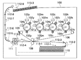
図1は、本発明の実施の形態に係る画像形成装置の構成図である。 FIG. 1 is a configuration diagram of an image forming apparatus according to an embodiment of the present invention.
同図において、装置本体100は以下の構成要素を備えている。以下、その構成要素を動作とともに説明する。
In FIG. 1, the apparatus
感光体101yは、反時計回りに回転していて、1次帯電ローラ102yは、感光体101yの表面を均一にマイナス帯電する。1次帯電ローラ102yは、感光体101yを均一に帯電するために、直流成分マイナス300Vからマイナス900Vの電圧に交流成分1300Vから2000Vが重畳されている。
The photoreceptor 101y rotates counterclockwise, and the
高圧発生装置は、通常、装置本体100内のモータ等を動作させるために使用する24V等の電圧を元にして、高圧トランスを用いてこれらの電圧を生成している場合が多い。
In many cases, the high-voltage generator generates these voltages using a high-voltage transformer based on a voltage of 24 V or the like that is usually used to operate a motor or the like in the apparatus
均一に帯電した感光体101yの表面に、レーザーユニット103yから照射されるレーザーが露光される。露光された部分は感光してインピーダンスが低下して帯電量が低下する。
A laser irradiated from the
レーザーユニット103yは、ON/OFF、PWM制御により露光量を制御していて、感光体101yの表面に帯電量の分布で潜像画像が描画される。
The
次に、現像スリーブ104yを感光体表面が通過する。この現像スリーブ104yと感光体101yの間のギャップは高精度に管理されている。現像スリーブ104yに、直流成分マイナス150V〜マイナス700Vと交流成分1000V〜2000Vの高圧を加えることで、感光体101yの表面と現像スリーブ104yの間に電界が発生する。
Next, the surface of the photoreceptor passes through the developing
これにおいても、帯電プロセス同様に、高圧トランスを用いた高圧発生装置により直流成分及び交流成分を生成しており、特に、現像プロセスでは交流成分の波形が画質に大きく影響する。 In this case as well, like the charging process, a DC component and an AC component are generated by a high-voltage generator using a high-voltage transformer. In particular, in the development process, the waveform of the AC component greatly affects the image quality.
この電界の向きと強度は帯電量に影響され、レーザーで露光されてないマイナス帯電量の大きい感光体101yの表面のところでは現像スリーブ104yから感光体101yに向かう電界が生じる。
The direction and intensity of the electric field is affected by the amount of charge, and an electric field is generated from the developing
一方、レーザーで強く露光されて感光体101yの表面の帯電量の小さいところでは、感光体101yから現像スリーブ104yに向かう電界が生じる。
On the other hand, an electric field is generated from the photoreceptor 101y toward the developing
現像スリーブ104y上のマイナスに帯電したイエローのトナーは、現像スリーブ104yと感光体101yの表面の電界の向きと反対方向に力を受ける。このことで、電界の向きと強弱により、先の帯電量によって形成された感光体101y上の潜像画像がイエローのトナーによって現像され、トナー像が形成される。
The negatively charged yellow toner on the developing
次に、感光体101yの表面は中間転写ベルト106と接する。中間転写ベルト106の感光体101yの反対側には1次転写ローラ105yがある。この1次転写ローラ105yには、プラス200V〜プラス1500Vの電圧が加えられていて、マイナスに帯電したイエローのトナーを感光体101yから1次転写ローラ105y側に引き寄せる。それにより、感光体101yの表面にあったイエローのトナーが中間転写ベルト106の表面に転写される。
Next, the surface of the photoconductor 101 y is in contact with the
同様にしてマゼンタ、シアン、ブラックのトナーが中間転写ベルト106の表面に転写される。感光体101y、1次帯電ローラ102y、レーザーユニット103y、現像スリーブ104y、1次転写ローラ105yに対応するマゼンタ、シアン、ブラックのユニットには、m、c、kが付されている。
Similarly, magenta, cyan, and black toners are transferred onto the surface of the
こうして、中間転写ベルト106には、イエローとマゼンタとシアンとブラックのトナーで形成されたフルカラーの画像が形成される。そして、中間転写ベルト106が2次転写内ローラ107と2次転写外ローラ108を通過する。その時に、中間転写ベルト106と2次転写外ローラ108の間を用紙113が挟まれて搬送される。
Thus, a full-color image formed with yellow, magenta, cyan, and black toners is formed on the
2次転写外ローラ108には、プラス500〜プラス7000Vの電圧が加えられていて、マイナスに帯電したトナーが、用紙113の上表面に転写される。用紙113は用紙カセット110から給紙されて、矢印112−1、112−2、112−3、112−4と搬送される。
A voltage of plus 500 to plus 7000 V is applied to the secondary transfer
2次転写内ローラ107と2次転写外ローラ108を通過した用紙113−2表面のトナーは未定着トナーで、用紙113−2から容易に剥がれる状態である。この状態の用紙113−2が定着器111に搬送されて高温にされ、トナーが柔らかくなったところで、圧力を加えられることで、トナーは、用紙113の表面に張り付き定着する。
The toner on the surface of the sheet 113-2 that has passed through the secondary transfer
そして、用紙113−3は、矢印112−5、112−6、112−7、112−8、112−9と搬送されて出力され積載される。定着器111としては、電磁誘導加熱方式を用いている。
Then, the sheet 113-3 is conveyed as arrows 112-5, 112-6, 112-7, 112-8, and 112-9, and is output and stacked. As the
図2は、図1における定着器の構成図である。 FIG. 2 is a configuration diagram of the fixing device in FIG.
図2において、ベルト(回転体)201は、厚さ45μmの導電性発熱体を含み、表面は300μmのゴム層で覆われている。ベルト201は駆動ローラ202との間でニップ部203を形成し、ベルト201は、駆動ローラ202の回転をニップ部203から伝えられることによって矢印方向に回転する。
In FIG. 2, a belt (rotating body) 201 includes a conductive heating element having a thickness of 45 μm, and the surface is covered with a rubber layer having a thickness of 300 μm. The
また、ベルト201に対向してコイル(第1の加熱手段)204がコイルホルダ205内に配置され、コイル204に交流電流を流して磁場を発生させることで、ベルト201の導電性発熱体が自己発熱する。コイル204は、高周波電力の印加により高周波磁界を発生させる誘導加熱コイルである。
Further, a coil (first heating means) 204 is disposed in the
サーミスタ(温度検出手段)206は、ベルト201の発熱部に内側から当接しており、その温度を検出している。
The thermistor (temperature detection means) 206 is in contact with the heat generating portion of the
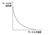
図3は、図2におけるサーミスタの温度と抵抗値の関係を示す図である。 FIG. 3 is a diagram illustrating the relationship between the temperature and resistance value of the thermistor in FIG.
サーミスタ206は、図3に示すように、温度が低いほど高い抵抗値となる抵抗体である。本定着器111は、サーミスタ206で検出される温度を目標の温度である180℃になるように、コイル204に流す交流電流を増減させている。
As shown in FIG. 3, the
図4は、本発明の第1の実施の形態に係る定着制御装置のブロック図である。 FIG. 4 is a block diagram of the fixing control apparatus according to the first embodiment of the present invention.
本定着制御装置は、定着器111と電源装置400とから構成される。電源装置400は、コイル204に交流電流を供給する。
The fixing control device includes a
電源装置400は、商用電源のような交流電源500に接続され、ダイオードブリッジ401、コンデンサ402、共振回路を形成する共振コンデンサ405、第1、第2のスイッチ素子403、404を備える。
The
また、電源装置400は、2つのスイッチ素子403、404を駆動信号421、422で駆動する駆動回路412、制御回路413、入力電力を検出する電力検出回路411を備える。
The
また、電源装置400は、サーミスタ206の検出温度が所定の過昇温レベル(所定の温度以上)に達しているかどうかを判断し、過昇温レベルに達した場合にコイル204への交流電流供給を強制的に停止させる過昇温検出回路414を備える。
Further, the
また、電源装置400は、サーミスタ206を加熱する加熱回路(第2の加熱手段)415を備える。制御回路413は、予め決められた最大電力の範囲内でベルト201の温度が目標温度になるように、電力検出回路411の検出結果及びサーミスタ206の検出結果によって、駆動信号421、422の周波数(駆動周波数)を変化させる。
The
スイッチ素子403と404は、駆動信号421、422に従って交互にON/OFFし、コイル204に高周波電流を供給する。コイル204に流す交流電流は、コイル204及びベルト201のインダクタンス値と共振コンデンサ405の容量値から決まる共振周波数よりも高い周波数で、駆動信号421、422の周波数を低くすると増加し、高くすると減少する。交流電流の増減は発生する磁場の強さの増減となり、導電性発熱体の発熱量の増減につながる。これによりベルト201の温度を制御することができる。
The
サーミスタ206は、ベルト201が回転している時と停止している時とで検出温度が所定の温度差以上になるように、加熱回路415で加熱される。
The
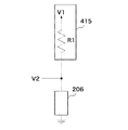
図5は、図4におけるサーミスタと加熱回路の第1の接続構成例を示す図である。 FIG. 5 is a diagram illustrating a first connection configuration example of the thermistor and the heating circuit in FIG. 4.
図5において、加熱回路415は、サーミスタ206と直列に接続される抵抗R1を有し、抵抗R1は、基準電圧V1に接続されている。抵抗R1は、サーミスタ206が210℃の時の抵抗値とほぼ同じ抵抗値4.3kΩにしている。基準電圧V1は20Vとしている。
In FIG. 5, the
本実施の形態では、加熱回路415は、サーミスタ206による温度検出信号を得るための基準電圧と分圧抵抗を生成している。
In the present embodiment, the
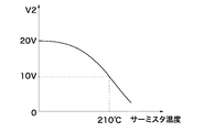
図6は、図4における過昇温検出回路の構成図、図7は、図5におけるサーミスタの温度と電圧V2の関係を示す図である。 6 is a block diagram of the overheat detection circuit in FIG. 4, and FIG. 7 is a diagram showing the relationship between the temperature of the thermistor and the voltage V2 in FIG.
過昇温検出回路414は、図6に示すように、V2と過昇温検出レベルV3とをコンパレータIC1で比較し、V2<V3となった場合に強制停止信号V4を“H”にする。V4が“H”になると、駆動回路412は、制御回路413からの信号に関わらず、スイッチ素子403と404の駆動を停止させる。これにより、交流電流の供給も停止し、発熱も停止する。
As shown in FIG. 6, the excessive temperature
サーミスタ206と接触しているベルト201は、回転時は次々と新たな領域がサーミスタ206の熱を奪うため、熱抵抗は25℃/Wに、停止時は熱伝導の悪さから熱抵抗は500℃/Wに相当する。
The
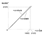
サーミスタ206は、210℃付近では約23mWの発熱があるため、ベルト回転時はほぼベルト温度と同じになるが、ベルト停止時はベルト201の温度に対してサーミスタ206の温度は約11℃高くなる。つまり、ベルト停止時は実際のベルト201の温度は199℃である時に、過昇温検出回路414が210℃を検出することとなる(図8参照)。
Since the
次に、本構成において異常昇温が発生した場合の保護動作について説明する。 Next, a protection operation when an abnormal temperature rise occurs in this configuration will be described.
図9は、ベルト201が回転している状態で異常昇温した場合の温度カーブを示す図である。
FIG. 9 is a diagram showing a temperature curve when the temperature rises abnormally while the
異常昇温発生時は、サーミスタ206への熱の伝達時間に対し、ベルト201の温度上昇がはるかに急速になることによって、サーミスタ206での検出は遅れを生じる。しかし、ベルト回転時はサーミスタ206への熱の伝達時間に対し比較的温度上昇も緩やかであり、周辺の部材にダメージを与える前に過昇温を検出している。
When the abnormal temperature rise occurs, the temperature rise of the
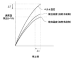
図10は、ベルト201が停止している状態で異常昇温した場合の温度カーブである。
FIG. 10 is a temperature curve when the temperature rises abnormally while the
ベルト201が停止している状態では、回転している状態に比べてベルト201の温度上昇速度が急速になるが、本発明の構成においては、前述したようにサーミスタ206によって検出される温度も従来のものより高くなる。
In the state where the
そのため、図中Δtだけ過昇温を検出する時間が早くなり、ベルト201の最高到達温度もΔTだけ低くできる。それによって、周辺の部材にダメージを与えるのを防ぐことができる。
For this reason, the time for detecting the excessive temperature rise is advanced by Δt in the figure, and the maximum temperature reached by the
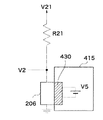
図11は、図4におけるサーミスタと加熱回路の第2の接続構成例を示す図である。 FIG. 11 is a diagram illustrating a second connection configuration example of the thermistor and the heating circuit in FIG.
図11において、加熱回路415は、ヒータ430とヒータ用電源V5から構成されている。更に、ヒータ430は、サーミスタ206に接している、または近傍に配置されており、ベルト回転時と停止時とで、図12に示すような検出温度差になるように、サーミスタ206を加熱している。
In FIG. 11, the
サーミスタ206と直列に抵抗R21が接続され、更に、抵抗R21は、基準電圧V21に接続されている。R21は4.3kΩ、V21は3.3Vである。
A resistor R21 is connected in series with the
図11の加熱回路415を採用しても、図5の加熱回路415と同様、ベルト回転時はほぼベルト温度と同じになるが、ベルト停止時はベルト201の温度に対してサーミスタ206の温度は約11℃高くなる。
Even if the
つまり、ベルト停止時は実際のベルト201の温度は199℃である時に、過昇温検出回路114が210℃を検出することとなる。従って、ベルト201が停止している状態で異常昇温した場合にも過昇温を早く検出でき、周辺の部材にダメージを与えるのを防ぐことができる。
That is, when the belt is stopped, the excessive temperature rise detection circuit 114 detects 210 ° C. when the actual temperature of the
図13は、本発明の第2の実施の形態に係る定着制御装置のブロック図である。 FIG. 13 is a block diagram of a fixing control apparatus according to the second embodiment of the present invention.
第2の実施の形態の定着制御装置は、図13に示すように、ベルト温度がほぼ同じ場所に近接して2つ(複数)のサーミスタ206a、206bが配置されている。そのうちサーミスタ206aのみ加熱回路415で、第1の実施の形態と同様に加熱している。
As shown in FIG. 13, in the fixing control device of the second embodiment, two (plural)
図14は、図13におけるサーミスタ206bの接続例を示す図である。
FIG. 14 is a diagram showing a connection example of the
サーミスタ206bと直列に抵抗R11が接続され、更に、抵抗R11は、基準電圧V11に接続されている。R11は4.3kΩ、V11は3.3Vである。そのため、サーミスタ206bで検出される温度は、ベルト201が回転していても停止していてもベルト201の温度と等しくなる。
A resistor R11 is connected in series with the
また、電源装置400には、サーミスタ206a、206bでの検出温度の差を検出する温度差検出回路416が実装されている。温度差検出回路416は、V2とV12の電位差が所定の差以上になった場合、つまりサーミスタ206a、206bでの検出温度の差が所定の温度差(この場合8℃)以上になった場合、ベルト201の回転が停止と判断する。そして、温度差検出回路416は、コイル204への交流電流の供給を停止させる。
In addition, a temperature difference detection circuit 416 that detects a difference in temperature detected by the
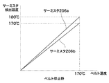
180℃にベルト201の温度を制御している場合に、ベルト201の回転が停止すると、図15に示す特性により、サーミスタ206aで検出した温度は、サーミスタ206bで検出した温度よりもおよそ10℃高くなる。従って、ベルト201が回転しているか停止しているかの判断が可能となる。
When the temperature of the
111 定着器
201 ベルト
202 駆動ローラ
203 ニップ
204 コイル
206 サーミスタ
400 電源装置
411 電力検出回路
412 駆動回路
413 制御回路
414 過昇温検出回路
415 加熱回路
416 温度差検出回路
111
Claims (4)
前記回転体を加熱する第1の加熱手段と、
前記回転体に当接し、前記回転体の温度を検出する温度検出手段と、
前記温度検出手段を加熱する第2の加熱手段と、
前記第1の加熱手段を駆動する駆動手段と、
前記温度検出手段の検出温度が所定の温度以上になった場合に、前記駆動手段を停止させる過昇温検出手段と、
前記温度検出手段の検出結果から前記駆動手段の駆動周波数を制御する制御手段とを備え、
前記温度検出手段は、前記回転体が回転している時と停止している時とで前記検出温度が所定の温度差以上になるように、前記第2の加熱手段で加熱されることを特徴とする定着制御装置。 A rotating body,
First heating means for heating the rotating body;
Temperature detecting means for contacting the rotating body and detecting the temperature of the rotating body;
Second heating means for heating the temperature detection means;
Driving means for driving the first heating means;
An excessive temperature rise detecting means for stopping the driving means when the temperature detected by the temperature detecting means is equal to or higher than a predetermined temperature;
Control means for controlling the drive frequency of the drive means from the detection result of the temperature detection means,
The temperature detecting means is heated by the second heating means so that the detected temperature is not less than a predetermined temperature difference between when the rotating body is rotating and when it is stopped. A fixing control device.
前記回転体を加熱する第1の加熱手段と、
前記回転体に当接し、前記回転体の温度を検出する複数の温度検出手段と、
前記複数の温度検出手段のうちの一方の温度検出手段を加熱する第2の加熱手段と、
前記第1の加熱手段を駆動する駆動手段と、
前記複数の温度検出手段の検出温度が所定の温度差以上になった場合に、前記駆動手段を停止させる温度差検出手段と、
前記温度検出手段の検出結果から前記駆動手段の駆動周波数を制御する制御手段とを備え、
前記一方の温度検出手段は、前記回転体が回転している時と停止している時とで、前記複数の温度検出手段の前記検出温度が前記所定の温度差以上になるように、前記第2の加熱手段で加熱されることを特徴とする定着制御装置。 A rotating body,
First heating means for heating the rotating body;
A plurality of temperature detecting means for contacting the rotating body and detecting the temperature of the rotating body;
A second heating means for heating one of the plurality of temperature detecting means;
Driving means for driving the first heating means;
A temperature difference detecting means for stopping the driving means when the detected temperature of the plurality of temperature detecting means is equal to or higher than a predetermined temperature difference;
Control means for controlling the drive frequency of the drive means from the detection result of the temperature detection means,
The one temperature detecting means is configured so that the detected temperature of the plurality of temperature detecting means is greater than or equal to the predetermined temperature difference between when the rotating body is rotating and when the rotating body is stopped. A fixing control device, wherein the fixing control device is heated by two heating means.
Priority Applications (2)
| Application Number | Priority Date | Filing Date | Title |
|---|---|---|---|
| JP2008294427A JP2010122360A (en) | 2008-11-18 | 2008-11-18 | Fixing controller and image forming apparatus |
| US12/618,439 US8023841B2 (en) | 2008-11-18 | 2009-11-13 | Fixing controller and image forming apparatus |
Applications Claiming Priority (1)
| Application Number | Priority Date | Filing Date | Title |
|---|---|---|---|
| JP2008294427A JP2010122360A (en) | 2008-11-18 | 2008-11-18 | Fixing controller and image forming apparatus |
Publications (2)
| Publication Number | Publication Date |
|---|---|
| JP2010122360A true JP2010122360A (en) | 2010-06-03 |
| JP2010122360A5 JP2010122360A5 (en) | 2012-01-12 |
Family
ID=42172153
Family Applications (1)
| Application Number | Title | Priority Date | Filing Date |
|---|---|---|---|
| JP2008294427A Pending JP2010122360A (en) | 2008-11-18 | 2008-11-18 | Fixing controller and image forming apparatus |
Country Status (2)
| Country | Link |
|---|---|
| US (1) | US8023841B2 (en) |
| JP (1) | JP2010122360A (en) |
Cited By (1)
| Publication number | Priority date | Publication date | Assignee | Title |
|---|---|---|---|---|
| JP2014010319A (en) * | 2012-06-29 | 2014-01-20 | Canon Inc | Fixing device and image forming apparatus |
Families Citing this family (3)
| Publication number | Priority date | Publication date | Assignee | Title |
|---|---|---|---|---|
| CN103219877B (en) * | 2012-01-20 | 2016-06-01 | 台达电子企业管理(上海)有限公司 | A kind of capacitor discharging circuit and changer |
| JP2014115510A (en) * | 2012-12-11 | 2014-06-26 | Canon Inc | Image-heating control device |
| JP2020022276A (en) * | 2018-07-31 | 2020-02-06 | 株式会社リコー | Power supply device and image forming apparatus |
Citations (10)
| Publication number | Priority date | Publication date | Assignee | Title |
|---|---|---|---|---|
| JPH0683236A (en) * | 1992-08-31 | 1994-03-25 | Minolta Camera Co Ltd | Heater controller for fixing roller |
| JPH0816029A (en) * | 1994-06-28 | 1996-01-19 | Toshiba Corp | Image forming apparatus |
| JPH10268694A (en) * | 1997-03-24 | 1998-10-09 | Canon Inc | Heating device, fixing device, and image forming device |
| JP2002372459A (en) * | 2001-06-13 | 2002-12-26 | Fuji Xerox Co Ltd | Temperature detector and fixing apparatus using the same |
| JP2005353460A (en) * | 2004-06-11 | 2005-12-22 | Fuji Xerox Co Ltd | Heating device |
| JP2006201625A (en) * | 2005-01-21 | 2006-08-03 | Ricoh Co Ltd | Fixing device and image forming apparatus provided with fixing device |
| JP2007147993A (en) * | 2005-11-28 | 2007-06-14 | Sharp Corp | Fixing device and image forming device |
| JP2007199595A (en) * | 2006-01-30 | 2007-08-09 | Canon Inc | Fixing device and image forming apparatus |
| JP2007264927A (en) * | 2006-03-28 | 2007-10-11 | Canon Inc | Signal processor, current detector, power controller and image forming apparatus with them |
| JP2008040401A (en) * | 2006-08-10 | 2008-02-21 | Konica Minolta Business Technologies Inc | Image forming apparatus |
Family Cites Families (9)
| Publication number | Priority date | Publication date | Assignee | Title |
|---|---|---|---|---|
| JPS5288033A (en) * | 1976-01-19 | 1977-07-22 | Fuji Xerox Co Ltd | Abnormal temperature detector for fixing apparatus |
| US4745430A (en) * | 1985-11-01 | 1988-05-17 | Casio Computer Co. Ltd. | Malfunction detecting device in use for the fixing device of an image-forming apparatus |
| JP2005024934A (en) | 2003-07-03 | 2005-01-27 | Fuji Xerox Co Ltd | Belt, fixing device and image forming apparatus |
| JP2005338698A (en) | 2004-05-31 | 2005-12-08 | Canon Inc | Image forming device |
| JP4594063B2 (en) * | 2004-12-20 | 2010-12-08 | キヤノン株式会社 | Image heating device |
| US7242880B2 (en) * | 2005-03-17 | 2007-07-10 | Kabushiki Kaisha Toshiba | Fixing apparatus and heating apparatus control method |
| JP2007086208A (en) * | 2005-09-20 | 2007-04-05 | Sharp Corp | Fixing device and image forming apparatus |
| JP4410199B2 (en) * | 2006-02-14 | 2010-02-03 | シャープ株式会社 | Fixing device |
| JP2007279636A (en) * | 2006-04-12 | 2007-10-25 | Toshiba Corp | Image forming apparatus |
-
2008
- 2008-11-18 JP JP2008294427A patent/JP2010122360A/en active Pending
-
2009
- 2009-11-13 US US12/618,439 patent/US8023841B2/en not_active Expired - Fee Related
Patent Citations (10)
| Publication number | Priority date | Publication date | Assignee | Title |
|---|---|---|---|---|
| JPH0683236A (en) * | 1992-08-31 | 1994-03-25 | Minolta Camera Co Ltd | Heater controller for fixing roller |
| JPH0816029A (en) * | 1994-06-28 | 1996-01-19 | Toshiba Corp | Image forming apparatus |
| JPH10268694A (en) * | 1997-03-24 | 1998-10-09 | Canon Inc | Heating device, fixing device, and image forming device |
| JP2002372459A (en) * | 2001-06-13 | 2002-12-26 | Fuji Xerox Co Ltd | Temperature detector and fixing apparatus using the same |
| JP2005353460A (en) * | 2004-06-11 | 2005-12-22 | Fuji Xerox Co Ltd | Heating device |
| JP2006201625A (en) * | 2005-01-21 | 2006-08-03 | Ricoh Co Ltd | Fixing device and image forming apparatus provided with fixing device |
| JP2007147993A (en) * | 2005-11-28 | 2007-06-14 | Sharp Corp | Fixing device and image forming device |
| JP2007199595A (en) * | 2006-01-30 | 2007-08-09 | Canon Inc | Fixing device and image forming apparatus |
| JP2007264927A (en) * | 2006-03-28 | 2007-10-11 | Canon Inc | Signal processor, current detector, power controller and image forming apparatus with them |
| JP2008040401A (en) * | 2006-08-10 | 2008-02-21 | Konica Minolta Business Technologies Inc | Image forming apparatus |
Cited By (1)
| Publication number | Priority date | Publication date | Assignee | Title |
|---|---|---|---|---|
| JP2014010319A (en) * | 2012-06-29 | 2014-01-20 | Canon Inc | Fixing device and image forming apparatus |
Also Published As
| Publication number | Publication date |
|---|---|
| US8023841B2 (en) | 2011-09-20 |
| US20100124429A1 (en) | 2010-05-20 |
Similar Documents
| Publication | Publication Date | Title |
|---|---|---|
| JP5424012B2 (en) | Fixing device control method, fixing device, and image forming apparatus | |
| EP4212964A1 (en) | Image forming apparatus | |
| US10990054B2 (en) | Image forming apparatus that corrects a target temperature for heating a region without a toner image when an abnormality is detected | |
| US12019384B2 (en) | Image forming apparatus that fixes toner image to recording medium using heater | |
| CN100507751C (en) | Fixing unit used with image forming device | |
| US20030091359A1 (en) | Power control method and apparatus for fusing roller of electrophotographic image forming apparatus | |
| JP5562132B2 (en) | Heating device and voltage detection circuit | |
| US6507008B2 (en) | Image forming apparatus and fixing device for fixing a toner image to a fixing device | |
| JP4047644B2 (en) | Fixing device | |
| JP2010122360A (en) | Fixing controller and image forming apparatus | |
| JP2009145386A (en) | Image forming apparatus | |
| JP5528194B2 (en) | Image forming apparatus | |
| JPH09197875A (en) | Fixing device and image forming device | |
| CN100410822C (en) | Heat generating device using electromagnetic induction | |
| JP2009053677A (en) | Fixing apparatus | |
| US11914315B2 (en) | Image forming apparatus that fixes toner image to recording medium using first and second heaters supplied with current during overlapping time periods | |
| JP2003122183A (en) | Fixing device and image forming apparatus | |
| US20230033004A1 (en) | Image forming apparatus | |
| JP4944417B2 (en) | Image forming apparatus | |
| KR20230014651A (en) | Image forming apparatus for controlling heater of fixing unit powered by two power sources | |
| JP5640103B2 (en) | Fixing apparatus and image forming apparatus | |
| JP2024155047A (en) | Fixing device and image forming apparatus | |
| JP2003282219A (en) | Heater and image forming device | |
| JPH10207286A (en) | Method for controlling temperature of material to be heated | |
| JP2007108329A (en) | Image forming apparatus |
Legal Events
| Date | Code | Title | Description |
|---|---|---|---|
| A521 | Written amendment |
Free format text: JAPANESE INTERMEDIATE CODE: A523 Effective date: 20111117 |
|
| A621 | Written request for application examination |
Free format text: JAPANESE INTERMEDIATE CODE: A621 Effective date: 20111117 |
|
| A977 | Report on retrieval |
Free format text: JAPANESE INTERMEDIATE CODE: A971007 Effective date: 20130212 |
|
| A131 | Notification of reasons for refusal |
Free format text: JAPANESE INTERMEDIATE CODE: A131 Effective date: 20130219 |
|
| A521 | Written amendment |
Free format text: JAPANESE INTERMEDIATE CODE: A523 Effective date: 20130419 |
|
| A02 | Decision of refusal |
Free format text: JAPANESE INTERMEDIATE CODE: A02 Effective date: 20131008 |
