JP2010120685A - Sterilizing bag, sterilizing bag body, and its manufacturing method - Google Patents

Sterilizing bag, sterilizing bag body, and its manufacturing method Download PDF

Info

Publication number
JP2010120685A
JP2010120685A JP2008297144A JP2008297144A JP2010120685A JP 2010120685 A JP2010120685 A JP 2010120685A JP 2008297144 A JP2008297144 A JP 2008297144A JP 2008297144 A JP2008297144 A JP 2008297144A JP 2010120685 A JP2010120685 A JP 2010120685A
Authority
JP
Japan
Prior art keywords
bag
sterilization
heat
breathable film
sterilization bag
Prior art date
Legal status (The legal status is an assumption and is not a legal conclusion. Google has not performed a legal analysis and makes no representation as to the accuracy of the status listed.)
Granted
Application number
JP2008297144A
Other languages
Japanese (ja)
Other versions
JP5277899B2 (en
Inventor
Takashi Asakura
隆 浅倉
Keigo Goto
啓吾 後藤
Current Assignee (The listed assignees may be inaccurate. Google has not performed a legal analysis and makes no representation or warranty as to the accuracy of the list.)
Dai Nippon Printing Co Ltd
Original Assignee
Dai Nippon Printing Co Ltd
Priority date (The priority date is an assumption and is not a legal conclusion. Google has not performed a legal analysis and makes no representation as to the accuracy of the date listed.)
Filing date
Publication date
Application filed by Dai Nippon Printing Co Ltd filed Critical Dai Nippon Printing Co Ltd
Priority to JP2008297144A priority Critical patent/JP5277899B2/en
Publication of JP2010120685A publication Critical patent/JP2010120685A/en
Application granted granted Critical
Publication of JP5277899B2 publication Critical patent/JP5277899B2/en
Expired - Fee Related legal-status Critical Current
Anticipated expiration legal-status Critical

Links

Images

Abstract

<P>PROBLEM TO BE SOLVED: To provide a sterilizing bag, a sterilizing bag body, and its manufacturing method, maintaining a sufficient ventilation amount and forming the bag body which is not easily broken even when it is exposed to a rapid pressure reduction. <P>SOLUTION: End portions of two rectangular non-permeable films having the same width and different lengths are overlapped with each other, or caused to meet each other at the ends with permeability on strip-like sterilizing paper the long side of which is the same as the width of the non-permeable films, and side edge portions of the sterilizing paper are fixed to the two non-permeable films. The longer one of the non-permeable films is bent so as to have an approximately J-shaped cross section and to cause the two non-permeable films to face each other. The side edge portions thereof are fixed so as to form the sterilizing bag. <P>COPYRIGHT: (C)2010,JPO&INPIT

Description

本発明は、医療用器具、医療品、微生物検査器具、食品容器等の器具、および容器のエチレンオキサイドガス滅菌用袋、滅菌用包装体、及びその製造方法に関する。   The present invention relates to a medical device, a medical product, a microbiological test device, a food container, and an ethylene oxide gas sterilization bag, a sterilization package, and a method for manufacturing the same.

従来、医療用器具等を収納する包装袋に用いられる滅菌用袋として、袋の一部に通気部分を備えたエチレンオキサイドガス(以下「EOG」と称する)滅菌用袋が知られている。この滅菌用袋は、シリンジ等の医療器具等を収納後、開口部をヒートシールにより密封されて包装体となり、滅菌釜内でEOGを用いた気体置換および脱気処理を受け、包装体内の気体をEOGガスと置換することにより、滅菌処理が施される。   Conventionally, an ethylene oxide gas (hereinafter referred to as “EOG”) sterilization bag having a ventilation portion in a part of the bag is known as a sterilization bag used for a packaging bag for storing medical instruments and the like. This sterilization bag contains a medical instrument such as a syringe, and the opening is sealed by heat sealing to form a package, which is subjected to gas replacement and deaeration treatment using EOG in the sterilization kettle. By substituting EOG gas for sterilization.

ここで、滅菌用袋の通気部分の部材として、微生物が通過できない機能を有する、いわゆる滅菌紙が、一般に使用されているが、この滅菌紙は非常に高価である。   Here, as a member of the ventilation portion of the sterilization bag, so-called sterilized paper having a function of preventing passage of microorganisms is generally used, but this sterilized paper is very expensive.

そこで、滅菌紙の使用量を少なく抑え、コスト的に優れたEOG滅菌用袋として、内面が熱接着性である非通気性材料をU字状に折り畳んでなる略筒状体の少なくとも一部に、短冊状の滅菌紙をヒートシールし、通気部分として、ミシン目、または、針孔等を設け、前記略筒状体の所定の縁部を熱接着してなる滅菌用袋が、提案されている(例えば、特許文献1参照)。   Therefore, as a bag for EOG sterilization that reduces the amount of sterilized paper used and is excellent in cost, at least a part of a substantially cylindrical body formed by folding a non-breathable material whose inner surface is thermally adhesive into a U shape. A sterilization bag is proposed in which strip-shaped sterilized paper is heat sealed, a perforation or a needle hole is provided as a ventilation portion, and a predetermined edge of the substantially cylindrical body is thermally bonded. (For example, refer to Patent Document 1).

図13に、従来の滅菌用袋からなる滅菌用包装体の概略図を示す。ここで、(a)は平面図、(b)は図13(a)のD−D線で示した部分の断面図である。   FIG. 13 shows a schematic view of a sterilization package comprising a conventional sterilization bag. Here, (a) is a plan view and (b) is a cross-sectional view of the portion indicated by the line DD in FIG. 13 (a).

従来の滅菌用袋は以下のように作成される。まず、非通気性フィルムをロール状に巻き取った巻取り状原反から、非通気性フィルムを帯状に引き出し、その長手方向に連続して、ミシン目、または針孔等の孔を非通気性フィルムに設け、その孔を塞ぐように非通気性フィルムの内面側に帯状の滅菌紙をあてがって、滅菌紙両端を縦ヒートシールにより非通気性フィルムの内面に固定した後、非通気性フィルムを長手方向の中心線で折り曲げ、非通気性フィルムの両端を重ね合わせて縦ヒートシールを施し、更に、横ヒートシールにより幅方向と平行に周縁ヒートシール部を形成してからノッチを設け、裁断して滅菌用包装袋とする。
その後に、前記滅菌用袋を包装機にセットし、内容物を収納後、開口部にヒートシールを施して密封ヒートシール部を設け、滅菌用包装体とするものである。
A conventional sterilization bag is prepared as follows. First, the non-breathable film is wound in a roll shape, and then the non-breathable film is drawn into a strip shape, and the perforations or needle holes are continuously non-breathable in the longitudinal direction. A strip of sterilized paper is applied to the inner surface of the non-breathable film so as to close the hole, and both ends of the sterilized paper are fixed to the inner surface of the non-breathable film by vertical heat sealing. Bend at the center line in the longitudinal direction, overlap the both ends of the non-breathable film and apply vertical heat seal, and further form a peripheral heat seal part parallel to the width direction by horizontal heat seal, then provide a notch and cut Use sterilization packaging bags.
Thereafter, the sterilization bag is set in a packaging machine, and after the contents are stored, the opening is heat-sealed to provide a hermetic heat-sealing portion to obtain a sterilization package.

実開昭57−63081号公報Japanese Utility Model Publication No. 57-63081

しかしながら、従来の滅菌用包装体においては、各通気孔の開口面積が小さいため、包装体の通気量を確保するためには、ミシン目、または針孔を滅菌用袋の長手方向に多く設ける必要があり、自ずと短冊状の滅菌紙の配置も滅菌用袋の長手方向に配置せねばならず、結果的に高価な滅菌紙の使用量が多くなり、コスト上問題がある。   However, in the conventional sterilization packaging body, since the opening area of each ventilation hole is small, it is necessary to provide a large number of perforations or needle holes in the longitudinal direction of the sterilization bag in order to ensure the ventilation amount of the packaging body. Therefore, the strip-shaped sterilized paper must also be arranged in the longitudinal direction of the sterilization bag. As a result, the amount of expensive sterilized paper used is increased, resulting in a cost problem.

ここで、ミシン目や針孔の数を多くすれば、通気孔の総開口面積は大きくなるが、包装体が急激に膨張した際に、前記ミシン目、または針孔を設けた箇所で非通気性フィルムが破れ易くなり、このことにより滅菌紙も破損してしまうので、ミシン目、または針孔の数は少なくせざるを得ない。また、孔を大きくして数を少なくすることも可能だが、滅菌紙が白色であるため、孔から侵入して滅菌紙上に付着した異物が非常に目立ってしまう上、開封時に外に飛び出す危険性があるため、孔を大きくすることは好ましくない。
このため、従来の滅菌用包装体においては、ミシン目や針孔の数を多くする手法も、各孔を大きくする手法も、採用することは困難であり、EOG滅菌処理における気体置換には、長い時間を要することになり、EOG滅菌処理の能率低下を招いている。
Here, if the number of perforations and needle holes is increased, the total opening area of the vent holes becomes large. However, when the packaging body expands rapidly, the perforations or portions where the needle holes are provided are not vented. Since the permeable film is easily torn and the sterilized paper is also damaged by this, the number of perforations or needle holes must be reduced. Although the number of holes can be increased to reduce the number, the sterilized paper is white, so foreign matter that enters through the holes and adheres to the sterilized paper is very noticeable, and there is a risk of popping out when opened. Therefore, it is not preferable to enlarge the hole.
For this reason, in the conventional sterilization package, it is difficult to adopt a method for increasing the number of perforations and needle holes and a method for enlarging each hole. For gas replacement in the EOG sterilization treatment, A long time is required, which leads to a decrease in efficiency of the EOG sterilization treatment.

また、袋体の開口部は短辺側に設けることが、一般的である。この理由は、密封ヒートシールが容易となること、及び、袋体の開口部を密封ヒートシールする際には、密封ヒートシール部周辺のスペースに余裕を持たせ、内容物がヒートシールバーと接触しないようにする必要があり、もし長辺側に開口部を設けてしまうと、袋体を大きく作らなければならず、コスト上の問題が生ずるためである。   Moreover, it is common to provide the opening part of a bag body in a short side. The reason for this is that sealing heat sealing becomes easy, and when sealing and heat-sealing the opening of the bag body, allow space in the space around the sealing heat-sealing part, and the contents come into contact with the heat-seal bar. This is because if the opening is provided on the long side, the bag must be made large, resulting in a cost problem.

それゆえ、滅菌用袋においても同様に、開口部は滅菌用袋の短辺側に設けられるが、この場合、従来の滅菌用袋では、滅菌紙を挟み込んで密封ヒートシールせざるを得ないこととなる。   Therefore, similarly, in the sterilization bag, the opening is provided on the short side of the sterilization bag. In this case, in the conventional sterilization bag, sterilization paper is sandwiched and hermetically sealed and heat sealed. It becomes.

ここで、製袋機であれば、滅菌紙を挟みこんでヒートシールを施しても、袋体を構成するフィルムに張力が掛かった状態でヒートシールしたり、冷却したりできるため、ヒートシールすることが可能であるが、包装機においては、密封ヒートシール部に掛かる張力はほとんど無く、熱間ヒートシール強度が非常に低い滅菌紙を挟み込んでヒートシールすることは大変困難である。   Here, if it is a bag making machine, even if heat sealing is performed by sandwiching sterilized paper, the film constituting the bag body can be heat sealed or cooled in a state where tension is applied, so heat sealing is performed. However, in the packaging machine, there is almost no tension applied to the sealed heat seal part, and it is very difficult to heat seal by sandwiching sterilized paper having a very low hot heat seal strength.

一方、包装機において、ヒートシール部を冷却する機構を設けることは、ヒートシール部に生じるたるみ、または収縮等から困難が伴う。
したがって、包装機で開口部をヒートシールする際は、可能な限り高温でヒートシールせざるを得ず、そのため密封ヒートシール部のフィルムが損傷を受け易く、滅菌時の急激な減圧で包装体が膨張した際に、従来の滅菌用包装体においては、上記理由により、密封ヒートシール部で破袋し易く、かつ、回避することは非常に困難であった。
On the other hand, in a packaging machine, it is difficult to provide a mechanism for cooling the heat seal part because of slack or shrinkage that occurs in the heat seal part.
Therefore, when heat-sealing the opening with a packaging machine, it must be heat-sealed at as high a temperature as possible, so that the film of the sealed heat-sealed part is easily damaged, and the package body is damaged by rapid decompression during sterilization. When inflated, the conventional sterilization packaging body is easily broken at the sealed heat-sealed portion and very difficult to avoid for the above reasons.

本発明は上記事情に対処してなされたものであり、包装機において滅菌紙を挟み込むことなく密封ヒートシールすることができ、充分な通気量を保持することができ、急激な減圧に晒されても破袋し難い滅菌用包装体を形成可能な滅菌用袋であって、かつ、袋毎の滅菌紙の使用量を少なくすることによりコスト面でも優れた滅菌用袋、滅菌用包装体、及びその製造方法を提供することを目的とするものである。   The present invention has been made in view of the above circumstances, can be sealed and heat sealed without sandwiching sterilized paper in a packaging machine, can maintain a sufficient amount of ventilation, and is exposed to rapid decompression. Is a sterilization bag capable of forming a sterilization package that is difficult to break, and the sterilization bag, the sterilization package, which are excellent in cost by reducing the amount of sterilized paper used for each bag, and The object is to provide a manufacturing method thereof.

本発明の請求項1に係る発明は、非通気性フィルムと滅菌紙からなる滅菌用袋において、同一幅で長さが異なる2枚の矩形状の非通気性フィルムの端部を、長辺が前記非通気性フィルムの幅と同一の短冊状の滅菌紙の上で、通気性を持たせて重ね合わせ、または合掌合わせし、前記滅菌紙の側縁部を前記2枚の非通気性フィルムに固定し、前記非通気性フィルムの長い方の1枚を断面略J字状に折り曲げて2枚の非通気性フィルムを対向させ、側縁部を固定して袋状に形成したことを特徴とする滅菌用袋である。   The invention according to claim 1 of the present invention is a sterilization bag made of a non-breathable film and sterilized paper, and has an end portion of two rectangular non-breathable films having the same width and different lengths. On the same strip-shaped sterilized paper having the same width as the non-breathable film, the two sheets of non-breathable film are laid on the side edges of the sterilized paper with the breathability. It is fixed, and the longer one of the non-breathable films is folded into a substantially J-shaped cross section so that the two non-breathable films face each other, and the side edges are fixed to form a bag. This is a sterilization bag.

また、本発明の請求項2に係る発明は、前記非通気性フィルムが、支持基材層と、少なくとも内面側に、ヒートシール性樹脂層とを積層してなる非通気性フィルムであることを特徴とする、請求項1に記載の滅菌用袋である。   The invention according to claim 2 of the present invention is that the non-breathable film is a non-breathable film formed by laminating a support base material layer and a heat-sealable resin layer at least on the inner surface side. The sterilization bag according to claim 1, characterized in that it is a feature.

また、本発明の請求項3に係る発明は、前記非通気性フィルムが、支持基材層の両面に、互いにヒートシール可能なヒートシール性樹脂層を積層してなる非通気性フィルムであることを特徴とする、請求項2に記載の滅菌用袋である。   In the invention according to claim 3 of the present invention, the non-breathable film is a non-breathable film formed by laminating heat-sealable resin layers that can be heat-sealed to each other on both sides of the support base material layer. The sterilization bag according to claim 2, wherein

また、本発明の請求項4に係る発明は、前記滅菌用袋において、前記滅菌紙の長辺側の固定部間を橋渡しする態様で、破袋防止ヒートシール部が、少なくとも一箇所に、形成されていることを特徴とする、請求項2または請求項3に記載の滅菌用袋である。   Moreover, the invention according to claim 4 of the present invention is an aspect in which, in the sterilization bag, the fixing part on the long side of the sterilized paper is bridged, and the bag breaking prevention heat seal part is formed in at least one place. The sterilization bag according to claim 2 or 3, wherein the bag is sterilized.

また、本発明の請求項5に係る発明は、前記滅菌用袋において、断面略J字状に折り曲げた部分を、滅菌用袋の内側に折り込んで片ガゼット袋状としたことを特徴とする、請求項1〜4のいずれかに記載の滅菌用袋である。   Further, the invention according to claim 5 of the present invention is characterized in that, in the sterilization bag, a portion folded into a substantially J-shaped cross section is folded inside the sterilization bag to form a one-gusset bag. It is a sterilization bag in any one of Claims 1-4.

また、本発明の請求項6に係る発明は、前記滅菌用袋の側縁部間の内寸法が、該滅菌用袋の底部と開口部を結ぶ寸法よりも短く、かつ、前記滅菌紙の長辺側の固定部が、該滅菌用袋の中心から、該滅菌用袋の側縁部間の内寸法を直径とする円領域の外側に位置することを特徴とする、請求項1〜5のいずれかに記載の滅菌用袋である。   In the invention according to claim 6 of the present invention, the inner dimension between the side edges of the sterilization bag is shorter than the dimension connecting the bottom and the opening of the sterilization bag, and the length of the sterilization paper is long. The side-side fixing part is located outside the circular region having the inside dimension between the side edges of the sterilization bag as a diameter from the center of the sterilization bag. The sterilization bag according to any one of the above.

また、本発明の請求項7に係る発明は、請求項1〜6のいずれかに記載の滅菌用袋に内容物を収納し、前記滅菌用袋の開口部を密封して形成したことを特徴とする、滅菌用包装体である。   The invention according to claim 7 of the present invention is characterized in that the contents are stored in the sterilization bag according to any one of claims 1 to 6 and the opening of the sterilization bag is sealed. And a sterilization package.

また、本発明の請求項8に係る発明は、非通気性フィルムと滅菌紙からなる滅菌用袋の製造方法において、支持基材層とヒートシール性樹脂層からなる帯状の非通気性フィルムを、ヒートシール性樹脂層が内面側になるように、幅方向の中心からの距離が異なる2箇所の位置で、長手方向と平行に折り曲げて、両端部を、通気性を持たせて重ね合わせ、または合掌合わせして略筒状とし、前記重ね合わせ部、または合掌合わせ部の内面側に、幅狭の帯状の滅菌紙をあてがい、前記滅菌紙の長手方向の両側縁部と非通気性フィルムの内面とを、連続的にヒートシールして前記滅菌紙を前記非通気性フィルムに固定し、かつ、前記非通気性フィルムに幅方向と平行なヒートシールを一定間隔で施して、前記滅菌用袋の周縁ヒートシール部を形成し、その後、前記非通気性フィルムの2箇所の折り曲げ部の片方を長手方向に切断して、前記滅菌用袋の開口部を形成し、さらに、前記非通気性フィルムに設けられた周縁ヒートシール部を幅方向に裁断して、前記滅菌用袋を製造することを特徴とする、滅菌用袋の製造方法である。   Further, the invention according to claim 8 of the present invention is a method for producing a sterilization bag comprising a non-breathable film and sterilized paper, and a strip-like non-breathable film comprising a support base material layer and a heat-sealable resin layer, Folded in parallel with the longitudinal direction at two positions with different distances from the center in the width direction so that the heat-sealable resin layer is on the inner surface side, and both ends are overlapped with air permeability, or Combined palms into a substantially cylindrical shape, apply narrow band-shaped sterilized paper on the inner surface side of the overlapped part or the palmed joint part, both side edges in the longitudinal direction of the sterilized paper, and the inner surface of the non-breathable film The sterilization paper is fixed to the non-breathable film by continuously heat-sealing, and the non-breathable film is heat-sealed parallel to the width direction at regular intervals, Form a peripheral heat seal Thereafter, one of the two bent portions of the non-breathable film is cut in the longitudinal direction to form an opening of the sterilization bag, and a peripheral heat seal portion provided on the non-breathable film is further provided. A method for producing a sterilization bag, wherein the sterilization bag is produced by cutting in the width direction.

また、本発明の請求項9に係る発明は、前記滅菌用袋の製造方法において、前記滅菌紙の長手方向の両側縁部と前記非通気性フィルムの内面とを、連続的にヒートシールして滅菌紙を非通気性フィルムに固定する際に、さらに、前記滅菌紙の長手方向の両側縁部のヒートシール間を橋渡しする態様で、前記非通気性フィルムにヒートシールを施して、破袋防止ヒートシール部を、少なくとも一箇所に形成することを特徴とする、請求項8に記載の滅菌用袋の製造方法である。   Further, the invention according to claim 9 of the present invention is the method for manufacturing a sterilization bag, wherein both the side edges in the longitudinal direction of the sterilized paper and the inner surface of the air-impermeable film are continuously heat-sealed. When fixing the sterilized paper to the non-breathable film, in addition to bridging between the heat seals at both side edges in the longitudinal direction of the sterilized paper, the non-breathable film is heat sealed to prevent bag breaking The method for producing a sterilization bag according to claim 8, wherein the heat seal part is formed at least at one place.

また、本発明の請求項10に係る発明は、前記滅菌用袋の製造方法において、前記非通気性フィルムが、支持基材層の両面に、互いにヒートシール可能なヒートシール性樹脂層を積層してなる非通気性フィルムであることを特徴とする、請求項9に記載の滅菌用袋の製造方法である。   The invention according to claim 10 of the present invention is the method for producing a sterilization bag, wherein the non-breathable film is formed by laminating heat-sealable resin layers heat-sealable on both sides of a support base material layer. The sterilization bag manufacturing method according to claim 9, wherein the sterilization bag is a non-breathable film.

また、本発明の請求項11に係る発明は、前記滅菌用袋の製造方法において、前記非通気性フィルムを折り曲げて両端部を重ね合わせ、または合掌合わせして略筒状とした後に、円盤状の回転するプレートを前記折り曲げ部の片方にあてがい、ガゼット部を形成することを特徴とする、請求項7〜9のいずれかに記載の滅菌用袋の製造方法である。   Further, the invention according to claim 11 of the present invention is the method for producing a sterilization bag, wherein the non-breathable film is folded and overlapped at both ends or joined together to form a substantially cylindrical shape, and then a disc shape. The sterilization bag manufacturing method according to claim 7, wherein the rotating plate is applied to one of the bent portions to form a gusset portion.

本発明に係る滅菌用袋においては、非通気性フィルムを滅菌紙の上で重ね合わせ、または合掌合わせにする構成により、従来の滅菌用袋に比べ、滅菌紙と非通気性フィルムとの間に異物が侵入しづらい点は同等以上で、かつ、滅菌紙の使用量が少ないにもかかわらず、通気用の開口面積は非常に大きくなる。したがって、本発明に係る滅菌用袋から製造した滅菌用包装体は、異物侵入防止の効果を保持しつつも、通気量を多く取れ、EOG滅菌時の急激な減圧に晒されても極度に膨張することは抑制され、破袋し難くなる効果を奏する。そして、袋毎の滅菌紙の使用量が少ないため、コスト面でも優れている。   In the sterilization bag according to the present invention, the non-breathable film is overlapped on the sterilized paper or the palms are joined together, so that the sterilization bag is placed between the sterilized paper and the non-breathable film as compared with the conventional sterilization bag. Despite the fact that foreign matter is less likely to penetrate and the amount of sterilized paper used is small, the opening area for ventilation becomes very large. Therefore, the sterilization package manufactured from the sterilization bag according to the present invention can take a large amount of airflow while maintaining the effect of preventing the intrusion of foreign matter, and can be extremely expanded even when exposed to a rapid decompression during EOG sterilization. Doing so is suppressed, and it has the effect of making it difficult to break the bag. And since there is little usage-amount of the sterilization paper for every bag, it is excellent also in terms of cost.

また、本発明に係る滅菌用袋においては、包装機において滅菌紙を挟み込むことなく密封ヒートシールすることができるため、従来の滅菌用袋のような高温ヒートシールは不要であり、非通気性フィルムに損傷は生じ難い。それゆえ、本発明に係る滅菌用袋から製造した滅菌用包装体は、EOG滅菌時に密封ヒートシール部で破袋するという不具合を防止することができる。   Further, in the sterilization bag according to the present invention, since it can be sealed and heat sealed without sandwiching sterilized paper in the packaging machine, a high temperature heat seal like a conventional sterilization bag is unnecessary, and a non-breathable film Damage is unlikely to occur. Therefore, the sterilization package manufactured from the sterilization bag according to the present invention can prevent a problem that the sealed heat seal part breaks the bag during EOG sterilization.

また、本発明に係る滅菌用袋においては、滅菌紙が表面に露出していないため、他の物質や液体等との接触による滅菌紙の汚染は生じ難く、衛生的にも優れるものである。   In the sterilization bag according to the present invention, since the sterilized paper is not exposed on the surface, the sterilized paper is hardly contaminated by contact with other substances or liquids, and is excellent in hygiene.

さらに、本発明に係る滅菌用袋に前記破袋防止ヒートシールを設ければ、本発明に係る滅菌用袋から製造した滅菌用包装体が膨張することによる滅菌紙の破損を防止することができる。   Furthermore, if the bag-breaking prevention heat seal is provided in the sterilization bag according to the present invention, it is possible to prevent the sterilization paper from being damaged by the expansion of the sterilization package manufactured from the sterilization bag according to the present invention. .

さらに、本発明に係る滅菌用袋は、片ガゼット袋とすることによって、より大きな内容物の収納にも対応できることになり、さらには自立性を付与することもできる。   Furthermore, the sterilization bag according to the present invention can be accommodated for storing larger contents by making it a one-piece gusset bag, and can also provide independence.

以下、図面を参照しながら本発明について、実施の形態を詳述する。
(第1の実施形態)
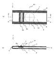
図1は、本発明に係る滅菌用袋の第1の実施形態の一例を示す概略図であり、(a)は平面図であり、(b)は図1(a)のA−A線における断面図である。
第1の実施形態における本発明の滅菌用袋1は、非通気性フィルム2を滅菌紙5の上で密封せずに重ね合わせることにより、異物の侵入を防ぎながら、通気面積を大きく取ることができる滅菌用袋である。
Hereinafter, embodiments of the present invention will be described in detail with reference to the drawings.
(First embodiment)
FIG. 1 is a schematic view showing an example of a first embodiment of a sterilization bag according to the present invention, (a) is a plan view, and (b) is taken along line AA in FIG. 1 (a). It is sectional drawing.
The sterilization bag 1 of the present invention in the first embodiment can take a large ventilation area while preventing the intrusion of foreign matter by superimposing the non-breathable film 2 on the sterilized paper 5 without sealing. A sterilization bag that can be used.

図1(a)、及び(b)に示すように、前記滅菌用袋1においては、非通気性フィルム2が折り曲げ部3で折り曲げられており、重ね合わせ部4で非通気性フィルム2同士が密封されずに重なっており、周縁ヒートシール部7で袋の両側縁がヒートシールされており、折り曲げ部3とは反対側に開口部9が設けられており、開口部9の近くの周縁ヒートシール部7にノッチ8が設けられている。   As shown in FIGS. 1 (a) and 1 (b), in the sterilization bag 1, the non-breathable film 2 is folded at the folding portion 3, and the non-breathable films 2 are formed at the overlapping portion 4. It overlaps without being sealed, and both side edges of the bag are heat-sealed by the peripheral heat seal part 7, and an opening 9 is provided on the side opposite to the bent part 3, and the peripheral heat near the opening 9 A notch 8 is provided in the seal portion 7.

前記滅菌用袋1の内部では、固定ヒートシール部6a、6bで短冊状の滅菌紙5の長辺側の両側縁部がヒートシールにより非通気性フィルム2に固定されている。   Inside the sterilization bag 1, both side edges on the long side of the strip-shaped sterilized paper 5 are fixed to the non-breathable film 2 by heat sealing at the fixed heat seal portions 6a and 6b.

重ね合わせ部4における、非通気性フィルム2同士が重なり合う幅は、狭すぎると異物が入り込み易くなり、広すぎると充分な通気量が得られなくなる。それゆえ、この重なり合う幅は、滅菌用袋1の大きさ、滅菌紙5の通気部分の幅、非通気性フィルム2の柔軟性、および滅菌時の減圧速度等を勘案して決められるが、通常は3mm〜25mm、好ましくは5mm〜15mmの範囲で形成される。   If the width at which the non-breathable films 2 overlap in the overlapping portion 4 is too narrow, foreign matter is likely to enter, and if it is too wide, a sufficient amount of ventilation cannot be obtained. Therefore, the overlapping width is determined in consideration of the size of the sterilization bag 1, the width of the ventilation portion of the sterilized paper 5, the flexibility of the non-breathable film 2, the decompression speed during sterilization, etc. Is formed in the range of 3 mm to 25 mm, preferably 5 mm to 15 mm.

滅菌紙5の固定ヒートシール部6a、6bの間の距離は、広いほど通気量が増え、EOG滅菌時の急激な減圧に対し、より耐性を有することになるが、徒に広くしても無駄であり、滅菌用袋1の内容積や、減圧速度等を勘案して決められる。通常は5mm〜40mm、好ましくは10mm〜20mmで形成される。   The wider the distance between the fixed heat seal portions 6a and 6b of the sterilized paper 5, the greater the air flow rate and the more resistant to sudden pressure reduction during EOG sterilization. It is determined in consideration of the internal volume of the sterilization bag 1 and the decompression speed. Usually, it is formed with 5 mm to 40 mm, preferably 10 mm to 20 mm.

固定ヒートシール部6a、6bの幅は、滅菌紙5と非通気性フィルム2とのヒートシール強度により左右されるが、通常は2mm〜20mm、好ましくは4mm〜10mmの範囲で形成される。なお、中心寄り固定ヒートシール部6aと、端寄り固定ヒートシール部6bの幅は同一でなくても構わないが、外観、およびヒートシール時の圧力のバランスを考えると、同一の幅であることが好ましい。   The widths of the fixed heat seal portions 6a and 6b depend on the heat seal strength between the sterilized paper 5 and the non-breathable film 2, but are usually 2 mm to 20 mm, preferably 4 mm to 10 mm. The widths of the center-side fixed heat seal portion 6a and the end-side fixed heat seal portion 6b may not be the same, but considering the appearance and the balance of pressure during heat sealing, the width is the same. Is preferred.

ヒートシールの方法としては、例えば、バーシール、回転ロールシール、ベルトシール、インパルスシール、高周波シール、超音波シール等の方法で行うことができる。
本発明に係る滅菌用袋1においては、非通気性フィルム2のヒートシール面と滅菌紙5との接着強度が3N/15mm以上であることが、包装、殺菌、流通の段階で意図に反する剥離が起こり難いため、好ましい。
Examples of the heat sealing method include a bar seal, a rotary roll seal, a belt seal, an impulse seal, a high frequency seal, and an ultrasonic seal.
In the sterilization bag 1 according to the present invention, the adhesive strength between the heat-sealed surface of the non-breathable film 2 and the sterilized paper 5 is 3N / 15 mm or more. Is preferable because it is difficult to occur.

周縁ヒートシール部7の幅は、強度保持と内容物収納のバランスから、通常は3mm〜15mm、好ましくは6mm〜12mmの範囲で形成される。なお、このヒートシールの幅とは、ベタシールの幅を示すのみならず、複数の線シールにより形成される1本のヒートシール部の外寸も含む。特に、滅菌紙5と非通気性フィルム2とのヒートシール強度が低い場合、ヒートシール部を複数の線シールにより形成し、ヒートシール圧を上げることで、滅菌紙5と非通気性フィルム2とのヒートシール性を向上させたり、滅菌紙5を挟み込んでヒートシールする箇所の、滅菌紙5端面のシール抜けを防止するのに役立つ。   The width of the peripheral heat seal part 7 is usually in the range of 3 mm to 15 mm, preferably 6 mm to 12 mm, from the balance of strength retention and content storage. The width of the heat seal indicates not only the width of the solid seal but also includes the outer dimension of one heat seal portion formed by a plurality of line seals. In particular, when the heat seal strength between the sterilized paper 5 and the non-breathable film 2 is low, the sterilized paper 5 and the non-breathable film 2 are formed by forming the heat seal portion with a plurality of line seals and increasing the heat seal pressure. This is useful for improving the heat sealability of the sterilized paper 5 and preventing the sterilized paper 5 from being unsealed at the end where the sterilized paper 5 is sandwiched and heat sealed.

図2は、前記滅菌用袋に内容物を収納し、密封ヒートシールを施した滅菌用包装体の一例を示す概略図である。
本発明に係る滅菌用包装体30は、図2に示すように、本発明に係る滅菌用袋1に内容物Mを開口部9から収納した後、開口部9近傍をヒートシールして密封ヒートシール部12を設けることにより形成される。
FIG. 2 is a schematic view showing an example of a sterilization package in which contents are stored in the sterilization bag and hermetically sealed.
As shown in FIG. 2, the sterilization package 30 according to the present invention stores the contents M from the opening 9 in the sterilization bag 1 according to the present invention, and then heat-seals the vicinity of the opening 9 to seal heat. It is formed by providing the seal portion 12.

本発明に係る滅菌用袋1は、重ね合わせ部4の未シール部分全体から気体の出入りが可能である。そのため、前記滅菌用袋1から形成した滅菌用包装体30は、EOG滅菌時の急激な減圧処理においても充分な通気量を得ることができ、包装体の膨張は生じ難く、それゆえ破袋し難いという効果を奏する。   The sterilization bag 1 according to the present invention allows gas to enter and exit from the entire unsealed portion of the overlapping portion 4. Therefore, the sterilization packaging body 30 formed from the sterilization bag 1 can obtain a sufficient amount of ventilation even in a rapid decompression process during EOG sterilization, and the expansion of the packaging body is unlikely to occur. The effect is difficult.

また、滅菌紙5の通気部分は重ね合わせ部7に覆われているため、滅菌紙5に外部からの異物が付着し難いという効果も得られ、衛生上好ましい。   Moreover, since the ventilation | gas_flowing part of the sterilization paper 5 is covered with the overlap part 7, the effect that the foreign material cannot adhere to the sterilization paper 5 easily is acquired, and it is preferable on hygiene.

さらに、本発明に係る滅菌用包装体30では、密封ヒートシール部12は非通気性フィルム2同士がヒートシールされるため、滅菌紙5を挟み込んで密封ヒートシール部12が設けられる従来の滅菌用袋32と比較して、容易にヒートシールを施すことができ、かつ、破袋強度の点で優れた密封ヒートシール部12を形成することができる。   Furthermore, in the sterilization package 30 according to the present invention, the sealed heat seal part 12 is heat-sealed between the non-breathable films 2, so that the sealed heat seal part 12 is provided by sandwiching the sterilized paper 5. Compared with the bag 32, heat sealing can be easily performed, and the sealed heat sealing part 12 excellent in terms of bag breaking strength can be formed.

また、中心寄り固定ヒートシール部6aを、図1において一点鎖線で示した、滅菌用袋の開口部9と折り曲げ部3との中間を示す中心線51よりも折り曲げ部3に近い側に配置することにより、滅菌時の急激な減圧処理で滅菌用袋1からなる滅菌用包装体30が膨張しても、中心寄り固定ヒートシール部6aは、膨張により最も破袋の力を受ける中心点を通る中心線51より端寄りに位置するため、滅菌紙5の部分での破袋をより抑えることができ、好ましい。   Further, the center-side fixed heat seal portion 6a is disposed on the side closer to the bent portion 3 than the center line 51, which is shown by a one-dot chain line in FIG. 1 and shows the middle between the opening 9 and the bent portion 3 of the sterilization bag. Thus, even if the sterilization package 30 including the sterilization bag 1 expands due to a rapid decompression process during sterilization, the center-fixed heat seal portion 6a passes through the center point that receives the force of the bag breaking most due to the expansion. Since it is located closer to the end than the center line 51, bag breakage at the portion of the sterilized paper 5 can be further suppressed, which is preferable.

更に、図1において点線で示した、滅菌用袋1の中心を円の中心とし、両周縁ヒートシール部7間の内寸法を直径とする円52の外側に中心寄り固定ヒートシール部6aを配置すれば、より破袋強度が増すため、より好ましい。   Further, a center-fixed heat seal portion 6a is disposed outside a circle 52 having the center of the circle as the center of the sterilization bag 1 shown in FIG. This is more preferable because the bag breaking strength is further increased.

なお、この場合必然的に、両周縁ヒートシール部7間の内寸法は、周縁ヒートシール部7の開口部9から折り曲げ部3までの長さの寸法よりも短くなることになる。   In this case, the inner dimension between the peripheral heat seal portions 7 is inevitably shorter than the length from the opening 9 to the bent portion 3 of the peripheral heat seal portion 7.

このことは、短冊状の滅菌紙5の長手方向の寸法が小さて済むことを意味し、従来の滅菌用包装体32に用いられる縦長の滅菌用袋に比べ、本発明に係る滅菌用袋1は、滅菌紙5の使用量をより減らせることができる。   This means that the length of the strip-shaped sterilized paper 5 in the longitudinal direction can be small, and the sterilization bag 1 according to the present invention is compared to the vertical sterilization bag used in the conventional sterilization package 32. Can reduce the amount of sterilized paper 5 used.

さらに、この場合、本発明に係る滅菌用包装体30は、従来の滅菌用包装体32に比べ、ノッチ8間距離が短くなり、開封して内容物Mを取り出す際、ノッチ8から容易に密封ヒートシール部12側の部分を切り取ることができ、かつ、誤って滅菌紙5を引き裂き難くなり、破損した滅菌紙5からの繊維の飛散による汚染を、内容物Mが被る可能性が小さくなり、衛生的に好ましいものとなる。
また、特に図示しないが、滅菌紙5を配置する位置を、滅菌用袋1の中心より開口部9側にしても良い。この場合も、滅菌用袋1の中心との位置関係により、上述の効果を奏することができる。
Further, in this case, the sterilization packaging body 30 according to the present invention has a shorter distance between the notches 8 than the conventional sterilization packaging body 32, and is easily sealed from the notches 8 when the contents M are opened by opening. The portion on the heat seal portion 12 side can be cut off, and it becomes difficult to tear the sterilized paper 5 by mistake, and the possibility that the contents M suffer from contamination due to scattering of fibers from the damaged sterilized paper 5 is reduced. It becomes hygienic.
Further, although not particularly illustrated, the position at which the sterilizing paper 5 is disposed may be closer to the opening 9 than the center of the sterilization bag 1. Also in this case, the above-described effects can be achieved by the positional relationship with the center of the sterilization bag 1.

(第2の実施形態)
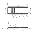
図3は、本発明に係る滅菌用袋の第2の実施形態の一例を示す概略図であり、(a)は平面図であり、(b)は図3(a)のB−B線における断面図である。
第2の実施形態における本発明に係る滅菌用袋は、第1の実施形態において重ね合わせていた非通気性フィルム2の両端部を合掌合わせにしたものである。
(Second Embodiment)
FIG. 3 is a schematic view showing an example of a second embodiment of the sterilization bag according to the present invention, (a) is a plan view, and (b) is taken along line BB in FIG. 3 (a). It is sectional drawing.
In the sterilization bag according to the present invention in the second embodiment, both end portions of the non-breathable film 2 overlapped in the first embodiment are made to be in a palm-to-grind.

図3(a)、及び(b)に示すように、本実施形態においては、非通気性フィルム2が折り曲げ部3で折り曲げられており、合掌合わせ部10で非通気性フィルム2同士が密封されずに合掌合わせの態様で重なっており、周縁ヒートシール部7で両縁がヒートシールされており、折り曲げ部3とは反対側に開口部9が設けられており、開口部9の近くの周縁ヒートシール部7にノッチ8が設けられている。   As shown in FIGS. 3A and 3B, in this embodiment, the non-breathable film 2 is bent at the bent portion 3, and the non-breathable films 2 are hermetically sealed at the jointing portion 10. Without overlapping, and both edges are heat-sealed by the peripheral heat seal part 7, and an opening 9 is provided on the side opposite to the bent part 3. A notch 8 is provided in the heat seal portion 7.

前記滅菌用袋1の内部では、固定ヒートシール部6a、6bで短冊状の滅菌紙5の長辺側の両端がヒートシールにより非通気性フィルム2に固定されている。
合掌合わせ部10における、非通気性フィルム2同士が重なり合う幅は、狭すぎると異物が入り込み易くなり、広すぎると充分な通気量が得られなくなる。それゆえ、この重なり合う幅は、滅菌用袋1の大きさ、滅菌紙5の通気部分の幅、非通気性フィルム2の柔軟性、および滅菌時の減圧速度等を勘案して、決められるが、通常は3mm〜25mm、好ましくは5mm〜15mmの範囲で形成される。
Inside the sterilization bag 1, both ends on the long side of the strip-shaped sterilized paper 5 are fixed to the non-breathable film 2 by heat sealing at the fixed heat seal portions 6a and 6b.
If the width at which the non-breathable films 2 overlap in the palm-joining portion 10 is too narrow, foreign matter can easily enter, and if it is too wide, a sufficient amount of ventilation cannot be obtained. Therefore, the overlapping width is determined in consideration of the size of the sterilization bag 1, the width of the ventilation portion of the sterilized paper 5, the flexibility of the non-breathable film 2, the decompression speed during sterilization, etc. Usually, it is formed in the range of 3 mm to 25 mm, preferably 5 mm to 15 mm.

図4は、前記滅菌用袋に内容物を収納し、密封ヒートシールを施した滅菌用包装体の一例を示す概略図である。
本実施形態における滅菌用包装体30は、図4に示すように、第1の実施形態と同様に、本実施形態の滅菌用袋1に密封ヒートシール部12を設けることにより形成される。
FIG. 4 is a schematic view showing an example of a sterilization package in which the contents are housed in the sterilization bag and hermetically sealed.
As shown in FIG. 4, the sterilization package 30 in the present embodiment is formed by providing a sealed heat seal portion 12 in the sterilization bag 1 of the present embodiment, as in the first embodiment.

上記のようにして形成された滅菌用包装体30は、合掌合わせ部10の未シール部分全体から気体の出入りが可能である。そのため、EOG滅菌時の急激な減圧処理においても充分な通気量が得られ、包装体の膨張は生じ難く、それゆえ破袋し難いという効果を奏する。   The sterilization packaging body 30 formed as described above allows gas to enter and exit from the entire unsealed portion of the palm joint portion 10. Therefore, a sufficient amount of aeration can be obtained even in a rapid decompression process during EOG sterilization, and the package is less likely to swell, and therefore it is difficult to break the bag.

また、滅菌紙5の通気部分は合掌合わせ部10に覆われているため、滅菌紙5に外部からの異物が付着し難いという効果も得られ、衛生上好ましい。
その他、密封ヒートシール等に関して、本実施形態の滅菌用袋、および滅菌用包装体は、第1の実施形態と同様の効果を奏する。
Moreover, since the ventilation | gas_flowing part of the sterilization paper 5 is covered with the palm joint part 10, the effect that the foreign material cannot adhere to the sterilization paper 5 is acquired easily, and it is preferable on hygiene.
In addition, regarding the sealing heat seal and the like, the sterilization bag and the sterilization package of the present embodiment have the same effects as those of the first embodiment.

(第3の実施形態)
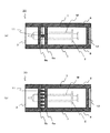
図5は、本発明に係る滅菌用袋の第3の実施形態の一例を示す概略図であり、(a)は、本発明に係る滅菌用袋の第1の実施形態において、重ね合わせ部4の固定ヒートシール部6a、6b間に橋渡しする態様で、破袋防止ヒートシール部11を1箇所設けた例を示す概略図であり、(b)は、同様に、破袋防止ヒートシール部11を複数箇所に設けた例を示す概略図である。また、図6は、図5に示す前記滅菌用袋に内容物を収納し、密封ヒートシールを施した滅菌用包装体の一例を示す概略図であり、図6(a)が図5(a)に、また図6(b)が図5(b)にそれぞれ対応するものである。
(Third embodiment)
FIG. 5 is a schematic view showing an example of the third embodiment of the sterilization bag according to the present invention. FIG. 5A is a schematic view of the overlapping portion 4 in the first embodiment of the sterilization bag according to the present invention. It is the schematic which shows the example which provided the bag breakage prevention heat seal part 11 in the aspect bridge | crosslinked between fixed heat seal part 6a, 6b, and (b) is the bag breakage prevention heat seal part 11 similarly. It is the schematic which shows the example which provided in several places. FIG. 6 is a schematic view showing an example of a sterilization package in which the contents are stored in the sterilization bag shown in FIG. 5 and sealed and heat-sealed, and FIG. And FIG. 6B corresponds to FIG. 5B.

なお、本発明に係る滅菌用袋の第3の実施形態は、本発明に係る滅菌用袋の第2の実施形態において、合掌合わせ部10の1箇所、または複数箇所に、上述同様に破袋防止ヒートシール部11を設けることによっても実施することが出来る。   The third embodiment of the sterilization bag according to the present invention is the same as that described above in the second embodiment of the sterilization bag according to the present invention, in the same manner as described above. It can also be implemented by providing the prevention heat seal part 11.

破袋防止ヒートシール部11の個数や間隔は、滅菌用袋1の大きさ、滅菌用袋1の縦と横の寸法比率、滅菌紙5の通気部分の幅、非通気性フィルム2の柔軟性、滅菌紙5と非通気性フィルム2とのヒートシール強度、破袋防止ヒートシール部11のヒートシール強度、および滅菌時の減圧速度等を勘案して、決められる。   The number and interval of the heat-seal parts 11 for preventing bag breaking are the size of the sterilization bag 1, the vertical and horizontal dimensional ratio of the sterilization bag 1, the width of the ventilation portion of the sterilization paper 5, and the flexibility of the non-breathable film 2 It is determined in consideration of the heat seal strength between the sterilized paper 5 and the non-breathable film 2, the heat seal strength of the bag seal prevention heat seal portion 11, the pressure reduction speed during sterilization, and the like.

破袋防止ヒートシール部11の幅は、狭すぎるとヒートシール条件のコントロールが困難となり、突発的にシール不良が生じる危険性があり、広すぎればその分、滅菌紙5を塞いでしまい無駄であるため、通常は3mm〜15mm、好ましくは5mm〜8mmの範囲で形成される。   If the width of the heat-seal part 11 for preventing bag breaking is too narrow, it becomes difficult to control the heat-seal conditions, and there is a risk that a seal failure may occur suddenly. If it is too wide, the sterilized paper 5 is blocked by that amount, which is useless. Therefore, it is usually formed in a range of 3 mm to 15 mm, preferably 5 mm to 8 mm.

本発明に係る滅菌用袋の第3の実施形態においては、破袋防止ヒートシール部11で滅菌紙5と非通気性フィルム2はヒートシールされており、その分、通気量が減少してしまうが、この破袋防止ヒートシール部11を設けることにより、重ね合わせ部4、または、合掌合わせ部10の内部側に固定されている滅菌紙5が、EOG滅菌時に滅菌用包装体の膨張に伴って破損することを防止できる。
それゆえ、本実施形態に係る滅菌用袋を用いれば、滅菌用包装体は更に破袋し難くなり、EOG滅菌処理にかかる時間を短縮するために急激な減圧を加える場合でも、安心して操作を行えるようになる。
In the third embodiment of the sterilization bag according to the present invention, the sterilized paper 5 and the non-breathable film 2 are heat-sealed by the bag-breaking prevention heat-sealing part 11, and the amount of air flow decreases accordingly. However, by providing the heat-seal part 11 for preventing bag breaking, the sterilized paper 5 fixed on the inner side of the overlapping part 4 or the jointing part 10 is expanded with the expansion of the sterilization package during EOG sterilization. Can be prevented.
Therefore, if the sterilization bag according to the present embodiment is used, the sterilization package is more difficult to break, and even if a sudden decompression is applied to reduce the time required for the EOG sterilization process, the operation can be performed with peace of mind. You can do it.

(第4の実施形態)
図7は、本発明に係る滅菌用袋の第4の実施形態の一例を示す概略図である。ここで、(a)は非通気性フィルム2の両端部を重ね合わせ、または合掌合わせにした形態の概略平面図であり、(b)は図7(a)のC−C線における断面図であって、非通気性フィルム2の両端部を重ね合わせにした形態であり、(c)は図7(a)のC−C線における断面図であって、非通気性フィルム2の両端部を合掌合わせにした形態を示す。
(Fourth embodiment)
FIG. 7 is a schematic view showing an example of a fourth embodiment of a sterilization bag according to the present invention. Here, (a) is a schematic plan view of a form in which both end portions of the non-breathable film 2 are overlapped or joined together, and (b) is a cross-sectional view taken along the line CC in FIG. 7 (a). FIG. 7C is a cross-sectional view taken along the line CC in FIG. 7A, and the both end portions of the non-breathable film 2 are overlapped. Shows the form of the joints.

また、図8は、前記滅菌用袋に内容物を収納し、密封ヒートシールを施した滅菌用包装体の一例を示す概略図である。   FIG. 8 is a schematic view showing an example of a sterilization package in which the contents are stored in the sterilization bag and hermetically sealed.

第4の実施形態における本発明に係る滅菌用袋1は、図7に示すように、第1、または第2の実施形態における滅菌用袋の折り曲げ部3を袋の内側に折り込むことにより形成した片ガゼット袋である。なお、特に図示しないが、本発明に係る第3の実施形態の滅菌用袋1であっても、同様に片ガゼット袋とすることができる。   The sterilization bag 1 according to the present invention in the fourth embodiment is formed by folding the sterilization bag folding portion 3 in the first or second embodiment inside the bag as shown in FIG. It is a single gusset bag. Although not specifically shown, even the sterilization bag 1 according to the third embodiment of the present invention can be similarly formed as a one-gusset bag.

ガゼット折り込み部には、特に図示しないが、ガゼット部両端に斜めにヒートシールを施す、いわゆる船底シールを施しても良く、また、ガゼット底部に縦方向のヒートシール部を設けて底シール部を形成しても良い。   Although not particularly shown, the gusset folding part may be provided with a so-called ship bottom seal that obliquely heat-seals both ends of the gusset part, and a vertical heat seal part is provided at the bottom of the gusset to form a bottom seal part. You may do it.

前記のような片ガゼット袋とすることによって、本発明に係る滅菌用袋1は、より大きな内容物の収納にも対応できることになる。また、滅菌用袋1、および滅菌用包装体30に自立性を付与することも可能である。   By using the one-piece gusset bag as described above, the sterilization bag 1 according to the present invention can also accommodate larger contents. In addition, it is possible to provide the sterilization bag 1 and the sterilization package 30 with self-supporting properties.

ここで、本発明に係る片ガゼット形状を有する滅菌用袋1を用いて、滅菌用包装体30を製造する場合、開口部9にガゼット部が存在しないため、密封ヒートシール部12を形成することに特に困難性は無く、容易に密封性の良い滅菌用包装体30を製造できる。   Here, when manufacturing the sterilization packaging body 30 using the sterilization bag 1 having the one-gazette shape according to the present invention, since the gusset portion does not exist in the opening 9, the sealed heat seal portion 12 is formed. The sterilization package 30 with good sealing properties can be easily manufactured.

しかし、従来の滅菌用包装体32に用いられる滅菌用袋では、開口部にガゼット部が存在してしまうため、滅菌紙5の存在も加わって、密封ヒートシール部12の形成は非常に困難を伴うものとなる。   However, in the sterilization bag used in the conventional sterilization packaging body 32, since the gusset portion exists in the opening, the presence of the sterilized paper 5 is added, and the formation of the sealed heat seal portion 12 is very difficult. It will be accompanied.

(非通気性フィルム)
図9は、本発明に係る滅菌用袋を構成する非通気性フィルムの積層構成の一例を示す断面図であり、(a)は2層構造を、(b)は3層構造を示す。
(Non-breathable film)
FIG. 9 is a cross-sectional view showing an example of a laminated structure of a non-breathable film constituting the sterilization bag according to the present invention, where (a) shows a two-layer structure and (b) shows a three-layer structure.

非通気性フィルム2は、EOG滅菌処理ができる材料により構成されていて、かつ袋体および包装体を形成するためのヒートシール機能も有している必要がある。これらの機能を備えるために、非通気性フィルム2は、図9(a)に示すように、外側から支持基材層40と、ヒートシール性樹脂層41とを順次に積層する積層体を基本構成とする。   The non-breathable film 2 needs to be made of a material that can be EOG sterilized, and also has a heat seal function for forming a bag and a package. In order to provide these functions, the non-breathable film 2 is basically a laminate in which a support base material layer 40 and a heat-sealable resin layer 41 are sequentially laminated from the outside as shown in FIG. 9 (a). The configuration.

支持基材層40は、例えば、ポリアミド樹脂、ポリエステル樹脂、低密度ポリエチレン樹脂、中密度ポリエチレン樹脂、高密度ポリエチレン樹脂、ポリプロピレン樹脂、セロハン等のフィルムないしシ−トを単体の支持基材でもよく、あるいは二種以上の支持基材を組み合わせてなる複合支持基材等であってもよい。
支持基材層40の厚さは5〜100μm位であり、好ましくは12〜50μm位が望ましい。
The support base layer 40 may be, for example, a single support base made of a film or sheet such as polyamide resin, polyester resin, low density polyethylene resin, medium density polyethylene resin, high density polyethylene resin, polypropylene resin, cellophane, Or the composite support base material etc. which combine 2 or more types of support base materials may be sufficient.
The thickness of the support base material layer 40 is about 5 to 100 μm, preferably about 12 to 50 μm.

なお、本発明においては、例えば、文字、図形、記号、絵柄、模様等の所望の印刷絵柄をオフセット印刷あるいはグラビア印刷、フレキソ印刷、凸版印刷、シルクスクリーン印刷、その他の通常の印刷法で、必要に応じて支持基材層40の片面に印刷されていてもよい。   In the present invention, for example, a desired print pattern such as a character, a figure, a symbol, a pattern, and a pattern is necessary for offset printing, gravure printing, flexographic printing, letterpress printing, silk screen printing, and other ordinary printing methods. Depending on, it may be printed on one side of the support base material layer 40.

ヒートシール性樹脂層41は、EOG滅菌処理できる材料からなり、滅菌用袋1の周縁ヒートシール部7、及び滅菌用包装体30の密封ヒートシール部12を確実にヒートシールすることができ、滅菌紙5とヒートシール可能なものであればよい。   The heat-sealable resin layer 41 is made of a material that can be subjected to EOG sterilization, and can reliably heat-seal the peripheral heat seal part 7 of the sterilization bag 1 and the sealed heat seal part 12 of the sterilization package 30. Any material that can be heat-sealed with the paper 5 may be used.

ヒートシール性樹脂層41に用いるフィルム材としては、ヒートシール性樹脂層41の面同士のヒートシールが弱シールとなる、いわゆる面々イージピール性シーラントフィルムや、ヒートシール性樹脂層41の面同士のヒートシールが強シールとなる、ポリエチレンフィルム、ポリプロピレンフィルム、アイオノマーフィルム、エチレン−酢酸ビニル共重合体フィルム等を使用することができる。
ヒートシール性樹脂層41の厚さは、10〜80μm位が好ましい。
As a film material used for the heat-sealable resin layer 41, a so-called easy peel sealant film in which the heat-seal between the surfaces of the heat-sealable resin layer 41 becomes a weak seal, or heat between the surfaces of the heat-sealable resin layer 41 is used. A polyethylene film, a polypropylene film, an ionomer film, an ethylene-vinyl acetate copolymer film, or the like that makes a strong seal can be used.
The thickness of the heat-sealable resin layer 41 is preferably about 10 to 80 μm.

ここで、本発明に係る滅菌用袋の第2の実施形態に示す非通気性フィルム2の両端を合掌合わせした態様の場合には、合掌合わせ部10をヒートシールすれば、合掌合わせされた面のヒートシール性樹脂層41同士がヒートシールされるため、第3の実施形態における破袋防止ヒートシール部11を切れ目無く形成することが可能である。   Here, in the case of a mode in which both ends of the non-breathable film 2 shown in the second embodiment of the sterilization bag according to the present invention are joined together, if the joining unit 10 is heat-sealed, the joined surface is joined. Since the heat-sealable resin layers 41 are heat-sealed, it is possible to form the bag-breaking-preventing heat-seal portion 11 in the third embodiment without breaks.

また、本発明に係る非通気性フィルム2は、図9(b)に示すように、外側からヒートシール性樹脂層41と、支持基材層40と、ヒートシール性樹脂層41とを順次に積層する積層体としても良い。   In addition, as shown in FIG. 9B, the non-breathable film 2 according to the present invention sequentially includes a heat sealable resin layer 41, a support base material layer 40, and a heat sealable resin layer 41 from the outside. It is good also as a laminated body to laminate.

前記3層構造の非通気性フィルム2を用いて、本発明に係る滅菌用袋の第1の実施形態に示す重ね合わせ部4をヒートシールすれば、重ね合わせ部4の非通気性フィルム2の内側と外側の各ヒートシール性樹脂層41同士がヒートシールされるため、第3の実施形態における破袋防止ヒートシール部11を切れ目無く形成することが可能である。   If the overlapping portion 4 shown in the first embodiment of the sterilization bag according to the present invention is heat-sealed using the three-layer structure of the non-breathable film 2, Since the inner and outer heat-sealable resin layers 41 are heat-sealed, the bag-breaking prevention heat-seal portion 11 in the third embodiment can be formed without a break.

なお、本発明に係る非通気性フィルム2は、上記の層構成に限定されず、図示しないが、例えば、支持基材層40の片面に印刷層を形成してもよく、また、支持基材層40と、ヒートシール性樹脂層41との間に必要に応じて接着層や、耐ピンホール層等の中間層を設けることができる。   In addition, the air-impermeable film 2 according to the present invention is not limited to the above-described layer configuration, and although not illustrated, for example, a printed layer may be formed on one side of the support base material layer 40. An intermediate layer such as an adhesive layer or a pinhole-resistant layer can be provided between the layer 40 and the heat-sealable resin layer 41 as necessary.

また、本発明に係る非通気性フィルム2の各層を形成する樹脂には、本発明の目的の達成を阻害しない範囲で、滑剤、酸化防止剤、帯電防止剤等の添加剤を随時添加することができる。   In addition, additives such as lubricants, antioxidants, and antistatic agents may be added to the resin that forms each layer of the non-breathable film 2 according to the present invention as long as the object of the present invention is not impaired. Can do.

本発明に係る非通気性フィルム2の支持基材層40とヒートシール性樹脂層41を積層する方法としては、熱接着性樹脂を用いてTダイ押し出しラミネーション法によってラミネートしても良いし、また、2液硬化型のウレタン系接着剤を用いてドライラミネート法によってラミネートしても良いし、また、共押し出しによる複層フィルムを用いても良い。Tダイ押し出しラミネーション法の場合は必要に応じてアンカーコート剤を用いることができる。   As a method of laminating the support base material layer 40 and the heat-sealable resin layer 41 of the non-breathable film 2 according to the present invention, it may be laminated by a T-die extrusion lamination method using a heat-adhesive resin, It may be laminated by a dry laminating method using a two-component curable urethane adhesive, or a multilayer film by coextrusion may be used. In the case of the T-die extrusion lamination method, an anchor coating agent can be used as necessary.

(滅菌紙)
本発明において、菌を通さない通気性材料よりなる滅菌紙5は、例えば、アンコート紙、不織布、和紙等からなるものを使用することができる。
そして、前記の不織布としては、例えば、タイベック(デュポンジャパンリミテッド社製)、ルクサー(旭化成工業株社製)等を使用することができる。
(Sterilized paper)
In the present invention, as the sterilized paper 5 made of a breathable material that does not allow passage of bacteria, for example, those made of uncoated paper, non-woven fabric, Japanese paper or the like can be used.
And as said nonwoven fabric, Tyvek (made by DuPont Japan Limited), Luxer (made by Asahi Kasei Kogyo Co., Ltd.), etc. can be used, for example.

また、不織布、和紙等の片面に穴開きポリエチレン、または日本石油(株)製日石ワリフ、倉敷紡績(株)製クレネット、新日本ソフ(株)製ソフネット、及びソフクロス等のポリエチレン、ポリプロピレン等からなるネット状強化材を積層したものを使用することができる。   In addition, polyethylene, polypropylene such as non-woven fabric, Japanese paper, etc. with holes perforated, Nippon Oil Co., Ltd. Nisseki Warif, Kurashiki Boseki Co., Ltd., Shin Nippon Sof Co., Ltd., Sofcross, etc. What laminated | stacked the net-shaped reinforcement which consists of etc. can be used.

上記の滅菌紙5は、厚さや材質によって通気速度を変えることができるので、滅菌時の温度条件(例えば50〜70℃)や減圧速度の大小を考慮して適宜選定する。   The above-mentioned sterilized paper 5 can change the aeration rate depending on the thickness and material, and therefore is appropriately selected in consideration of the temperature conditions during sterilization (for example, 50 to 70 ° C.) and the pressure reduction rate.

(第1および第2の実施形態に係る滅菌用袋の製造方法)
本発明に係る滅菌用袋1の製造方法は、特に限定されるものではないが、例えば、一般的なテープ挿入機構付ピロー袋製袋機を用いて製造することができる。
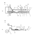
図10は前記製袋機の一例を示す概略図であり、(a)は平面図であり、(b)は側面図である。
(Manufacturing method of sterilization bag according to first and second embodiments)
Although the manufacturing method of the sterilization bag 1 which concerns on this invention is not specifically limited, For example, it can manufacture using a general pillow bag making machine with a tape insertion mechanism.
FIG. 10 is a schematic view showing an example of the bag making machine, where (a) is a plan view and (b) is a side view.

まず、非通気性フィルム2、および滅菌紙5を、図10(a)、及び(b)に示すように、巻取り状態で製袋機20に装填し、各々帯状に引き出す。なお、帯状の滅菌紙5の幅方向の寸法は、前記帯状の非通気性フィルムの幅方向の寸法よりも小さいものである。   First, as shown in FIGS. 10A and 10B, the non-breathable film 2 and the sterilized paper 5 are loaded into the bag making machine 20 in a wound state, and each is drawn out in a band shape. In addition, the dimension of the width direction of the strip | belt-shaped sterilization paper 5 is a thing smaller than the dimension of the width direction of the said strip | belt-shaped non-breathable film.

ここで、滅菌紙5、および製袋プレート21は、引き出される帯状の非通気性フィルム2の幅方向の中央から端寄りにずらして配置される。製袋機20によって、ずらし可能寸法は異なるが、通常は簡単な改造で滅菌紙5、および製袋プレート21の取り付け治具の位置をずらすことが可能である。   Here, the sterilized paper 5 and the bag making plate 21 are arranged so as to be shifted from the center in the width direction of the strip-shaped non-breathable film 2 to be pulled out toward the end. Although the shiftable dimensions differ depending on the bag making machine 20, it is usually possible to shift the positions of the sterilized paper 5 and the mounting jig for the bag making plate 21 with a simple modification.

続いて、引き出した非通気性フィルム2をヒートシール性樹脂層41が内面側になるように、製袋プレート21に沿って2箇所で折り曲げて、両端を重ね合わせ、または合掌合わせして略筒状に形成すると共に、帯状の滅菌紙5を製袋プレート21と、重ね合わせ部4、または合掌合わせ部10との間に通すように配置して、滅菌紙5を内側から非通気性フィルム2の内面にあてがい、縦ヒートシールバー22で固定ヒートシール部6a、6bのヒートシールを連続的に施す。   Subsequently, the drawn air-impermeable film 2 is bent at two locations along the bag-making plate 21 so that the heat-sealable resin layer 41 is on the inner surface side, and both ends are overlapped or joined together to form a substantially cylinder. The band-shaped sterilized paper 5 is disposed so as to pass between the bag-making plate 21 and the overlapping portion 4 or the palm-joining portion 10, and the sterilized paper 5 is inserted from the inside to the air-impermeable film 2. The fixed heat seal portions 6a and 6b are continuously heat sealed by the vertical heat seal bar 22.

その後、横ヒートシールバー23で略筒状の非通気性フィルム2の幅方向に平行にヒートシールを一定間隔で施して、周縁ヒートシール部7を設け、周縁ヒートシール部7に、ノッチ8の孔を、抜き治具24で開ける。   Thereafter, heat sealing is performed at regular intervals in parallel to the width direction of the substantially cylindrical non-breathable film 2 with the horizontal heat seal bar 23 to provide the peripheral heat seal portion 7, and the peripheral heat seal portion 7 has notches 8. A hole is opened with a punching jig 24.

図11は、前記製造方法における、抜き治具24でノッチ8の孔を設けた後の非通気性フィルム2の形態を示すものである。ここで、図11の上下方向が帯状に引き出された非通気性フィルム2の長手方向である。   FIG. 11 shows the form of the non-breathable film 2 after the hole of the notch 8 is provided by the punching jig 24 in the manufacturing method. Here, the vertical direction of FIG. 11 is the longitudinal direction of the non-breathable film 2 drawn out in a strip shape.

その後、レザー刃25で、折り曲げ部の片方を切断部27で切り落として、開口部9を形成し、裁断刃26により、非通気性フィルム2を、周縁ヒートシール部7の中央で幅方向に裁断して、滅菌用袋1を得る。   Thereafter, one side of the bent portion is cut off by the cutting portion 27 with the leather blade 25 to form the opening 9, and the air-impermeable film 2 is cut in the width direction at the center of the peripheral heat seal portion 7 by the cutting blade 26. Thus, the sterilization bag 1 is obtained.

前記製造方法により得られた、本発明に係る滅菌用袋1は、重ね合わせ部4、または合掌合わせ部10の未シール部分全体から気体の出入りが可能である。そのため、前記滅菌用袋から形成した滅菌用包装体は、EOG滅菌時の急激な減圧処理においても充分な通気量を得ることができ、包装体の膨張は生じ難く、それゆえ破袋し難いという効果を奏する。   The sterilization bag 1 according to the present invention obtained by the manufacturing method can allow gas to enter and exit from the entire unsealed portion of the overlapping portion 4 or the jointing portion 10. Therefore, the sterilization package formed from the sterilization bag can obtain a sufficient amount of air flow even in a rapid decompression process during EOG sterilization, and the package does not easily expand, and is therefore difficult to break. There is an effect.

また、本発明に係る滅菌用袋の製造方法によれば、帯状の非通気性フィルム2の引き出し方向に対し、滅菌用袋1を横長で製袋できるため、帯状に連続して挟み込まれる滅菌紙5の袋毎の長手方向の寸法も小さて済むことになり、従来の滅菌用包装体32に用いられる縦長の滅菌用袋に比べ、袋毎の滅菌紙5の使用量を、より減らすことができる。   Further, according to the method for manufacturing a sterilization bag according to the present invention, since the sterilization bag 1 can be made horizontally long with respect to the drawing direction of the band-shaped non-breathable film 2, the sterilized paper sandwiched continuously in the band shape. The size in the longitudinal direction for each of the five bags is also small, and the amount of sterilized paper 5 used for each bag can be further reduced as compared with the vertically long sterilization bag used for the sterilization packaging body 32. it can.

さらに、上記のように、滅菌用袋1を横長で製袋できるため、従来の滅菌用包装体32に用いられる縦長の滅菌用袋を製造する場合に比べ、時間あたりの製袋数量が増えるという、製袋能率の向上効果も奏する。   Further, as described above, since the sterilization bag 1 can be made in a horizontally long bag, the amount of bag making per hour is increased as compared with the case of manufacturing a vertically long sterilization bag used for the conventional sterilization package 32. Also, the effect of improving the bag-making efficiency is achieved.

この理由は、通常の製袋機20で、同一のフィルム構成で、特定の大きさの長方形の袋を、縦長で製袋する場合と、横長で製袋する場合とでは、ヒートシール時間は同一に設定するが、1ショット毎のフィルムの送り長さは縦長のほうが長いため、結果的に、フィルムの送りに要する時間は横長の方が縦長よりも短くできるからである。   This is because the normal bag making machine 20 has the same film configuration, and a rectangular bag of a specific size is produced in a vertically long form and in a horizontally long form, the heat sealing time is the same. However, since the film feed length per shot is longer in the longitudinal direction, as a result, the time required for feeding the film can be shorter in the lateral direction than in the longitudinal direction.

なお、前記製造方法においては、前記製袋機20の下流に包装機を結合させた製袋包装機を用いることも可能である。   In the manufacturing method, a bag making and packaging machine in which a packaging machine is coupled downstream of the bag making machine 20 can be used.

(第3の実施形態に係る滅菌用袋の製造方法)
本発明に係る第3の実施形態の滅菌用袋は、例えば、前記製造方法に加えて、破袋防止ヒートシール部11を形成する手段を設けることにより製造できる。
破袋防止ヒートシール部11を形成する通常の手段としては、縦ヒートシールバー22を加工して、固定部6a、6b形成用の縦2本のヒートシール部の間に、横方向のヒートシール部を付け加える方法が最も一般的である。
(Manufacturing method of sterilization bag according to the third embodiment)
The sterilization bag according to the third embodiment of the present invention can be manufactured, for example, by providing means for forming the bag breaking prevention heat seal portion 11 in addition to the manufacturing method.
As a normal means for forming the bag-breaking prevention heat seal portion 11, the vertical heat seal bar 22 is processed, and the heat seal in the horizontal direction is interposed between the two vertical heat seal portions for forming the fixing portions 6a and 6b. The most common method is to add parts.

上述の方法のように、縦ヒートシールバー22でヒートシールする場合には、ヒートシール部の下に製袋プレート21があるため、滅菌用袋1の内面同士がヒートシールされる心配はない。   When heat sealing is performed with the vertical heat seal bar 22 as in the above-described method, there is no concern that the inner surfaces of the sterilization bags 1 are heat sealed because the bag-making plate 21 is located under the heat seal portion.

一方、横ヒートシールバー23や、ポイントシールで破袋防止ヒートシールを実施する場合には、当該ヒートシール時に滅菌用袋1の内面同士がヒートシールされないようにする必要があり、困難を伴うことになる。   On the other hand, in the case of carrying out the bag breaking prevention heat sealing with the horizontal heat seal bar 23 or the point seal, it is necessary to prevent the inner surfaces of the sterilization bags 1 from being heat sealed at the time of the heat sealing, which is difficult. become.

(第4の実施形態に係る滅菌用袋の製造方法)
本発明に係る第4の実施形態の滅菌用袋は、例えば、前記製造方法にガゼット部を形成する手段を設けることにより製造できる。例えば、前記製袋機20において非通気性フィルム2の両端を重ね合わせ、または合掌合わせした後、縦ヒートシール工程の手前で円盤状の回転するプレートを折り込み部にあてがうことにより、ガゼット部を形成することができる。
(Manufacturing method of the sterilization bag according to the fourth embodiment)
The sterilization bag according to the fourth embodiment of the present invention can be manufactured, for example, by providing means for forming a gusset portion in the manufacturing method. For example, after the two ends of the non-breathable film 2 are overlapped or joined with each other in the bag making machine 20, a gusset portion is formed by applying a disk-shaped rotating plate to the folding portion before the vertical heat sealing step. can do.

次に実施例を挙げて、本発明を更に具体的に説明する。
(実施例1)
支持基材層40として、厚さ20μm、幅760mmの2軸延伸ポリプロピレンフィルム(品名「FOR」フタムラ化学株式会社製)を用い、ヒートシール性樹脂層41として、厚さ30μm、幅760mmのポリエチレンフィルム(品名「L4102」東洋紡績株式会社製)を準備し、ウレタン樹脂系の2液混合型ラミネート接着剤(塗布量は3g/m2)を介して積層した後、両端を切り落としつつ小幅に断裁し、幅370mmで、層構成が2軸延伸ポリプロピレンフィルム(20μm)/2液混合型ラミネート接着層/ポリエチレンフィルム(30μm)となる非通気性フィルム2を製造した。
Next, the present invention will be described more specifically with reference to examples.
Example 1
A biaxially stretched polypropylene film (product name “FOR” manufactured by Futamura Chemical Co., Ltd.) having a thickness of 20 μm and a width of 760 mm is used as the supporting base material layer 40, and a polyethylene film having a thickness of 30 μm and a width of 760 mm is used as the heat-sealable resin layer 41. (Product name "L4102" manufactured by Toyobo Co., Ltd.) was prepared and laminated via a urethane resin-based two-component mixed laminating adhesive (amount applied: 3 g / m 2 ), and then cut into small widths while cutting off both ends. A non-breathable film 2 having a width of 370 mm and a layer configuration of biaxially stretched polypropylene film (20 μm) / 2-component mixed laminate adhesive layer / polyethylene film (30 μm) was produced.

また、滅菌紙5として、坪量73g/m2、幅25mmのタイベック1073B(デュポン社製)を準備した。 As sterilized paper 5, Tyvek 1073B (manufactured by DuPont) having a basis weight of 73 g / m 2 and a width of 25 mm was prepared.

そして、製袋機20として、テープ供給装置付きピロー製袋機を用いて、上記で得られた非通気性フィルム2を製袋幅180mm用の製袋プレート21に沿って折り曲げ、巻き付けて、製袋機20の上流側から見て右側の折り曲げ部から50mmの位置が重ね合わせ部4の中心となるように非通気性フィルム2両端を10mm重ね合わせて略筒状に成形すると共に、滅菌紙5を、製袋プレート21と重ね合わせ部4との間に通して、重ね合わせ部4の中心と滅菌紙5の中心を合わせるようにして、非通気性フィルム2の内面側にあてがい、図12(a)に示すように、固定部間の内寸法(L1)が17mm、幅(L2)が5mmとなるように固定ヒートシール部6a、6bを、2本線の縦ヒートシールバー22で、連続的にヒートシール施した。   Then, using the pillow bag making machine with a tape supply device as the bag making machine 20, the non-breathable film 2 obtained above is folded and wound along the bag making plate 21 for a bag making width of 180 mm to produce the bag making machine 20. The both sides of the non-breathable film 2 are overlapped with each other by 10 mm so that the position of 50 mm from the bent portion on the right side when viewed from the upstream side of the bag machine 20 is the center of the overlapping portion 4 and formed into a substantially cylindrical shape. Is passed between the bag-making plate 21 and the overlapping portion 4 so that the center of the overlapping portion 4 and the center of the sterilized paper 5 are aligned with each other on the inner surface side of the non-breathable film 2. As shown in a), the fixed heat seal portions 6a and 6b are continuously connected by a two-line vertical heat seal bar 22 so that the inner dimension (L1) between the fixed portions is 17 mm and the width (L2) is 5 mm. Heat-sealed .

その後、ヒートシール幅20mmの横ヒートシールバー23により40mm間隔で周縁ヒートシール部7を設け、製袋機20の上流側から見て左側の折り曲げ端から35mmの位置にノッチ8の孔を抜き治具24で開けた。   Thereafter, a peripheral heat seal portion 7 is provided at intervals of 40 mm by a horizontal heat seal bar 23 having a heat seal width of 20 mm, and a hole in the notch 8 is removed at a position 35 mm from the left bent end when viewed from the upstream side of the bag making machine 20. Opened with tool 24.

その後、レザー刃25で製袋機20の上流側から見て左側の折り曲げ端から10mmの位置で折り曲げ端の片方を切り落として開口部9を形成し、周縁ヒートシール部7のほぼ中央で断裁して縦50mm、横170mm、周縁ヒートシール部7の幅10mmの滅菌用袋1を得た。   Thereafter, an opening 9 is formed by cutting off one of the bent ends at a position 10 mm from the left bent end when viewed from the upstream side of the bag making machine 20 with the leather blade 25, and cutting is performed at substantially the center of the peripheral heat seal portion 7. Thus, a sterilization bag 1 having a length of 50 mm, a width of 170 mm, and a peripheral heat seal portion 7 of 10 mm in width was obtained.

(実施例2)
非通気性フィルム2、滅菌紙5、および製袋機20は、実施例1と同じものを用いた。
非通気性フィルム2を製袋幅175mm用の製袋プレート21に沿って折り曲げ、巻き付けて、製袋機20の上流側から見て右側の折り曲げ部から45mmの位置において、非通気性フィルム2のポリエチレンフィルム面同士を、製袋機20の上流側から見て非通気性フィルム2の左端から11mm、右端から9mmで合掌合わせし、合掌合わせ部10を右側に倒して略筒状に成形すると共に、滅菌紙5を、製袋プレート21と合掌合わせ部10との間に通して、滅菌紙5の中心が製袋機20の上流側から見て右側から50mmの位置となるようにして非通気性フィルム2の内面側にあてがい、図12(a)に示すように、固定部間の内寸法(L1)が17mm、幅(L2)が5mmとなるように固定ヒートシール部6a、6bを、2本線の縦ヒートシールバー22で、連続的にヒートシール施した後、ヒートシール幅20mmの横ヒートシールバー23により40mm間隔で周縁ヒートシール部9を設け、製袋機20の上流側から見て左側の折り曲げ端から30mmの位置にノッチ8の孔を抜き治具24で開けた。
(Example 2)
The non-breathable film 2, the sterilized paper 5, and the bag making machine 20 were the same as those in Example 1.
The non-breathable film 2 is folded and wrapped along a bag making plate 21 for a bag making width of 175 mm, and the non-breathable film 2 is placed at a position 45 mm from the right bent portion when viewed from the upstream side of the bag making machine 20. The polyethylene film surfaces are aligned with each other at 11 mm from the left end and 9 mm from the right end of the non-breathable film 2 when viewed from the upstream side of the bag making machine 20, and the alignment unit 10 is tilted to the right side to form a substantially cylindrical shape. The sterilized paper 5 is passed between the bag making plate 21 and the jointing unit 10 so that the center of the sterilized paper 5 is 50 mm from the right side when viewed from the upstream side of the bag making machine 20 and is not ventilated. As shown in FIG. 12 (a), the fixed heat seal portions 6a and 6b are applied to the inner surface side of the adhesive film 2 so that the inner dimension (L1) between the fixed portions is 17 mm and the width (L2) is 5 mm. Two lines After heat-sealing continuously with the heat-seal bar 22, the peripheral heat-seal part 9 is provided at intervals of 40 mm by the horizontal heat-seal bar 23 having a heat-seal width of 20 mm, and the left side is bent when viewed from the upstream side of the bag making machine 20. A hole of the notch 8 was punched with a jig 24 at a position 30 mm from the end.

その後、レザー刃25で製袋機20の上流側から見て左側の折り曲げ端から5mmの位置で折り曲げ端の片方を切り落として開口部9を形成し、周縁ヒートシール部7のほぼ中央で断裁して縦50mm、横170mm、周縁ヒートシール部7の幅10mmの滅菌用袋1を得た。   Thereafter, an opening 9 is formed by cutting off one end of the bent end at a position 5 mm from the left bent end as viewed from the upstream side of the bag making machine 20 with the leather blade 25, and cutting is performed at substantially the center of the peripheral heat seal portion 7. Thus, a sterilization bag 1 having a length of 50 mm, a width of 170 mm, and a peripheral heat seal portion 7 of 10 mm in width was obtained.

(実施例3)
図12(b)に示すように、固定ヒートシール部6a、6b形成用の縦2本ヒートシール部の間に横方向のヒートシール部を付け加えた縦ヒートシールバー22を用いて、固定ヒートシール部6a、6bの間を橋渡しする態様で、幅(L3)が5mmの破袋防止ヒートシール部11を形成した以外は実施例2と同一条件で、破袋防止ヒートシール部11を1箇所有する、縦50mm、横170mm、周縁ヒートシール部7の幅10mmの滅菌用袋1を製造した。
(Example 3)
As shown in FIG. 12 (b), a fixed heat seal is formed by using a vertical heat seal bar 22 in which a horizontal heat seal portion is added between two vertical heat seal portions for forming the fixed heat seal portions 6a and 6b. In the form of bridging between the parts 6a and 6b, the bag-breaking prevention heat seal part 11 having one place is provided under the same conditions as in Example 2 except that the bag-breaking prevention heat seal part 11 having a width (L3) of 5 mm is formed. A sterilization bag 1 having a length of 50 mm, a width of 170 mm, and a peripheral heat seal part 7 having a width of 10 mm was produced.

(実施例4)
支持基材層40として、厚さ25μm、幅760mmの2軸延伸ポリエチレンテレフタレートフィルム(品名「E5202」東洋紡績株式会社製)を用い、ヒートシール性樹脂層41として、厚さ20μmの溶融ポリエチレン樹脂を、アンカーコート剤を介して前記2軸延伸ポリエチレンテレフタレートフィルムの両面に押し出しラミネートにより積層した後、両端を切り落としつつ小幅に断裁し、幅370mmで、層構成がポリエチレンフィルム(20μm)/アンカーコート剤/2軸延伸ポリエチレンテレフタレートフィルム(25μm)/アンカーコート剤/ポリエチレンフィルム(20μm)となる非通気性フィルム2を製造した。
Example 4
A biaxially stretched polyethylene terephthalate film (product name “E5202” manufactured by Toyobo Co., Ltd.) having a thickness of 25 μm and a width of 760 mm is used as the supporting base material layer 40, and a molten polyethylene resin having a thickness of 20 μm is used as the heat-sealable resin layer 41. Then, both layers of the biaxially stretched polyethylene terephthalate film were laminated by extrusion lamination via an anchor coating agent, and then cut into small widths while cutting off both ends. The width was 370 mm and the layer structure was a polyethylene film (20 μm) / anchor coating agent / A non-breathable film 2 to be a biaxially stretched polyethylene terephthalate film (25 μm) / anchor coating agent / polyethylene film (20 μm) was produced.

そして、実施例3と同じ縦ヒートシールバー22を用いた以外は実施例1と同じ条件で製袋することにより、重ね合わせ部4に破袋防止ヒートシール部11を1箇所有する、縦50mm、横170mm、周縁ヒートシール部7の幅10mmの滅菌用袋1を製造した。   And by using the same vertical heat seal bar 22 as in Example 3 and making bags under the same conditions as in Example 1, the overlapping part 4 has one bag-breaking prevention heat seal part 11 in a 50 mm length, A sterilization bag 1 having a width of 170 mm and a peripheral heat seal portion 7 having a width of 10 mm was produced.

(実施例5)
実施例4と同じ非通気性フィルム2と、実施例3と同じ縦ヒートシールバー22を用いた以外は、実施例2と同様に製袋することにより、合掌合わせ部10に破袋防止ヒートシール部11を1箇所有する、縦50mm、横170mm、周縁ヒートシール部7の幅10mmの滅菌用袋1を製造した。
(Example 5)
A bag-break-preventing heat seal is formed in the palm-joining portion 10 by making a bag in the same manner as in Example 2 except that the same non-breathable film 2 as in Example 4 and the same vertical heat seal bar 22 as in Example 3 are used. A sterilization bag 1 having one part 11 and having a length of 50 mm, a width of 170 mm, and a peripheral heat seal part 7 having a width of 10 mm was produced.

(実施例6)
実施例4と同じ積層構成の非通気性フィルム2であって、幅を420mmとした非通気性フィルム2と、実施例3と同じ縦ヒートシールバー22を用い、通常の片ガゼット折り込み工程の他は、実施例2と同様に製袋することにより、合掌合わせ部10に破袋防止ヒートシール部11を1箇所有する、縦50mm、横170mm、ガゼット部の幅25mm、周縁ヒートシール部9の幅10mmの片ガゼット形状の滅菌用袋1を製造した。
(Example 6)
A non-breathable film 2 having the same laminated structure as in Example 4 and using the non-breathable film 2 having a width of 420 mm and the same vertical heat seal bar 22 as in Example 3, in addition to a normal one-piece gusset folding process Is made in the same manner as in Example 2 to have one bag seal preventing heat seal portion 11 in the palm-joining portion 10, 50 mm long, 170 mm wide, 25 mm width of the gusset portion, and the width of the peripheral heat seal portion 9. A sterilization bag 1 having a 10-mm gusset shape was produced.

(実施例7)
上記実施例1〜6で得られた滅菌用袋1に、内容物Mとして10mlのポリプロピレン製空シリンジを収納し、開口部9から5mmの位置で、インパルスシーラー(富士インパルス株式会社製FA−450−5W)を用いて、加熱1.0秒、冷却1.3秒で、シール幅5mmの密封ヒートシール部12を設けて滅菌用包装体30を製造した。
(Example 7)
In the sterilization bag 1 obtained in the above Examples 1 to 6, 10 ml of an empty polypropylene syringe is stored as the contents M, and an impulse sealer (FA-450 manufactured by Fuji Impulse Co., Ltd.) is placed at a position 5 mm from the opening 9. -5W), a sealed heat seal portion 12 having a seal width of 5 mm was provided for 1.0 second with heating and 1.3 seconds with cooling to produce a sterilization package 30.

(実施例8)
上記の製造方法で得られた本発明に係る滅菌用包装体30をEOGインジケータ−(ATI社製)に入れてから、真空圧−85kPa、滅菌温度60℃、滅菌時間2時間、湿度70%、滅菌圧力−35kPa、洗浄数6回の条件下において滅菌処理を施したところ、前記滅菌用包装体30は、滅菌中に破袋することは無かった。
(Example 8)
After putting the sterilization packaging body 30 according to the present invention obtained by the above production method into an EOG indicator (manufactured by ATI), vacuum pressure -85 kPa, sterilization temperature 60 ° C., sterilization time 2 hours, humidity 70%, When sterilization was performed under the conditions of sterilization pressure -35 kPa and 6 washings, the sterilization package 30 was not broken during sterilization.

本発明に係る滅菌用袋の第1の実施形態の一例を示す概略図であり、(a)は平面図であり、(b)は図1(a)のA−A線における断面図である。It is the schematic which shows an example of 1st Embodiment of the bag for sterilization concerning this invention, (a) is a top view, (b) is sectional drawing in the AA of FIG. 1 (a). . 本発明に係る滅菌用包装体の第1の実施形態の一例を示す概略図である。It is the schematic which shows an example of 1st Embodiment of the packaging body for sterilization concerning this invention. 本発明に係る滅菌用袋の第2の実施形態の一例を示す概略図であり、(a)は平面図であり、(b)は図3(a)のB−B線における断面図である。It is the schematic which shows an example of 2nd Embodiment of the sterilization bag which concerns on this invention, (a) is a top view, (b) is sectional drawing in the BB line of Fig.3 (a). . 本発明に係る滅菌用包装体の第2の実施形態の一例を示す概略図である。It is the schematic which shows an example of 2nd Embodiment of the packaging body for sterilization concerning this invention. 本発明に係る滅菌用袋の第3の実施形態の一例を示す概略図であり、(a)は破袋防止ヒートシール部を1箇所設けた例の概略図であり、(b)は破袋防止ヒートシール部を複数箇所設けた例の概略図である。It is the schematic which shows an example of 3rd Embodiment of the bag for sterilization which concerns on this invention, (a) is the schematic of the example which provided the bag sealing prevention heat seal part in one place, (b) is bag breaking It is the schematic of the example which provided the prevention heat seal part in multiple places. 本発明に係る滅菌用包装体の第3の実施形態の一例を示す概略図であり、(a)は破袋防止ヒートシール部を1箇所設けた例の概略図であり、(b)は破袋防止ヒートシール部を複数箇所設けた例の概略図である。It is the schematic which shows an example of 3rd Embodiment of the packaging body for sterilization which concerns on this invention, (a) is the schematic of the example which provided one bag-breaking prevention heat seal part, (b) is broken It is the schematic of the example which provided the bag prevention heat seal part in multiple places. 本発明に係る滅菌用袋の第4の実施形態の例を示す概略図であり、(a)は平面図であり、(b)は該実施形態の一例を示す断面図であり、(c)は他の例を示す断面図である。It is the schematic which shows the example of 4th Embodiment of the bag for sterilization concerning this invention, (a) is a top view, (b) is sectional drawing which shows an example of this embodiment, (c) FIG. 6 is a cross-sectional view showing another example. 本発明に係る滅菌用包装体の第4の実施形態の一例を示す概略図である。It is the schematic which shows an example of 4th Embodiment of the sterilization packaging body which concerns on this invention. 本発明に係る滅菌用袋を構成する非通気性フィルムの一例を示す断面図であり、(a)は2層構造の断面図であり、(b)は3層構造の断面図である。It is sectional drawing which shows an example of the non-breathable film which comprises the bag for sterilization concerning this invention, (a) is sectional drawing of 2 layer structure, (b) is sectional drawing of 3 layer structure. 本発明に係る滅菌用袋を製造する製袋機の一例を示す概略図であり、(a)は平面図であり、(b)は側面図である。It is the schematic which shows an example of the bag making machine which manufactures the bag for sterilization concerning this invention, (a) is a top view, (b) is a side view. 本発明に係る滅菌用袋を構成する非通気性フィルムを、図10に示した製袋機により加工した例を示す図である。It is a figure which shows the example which processed the non-breathable film which comprises the bag for sterilization based on this invention with the bag making machine shown in FIG. 本発明に係る滅菌用袋の固定ヒートシール部の各寸法を示す図である。It is a figure which shows each dimension of the fixed heat seal part of the sterilization bag which concerns on this invention. 従来の滅菌用袋からなる滅菌用包装体の概略図であり、(a)は平面図、(b)は図13(a)のD−D線における断面図である。It is the schematic of the sterilization packaging body which consists of the conventional sterilization bag, (a) is a top view, (b) is sectional drawing in the DD line | wire of Fig.13 (a).

符号の説明Explanation of symbols

1 滅菌用袋
2 非通気性フィルム
3 折り曲げ部
4 重ね合わせ部
5 滅菌紙
6a 中心寄り固定ヒートシール部
6b 端寄り固定ヒートシール部
7 周縁ヒートシール部
8 ノッチ
9 開口部
10 合掌合わせ部
11 破袋防止ヒートシール部
12 密封ヒートシール部
20 製袋機
21 製袋プレート
22 縦ヒートシールバー
23 横ヒートシールバー
24 抜き治具
25 レザー刃
26 裁断刃
27 切断部
28 裁断部
30 滅菌用包装体
40 支持基材層
41 ヒートシール性樹脂層
51 中心線
52 円
M 内容物

DESCRIPTION OF SYMBOLS 1 Sterilization bag 2 Air-impermeable film 3 Bending part 4 Overlay part 5 Sterilized paper 6a Centering fixed heat seal part 6b Edge fixed heat seal part 7 Peripheral heat seal part 8 Notch 9 Opening part 10 Palm joint part 11 Bag breaking Prevention heat seal part 12 Seal heat seal part 20 Bag making machine 21 Bag making plate 22 Vertical heat seal bar 23 Horizontal heat seal bar 24 Extraction jig 25 Leather blade 26 Cutting blade 27 Cutting part 28 Cutting part 30 Sterilization packaging body 40 Support Base material layer 41 Heat-sealable resin layer 51 Center line 52 yen M Contents

Claims (11)

非通気性フィルムと滅菌紙からなる滅菌用袋において、同一幅で長さが異なる2枚の矩形状の非通気性フィルムの端部を、長辺が前記非通気性フィルムの幅と同一の短冊状の滅菌紙の上で、通気性を持たせて重ね合わせ、または合掌合わせし、前記滅菌紙の側縁部を前記2枚の非通気性フィルムに固定し、前記非通気性フィルムの長い方の1枚を断面略J字状に折り曲げて2枚の非通気性フィルムを対向させ、側縁部を固定して袋状に形成したことを特徴とする滅菌用袋。   In a sterilization bag made of a non-breathable film and sterilized paper, the end of two rectangular non-breathable films having the same width and different lengths are strips whose long sides are the same as the width of the non-breathable film. On the sterilized paper sheet, the air-permeable sterilized paper is superposed or overlapped, and the side edges of the sterilized paper are fixed to the two air-impermeable films. A bag for sterilization characterized in that one of the above is folded into a substantially J-shaped cross section, two non-breathable films are made to face each other, and the side edges are fixed to form a bag. 前記非通気性フィルムが、支持基材層と、少なくとも内面側に、ヒートシール性樹脂層とを積層してなる非通気性フィルムであることを特徴とする、請求項1に記載の滅菌用袋。   The sterilization bag according to claim 1, wherein the non-breathable film is a non-breathable film formed by laminating a supporting base material layer and a heat-sealable resin layer at least on the inner surface side. . 前記非通気性フィルムが、支持基材層の両面に、互いにヒートシール可能なヒートシール性樹脂層を積層してなる非通気性フィルムであることを特徴とする、請求項2に記載の滅菌用袋。   The sterilization film according to claim 2, wherein the non-breathable film is a non-breathable film formed by laminating heat-sealable resin layers that can be heat-sealed to each other on both sides of a support base material layer. bag. 前記滅菌用袋において、前記滅菌紙の長辺側の固定部間を橋渡しする態様で、破袋防止ヒートシール部が、少なくとも一箇所に、形成されていることを特徴とする、請求項2または請求項3に記載の滅菌用袋。   In the sterilization bag, the bag sealing prevention heat seal part is formed in at least one place in a mode of bridging between the fixed parts on the long side of the sterilized paper. The sterilization bag according to claim 3. 前記滅菌用袋において、断面略J字状に折り曲げた部分を、滅菌用袋の内側に折り込んで片ガゼット袋状としたことを特徴とする、請求項1〜4のいずれかに記載の滅菌用袋。   The sterilization bag according to any one of claims 1 to 4, wherein a portion folded into a substantially J-shaped cross section is folded inside the sterilization bag to form a one-gusset bag. bag. 前記滅菌用袋の側縁部間の内寸法が、該滅菌用袋の底部と開口部を結ぶ寸法よりも短く、かつ、前記滅菌紙の長辺側の固定部が、該滅菌用袋の中心から、該滅菌用袋の側縁部間の内寸法を直径とする円領域の外側に位置することを特徴とする、請求項1〜5のいずれかに記載の滅菌用袋。   The inner dimension between the side edges of the sterilization bag is shorter than the dimension connecting the bottom and the opening of the sterilization bag, and the fixed part on the long side of the sterilization paper is the center of the sterilization bag. The sterilization bag according to any one of claims 1 to 5, wherein the sterilization bag is located outside a circular region having an inner dimension between side edges of the sterilization bag as a diameter. 請求項1〜6のいずれかに記載の滅菌用袋に内容物を収納し、前記滅菌用袋の開口部を密封して形成したことを特徴とする、滅菌用包装体。   A sterilization package comprising: a sterilization bag according to any one of claims 1 to 6; and the contents of the sterilization bag are sealed and an opening of the sterilization bag is sealed. 非通気性フィルムと滅菌紙からなる滅菌用袋の製造方法において、支持基材層とヒートシール性樹脂層からなる帯状の非通気性フィルムを、ヒートシール性樹脂層が内面側になるように、幅方向の中心からの距離が異なる2箇所の位置で、長手方向と平行に折り曲げて、両端部を、通気性を持たせて重ね合わせ、または合掌合わせして略筒状とし、前記重ね合わせ部、または合掌合わせ部の内面側に、幅狭の帯状の滅菌紙をあてがい、前記滅菌紙の長手方向の両側縁部と非通気性フィルムの内面とを、連続的にヒートシールして前記滅菌紙を前記非通気性フィルムに固定し、かつ、前記非通気性フィルムに幅方向と平行なヒートシールを一定間隔で施して、前記滅菌用袋の周縁ヒートシール部を形成し、その後、前記非通気性フィルムの2箇所の折り曲げ部の片方を長手方向に切断して、前記滅菌用袋の開口部を形成し、さらに、前記非通気性フィルムに設けられた周縁ヒートシール部を幅方向に裁断して、前記滅菌用袋を製造することを特徴とする、滅菌用袋の製造方法。   In the method for producing a sterilization bag composed of a non-breathable film and sterilized paper, a strip-shaped non-breathable film composed of a support base layer and a heat-sealable resin layer, so that the heat-sealable resin layer is on the inner surface side, The overlapping portion is bent at two positions with different distances from the center in the width direction in parallel with the longitudinal direction, and both end portions are overlapped with air permeability or joined together to form a substantially cylindrical shape. Alternatively, narrow band-shaped sterilized paper is applied to the inner surface side of the joint-joining portion, and both the longitudinal edges of the sterilized paper and the inner surface of the non-breathable film are continuously heat-sealed to sterilize the paper. Is fixed to the non-breathable film, and the non-breathable film is heat-sealed parallel to the width direction at regular intervals to form a peripheral heat seal portion of the sterilization bag, and then the non-breathable film Two kinds of adhesive film One of the bent portions is cut in the longitudinal direction to form an opening of the sterilization bag, and a peripheral heat seal portion provided on the non-breathable film is further cut in the width direction so as to sterilize the sterilization bag. A method for producing a sterilization bag, comprising producing a bag. 前記滅菌用袋の製造方法において、前記滅菌紙の長手方向の両側縁部と前記非通気性フィルムの内面とを、連続的にヒートシールして滅菌紙を非通気性フィルムに固定する際に、さらに、前記滅菌紙の長手方向の両側縁部のヒートシール間を橋渡しする態様で、前記非通気性フィルムにヒートシールを施して、破袋防止ヒートシール部を、少なくとも一箇所に形成することを特徴とする、請求項8に記載の滅菌用袋の製造方法。   In the manufacturing method of the sterilization bag, when both side edges in the longitudinal direction of the sterilized paper and the inner surface of the non-breathable film are heat-sealed continuously to fix the sterilized paper to the non-breathable film, Further, in a mode of bridging between the heat seals on both side edges in the longitudinal direction of the sterilized paper, the non-breathable film is heat sealed to form a bag breaking prevention heat seal part in at least one place. The method for producing a sterilization bag according to claim 8, wherein 前記滅菌用袋の製造方法において、前記非通気性フィルムが、支持基材層の両面に、互いにヒートシール可能なヒートシール性樹脂層を積層してなる非通気性フィルムであることを特徴とする、請求項9に記載の滅菌用袋の製造方法。   In the method for producing a sterilization bag, the non-breathable film is a non-breathable film formed by laminating heat-sealable resin layers that can be heat-sealed to each other on both sides of a support base material layer. A method for producing a sterilization bag according to claim 9. 前記滅菌用袋の製造方法において、前記非通気性フィルムを折り曲げて両端部を重ね合わせ、または合掌合わせして略筒状とした後に、円盤状の回転するプレートを前記折り曲げ部の片方にあてがい、ガゼット部を形成することを特徴とする、請求項8〜10のいずれかに記載の滅菌用袋の製造方法。

In the manufacturing method of the sterilization bag, after folding the non-breathable film and overlapping both ends, or making a substantially cylindrical shape by joining together, a disk-shaped rotating plate is applied to one of the bent portions, The method for producing a sterilization bag according to any one of claims 8 to 10, wherein a gusset portion is formed.

JP2008297144A 2008-11-20 2008-11-20 Sterilization bag, sterilization package, and manufacturing method thereof Expired - Fee Related JP5277899B2 (en)

Priority Applications (1)

Application Number Priority Date Filing Date Title
JP2008297144A JP5277899B2 (en) 2008-11-20 2008-11-20 Sterilization bag, sterilization package, and manufacturing method thereof

Applications Claiming Priority (1)

Application Number Priority Date Filing Date Title
JP2008297144A JP5277899B2 (en) 2008-11-20 2008-11-20 Sterilization bag, sterilization package, and manufacturing method thereof

Publications (2)

Publication Number Publication Date
JP2010120685A true JP2010120685A (en) 2010-06-03
JP5277899B2 JP5277899B2 (en) 2013-08-28

Family

ID=42322376

Family Applications (1)

Application Number Title Priority Date Filing Date
JP2008297144A Expired - Fee Related JP5277899B2 (en) 2008-11-20 2008-11-20 Sterilization bag, sterilization package, and manufacturing method thereof

Country Status (1)

Country Link
JP (1) JP5277899B2 (en)

Cited By (5)

* Cited by examiner, † Cited by third party
Publication number Priority date Publication date Assignee Title
JP2012136232A (en) * 2010-12-24 2012-07-19 Hiranoya Bussan:Kk Storage bag
JP2012196318A (en) * 2011-03-22 2012-10-18 Fuji Seal International Inc Wrapping bag for sterilization
JP2013052919A (en) * 2011-09-06 2013-03-21 Dainippon Printing Co Ltd Easily openable packaging bag, method for manufacturing the same, and easily openable packaging body
JP2013107656A (en) * 2011-11-18 2013-06-06 Dainippon Printing Co Ltd Easy-open packaging bag, method for manufacturing the same, and easy-open packaging body
WO2023045701A1 (en) * 2021-09-22 2023-03-30 安庆市天润纸塑包装有限责任公司 Paper sticking mechanism of paper sticking machine for infusion apparatus

Citations (11)

* Cited by examiner, † Cited by third party
Publication number Priority date Publication date Assignee Title
US3468471A (en) * 1965-06-24 1969-09-23 Fritz Linder Bacteriaproof plastic bag for articles to be sterilized
JPS4923315U (en) * 1972-05-30 1974-02-27
JPS548071A (en) * 1977-06-17 1979-01-22 Daishowa Giken Kogyo Method and device for making pouch
JPH03199037A (en) * 1989-12-28 1991-08-30 Fujimori Kogyo Kk Manufacture of aseptic packaging bag
JPH0435573U (en) * 1990-07-17 1992-03-25
JPH07112495A (en) * 1993-10-19 1995-05-02 Toppan Printing Co Ltd Manufacture of air-permeable packaging bag
JP3035140U (en) * 1996-08-27 1997-03-11 株式会社ヤマガタグラビヤ Product packaging
US6120817A (en) * 1998-08-07 2000-09-19 General Mills, Inc. Container for storing fine particles
JP2002137312A (en) * 2000-11-01 2002-05-14 Marumiya Sangyo:Kk Method for manufacturing hermetically sealed bag for microwave oven cooking
JP2004196328A (en) * 2002-12-17 2004-07-15 Niikura Keiryoki Kk Article storage bag
JP2007001584A (en) * 2005-06-21 2007-01-11 Dainippon Printing Co Ltd Bag for sterilization

Patent Citations (11)

* Cited by examiner, † Cited by third party
Publication number Priority date Publication date Assignee Title
US3468471A (en) * 1965-06-24 1969-09-23 Fritz Linder Bacteriaproof plastic bag for articles to be sterilized
JPS4923315U (en) * 1972-05-30 1974-02-27
JPS548071A (en) * 1977-06-17 1979-01-22 Daishowa Giken Kogyo Method and device for making pouch
JPH03199037A (en) * 1989-12-28 1991-08-30 Fujimori Kogyo Kk Manufacture of aseptic packaging bag
JPH0435573U (en) * 1990-07-17 1992-03-25
JPH07112495A (en) * 1993-10-19 1995-05-02 Toppan Printing Co Ltd Manufacture of air-permeable packaging bag
JP3035140U (en) * 1996-08-27 1997-03-11 株式会社ヤマガタグラビヤ Product packaging
US6120817A (en) * 1998-08-07 2000-09-19 General Mills, Inc. Container for storing fine particles
JP2002137312A (en) * 2000-11-01 2002-05-14 Marumiya Sangyo:Kk Method for manufacturing hermetically sealed bag for microwave oven cooking
JP2004196328A (en) * 2002-12-17 2004-07-15 Niikura Keiryoki Kk Article storage bag
JP2007001584A (en) * 2005-06-21 2007-01-11 Dainippon Printing Co Ltd Bag for sterilization

Cited By (5)

* Cited by examiner, † Cited by third party
Publication number Priority date Publication date Assignee Title
JP2012136232A (en) * 2010-12-24 2012-07-19 Hiranoya Bussan:Kk Storage bag
JP2012196318A (en) * 2011-03-22 2012-10-18 Fuji Seal International Inc Wrapping bag for sterilization
JP2013052919A (en) * 2011-09-06 2013-03-21 Dainippon Printing Co Ltd Easily openable packaging bag, method for manufacturing the same, and easily openable packaging body
JP2013107656A (en) * 2011-11-18 2013-06-06 Dainippon Printing Co Ltd Easy-open packaging bag, method for manufacturing the same, and easy-open packaging body
WO2023045701A1 (en) * 2021-09-22 2023-03-30 安庆市天润纸塑包装有限责任公司 Paper sticking mechanism of paper sticking machine for infusion apparatus

Also Published As

Publication number Publication date
JP5277899B2 (en) 2013-08-28

Similar Documents

Publication Publication Date Title
US5551781A (en) Sterilizable container and method of fabrication
JP4059753B2 (en) Storage bag
JP5277899B2 (en) Sterilization bag, sterilization package, and manufacturing method thereof
JP4793546B2 (en) Sterilization bag and manufacturing method thereof
JP4919100B2 (en) Label type oxygen absorber
JP2014237478A (en) Sterilizing bag and sterilizing package
EP0846445A1 (en) Sealable sterilizable bag
JPH10323955A (en) Sterilizing blister packaging mount and blister package
JP4770496B2 (en) Packaging bag with steam venting function
JP2006347615A (en) Sterilizing bag
JPH0891392A (en) Easily unsealable soft packaging bag
JP2003311859A (en) Easily tearable film, method for manufacturing the same, and bag body
JP2008174279A (en) Permeable packaging bag, its manufacturing process, and manufacturing process of content filling package which can be exhausted
US10973602B2 (en) Pouches with multi-layer walls for improved durability and protection of medical devices
JP5206049B2 (en) Sterilization bag
JP2007276803A (en) Packaging label for medical device
CN204368700U (en) Sterilizing wrapper and sterilization packaging bag
US20030165663A1 (en) Polymeric films and packages produced therefrom
JP2010089822A (en) Bag for gas sterilization
JP2009292496A (en) Film sheet, pouch container, and method for manufacturing film sheet
JP4010626B2 (en) Packaging bag for desiccant
JP2003011989A (en) Packaging bag for drying agent
JP5779817B2 (en) Sterilization packaging bag
JP4121625B2 (en) Packaging bag
JP2008260549A (en) Packaging bag with ic tag

Legal Events

Date Code Title Description
A621 Written request for application examination

Free format text: JAPANESE INTERMEDIATE CODE: A621

Effective date: 20110920

A977 Report on retrieval

Free format text: JAPANESE INTERMEDIATE CODE: A971007

Effective date: 20121213

A131 Notification of reasons for refusal

Free format text: JAPANESE INTERMEDIATE CODE: A131

Effective date: 20121225

A521 Written amendment

Free format text: JAPANESE INTERMEDIATE CODE: A523

Effective date: 20130225

TRDD Decision of grant or rejection written
A01 Written decision to grant a patent or to grant a registration (utility model)

Free format text: JAPANESE INTERMEDIATE CODE: A01

Effective date: 20130423

A61 First payment of annual fees (during grant procedure)

Free format text: JAPANESE INTERMEDIATE CODE: A61

Effective date: 20130506

R150 Certificate of patent or registration of utility model

Free format text: JAPANESE INTERMEDIATE CODE: R150

Ref document number: 5277899

Country of ref document: JP

Free format text: JAPANESE INTERMEDIATE CODE: R150

LAPS Cancellation because of no payment of annual fees