JP2010111301A - Rack and pinion type steering device, and electric power steering device having the same - Google Patents
Rack and pinion type steering device, and electric power steering device having the same Download PDFInfo
- Publication number
- JP2010111301A JP2010111301A JP2008286198A JP2008286198A JP2010111301A JP 2010111301 A JP2010111301 A JP 2010111301A JP 2008286198 A JP2008286198 A JP 2008286198A JP 2008286198 A JP2008286198 A JP 2008286198A JP 2010111301 A JP2010111301 A JP 2010111301A
- Authority
- JP
- Japan
- Prior art keywords
- rack
- teeth
- tooth
- pinion
- shaft
- Prior art date
- Legal status (The legal status is an assumption and is not a legal conclusion. Google has not performed a legal analysis and makes no representation as to the accuracy of the status listed.)
- Pending
Links
Images

Abstract
Description
本発明は、車両に用いるラックピニオン式ステアリング装置およびそれを備えた電動パワーステアリング装置に関するものである。 The present invention relates to a rack and pinion type steering device used in a vehicle and an electric power steering device including the same.
車両に用いられるラックピニオン式ステアリング装置においては、ステアリングホイールの操作によってピニオンが回転され、ピニオンに噛合うラックが軸方向に移動される。そして、ラックの軸方向移動により、タイロッドを介して転舵輪が転舵される。この種のラックピニオン式ステアリング装置においては、ラックのストロークエンドを規制するために、ラックをハウジングに当接させて強制的に停止するようになっている。このため、ラックの強制的な停止により発生する衝撃荷重によって、ラック歯列の最端部に位置するラック歯の歯元に大きな曲げ応力が発生する。このような曲げ応力を緩和するものとして、例えば、特許文献1に記載されたものが知られている。 In a rack and pinion type steering device used in a vehicle, a pinion is rotated by operating a steering wheel, and a rack that meshes with the pinion is moved in the axial direction. And a steered wheel is steered via a tie rod by the axial movement of a rack. In this type of rack and pinion type steering device, in order to restrict the stroke end of the rack, the rack is forcibly stopped by contacting the housing. For this reason, a large bending stress is generated at the tooth base of the rack tooth located at the end of the rack tooth row due to the impact load generated by the forced stop of the rack. As what relaxes such a bending stress, what was described in patent document 1, for example is known.
特許文献1に記載されたものにおいては、最端部のラック歯の歯元に発生する曲げ応力を緩和するために、最端部のラック歯の歯形を、最端部以外のラック歯の歯形よりも歯形溝の底が浅い歯形に形成したり、あるいは、最端部以外のラック歯の歯形よりも歯形溝の底部を曲率半径の大きい曲面に形成したりしている。
しかしながら、特許文献1に記載のものにおいては、各車種に適用されるラックピニオン式ステアリング装置毎に、最端部のラック歯の歯形を上記した形状に形成する必要があるため、ラックストローク等が異なる各車種共通のラック軸を歯切り盤等によって製作することができない問題がある。 However, in the thing of patent document 1, since it is necessary to form the tooth form of the rack tooth of the endmost part in the above-mentioned shape for every rack and pinion type steering device applied to each vehicle type, rack stroke etc. There is a problem that a rack shaft common to different vehicle types cannot be manufactured by a gear cutter or the like.
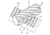
しかも、この種のラックピニオン式ステアリング装置においては、噛合い率を向上して噛合い音を低減できるように、ラック歯およびこれに噛合うピニオン歯がはすばにて構成されている。このために、ラック軸のストロークエンドにおけるラック歯とピニオン歯の噛合いが傾斜した歯面となり、ラック軸に回転モーメントが付与されて、ラック軸のストロークエンドにおける最端の歯に負荷がかかりやすくなる。また、はすばからなるラック歯とピニオン歯を備えたラックピニオン式ステアリング装置においては、ラック軸のストロークエンドにおける最端歯の噛合い長さが小さくなる。すなわち、ラック軸のストロークエンドにおいて、図4に示すように、最端歯のラック歯14aとピニオン歯13aの噛合い部X0が、最端歯を除く歯の噛合い部X1、X2の噛合い長さに対して、極小となる場合がある。加えて、はすばによるラック軸に付与された回転モーメントによって、最端歯の極小の噛合い部に負荷が集中しやすくなる。
In addition, in this type of rack and pinion type steering device, the rack teeth and the pinion teeth that mesh with the rack teeth are formed of a helical so that the meshing rate can be improved and the meshing noise can be reduced. For this reason, the meshing between the rack teeth and the pinion teeth at the stroke end of the rack shaft becomes an inclined tooth surface, and a rotational moment is applied to the rack shaft, so that the endmost tooth at the stroke end of the rack shaft is easily loaded. Become. Further, in the rack and pinion type steering apparatus having rack teeth and pinion teeth made of helical, the meshing length of the outermost teeth at the stroke end of the rack shaft is reduced. That is, at the stroke end of the rack shaft, as shown in FIG. 4, the meshing portion X0 of the
本発明は、上記した従来の問題点を解消するためになされたもので、ラック軸のストロークエンドにおいてピニオン歯に噛合うラック歯の最端歯の歯丈を小さくすることにより、最端歯に作用する曲げモーメントを緩和できるようにしたラックピニオン式ステアリング装置およびそれを備えた電動パワーステアリング装置を提供することを目的とするものである。 The present invention has been made to solve the above-described conventional problems, and by reducing the height of the outermost tooth of the rack tooth that meshes with the pinion tooth at the stroke end of the rack shaft, It is an object of the present invention to provide a rack and pinion type steering device capable of relaxing an acting bending moment and an electric power steering device including the same.
上記の課題を解決するため、請求項1に係るラックピニオン式ステアリング装置の発明の特徴は、はすばからなるラック歯を形成したラック軸と、前記ラック歯に噛合うはすばからなるピニオン歯を形成したピニオン軸を備えたラックピニオン式ステアリング装置において、前記ラック軸のストロークエンドにおいて前記ピニオン歯に噛合うラック歯の最端歯の歯丈を、該最端歯以外の歯丈よりも小さくしたことである。 In order to solve the above-mentioned problem, the invention of the rack and pinion type steering apparatus according to claim 1 is characterized in that a rack shaft formed with helical rack teeth and a helical pinion engaged with the rack teeth. In a rack and pinion type steering apparatus having a pinion shaft formed with teeth, the height of the rack teeth that are engaged with the pinion teeth at the stroke end of the rack shaft is set to be higher than the tooth heights other than the furthest teeth. It is small.
請求項2に係るラックピニオン式ステアリング装置の発明の特徴は、請求項1において、前記最端歯の歯丈を、該最端歯に作用する曲げモーメントを低減できる程度に小さくしたことである。 A feature of the invention of the rack and pinion type steering device according to claim 2 is that, in claim 1, the height of the endmost tooth is made small enough to reduce the bending moment acting on the endmost tooth.
請求項3に係るラックピニオン式ステアリング装置の発明の特徴は、請求項1において、前記最端歯の歯丈を、該最端歯が前記ピニオン歯に噛合わない程度に小さくしたことである。 A feature of the rack and pinion type steering apparatus according to claim 3 is that, in claim 1, the height of the outermost tooth is made small to such an extent that the outermost tooth does not mesh with the pinion tooth.
請求項4に係る電動パワーステアリング装置の発明の特徴は、請求項1ないし請求項3のいずれか1項に記載のラックピニオン式ステアリング装置を備えていることである。 A feature of the electric power steering apparatus according to a fourth aspect is that the rack and pinion type steering apparatus according to any one of the first to third aspects is provided.
請求項1に係るラックピニオン式ステアリング装置の発明によれば、ラック軸のストロークエンドにおいてピニオン歯に噛合うラック歯の最端歯の歯丈を、最端歯以外の歯丈よりも小さくしたので、最端歯に作用する曲げモーメントを緩和することができる。しかも、ラック歯の最端歯の歯丈を小さくした構成であるので、共通のラック軸を歯切り盤等によって製作した後に、ラック歯の最端歯を加工するだけで、必要な歯丈の最端歯を形成でき、ラック軸の製作を容易にすることができる。 According to the invention of the rack and pinion type steering device according to claim 1, the height of the outermost tooth of the rack tooth meshing with the pinion tooth at the stroke end of the rack shaft is made smaller than the tooth height other than the outermost tooth. The bending moment acting on the outermost tooth can be relaxed. Moreover, since the height of the rack teeth at the extreme end is reduced, after the common rack shaft is manufactured with a gear cutter, etc. The outermost teeth can be formed, and the manufacture of the rack shaft can be facilitated.
請求項2に係るラックピニオン式ステアリング装置の発明によれば、最端歯の歯丈を、最端歯に作用する曲げモーメントを低減できる程度に小さくしたので、最端歯に作用する曲げモーメントを低減することができる。 According to the rack and pinion type steering device according to the second aspect of the invention, since the tooth height of the outermost tooth is made small enough to reduce the bending moment acting on the outermost tooth, the bending moment acting on the outermost tooth is reduced. Can be reduced.
請求項3に係るラックピニオン式ステアリング装置の発明によれば、最端歯の歯丈を、最端歯がピニオン歯に噛合わない程度に小さくしたので、最端歯に曲げモーメントを作用させないようにすることができ、ラック軸のストロークエンドにおける衝撃荷重を噛合い長さの大きい他の歯で受けさせることができる。 According to the rack and pinion type steering device of the third aspect of the present invention, since the tooth height of the outermost tooth is reduced to such an extent that the outermost tooth does not mesh with the pinion tooth, no bending moment is applied to the outermost tooth. The impact load at the stroke end of the rack shaft can be received by other teeth having a large meshing length.
請求項4に係る電動パワーステアリング装置の発明によれば、請求項1ないし請求項3のいずれか1項に記載のラックピニオン式ステアリング装置を備えているので、最端歯に作用する曲げモーメントを緩和したり、最端歯に曲げモーメントを作用させなくすることができ、電動パワーステアリング装置の耐久性を向上することができる。しかも、各車種共通のラック軸より最端歯の歯丈を小さくしたラック歯を製作できるので、電動パワーステアリング装置の製作を容易にすることができる。 According to the electric power steering device of the present invention, the rack and pinion type steering device according to any one of claims 1 to 3 is provided, so that the bending moment acting on the endmost teeth is reduced. It is possible to alleviate or to prevent the bending moment from acting on the outermost teeth, and the durability of the electric power steering apparatus can be improved. In addition, since the rack teeth can be manufactured in which the tooth height of the endmost teeth is smaller than the rack shaft common to each vehicle type, the manufacture of the electric power steering device can be facilitated.
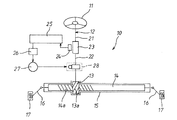
以下本発明の実施の形態を図面に基づいて説明する。図1は、ラックピニオン式ステアリング装置を備えた電動パワーステアリング装置10の模式図を示す。 図1において、電動パワーステアリング装置10は、例えば、コラムアシスト型からなり、ステアリングホイール11に連結されたステアリングシャフト12と、ステアリングシャフト12の先端部に設けられたピニオン軸13と、車両の左右方向に延びるラック軸14と、ピニオン軸13およびラック軸14を支持するハウジング15を備えている。ピニオン軸13は、ハウジング15に回動可能に支持され、ラック軸14は、ハウジング15に直線往復移動可能に支持されている。ピニオン軸13にははすばからなるピニオン歯13aが形成され、このピニオン歯13aに噛合うはすばからなるラック歯14aがラック軸14に形成されている。
Embodiments of the present invention will be described below with reference to the drawings. FIG. 1 is a schematic diagram of an electric
ラック軸14の両端部には、それぞれタイロッド16が結合され、各タイロッド16はナックルアームを介して転舵輪17に連結されている。これにより、ステアリングホイール11が操作されてステアリングシャフト12が回転されると、この回転がピニオン軸13およびラック軸14にて構成されるラックピニオン機構によって、車両の左右方向に沿ったラック軸14の直線運動に変換され、転舵輪17が転舵される。
ステアリングシャフト12は、ステアリングホイール11に連なる筒状の第1操舵軸21と、ピニオン軸13に連なる第2操舵軸22とに分割され、これら第1操舵軸21と第2操舵軸22はトーションバー23を介して同一軸線上で所定角度だけ相対回転可能に連結されている。
The
また、電動パワーステアリング装置10には、第1操舵軸21と第2操舵軸22の相対回転量に基づいて操舵トルクを検出するトルクセンサ24が設けられ、トルクセンサ24のトルク検出信号は制御部25に出力される。制御部25では、トルク検出信号に基づいて、モータ制御ユニット26を介して操舵補助用の電動モータ27への印加電圧を制御する。電動モータ27のモータ軸の回転が、ウォーム減速機構28を介して第2操舵軸22(ピニオン軸13)に伝達され、操舵が補助される。
Further, the electric
ラック軸14は、ハウジング15に対してストロークが規制され、ラック軸14がストロークエンドに達すると、ラック軸14の端部がハウジング15に当接し、ラック軸14の移動が強制的に停止されるようになっている。
The
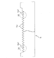
図2は、ラック歯14aを形成したラック軸14を示すもので、ラック軸14は複数の車種に共通に適用できるように、所定歯列のラック歯14aを備えている。すなわち、ラック軸14は、当該ラック軸14を適用する車種のうち、ラック軸14が最大ストロークできるに必要な歯数を備えている。ラック軸14は歯切り盤による歯切り加工等によって各車種共通に製作される。
FIG. 2 shows a
ラック軸14の右ストロークエンドおよび左ストロークエンドにおいてピニオン歯13aに噛合うラック歯14aの最も端部側の歯(以下、これを最端歯と称する)14a1の歯丈H1は、図3に示すように、最端歯14a1以外の歯の歯丈H0に対して小さくされている。
The tooth height H1 of a tooth 14a1 (hereinafter referred to as the most end tooth) of the
すなわち、ラック軸14のストロークエンドにおけるラック歯14aとピニオン歯13aの噛合いにおいて、噛合いに関与しているラック歯14aのうち、ラック歯14aの最端歯14a1を除く歯においては 図4に示すように、噛合い部X1、X2の噛合い長さが大きいのに対し、最端歯14a1においては噛合い部の噛合い長さX0が小さく、場合によっては極小となることがある。このような場合、はすばによってラック軸18が回転することにより、最端歯14a1の小さな噛合い部X0に大きな曲げモーメントが作用する。
That is, in the engagement of the
これを防止するために、本実施の形態においては、最端歯14a1の歯先をフライス加工等によって削りとって、その歯丈H1を小さくすることにより、噛合い長さの大きい他の歯でラック軸14のストロークエンドにおける衝撃荷重を受けさせ、最端歯14a1に大きな曲げモーメントが作用しないようにしている。
In order to prevent this, in the present embodiment, the tip of the outermost tooth 14a1 is scraped off by milling or the like, and the tooth height H1 is reduced so that other teeth having a large meshing length can be used. An impact load at the stroke end of the
この場合、ラック歯14aの最端歯14a1の歯丈H1を、最端歯14a1に作用する曲げモーメントを軽減できる程度に小さくすることにより、最端歯14a1に作用する曲げ応力を軽減することができる。あるいは、ラック歯14aの最端歯14a1の歯丈H1を、最端歯14a1がピニオン歯13aに噛合わないように、大きく切り落とすことにより、最端歯14a1には曲げモーメントを作用させないようにし、代わりに噛合い長さの大きい他の歯で衝撃荷重を受けさせることができる。その結果、衝撃荷重によって最端歯14a1が損傷されることを確実に防止でき、ラックピニオン式ステアリング装置、延いては電動パワーステアリング装置10の耐久性を向上することが可能となる。
In this case, the bending stress acting on the outermost teeth 14a1 can be reduced by reducing the height H1 of the outermost teeth 14a1 of the
なお、ラック軸14は各車種共通で製作されているので、ラック軸14のストロークエンドにおいてピニオン歯13aに噛合うラック歯14aの最端歯14a1は、必ずしも、ラック軸14に形成されたラック歯14の両端に位置する歯ではなく、ラック軸14のストロークに応じて変化する。
Since the
次に、上記した実施の形態における電動パワーステアリング装置10の動作について説明する。ステアリングホイール11を操舵すると、ステアリングシャフト12を介して操舵トルクがピニオン軸13に入力される。ピニオン軸13に入力された操舵トルクは、トルクセンサ24により検出され、検出された操舵トルクに基づいて電動モータ27が回転制御され、操舵補助トルクを発生させる。電動モータ27による操舵補助トルクは、ウォーム減速機構28を介してピニオン軸13に伝達され、ピニオン軸13の回転によりラック軸14が軸方向に移動される。ラック軸14の軸方向移動により、タイロッド16およびナックルアームを介して転舵輪17が転舵され、運転者によるステアリングホイール11の操舵力が軽減される。
Next, the operation of the electric
ところで、ラック軸14のストロークエンドでラック軸14の端部がハウジング15に当接して強制的に停止させられたとき、ピニオン歯13aに噛合うラック歯14aの最端歯14a1には、衝撃荷重によって大きな曲げモーメントが作用するようになる。しかしながら、本実施の形態においては、最端歯14a1の歯丈H1を最端歯14a1以外の歯丈H0よりも小さくしたので、最端歯14a1に作用する曲げモーメントを小さくしたり、最端歯14a1に曲げモーメントを作用させなくすることができる。
By the way, when the end of the
このように、本実施の形態のラックピニオン式ステアリング装置は、ラック歯14aの歯溝は全歯共通で、最端歯14a1の歯丈H1のみ、最端歯14a1以外の歯丈H0よりも小さくした構成であるので、各車種共通のラック軸14を歯切り盤等によって製作した後に、ラック歯14aの最端歯14a1の歯丈を、フライス加工等によって削って小さくすることにより、任意の歯丈H1を容易に形成することができ、ラック軸14の製作を容易に行うことができる。
As described above, in the rack and pinion type steering device of the present embodiment, the gear teeth of the
この際、最端歯14a1の歯丈H1を、最端歯14a1に作用する曲げモーメントを低減できる程度に小さくすることにより、ラック軸14のストロークエンドで最端歯14a1に作用する曲げモーメントを小さくことができる。あるいは、最端歯14a1の歯丈H1を、最端歯14a1がピニオン歯13aに噛合わない程度に小さくすることにより、噛合い長さが不安定な最端歯14a1には曲げモーメントを作用させなくすることができ、噛合い長さの大きい他の歯で衝撃荷重を受けさせることができる。
At this time, by reducing the height H1 of the outermost tooth 14a1 to such an extent that the bending moment acting on the outermost tooth 14a1 can be reduced, the bending moment acting on the outermost tooth 14a1 at the stroke end of the
上記した実施の形態においては、ラックピニオン式ステアリング装置を、コラムアシスト型の電動パワーステアリング装置10に適用した例について述べたが、本発明は、コラムアシスト型に限らず、ラックアシスト型等の電動パワーステアリング装置にも適用可能である。
In the above-described embodiment, the example in which the rack and pinion type steering device is applied to the column assist type electric
以上、本発明を実施の形態に即して説明したが、本発明は実施の形態で述べた構成に限定されるものではなく、特許請求の範囲に記載した本発明の主旨を逸脱しない範囲内で種々の形態を採り得るものである。 Although the present invention has been described with reference to the embodiments, the present invention is not limited to the configurations described in the embodiments, and does not depart from the gist of the present invention described in the claims. It can take various forms.
10・・・電動パワーステアリング装置、13・・・ピニオン軸、13a・・・ピニオン歯、14・・・ラック軸、14a・・・ラック歯、14a1・・・最端歯、15・・・ハウジング、H0、H1・・・歯丈、X0、X1、X2・・・噛合い部。
DESCRIPTION OF
Claims (4)
前記ラック軸のストロークエンドにおいて前記ピニオン歯に噛合うラック歯の最端歯の歯丈を、該最端歯以外の歯丈よりも小さくしたことを特徴とするラックピニオン式ステアリング装置。 In a rack and pinion type steering apparatus comprising a rack shaft formed with helical teeth and a pinion shaft formed with helical pinions engaged with the rack teeth,
A rack-and-pinion type steering device, characterized in that the height of the outermost teeth of the rack teeth meshing with the pinion teeth at the stroke end of the rack shaft is made smaller than the height of the teeth other than the outermost teeth.
An electric power steering apparatus comprising the rack and pinion type steering apparatus according to any one of claims 1 to 3.
Priority Applications (1)
| Application Number | Priority Date | Filing Date | Title |
|---|---|---|---|
| JP2008286198A JP2010111301A (en) | 2008-11-07 | 2008-11-07 | Rack and pinion type steering device, and electric power steering device having the same |
Applications Claiming Priority (1)
| Application Number | Priority Date | Filing Date | Title |
|---|---|---|---|
| JP2008286198A JP2010111301A (en) | 2008-11-07 | 2008-11-07 | Rack and pinion type steering device, and electric power steering device having the same |
Publications (2)
| Publication Number | Publication Date |
|---|---|
| JP2010111301A true JP2010111301A (en) | 2010-05-20 |
| JP2010111301A5 JP2010111301A5 (en) | 2012-09-20 |
Family
ID=42300225
Family Applications (1)
| Application Number | Title | Priority Date | Filing Date |
|---|---|---|---|
| JP2008286198A Pending JP2010111301A (en) | 2008-11-07 | 2008-11-07 | Rack and pinion type steering device, and electric power steering device having the same |
Country Status (1)
| Country | Link |
|---|---|
| JP (1) | JP2010111301A (en) |
Cited By (2)
| Publication number | Priority date | Publication date | Assignee | Title |
|---|---|---|---|---|
| GB2509209A (en) * | 2012-12-21 | 2014-06-25 | Nien Made Entpr Co Ltd | Device for rotating vertical slat blinds, with measures to avoid gear tooth damage |
| EP3056408A1 (en) | 2015-02-12 | 2016-08-17 | Jtekt Corporation | Steering system and rack shaft used for the steering system |
Citations (5)
| Publication number | Priority date | Publication date | Assignee | Title |
|---|---|---|---|---|
| JPS5773268A (en) * | 1980-10-27 | 1982-05-07 | Nippon Seiko Kk | Back of rack-and-pinion type steering device |
| JPH0495571A (en) * | 1990-08-13 | 1992-03-27 | Kayaba Ind Co Ltd | Steering system |
| JPH05250821A (en) * | 1991-07-31 | 1993-09-28 | Sanyo Electric Co Ltd | Feed mechanism |
| JP2006096243A (en) * | 2004-09-30 | 2006-04-13 | Nsk Ltd | Rack and pinion type steering device |
| JP2008137473A (en) * | 2006-12-01 | 2008-06-19 | Nsk Ltd | Rack for steering device |
-
2008
- 2008-11-07 JP JP2008286198A patent/JP2010111301A/en active Pending
Patent Citations (5)
| Publication number | Priority date | Publication date | Assignee | Title |
|---|---|---|---|---|
| JPS5773268A (en) * | 1980-10-27 | 1982-05-07 | Nippon Seiko Kk | Back of rack-and-pinion type steering device |
| JPH0495571A (en) * | 1990-08-13 | 1992-03-27 | Kayaba Ind Co Ltd | Steering system |
| JPH05250821A (en) * | 1991-07-31 | 1993-09-28 | Sanyo Electric Co Ltd | Feed mechanism |
| JP2006096243A (en) * | 2004-09-30 | 2006-04-13 | Nsk Ltd | Rack and pinion type steering device |
| JP2008137473A (en) * | 2006-12-01 | 2008-06-19 | Nsk Ltd | Rack for steering device |
Cited By (7)
| Publication number | Priority date | Publication date | Assignee | Title |
|---|---|---|---|---|
| GB2509209A (en) * | 2012-12-21 | 2014-06-25 | Nien Made Entpr Co Ltd | Device for rotating vertical slat blinds, with measures to avoid gear tooth damage |
| US20140174676A1 (en) * | 2012-12-21 | 2014-06-26 | Nien Made Enterprise Co., Ltd. | Device for adjusting slats of window blind |
| US9133660B2 (en) * | 2012-12-21 | 2015-09-15 | Nien Made Enterprise Co., Ltd. | Device for adjusting slats of window blind |
| GB2509209B (en) * | 2012-12-21 | 2015-09-30 | Nien Made Entpr Co Ltd | Device for adjusting slats of window blind |
| AU2013227991B2 (en) * | 2012-12-21 | 2015-12-03 | Nien Made Enterprise Co., Ltd. | Device for adjusting slats of window blind |
| EP3056408A1 (en) | 2015-02-12 | 2016-08-17 | Jtekt Corporation | Steering system and rack shaft used for the steering system |
| US20160236706A1 (en) * | 2015-02-12 | 2016-08-18 | Jtekt Corporation | Steering system and rack shaft used for the steering system |
Similar Documents
| Publication | Publication Date | Title |
|---|---|---|
| US8434585B2 (en) | Electric power steering system and vehicle steering system | |
| US20090260468A1 (en) | Steering device and movement converting device used therefor | |
| JP2010111301A (en) | Rack and pinion type steering device, and electric power steering device having the same | |
| JP4515834B2 (en) | Electric power steering device | |
| JP2008137473A (en) | Rack for steering device | |
| JP2016016784A (en) | Worm reduction gear and electric power steering device using the same | |
| JP2009073381A (en) | Electric power steering device | |
| JP2009250321A (en) | Gear reduction and electric power steering device equipped with the same | |
| JP2006137256A (en) | Steering device | |
| JP2009126328A (en) | Electric power steering device having worm gear mechanism | |
| JP4049048B2 (en) | Electric power steering device | |
| WO2023042552A1 (en) | Electric power steering device | |
| JP4438565B2 (en) | Rack and pinion steering system | |
| JP2011207381A (en) | Rolling element screw rack gear, and steering device using the same | |
| JP5644408B2 (en) | Electric power steering device | |
| JP2009160960A (en) | Rack-and-pinion type steering device | |
| JP6276926B2 (en) | Double pinion rack bar | |
| JP5636944B2 (en) | Electric power steering device | |
| JP2005007969A (en) | Power steering apparatus | |
| JP2006315603A (en) | Electric power steering device | |
| JP2007196968A (en) | Steering device for vehicle | |
| JP2007050844A (en) | Power steering device | |
| JP2009248690A (en) | Electric power steering device | |
| JP2005233408A (en) | Equipment with gear mechanism | |
| JP2021172203A (en) | Steering device |
Legal Events
| Date | Code | Title | Description |
|---|---|---|---|
| A621 | Written request for application examination |
Free format text: JAPANESE INTERMEDIATE CODE: A621 Effective date: 20110927 |
|
| A521 | Written amendment |
Free format text: JAPANESE INTERMEDIATE CODE: A523 Effective date: 20120718 |
|
| A521 | Written amendment |
Free format text: JAPANESE INTERMEDIATE CODE: A523 Effective date: 20120803 |
|
| A977 | Report on retrieval |
Free format text: JAPANESE INTERMEDIATE CODE: A971007 Effective date: 20121221 |
|
| A131 | Notification of reasons for refusal |
Free format text: JAPANESE INTERMEDIATE CODE: A131 Effective date: 20130226 |
|
| A02 | Decision of refusal |
Free format text: JAPANESE INTERMEDIATE CODE: A02 Effective date: 20130709 |