JP2010107489A5 - - Google Patents
Download PDFInfo
- Publication number
- JP2010107489A5 JP2010107489A5 JP2008289249A JP2008289249A JP2010107489A5 JP 2010107489 A5 JP2010107489 A5 JP 2010107489A5 JP 2008289249 A JP2008289249 A JP 2008289249A JP 2008289249 A JP2008289249 A JP 2008289249A JP 2010107489 A5 JP2010107489 A5 JP 2010107489A5
- Authority
- JP
- Japan
- Prior art keywords
- value
- infrared light
- light source
- concentration
- output
- Prior art date
- Legal status (The legal status is an assumption and is not a legal conclusion. Google has not performed a legal analysis and makes no representation as to the accuracy of the status listed.)
- Granted
Links
- 238000005259 measurement Methods 0.000 claims description 18
- LFQSCWFLJHTTHZ-UHFFFAOYSA-N ethanol Chemical compound CCO LFQSCWFLJHTTHZ-UHFFFAOYSA-N 0.000 claims description 12
- 230000003247 decreasing Effects 0.000 claims 2
- 239000002131 composite material Substances 0.000 claims 1
- 230000001360 synchronised Effects 0.000 claims 1
- 238000010586 diagram Methods 0.000 description 7
- 238000001745 non-dispersive infrared spectroscopy Methods 0.000 description 5
- 230000002238 attenuated Effects 0.000 description 4
- 238000004364 calculation method Methods 0.000 description 4
- 238000000034 method Methods 0.000 description 3
- 230000003287 optical Effects 0.000 description 3
- 238000010521 absorption reaction Methods 0.000 description 2
- 230000003321 amplification Effects 0.000 description 2
- 239000003990 capacitor Substances 0.000 description 2
- 230000001276 controlling effect Effects 0.000 description 2
- 230000000875 corresponding Effects 0.000 description 2
- 238000003199 nucleic acid amplification method Methods 0.000 description 2
- 230000035945 sensitivity Effects 0.000 description 2
- 238000004458 analytical method Methods 0.000 description 1
- 239000000919 ceramic Substances 0.000 description 1
- 230000003111 delayed Effects 0.000 description 1
- 238000007599 discharging Methods 0.000 description 1
- 239000000428 dust Substances 0.000 description 1
- 230000000694 effects Effects 0.000 description 1
- 238000005516 engineering process Methods 0.000 description 1
- 239000002184 metal Substances 0.000 description 1
- 230000005676 thermoelectric effect Effects 0.000 description 1
Images
Description
本発明は、赤外線を用いたCO2ガス濃度測定装置に関するものである。 The present invention relates to a CO2 gas concentration measuring apparatus using infrared rays.
CO2ガス濃度測定は、近年要求が増大している。一般的な技術として、CO2ガスが、赤外線の特定波長を吸収する性質を利用するNDIRと云う方法が用いられる。
図1に、NDIR法の模式図をしめす。図1に示すように、NDIR法は、埃等の侵入を防ぐエアフィルタを通過させた測定空気満たした、セルと称される容器中で、測定動作が行われる。
セルには、赤外線光源(模式図では、IR LAMP)と、赤外線光に受光感度を有する、赤外光受光素子(模式図では、IR DETECTOR)が、設けられている。赤外光受光素子の前面には、、光学フィルター(模式図では、IR Filter)が、設置されている。
CO2が、よく吸収する赤外光波長(4.3μm)の赤外線を選択的に透過する特性の光学的フィルターであり、CO2が吸収する、微小な光量変化を、大きな電圧出力変化にさせるために設けられている。The demand for CO2 gas concentration measurement has been increasing in recent years. As a general technique, a method called NDIR is used in which the CO 2 gas absorbs a specific wavelength of infrared rays.
FIG. 1 shows a schematic diagram of the NDIR method. As shown in FIG. 1, in the NDIR method, a measurement operation is performed in a container called a cell filled with measurement air that has been passed through an air filter that prevents entry of dust and the like.
The cell is provided with an infrared light source (IR LAMP in the schematic diagram) and an infrared light receiving element (IR DETECTOR in the schematic diagram) having light receiving sensitivity to the infrared light. An optical filter (in the schematic diagram, an IR filter) is installed on the front surface of the infrared light receiving element.
CO2 is an optical filter with a characteristic of selectively transmitting infrared light with a wavelength of infrared light (4.3 μm) that is well absorbed, so that the minute change in the amount of light absorbed by CO2 can be changed to a large voltage output change. Is provided.
赤外線光源から、出された赤外光は、空気中のCO2により吸収されるが、吸収の度合いにより、、赤外線受光素子出力が、減衰する。赤外線受光素子出力の大きさを評価する事で、空気中のCO2の量、CO2濃度を知る事が、可能となる。
赤外線光受光素子が直流的出力を出す素子であれば、受光素子出力を、安定性の有る直流増幅を行う事で、赤外線光受光素子の、出力変動を安定して、知る事が、可能となり、空気中のCO2濃度測定を安定して、行う事が、可能である。。Infrared light emitted from the infrared light source is absorbed by CO2 in the air, but the infrared light receiving element output is attenuated depending on the degree of absorption. By evaluating the magnitude of the infrared light receiving element output, it is possible to know the amount of CO2 in the air and the CO2 concentration.
If the infrared light receiving element is an element that outputs a direct current, the output fluctuation of the infrared light receiving element can be known stably by performing stable direct current amplification of the light receiving element output. It is possible to stably measure the CO2 concentration in the air. .
(受光素子の選択)
前記により、安定した赤外線受光素子出力を安定した増幅器で増幅することが、安定した、CO2濃度測定に重要である事が、分る。
一方、赤外線受光素子としては、サーモパイル(熱電堆素子)、パイロ(焦電素子)が、知られている。(Selection of light receiving element)
From the above, it can be seen that amplifying a stable infrared light receiving element output with a stable amplifier is important for stable CO2 concentration measurement.
On the other hand, thermopile (thermopile element) and pyro (pyroelectric element) are known as infrared light receiving elements.
(サーモパイル)
サーモパイルは、熱電対を、束ねた構造の赤外線受光素子であり、多数の熱電対を束ねることにより、出力値を大きくしたものである。原理的には、赤外光の熱作用に反応するものであり、赤外光強度(熱強度)に対する出力値であり、熱強度に比例した、直流出力のため、直流増幅器により、出力はそのままCO2濃度測定データとして使用可能である。赤外線方式CO2濃度計の赤外線受光素子としての使用歴は、古く、広く使用されている。多数の熱電対を束ねた構造で、比較的出力は大きくなっているが、出力絶対値は、微小であり、直流増幅器としては、安価な供給の増幅器の使用は望み難い状況である。(Thermopile)
The thermopile is an infrared light receiving element having a structure in which thermocouples are bundled, and an output value is increased by bundling a large number of thermocouples. In principle, it reacts to the thermal action of infrared light, and is an output value with respect to infrared light intensity (heat intensity). Since it is a direct current output proportional to the heat intensity, the output is directly output by a direct current amplifier. It can be used as CO2 concentration measurement data. The use history of the infrared CO2 concentration meter as an infrared light receiving element is old and widely used. Although the output is relatively large with a structure in which a large number of thermocouples are bundled, the absolute value of the output is very small, and it is difficult to use a cheaply supplied amplifier as a DC amplifier.
(パイロ(焦電素子))
パイロ素子は、セラミック素子であり、赤外光による光電効果で、出力電圧を発生するものであり、「金属の熱電効果による熱起電力発生」を用いる、サーモパイルとは、異なる。サーモパイルとの大きな相違は、赤外光に対して、高感度であり、出力値も大きく、増幅器は、交流増幅で可能あり、増幅器の安価な供給が可能である。ただ、増幅器が、安価な供給可能な反面、赤外光受光入力の変化分に反応するタイプ、変化分対応受光素子であり、直流的な入光には、反応しない。このため、CO2濃度測定のような、直流的赤外光入光信号の処理には、信号処理に、工夫が必要であり、困難さを伴なう。サーモパイルのように、直流アンプのみで、増幅信号を得る事は、不可能であり、一般的機器には、マイコンを使用した、構成となり、低価格化の障害と、なっていた。このため、低価格CO2濃度計への応用は遅れている。(Pyro (pyroelectric element))
The pyro element is a ceramic element, which generates an output voltage by a photoelectric effect by infrared light, and is different from a thermopile using “generation of thermoelectromotive force by a thermoelectric effect of metal”. The major difference from the thermopile is high sensitivity to infrared light and a large output value. The amplifier can be AC amplified, and the amplifier can be supplied at low cost. However, while the amplifier can be supplied at a low cost, it is a type that responds to a change in the infrared light receiving input and a light receiving element corresponding to the change, and does not react to direct current light. For this reason, the processing of the DC infrared light incident signal such as the measurement of the CO2 concentration requires a contrivance in the signal processing and is accompanied by difficulty. Like a thermopile, it is impossible to obtain an amplified signal using only a DC amplifier, and a general device uses a microcomputer, which is an obstacle to lowering the price. For this reason, application to a low-cost CO2 concentration meter is delayed.
[特許文献1]に於いては、赤外線受光素子として、直流出力の、サーモパイル使用を主として記さあれている。変化分出力のパイロ素子(焦電素子)も使用可と、記されているが、、具体的記載は、無い。[Patent Document 1] mainly describes the use of a thermopile with a direct current output as an infrared light receiving element. Although it is described that a pyro element (pyroelectric element) of change output can be used, there is no specific description.
当申請書記載の本発明は、赤外線受光素子にパイロ素子を用いて、マイコン等不使用で、安価に対応可能な、増幅・信号処理を可能にする方式を提供するための、考案であり、パイロ素子を使用した赤外線応用CO2濃度計の低価格化・高性能化に寄与するものである。勿論、マイコンを使用した場合にも、問題無く使用可能である。The present invention described in this application is a device for providing a method that enables amplification and signal processing using a pyro element as an infrared light receiving element, not using a microcomputer, and corresponding to low cost, This contributes to lowering the price and improving the performance of infrared application CO2 concentration meters using pyro elements. Of course, even if a microcomputer is used, it can be used without any problem.
上記課題を解決する為に為された、請求項1記載の発明は、パイロ素子出力信号処理を、マイコン不使用、汎用ディスクリートIC使用による、CO2センサー供給を可能にするものである。 The invention according to claim 1, which has been made to solve the above-described problems, makes it possible to supply a CO 2 sensor by using a pyro element output signal process without using a microcomputer and using a general-purpose discrete IC.
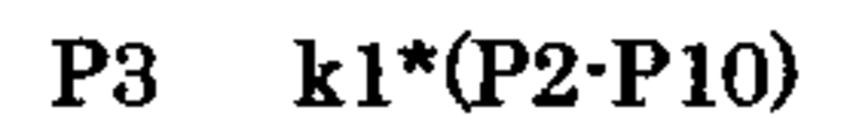
赤外線光源に白熱ランプを用い、赤外線受光素子に焦電素子を用いて構成したNDIR方式赤外線CO2濃度計において、一定周期で赤外線光源を点灯させ、該赤外線光源から発光される赤外光は、CO2濃度測定対象空気中のCO2により、赤外光吸収を受け、減衰し、受光素子に照射され、受光素子は、光電信号を、出力し、該光電信号は、増幅器に入力され、増幅光電信号P2(図2e1)となる。 In an NDIR infrared CO2 densitometer configured using an incandescent lamp as an infrared light source and a pyroelectric element as an infrared light receiving element, the infrared light source is turned on at a constant period, and the infrared light emitted from the infrared light source is CO2 Infrared light is absorbed and attenuated by CO2 in the concentration measurement target air, irradiated to the light receiving element, the light receiving element outputs a photoelectric signal, the photoelectric signal is input to the amplifier, and the amplified photoelectric signal P2 (FIG. 2e1).
一方、測定タイミングTnで、赤外線光源が、非点灯から、点灯と変化した時、赤外線光源点灯による赤外線光源光量増加で、赤外線受光素子の増幅光電信号出力P2は、図2eに示されるように増加するが、その増加分波形をP10(図2e2)とした時、P10は、CO2測定対象空気中のCO2濃度により、赤外線吸収の度合いが異なり、波高値は、変化する。
つまり、P10は、測定対象空気中のCO2濃度が高いと、赤外線光源からの、赤外光は、測定対象空気中のCO2により、より大きく吸収され、、受光素子に達する赤外光量は、低下し、波高値は低くなる。この波形、P10を、含んだ以下の式▲1▼の値をP3とし、
P3=k1×(k2−P10)=k3−k1P10・・・式▲1▼
式▲1▼のP3値により、空気中のCO2濃度を得る事が可能となる。On the other hand, when the infrared light source changes from non-lighting to lighting at the measurement timing Tn, the amplified photoelectric signal output P2 of the infrared light receiving element increases as shown in FIG. However, when the increased waveform is P10 (FIG. 2e2), the degree of infrared absorption of P10 varies depending on the CO2 concentration in the CO2 measurement target air, and the peak value changes.
That is, when the CO2 concentration in the measurement target air is high in P10, the infrared light from the infrared light source is more absorbed by the CO2 in the measurement target air, and the amount of infrared light reaching the light receiving element is reduced. However, the peak value becomes low. The value of the following formula (1) including this waveform, P10, is P3,
P3 = k1 × (k2-P10) = k3-k1P10 Formula (1)
It is possible to obtain the CO2 concentration in the air by the P3 value of the equation (1).
式▲1▼により、得られる値、P3値は、縦軸をP3値、横軸を赤外線光源点灯後の時間経過を示す、図2dの変化となる。図2dの最小値(ボトムピーク値、P3−BP)は、赤外線光源の光量が、ランプフィラメントにランプ点灯電圧印加後、最大光量となり、それに伴いパイロ素子光電出力が、増加し、ピーク値となる時と関係している。この、P3ボトムピーク値が、測定タイミングTnに於けるガス濃度測定値(未較正値)する事の合理性は、見られる。
この未較正値を、請求項3の方法により、較正を行えば、測定ガス濃度値較正値なる。The value P3 obtained by equation (1) is the change in FIG. 2d, in which the vertical axis indicates the P3 value and the horizontal axis indicates the time elapsed after the infrared light source is turned on. The minimum value (bottom peak value, P3-BP) in FIG. 2d is that the light amount of the infrared light source becomes the maximum light amount after the lamp lighting voltage is applied to the lamp filament, and the pyro element photoelectric output increases accordingly and becomes the peak value. It has to do with time. The rationality that this P3 bottom peak value is the gas concentration measurement value (uncalibrated value) at the measurement timing Tn can be seen.
If this uncalibrated value is calibrated by the method of claim 3, it becomes a measured gas concentration value calibration value.
式▲1▼から、CO2濃度値を得る動作は、[請求項1[請求項2]]の動作により可能となる。
赤外線光源(白熱ランプ)を一定周期で点灯させ、赤外線光学フィルター付き赤外線受光素子(パイロ素子)で受光し、赤外線光源と受光素子間の、空気中のCO2濃度を測定するNDIR方式CO2濃度センサーに於いて、
赤外線受光素子出力信号のうち、
赤外線光源のみによる、出力をP10とし、
P3=k1×(k2−P10)・・・式▲1▼
式▲1▼で得られるP3測定値を、請求項2では、予め初期値を0として置いた置数器P13置数と、比較し、
(測定値)P3≧(置数器値)P13の場合は、
置数器値P13の値に応じ決められた数式で求まる値にP13値を置数変更し、
(測定値)P3≦(値数器値)P13の場合は、
置数器値P13の値に一致させる事で、当該測定値を得る事が可能となる。The operation of obtaining the CO2 concentration value from the equation (1) is enabled by the operation of [Claim 1 [Claim 2]].
An NDIR CO2 concentration sensor that turns on an infrared light source (incandescent lamp) at regular intervals, receives light with an infrared light receiving element (pyro element) with an infrared optical filter, and measures the CO2 concentration in the air between the infrared light source and the light receiving element. In
Among infrared light receiving element output signals,
The output from only the infrared light source is P10,
P3 = k1 × (k2−P10) (1)
In the second aspect, the measured P3 value obtained by the equation (1) is compared with the numerator P13 numerator in which the initial value is set to 0 in advance.
(Measurement value) P3 ≧ (Numerical value) P13,
The P13 value is changed to a value obtained by a mathematical formula determined according to the value of the register value P13,
In the case of (measured value) P3 ≦ (value counter value) P13,
By making it coincide with the value of the register value P13, the measured value can be obtained.
前述のように、式▲1▼で表されるP3信号値は、関係式中に、赤外線受光素子出力信号のうち、赤外線光源のみによる、光電出力P10値は、空気中のCO2ガスにより赤外線吸収を受けた結果の光量値情報であるP10値を、含んでいるために、空気中のCO2ガス濃度を示すものとなる。
式▲1▼中の、P10値を用いて、CO2ガス濃度値を表現可能な事は、P10値、1点の情報で、CO2濃度値表現可能な事を意味し、環境要素、周囲温度値を包含した測定値を得る事が、可能となり、演算処理の簡素化をもたらす。As described above, the P3 signal value represented by the formula (1) is the infrared light receiving element output signal of the infrared light receiving element output signal, and the photoelectric output P10 value is absorbed by the CO2 gas in the air. Since it includes the P10 value that is the light quantity value information obtained as a result of the reception, it indicates the CO2 gas concentration in the air.
The ability to express the CO2 gas concentration value using the P10 value in equation (1) means that the CO2 concentration value can be expressed with the P10 value and one point of information. It is possible to obtain a measurement value that includes, thereby simplifying the arithmetic processing.
演算処理に、マイコンを用いる場合で、式▲1▼を用いた演算方法で無くても、P3波形を、多点値取り込む方式で、波形解析を行う方法で、CO2濃度値を、得る事は、可能であるが、式▲1▼を用いる方法は、取り込む情報は、P3値、1点のみで用を足りることと比較すれば、「多点情報」と「1点情報」の違いは大きく、コストの差として、顕著なものとなる。In the case of using a microcomputer for the calculation process, it is not possible to obtain the CO2 concentration value by the method of waveform analysis with the method of taking in the multipoint value of the P3 waveform even if the calculation method using the formula (1) is not used. Although the method using the formula (1) is possible, the difference between “multi-point information” and “single-point information” is large when compared with the fact that the information to be captured is sufficient with only the P3 value and one point. As a difference in cost, it becomes remarkable.
図3に実施の、使用例回路をしめす。図3の使用例回路では、マイコンを使用せず、低価格な、アンプを用いた回路であり、部品数は、少なく構成されている。 FIG. 3 shows an example circuit of the implementation. The use example circuit of FIG. 3 is a circuit using an amplifier that does not use a microcomputer and is inexpensive, and has a small number of components.
以下、、本発明の実施の形態を、図3実施回路例により、示す。 Hereinafter, an embodiment of the present invention will be described with reference to FIG.
図3実施回路例に於いては、式▲1▼は、図3中のアンプU2の出力、U2−14が、式▲1▼出力P3に相当し、該アンプ入力として、空気中のCO2による赤外線吸収を受け、減衰した赤外光を受光した、受光素子出力(P10)が、入力されている。
一方、置数器として用いている容量C1電圧値は、バッファアンプ出力U2−1、P13として使用され、前出P3とP13を、比較器で比較し、アンプ出力P11、(U2−8)を得る。
P11は、置数器C1の置数置の増減を制御する。In the circuit example shown in FIG. 3, the expression {circle around (1)} is the output of the amplifier U2 in FIG. 3 and U2-14 corresponds to the expression {circle around (1)} output P3. A light receiving element output (P10) that receives infrared light attenuated and attenuated infrared light is input.
On the other hand, the capacitance C1 voltage value used as a register is used as buffer amplifier outputs U2-1 and P13. The above-mentioned P3 and P13 are compared by a comparator, and the amplifier outputs P11 and (U2-8) are compared. obtain.
P11 controls the increase / decrease of the number place of the place number device C1.
U2−8=P11の極性の正・負により、P13値の増大・減少を制御する事で、CO2濃度の演算を行い、容量C1の電圧値として保存し、測定濃度値を得る事が可能となる。 By controlling the increase / decrease of the P13 value according to the positive / negative polarity of U2-8 = P11, it is possible to calculate the CO2 concentration, save it as the voltage value of the capacitor C1, and obtain the measured concentration value Become.
置数器として用いる容量C1の充電値の増減は、C1への充電動作が、充電値=濃度値の増大、C1の放電動作が、充電値=濃度値の減少となる。
実施例に於いては、充電は、内部低電圧で、常時行い、放電を、P11極性で、制御している。As for the increase or decrease of the charge value of the capacitor C1 used as a register, the charge operation to C1 is an increase in charge value = concentration value and the discharge operation of C1 is a decrease in charge value = concentration value.
In the embodiment, charging is always performed with an internal low voltage, and discharging is controlled with P11 polarity.
CO2濃度値は、赤外線光源点灯毎に、測定値として、容量C1電圧値として、保存され、P13=CO2濃度値として使用可能であるが、実際のCO2濃度と容量C1電圧値の較正値を、得たい場合は、可変倍率演算を行う演算増幅器(アンプ出力U2−7)を介することで、較正値を得る事が可能となる。([請求項3]) The CO2 concentration value is stored as a capacitance C1 voltage value as a measurement value every time the infrared light source is turned on and can be used as P13 = CO2 concentration value. However, the calibration value of the actual CO2 concentration and the capacitance C1 voltage value is If it is desired to obtain, a calibration value can be obtained through an operational amplifier (amplifier output U2-7) that performs variable magnification calculation. ([Claim 3])
マイコンを用いた演算で実行させる場合は、置数器、容量C1を、
ディジタルレジスタとし、P3,P13の比較演算をディジタル演算で行い、置数器増減をディジタル制御とすれば同様な結果を得る事が、可能である。In the case of executing by calculation using a microcomputer, the register and the capacity C1 are
It is possible to obtain a similar result by using a digital register, performing the comparison operation of P3 and P13 by digital operation, and digitally controlling the increase / decrease of the number of registers.
前述の動作により、得られるCO2濃度値は、低価格な構成により、
CO2濃度を、得る事が可能となり、CO2濃度測定の応用分野を拡大させる事に寄与するものである。By the above operation, the obtained CO2 concentration value can be obtained by a low-cost configuration.
This makes it possible to obtain the CO2 concentration and contributes to expanding the application field of CO2 concentration measurement.
E3 Charg Voltage
P11 discharge control 測定濃度値、P13の増減を行なう。
P2 受光素子出力波形P2e
P10 受光素子出力赤外光成分波形P10e
![]()
P11 discharge control Increase or decrease the measured concentration value, P13.
P2 Light receiving element output waveform P2e
P10 Light-receiving element output infrared light component waveform P10e
![]()
Claims (3)
P3=k1−k2×P10n
で得られる、電圧値、P3値は、既知濃度値のCO2ガスで、校正されている場合、赤外線光源白熱ランプの、点灯時遅れ時間を伴うフィラメント発光量特性と、受光量変化分のみを出力するパイロ素子出力の合成応答特性から成る、負方向のピーク電圧値を示す多次元函数曲線と成り、該負方向のピーク電圧値が、赤外線光源と、パイロ素子間の空気中の、校正されたCO2濃度値を示す事から、P3負方向ピーク電圧値測定により、空気中のCO2濃度値を得る事を特徴とするCO2センサ。An infrared light source is turned on by an infrared light source lighting signal PLn output continuously at a constant time interval, and after the infrared light emitted by the lighting is transmitted through air, an infrared light receiving element, a pyro When the light receiving signal P2 is received by the element and only the change at the time of projecting the infrared light is P10n, and the signal obtained by the synchronous rectification is P10n, the arithmetic expression P3 = k1−k2 × P10n
When the voltage value and P3 value obtained in step 2 are calibrated with CO2 gas of a known concentration value, only the light emission amount characteristic and the amount of change in the amount of received light of the infrared light source incandescent lamp with a delay time at lighting are output. A multi-dimensional function curve indicating a negative peak voltage value composed of a composite response characteristic of the pyro element output, and the negative peak voltage value is calibrated in the air between the infrared light source and the pyro element. A CO2 sensor characterized by obtaining a CO2 concentration value in air by measuring a P3 negative direction peak voltage value because it indicates a CO2 concentration value.
Priority Applications (1)
| Application Number | Priority Date | Filing Date | Title |
|---|---|---|---|
| JP2008289249A JP4805996B2 (en) | 2008-10-15 | 2008-10-15 | CO2 gas concentration measuring device using infrared rays |
Applications Claiming Priority (1)
| Application Number | Priority Date | Filing Date | Title |
|---|---|---|---|
| JP2008289249A JP4805996B2 (en) | 2008-10-15 | 2008-10-15 | CO2 gas concentration measuring device using infrared rays |
Publications (3)
| Publication Number | Publication Date |
|---|---|
| JP2010107489A JP2010107489A (en) | 2010-05-13 |
| JP2010107489A5 true JP2010107489A5 (en) | 2010-07-15 |
| JP4805996B2 JP4805996B2 (en) | 2011-11-02 |
Family
ID=42297057
Family Applications (1)
| Application Number | Title | Priority Date | Filing Date |
|---|---|---|---|
| JP2008289249A Expired - Fee Related JP4805996B2 (en) | 2008-10-15 | 2008-10-15 | CO2 gas concentration measuring device using infrared rays |
Country Status (1)
| Country | Link |
|---|---|
| JP (1) | JP4805996B2 (en) |
Family Cites Families (3)
| Publication number | Priority date | Publication date | Assignee | Title |
|---|---|---|---|---|
| JPS62218826A (en) * | 1986-03-20 | 1987-09-26 | Sanyo Electric Co Ltd | Infrared detector |
| JPH1021479A (en) * | 1996-06-28 | 1998-01-23 | Matsushita Electric Works Ltd | Photoelectric transduction circuit |
| JP2004020556A (en) * | 2002-06-14 | 2004-01-22 | Noboru Hasebe | Peak hold circuit in carbon dioxide sensor |
-
2008
- 2008-10-15 JP JP2008289249A patent/JP4805996B2/en not_active Expired - Fee Related
Similar Documents
| Publication | Publication Date | Title |
|---|---|---|
| KR101779761B1 (en) | Temperature compensation thermometer and method using a distance measuring seneor | |
| JP2013545094A5 (en) | ||
| CN101701850B (en) | Method for detecting temperature and blackness of flame | |
| GB2454761A (en) | Infrared target temperature correction system and method | |
| US9835604B2 (en) | Temperature compensation of gas sensors | |
| CN103335717A (en) | High-precision temperature-drift resistance temperature measurement method for thermal infrared imager based on variable integral mode | |
| JP6113080B2 (en) | System and method for performing heaterless lead selenide-based capnometry and / or capnography | |
| CN103557965A (en) | Method for measuring temperature of rotary cement kiln and method and device for online detection of temperature field of rotary cement kiln | |
| Tschudi et al. | Measuring temperatures in the presence of external radiation by flash assisted multiwavelength pyrometry | |
| JP2006513424A (en) | High precision gas energy meter | |
| JP2010107489A5 (en) | ||
| JP2010107489A (en) | Infrared co2 densitometer with pyroelectric element used as photodetector | |
| JPH0235322A (en) | Radiation clinical thermometer | |
| JP2008292321A (en) | Gas concentration measuring instrument | |
| CN104180927B (en) | Measurement platform and measurement method for standard temperature of super-high-temperature hearth | |
| CN203719793U (en) | On-line detection device for temperature field of rotary cement kiln | |
| CN110361518B (en) | On-line monitoring system for fuel entering furnace for low-calorific-value coal power generation | |
| RU84986U1 (en) | DEVICE FOR SIMULTANEOUS DETERMINATION OF THE CONCENTRATION OF CO AND CO2 MOLECULES IN A GAS-MEDIUM | |
| JP6353227B2 (en) | Gas sensor control device and infrared analysis type gas concentration detection device | |
| JP2014186000A (en) | Quantum type infrared gas densitometer | |
| CN214066923U (en) | Non-dispersive infrared long optical path measuring cell combined gas measuring system | |
| WO2024013293A1 (en) | Detector with temperature drift compensation | |
| KR100508912B1 (en) | High speed gas concentration measuring apparatus based of electrical chopped emitter and semiconductor detector | |
| RU138046U1 (en) | OPTICAL RADIOMETER | |
| RU77423U1 (en) | RADIATION THERMOMETER |