JP2010104168A - Power unit and power system for fuel cell vehicle - Google Patents

Power unit and power system for fuel cell vehicle Download PDF

Info

Publication number
JP2010104168A
JP2010104168A JP2008274306A JP2008274306A JP2010104168A JP 2010104168 A JP2010104168 A JP 2010104168A JP 2008274306 A JP2008274306 A JP 2008274306A JP 2008274306 A JP2008274306 A JP 2008274306A JP 2010104168 A JP2010104168 A JP 2010104168A
Authority
JP
Japan
Prior art keywords
fuel cell
power
cell stack
line
target
Prior art date
Legal status (The legal status is an assumption and is not a legal conclusion. Google has not performed a legal analysis and makes no representation as to the accuracy of the status listed.)
Pending
Application number
JP2008274306A
Other languages
Japanese (ja)
Other versions
JP2010104168A5 (en
Inventor
Toshihiro Sone
利浩 曽根
Current Assignee (The listed assignees may be inaccurate. Google has not performed a legal analysis and makes no representation or warranty as to the accuracy of the list.)
Honda Motor Co Ltd
Original Assignee
Honda Motor Co Ltd
Priority date (The priority date is an assumption and is not a legal conclusion. Google has not performed a legal analysis and makes no representation as to the accuracy of the date listed.)
Filing date
Publication date
Application filed by Honda Motor Co Ltd filed Critical Honda Motor Co Ltd
Priority to JP2008274306A priority Critical patent/JP2010104168A/en
Publication of JP2010104168A publication Critical patent/JP2010104168A/en
Publication of JP2010104168A5 publication Critical patent/JP2010104168A5/ja
Pending legal-status Critical Current

Links

Images

Classifications

    • YGENERAL TAGGING OF NEW TECHNOLOGICAL DEVELOPMENTS; GENERAL TAGGING OF CROSS-SECTIONAL TECHNOLOGIES SPANNING OVER SEVERAL SECTIONS OF THE IPC; TECHNICAL SUBJECTS COVERED BY FORMER USPC CROSS-REFERENCE ART COLLECTIONS [XRACs] AND DIGESTS
    • Y02TECHNOLOGIES OR APPLICATIONS FOR MITIGATION OR ADAPTATION AGAINST CLIMATE CHANGE
    • Y02EREDUCTION OF GREENHOUSE GAS [GHG] EMISSIONS, RELATED TO ENERGY GENERATION, TRANSMISSION OR DISTRIBUTION
    • Y02E60/00Enabling technologies; Technologies with a potential or indirect contribution to GHG emissions mitigation
    • Y02E60/30Hydrogen technology
    • Y02E60/50Fuel cells
    • YGENERAL TAGGING OF NEW TECHNOLOGICAL DEVELOPMENTS; GENERAL TAGGING OF CROSS-SECTIONAL TECHNOLOGIES SPANNING OVER SEVERAL SECTIONS OF THE IPC; TECHNICAL SUBJECTS COVERED BY FORMER USPC CROSS-REFERENCE ART COLLECTIONS [XRACs] AND DIGESTS
    • Y02TECHNOLOGIES OR APPLICATIONS FOR MITIGATION OR ADAPTATION AGAINST CLIMATE CHANGE
    • Y02TCLIMATE CHANGE MITIGATION TECHNOLOGIES RELATED TO TRANSPORTATION
    • Y02T10/00Road transport of goods or passengers
    • Y02T10/60Other road transportation technologies with climate change mitigation effect
    • Y02T10/70Energy storage systems for electromobility, e.g. batteries
    • YGENERAL TAGGING OF NEW TECHNOLOGICAL DEVELOPMENTS; GENERAL TAGGING OF CROSS-SECTIONAL TECHNOLOGIES SPANNING OVER SEVERAL SECTIONS OF THE IPC; TECHNICAL SUBJECTS COVERED BY FORMER USPC CROSS-REFERENCE ART COLLECTIONS [XRACs] AND DIGESTS
    • Y02TECHNOLOGIES OR APPLICATIONS FOR MITIGATION OR ADAPTATION AGAINST CLIMATE CHANGE
    • Y02TCLIMATE CHANGE MITIGATION TECHNOLOGIES RELATED TO TRANSPORTATION
    • Y02T10/00Road transport of goods or passengers
    • Y02T10/60Other road transportation technologies with climate change mitigation effect
    • Y02T10/72Electric energy management in electromobility

Abstract

<P>PROBLEM TO BE SOLVED: To reduce cost required for configuration and reduce the size. <P>SOLUTION: A power unit 10 includes: first to third lines L1, L2 and L3, which are different in potential; a battery circuit 10a, in which a fuel cell stack 11 and a battery 12 are connected in series; and the first DC-DC converter 13. Both ends of the battery circuit 10a are connected to the first line L1 and the third line L3, and a connection point between the fuel cell stack 11 and the battery 12 is connected to the second line L2, and the primary side of the first DC-DC converter 13 is connected to the second line L2 and the third line L3, while the secondary side is connected to the first line L1 and the third line L3. The switching duty of the first DC-DC converter 13 is feedback-controlled so that an actual power distribution to the fuel cell stack 11 and the battery 12 matches the target power distribution when driving a drive motor inverter 15 which is connected to the first line L1 and the third line L3. <P>COPYRIGHT: (C)2010,JPO&INPIT

Description

この発明は、電源装置および燃料電池車両の電源システムに関する。   The present invention relates to a power supply device and a power supply system for a fuel cell vehicle.

従来、例えば燃料電池に接続された第1DC−DCコンバータと、蓄電装置に接続された第2DC−DCコンバータとを備え、2つの第1および第2DC−DCコンバータから車両駆動用電動機などの負荷に電力を供給する電源システムが知られている(例えば、特許文献1参照)。
特開2007−318938号公報
2. Description of the Related Art Conventionally, for example, a first DC-DC converter connected to a fuel cell and a second DC-DC converter connected to a power storage device are provided, and a load such as a vehicle driving motor is provided from the two first and second DC-DC converters. A power supply system that supplies power is known (see, for example, Patent Document 1).
JP 2007-318938 A

ところで、上記従来技術に係る電源システムにおいては、複数の電源(つまり、燃料電池および蓄電装置)毎にDC−DCコンバータを備えることに起因して、電源システムの構成に要する費用が嵩むとともに、電源システムのサイズが増大してしまうという問題が生じることから、費用の削減およびサイズの小型化が望まれている。   By the way, in the power supply system according to the above prior art, the cost required for the configuration of the power supply system increases due to the provision of the DC-DC converter for each of the plurality of power supplies (that is, the fuel cell and the power storage device). Due to the problem of increasing the size of the system, cost reduction and size reduction are desired.

本発明は上記事情に鑑みてなされたもので、構成に要する費用を削減すると共にサイズを小型化することが可能な電源装置および燃料電池車両の電源システムを提供することを目的としている。   The present invention has been made in view of the above circumstances, and an object of the present invention is to provide a power supply apparatus and a power supply system for a fuel cell vehicle that can reduce the cost required for the configuration and reduce the size.

上記課題を解決して係る目的を達成するために、本発明の第1態様に係る電源装置(例えば、実施の形態での電源装置10)は、電位の異なる第1ライン(例えば、実施の形態での第1ラインL1)および第2ライン(例えば、実施の形態での第2ラインL2)および第3ライン(例えば、実施の形態での第3ラインL3)と、燃料電池スタック(例えば、実施の形態での燃料電池スタック11)と蓄電装置(例えば、実施の形態でのバッテリ12)とが直列に接続されてなる電池回路(例えば、実施の形態での電池回路10a)と、DC−DCコンバータ(例えば、実施の形態での第1DC−DCコンバータ13)とを備え、前記電池回路の両端は前記第1ラインと前記第3ラインとに接続され、前記電池回路の前記燃料電池スタックと前記蓄電装置との接続点は前記第2ラインに接続され、前記DC−DCコンバータの1次側は前記第2ラインと前記第3ラインとに接続され、前記DC−DCコンバータの2次側は前記第1ラインと前記第3ラインとに接続され、前記第1ラインおよび前記第3ラインから負荷に電力を供給しており、前記負荷の消費電力を取得する消費電力取得手段(例えば、実施の形態での消費電力算出部61)と、前記消費電力に基づいて前記燃料電池スタックと前記蓄電装置との目標電力配分を設定する目標電力配分設定手段(例えば、実施の形態での目標電力配分設定部62)と、前記燃料電池スタックと前記蓄電装置との実電力配分が前記目標電力配分に一致するようにして前記DC−DCコンバータのスイッチングデューティーを制御するデューティー制御手段(例えば、実施の形態でのデューティー制御部64)とを備える。   In order to solve the above-described problems and achieve the object, the power supply apparatus according to the first aspect of the present invention (for example, the power supply apparatus 10 in the embodiment) has a first line having a different potential (for example, the embodiment). The first line L1) and the second line (eg, the second line L2 in the embodiment) and the third line (eg, the third line L3 in the embodiment) and the fuel cell stack (eg, the implementation) A battery circuit (for example, the battery circuit 10a in the embodiment) in which the fuel cell stack 11) and the power storage device (for example, the battery 12 in the embodiment) are connected in series, and a DC-DC Converter (for example, the first DC-DC converter 13 in the embodiment), both ends of the battery circuit are connected to the first line and the third line, and the fuel cell stack of the battery circuit and the front The connection point with the power storage device is connected to the second line, the primary side of the DC-DC converter is connected to the second line and the third line, and the secondary side of the DC-DC converter is the above-mentioned A power consumption acquisition means (for example, an embodiment) connected to the first line and the third line, supplying power to the load from the first line and the third line, and acquiring the power consumption of the load Power consumption calculation unit 61) and target power distribution setting means for setting target power distribution between the fuel cell stack and the power storage device based on the power consumption (for example, target power distribution setting unit in the embodiment) 62) and a duty cycle for controlling the switching duty of the DC-DC converter so that the actual power distribution between the fuel cell stack and the power storage device matches the target power distribution. Comprising I-controlled unit (e.g., a duty control unit 64 in the embodiment) and a.

さらに、本発明の第2態様に係る電源装置では、前記消費電力取得手段は、前記電源装置の外部の負荷(例えば、実施の形態での駆動モータ22および空調機器24および車両用補機など)の外部負荷消費電力と前記電源装置の内部の負荷(例えば、実施の形態でのエアポンプインバータ14など)の内部負荷消費電力とを含む前記消費電力を取得する。   Furthermore, in the power supply device according to the second aspect of the present invention, the power consumption acquisition means is a load external to the power supply device (for example, the drive motor 22, the air conditioner 24, and the vehicle auxiliary machine in the embodiment). The external power consumption of the power supply device and the internal load power consumption of the internal load of the power supply device (for example, the air pump inverter 14 in the embodiment) are acquired.

さらに、本発明の第3態様に係る電源装置は、前記目標電力配分に基づき前記燃料電池スタックまたは前記蓄電装置の目標電流を設定する目標電流設定手段(例えば、実施の形態での目標電流設定部63)を備え、前記デューティー制御手段は、前記燃料電池スタックまたは前記蓄電装置の実電流が前記目標電流に一致するようにして前記スイッチングデューティーをフィードバック制御する。   Furthermore, the power supply device according to the third aspect of the present invention includes target current setting means (for example, a target current setting unit in the embodiment) that sets a target current of the fuel cell stack or the power storage device based on the target power distribution. 63), and the duty control means feedback-controls the switching duty so that an actual current of the fuel cell stack or the power storage device matches the target current.

さらに、本発明の第4態様に係る電源装置は、前記目標電力配分に基づき前記燃料電池スタックまたは前記蓄電装置の目標電圧を設定する目標電圧設定手段を備え、前記デューティー制御手段は、前記燃料電池スタックまたは前記蓄電装置の実電圧が前記目標電圧に一致するようにして前記スイッチングデューティーをフィードバック制御する。   Furthermore, a power supply device according to a fourth aspect of the present invention includes target voltage setting means for setting a target voltage of the fuel cell stack or the power storage device based on the target power distribution, and the duty control means includes the fuel cell. The switching duty is feedback controlled so that the actual voltage of the stack or the power storage device matches the target voltage.

さらに、本発明の第5態様に係る電源装置では、前記目標電力配分設定手段は前記目標電力配分として前記燃料電池スタックと前記蓄電装置との目標出力比を設定しており、前記デューティー制御手段は、前記燃料電池スタックと前記蓄電装置との実出力比が前記目標出力比に一致するようにして前記スイッチングデューティーをフィードバック制御する。   Furthermore, in the power supply device according to the fifth aspect of the present invention, the target power distribution setting means sets a target output ratio between the fuel cell stack and the power storage device as the target power distribution, and the duty control means The switching duty is feedback controlled so that the actual output ratio between the fuel cell stack and the power storage device matches the target output ratio.

また、本発明の第6態様に係る燃料電池車両の電源システム(例えば、実施の形態での燃料電池車両の電源システム20)は、上記第1態様から第5態様の何れか1つの電源装置(例えば、実施の形態での電源装置10)と、前記電源装置から電力が供給される車両駆動用電動機(例えば、実施の形態での駆動モータ22)とを備える。   Moreover, the power supply system of the fuel cell vehicle according to the sixth aspect of the present invention (for example, the power supply system 20 of the fuel cell vehicle according to the embodiment) is the power supply device according to any one of the first to fifth aspects. For example, a power supply device 10) in the embodiment and a vehicle drive motor (for example, the drive motor 22 in the embodiment) to which power is supplied from the power supply device are provided.

本発明の電源装置によれば、燃料電池スタックと蓄電装置とが直列に接続されてなる電池回路に対して単一のDC−DCコンバータを備え、負荷の消費電力に対する燃料電池スタックと蓄電装置との実電力配分が目標電力配分に一致するようにしてDC−DCコンバータのスイッチングデューティーを制御することによって、燃料電池スタックと蓄電装置との電力の応じた複数の動作モードを任意に切り換えることができ、例えば燃料電池スタックと蓄電装置毎に個別にDC−DCコンバータを備える場合に比べて、構成に要する費用を削減すると共にサイズを小型化しつつ、適切な電力供給制御をおこなうことができる。   According to the power supply device of the present invention, a single DC-DC converter is provided for a battery circuit in which a fuel cell stack and a power storage device are connected in series, and the fuel cell stack and the power storage device for power consumption of a load are provided. By controlling the switching duty of the DC-DC converter so that the actual power distribution matches the target power distribution, a plurality of operation modes corresponding to the power of the fuel cell stack and the power storage device can be arbitrarily switched. For example, as compared with a case where a DC-DC converter is individually provided for each fuel cell stack and power storage device, appropriate power supply control can be performed while reducing the cost required for the configuration and reducing the size.

本発明の燃料電池車両の電源システムによれば、単一の第1DC−DCコンバータのみを備えることで電源装置の構成に要する費用を削減すると共にサイズを小型化することができることに加えて、燃料電池スタックと蓄電装置とが直列に接続されることから、例えば燃料電池スタックと蓄電装置とが並列に接続される場合に比べて、車両駆動用電動機の駆動回路の動作電圧を増大させ、かつ、電流を低下させることができ、車両駆動用電動機および駆動回路のサイズを小型化することができると共に運転効率を向上させることができ、燃料電池車両の電源システムの構成に要する費用を削減すると共にサイズを小型化しつつ、適切な電力供給制御をおこなうことができる。
また、第1DC−DCコンバータの異常時(例えば、開放故障時など)であっても、電池回路から車両駆動用電動機の駆動回路に電源を供給することができ、燃料電池車両を走行させることができる。
According to the power supply system of the fuel cell vehicle of the present invention, it is possible to reduce the cost and the size of the power supply apparatus by providing only a single first DC-DC converter, Since the battery stack and the power storage device are connected in series, for example, compared with the case where the fuel cell stack and the power storage device are connected in parallel, the operating voltage of the drive circuit of the vehicle driving motor is increased, and The current can be reduced, the size of the motor for driving the vehicle and the drive circuit can be reduced, the driving efficiency can be improved, and the cost required for the configuration of the power system of the fuel cell vehicle can be reduced and the size can be reduced. Thus, appropriate power supply control can be performed while downsizing.
In addition, even when the first DC-DC converter is abnormal (for example, when an open failure occurs), power can be supplied from the battery circuit to the drive circuit of the vehicle drive motor, and the fuel cell vehicle can be run. it can.

以下、本発明の実施形態に係る電源装置および燃料電池車両の電源システムについて添付図面を参照しながら説明する。
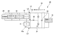
本実施の形態による電源装置10は、例えば図1〜図3に示すように、燃料電池スタック(FC)11と、バッテリ12と、第1DC−DCコンバータ13と、エアポンプインバータ14と、制御装置25とを備えて構成されている。そして、電源装置10は、例えば駆動モータインバータ15に接続されている。
Hereinafter, a power supply device and a power supply system for a fuel cell vehicle according to embodiments of the present invention will be described with reference to the accompanying drawings.
As shown in FIGS. 1 to 3, for example, the power supply device 10 according to the present embodiment includes a fuel cell stack (FC) 11, a battery 12, a first DC-DC converter 13, an air pump inverter 14, and a control device 25. And is configured. And the power supply device 10 is connected to the drive motor inverter 15, for example.

電源装置10は、例えば燃料電池車両の電源システム20に具備され、この燃料電池車両の電源システム20は、例えば図2および図3に示すように、電源装置10と、エアポンプ(AP)21と、駆動モータ22と、第2DC−DCコンバータ23と、空調機器24と、地絡センサ26と、出力電流センサ27と、相電流センサ28と、角度センサ29とを備えて構成されている。   The power supply device 10 is provided, for example, in a power supply system 20 of a fuel cell vehicle. The power supply system 20 of the fuel cell vehicle includes, for example, as shown in FIGS. 2 and 3, a power supply device 10, an air pump (AP) 21, The drive motor 22, the second DC-DC converter 23, the air conditioner 24, the ground fault sensor 26, the output current sensor 27, the phase current sensor 28, and the angle sensor 29 are configured.

燃料電池スタック11は、陽イオン交換膜等からなる固体高分子電解質膜を、アノード触媒およびガス拡散層からなる燃料極(アノード)と、カソード触媒およびガス拡散層からなる酸素極(カソード)とで挟持してなる電解質電極構造体を、更に一対のセパレータで挟持してなる燃料電池セルを多数組積層して構成され、燃料電池セルの積層体は一対のエンドプレートによって積層方向の両側から挟み込まれている。   The fuel cell stack 11 includes a solid polymer electrolyte membrane composed of a cation exchange membrane or the like, with a fuel electrode (anode) composed of an anode catalyst and a gas diffusion layer, and an oxygen electrode (cathode) composed of a cathode catalyst and a gas diffusion layer. The electrolyte electrode structure is sandwiched between a plurality of fuel battery cells that are sandwiched between a pair of separators. The fuel cell stack is sandwiched between a pair of end plates from both sides in the stacking direction. ing.

燃料電池スタック11のカソードには酸素を含む酸化剤ガス(反応ガス)である空気がエアポンプ21から供給され、アノードには水素を含む燃料ガス(反応ガス)が、例えば高圧の水素タンク(図示略)から供給されている。
そして、アノードのアノード触媒上で触媒反応によりイオン化された水素は、適度に加湿された固体高分子電解質膜を介してカソードへと移動し、この移動に伴って発生する電子が外部回路に取り出され、直流の電気エネルギーとして利用される。このときカソードにおいては、水素イオン、電子及び酸素が反応して水が生成される。
Air, which is an oxidant gas (reactive gas) containing oxygen, is supplied from the air pump 21 to the cathode of the fuel cell stack 11, and a fuel gas (reactive gas) containing hydrogen is supplied to the anode, for example, a high-pressure hydrogen tank (not shown). ).
Then, hydrogen ionized by the catalytic reaction on the anode catalyst of the anode moves to the cathode through the moderately humidified solid polymer electrolyte membrane, and electrons generated by this movement are taken out to an external circuit. It is used as direct current electric energy. At this time, at the cathode, hydrogen ions, electrons and oxygen react to produce water.

なお、エアポンプ21は、例えば車両の外部から空気を取り込んで圧縮し、この空気を反応ガスとして燃料電池スタック11のカソードに供給する。このエアポンプ21を駆動するモータ(図示略)の回転数は、制御装置25から出力される制御指令に基づき、例えばパルス幅変調(PWM)によるPWMインバータなどからなるエアポンプインバータ14により制御されている。   The air pump 21 takes in air from the outside of the vehicle, for example, compresses it, and supplies this air as a reaction gas to the cathode of the fuel cell stack 11. The rotational speed of a motor (not shown) for driving the air pump 21 is controlled by an air pump inverter 14 including, for example, a PWM inverter by pulse width modulation (PWM) based on a control command output from the control device 25.

なお、電源装置10ではバッテリ12の代わりに蓄電装置として、例えば電気二重層コンデンサや電解コンデンサなどからなるキャパシタを備えてもよい。   Note that the power supply device 10 may include a capacitor made of, for example, an electric double layer capacitor or an electrolytic capacitor as a power storage device instead of the battery 12.

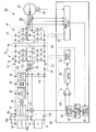
第1DC−DCコンバータ13は、例えばチョッパ型のDC−DCコンバータであって、図3に示すように、複数のスイッチング素子(例えば、IGBT:Insulated Gate Bipolar mode Transistor)がブリッジ接続されてなる3相のブリッジ回路31と、3相のチョークコイル32と、平滑コンデンサ33とを備えて構成されている。
なお、第1DC−DCコンバータ13を簡略化して示す図1および図2においては、3相のうち1相分のみのスイッチング素子とチョークコイル32のみを図示している。
The first DC-DC converter 13 is, for example, a chopper type DC-DC converter, and has a three-phase structure in which a plurality of switching elements (for example, IGBT: Insulated Gate Bipolar Mode Transistor) are bridge-connected as shown in FIG. The bridge circuit 31, the three-phase choke coil 32, and the smoothing capacitor 33 are provided.
In FIG. 1 and FIG. 2 showing the first DC-DC converter 13 in a simplified manner, only the switching element and choke coil 32 for only one phase among the three phases are shown.

ブリッジ回路31は、後述する3相の駆動モータインバータ15を構成する3相のブリッジ回路51と同等であって、例えば各相毎に対をなすハイ側およびロー側第1トランジスタAH,ALと、ハイ側およびロー側第2トランジスタBH,BLと、ハイ側およびロー側第3トランジスタCH,CLとがブリッジ接続されている。そして、各トランジスタAH,BH,CHはコレクタが2次側正極端子P2に接続されてハイサイドアームを構成し、各トランジスタAL,BL,CLはエミッタが2次側負極端子N2に接続されてローサイドアームを構成している。そして、各相毎に、ハイサイドアームの各トランジスタAH,BH,CHのエミッタはローサイドアームの各トランジスタAL,BL,CLのコレクタに接続され、各トランジスタAH,AL,BH,BL,CH,CLのコレクタ−エミッタ間には、エミッタからコレクタに向けて順方向となるようにして、各ダイオードDAH,DAL,DBH,DBL,DCH,DCLが接続されている。   The bridge circuit 31 is equivalent to a three-phase bridge circuit 51 that constitutes a three-phase drive motor inverter 15 described later. For example, the high-side and low-side first transistors AH and AL that form a pair for each phase, The high-side and low-side second transistors BH, BL and the high-side and low-side third transistors CH, CL are bridge-connected. Each transistor AH, BH, CH has a collector connected to the secondary side positive terminal P2 to form a high side arm, and each transistor AL, BL, CL has an emitter connected to the secondary side negative terminal N2 and has a low side. It constitutes an arm. For each phase, the emitters of the transistors AH, BH, and CH of the high-side arm are connected to the collectors of the transistors AL, BL, and CL of the low-side arm, and the transistors AH, AL, BH, BL, CH, and CL are connected. The diodes DAH, DAL, DBH, DBL, DCH, and DCL are connected between the collector and the emitter so as to be in the forward direction from the emitter to the collector.

そして、このブリッジ回路31は、制御装置25から出力されて各トランジスタのゲートに入力されるパルス幅変調(PWM)された信号(PWM信号)によって駆動され、ハイサイドアームの各トランジスタAH,BH,CHがオンかつローサイドアームの各トランジスタAL,BL,CLがオフとなる状態と、ハイサイドアームの各トランジスタAH,BH,CHがオフかつローサイドアームの各トランジスタAL,BL,CLがオンとなる状態とが、交互に切り替えられる。   The bridge circuit 31 is driven by a pulse width modulated (PWM) signal (PWM signal) output from the control device 25 and input to the gate of each transistor, and each of the transistors AH, BH, The state where CH is on and the transistors AL, BL, CL of the low side arm are off, and the state where the transistors AH, BH, CH of the high side arm are off and the transistors AL, BL, CL of the low side arm are on And are switched alternately.

平滑コンデンサ33は、2次側正極端子P2および2次側負極端子N2に接続されている。
3相のチョークコイル32は、各チョークコイル32の一端がブリッジ回路31の各相毎のコレクタ−エミッタ間、つまり各トランジスタAH,ALのコレクタ−エミッタ間および各トランジスタBH,BLのコレクタ−エミッタ間および各トランジスタCH,CLのコレクタ−エミッタ間のそれぞれに接続され、各チョークコイル32の他端は互いに1次側正極端子P1に接続されている。
The smoothing capacitor 33 is connected to the secondary side positive terminal P2 and the secondary side negative terminal N2.
In the three-phase choke coil 32, one end of each choke coil 32 is between the collector and emitter for each phase of the bridge circuit 31, that is, between the collector and emitter of each transistor AH and AL and between the collector and emitter of each transistor BH and BL. The other ends of the respective choke coils 32 are connected to the primary positive terminal P1.

3相のチョークコイル32は、例えば図4に示すように、単一の矩形のコア41にコモンモード巻きで巻回され、通電時に各チョークコイル32から発生する磁束の方向が同方向となるように設定されている。
そして、3相のうち何れか1相のチョークコイル32は、矩形のコア41をなす2対の対辺のうち一方の1対の対辺41aに分散して巻回され、3相のうち他の2相のチョークコイル32は、矩形のコア41をなす2対の対辺のうち他方の1対の対辺41bにぞれぞれ集中して巻回されている。
なお、3相の各チョークコイル32は、例えば図5に示すように、矩形のコア41をなす4辺のうち何れか3辺にぞれぞれ集中して巻回されてもよいし、他の巻線構造であってもよい。
For example, as shown in FIG. 4, the three-phase choke coil 32 is wound around a single rectangular core 41 by common mode winding so that the direction of magnetic flux generated from each choke coil 32 when energized is the same direction. Is set to
One of the three phases of the choke coil 32 is distributed and wound around one pair of opposite sides 41a of the two pairs of opposite sides forming the rectangular core 41, and the other two of the three phases. The phase choke coil 32 is concentratedly wound around the other pair of opposite sides 41 b of the two pairs of opposite sides forming the rectangular core 41.
For example, as shown in FIG. 5, each of the three-phase choke coils 32 may be wound in a concentrated manner on any three sides of the four sides forming the rectangular core 41. The winding structure may be used.

第1DC−DCコンバータ13は、例えば図3に示すように、電位の異なる3つの各ラインL1,L2,L3(例えば、L1の電位>L2の電位>L3の電位)に対して、1次側が第2ラインL2と第3ラインL3とに接続され、2次側が第1ラインL1と第3ラインL3とに接続されている。つまり、第1ラインL1は2次側正極端子P2に接続され、第2ラインL2は1次側正極端子P1に接続され、第3ラインL3は1次側負極端子N1および2次側負極端子N2に接続されている。   For example, as shown in FIG. 3, the first DC-DC converter 13 has a primary side with respect to three lines L1, L2, and L3 having different potentials (for example, potential of L1> potential of L2> potential of L3). The second side L2 and the third line L3 are connected, and the secondary side is connected to the first line L1 and the third line L3. That is, the first line L1 is connected to the secondary positive terminal P2, the second line L2 is connected to the primary positive terminal P1, and the third line L3 is the primary negative terminal N1 and the secondary negative terminal N2. It is connected to the.

この第1DC−DCコンバータ13は、例えば駆動モータ22の駆動時などにおける1次側から2次側への昇圧動作時には、先ず、ハイサイドアームの各トランジスタAH,BH,CHがオフかつローサイドアームの各トランジスタAL,BL,CLがオンとされ、1次側から入力される電流によってチョークコイル32が直流励磁されて磁気エネルギーが蓄積される。
そして、ハイサイドアームの各トランジスタAH,BH,CHがオンかつローサイドアームの各トランジスタAL,BL,CLがオフとされ、チョークコイル32に流れる電流が遮断されることに起因する磁束の変化を妨げるようにしてチョークコイル32の両端間に起電圧(誘導電圧)が発生し、チョークコイル32に蓄積された磁気エネルギーによる誘導電圧が1次側の入力電圧に上積みされて1次側の入力電圧よりも高い昇圧電圧が2次側に印加される。この切換動作に伴って発生する電圧変動は平滑コンデンサ33により平滑化され、昇圧電圧が2次側から出力される。
In the first DC-DC converter 13, for example, during the boosting operation from the primary side to the secondary side during driving of the drive motor 22, first, the transistors AH, BH, CH of the high side arm are turned off and the low side arm is turned off. The transistors AL, BL, and CL are turned on, and the choke coil 32 is DC-excited by the current input from the primary side to accumulate magnetic energy.
Then, the transistors AH, BH, and CH of the high-side arm are turned on and the transistors AL, BL, and CL of the low-side arm are turned off to prevent a change in magnetic flux caused by blocking the current flowing through the choke coil 32. In this way, an electromotive voltage (inductive voltage) is generated between both ends of the choke coil 32, and the induced voltage due to the magnetic energy accumulated in the choke coil 32 is added to the primary side input voltage so that the primary side input voltage is greater than the primary side input voltage. Higher boosted voltage is applied to the secondary side. The voltage fluctuation generated by this switching operation is smoothed by the smoothing capacitor 33, and the boosted voltage is output from the secondary side.

一方、例えば駆動モータ22の回生時などにおける2次側から1次側への回生動作時には、先ず、ハイサイドアームの各トランジスタAH,BH,CHがオフかつローサイドアームの各トランジスタAL,BL,CLがオンとされ、2次側から入力される電流によってチョークコイル32が直流励磁されて磁気エネルギーが蓄積される。
そして、ハイサイドアームの各トランジスタAH,BH,CHがオンかつローサイドアームの各トランジスタAL,BL,CLがオフとされ、チョークコイル32に流れる電流が遮断されることに起因する磁束の変化を妨げるようにしてチョークコイル32の両端間に起電圧(誘導電圧)が発生する。このチョークコイル32に蓄積された磁気エネルギーによる誘導電圧は、ハイサイドアームの各トランジスタAH,BH,CHのオン/オフの比率に応じて2次側の入力電圧が降圧された降圧電圧となり、降圧電圧が1次側に印加される。
On the other hand, at the time of regeneration operation from the secondary side to the primary side, for example, when the drive motor 22 is regenerating, first, the transistors AH, BH, CH of the high side arm are turned off and the transistors AL, BL, CL of the low side arm are first turned off. Is turned on, and the choke coil 32 is DC-excited by the current input from the secondary side to accumulate magnetic energy.
Then, the transistors AH, BH, and CH of the high-side arm are turned on and the transistors AL, BL, and CL of the low-side arm are turned off to prevent a change in magnetic flux caused by blocking the current flowing through the choke coil 32. Thus, an electromotive voltage (inductive voltage) is generated between both ends of the choke coil 32. The induced voltage generated by the magnetic energy accumulated in the choke coil 32 becomes a step-down voltage obtained by stepping down the input voltage on the secondary side according to the ON / OFF ratio of the transistors AH, BH, and CH of the high side arm. A voltage is applied to the primary side.

第1DC−DCコンバータ13は、制御装置25から出力されて各トランジスタのゲートに入力されるパルス幅変調(PWM)された信号(PWM信号)によって駆動され、例えばPWM信号の1周期におけるハイサイドアームの各トランジスタAH,BH,CHのオンの比率として定義されるスイッチングデューティーに応じて、ハイサイドアームの各トランジスタAH,BH,CHとローサイドアームの各トランジスタAL,BL,CLとのオン/オフを切り換える。
なお、ハイサイドアームの各トランジスタAH,BH,CHと、ローサイドアームの各トランジスタAL,BL,CLとは、オン/オフの切り換え時に、同時にオンとなることが禁止され、同時にオフとなる適宜のデッドタイムが設けられている。
The first DC-DC converter 13 is driven by a pulse width modulated (PWM) signal (PWM signal) output from the control device 25 and input to the gate of each transistor. For example, the high side arm in one cycle of the PWM signal The transistors AH, BH, CH of the high side arm and the transistors AL, BL, CL of the low side arm are turned on / off according to the switching duty defined as the ON ratio of the transistors AH, BH, CH. Switch.
It should be noted that the transistors AH, BH, and CH of the high side arm and the transistors AL, BL, and CL of the low side arm are prohibited from being turned on at the same time when being turned on / off, and appropriately turned off at the same time. Dead time is provided.

そして、燃料電池スタック11は正極側および負極側に配置されたコンタクタ11aとコンデンサ11bとを介して第2ラインL2と第3ラインL3とに接続され、バッテリ12は正極側および負極側に配置されたコンタクタ12aおよび正極側に配置された電流制限回路12bを介して第1ラインL1と第2ラインL2とに接続されている。これにより、第1ラインL1と第3ラインL3との間で燃料電池スタック11とバッテリ12とは直列に接続されて電池回路10aを形成している。
そして、第1ラインL1および第3ラインL3から負荷(例えば、駆動モータ22など)に電力が出力されるようにして第1ラインL1と第3ラインL3とは駆動モータインバータ15に接続されている。
The fuel cell stack 11 is connected to the second line L2 and the third line L3 via the contactor 11a and the capacitor 11b arranged on the positive electrode side and the negative electrode side, and the battery 12 is arranged on the positive electrode side and the negative electrode side. The contactor 12a is connected to the first line L1 and the second line L2 via the current limiting circuit 12b arranged on the positive electrode side. Thus, the fuel cell stack 11 and the battery 12 are connected in series between the first line L1 and the third line L3 to form a battery circuit 10a.
The first line L1 and the third line L3 are connected to the drive motor inverter 15 so that electric power is output from the first line L1 and the third line L3 to a load (for example, the drive motor 22). .

そして、エアポンプ21の駆動回路であるエアポンプインバータ14は第1ラインL1と第2ラインL2とに接続されている。   And the air pump inverter 14 which is a drive circuit of the air pump 21 is connected to the 1st line L1 and the 2nd line L2.

3相の駆動モータ22の駆動回路をなす駆動モータインバータ15は、例えばパルス幅変調(PWM)によるPWMインバータであって、複数のスイッチング素子(例えば、IGBT:Insulated Gate Bipolar mode Transistor)がブリッジ接続されてなる3相のブリッジ回路51を備えて構成されている。   The drive motor inverter 15 forming the drive circuit of the three-phase drive motor 22 is, for example, a PWM inverter by pulse width modulation (PWM), and a plurality of switching elements (for example, IGBT: Insulated Gate Bipolar mode Transistor) are bridge-connected. The three-phase bridge circuit 51 is configured.

ブリッジ回路51は、第1DC−DCコンバータ13を構成する3相のブリッジ回路31と同等であって、例えば各相毎に対をなすハイ側およびロー側U相トランジスタUH,ULと、ハイ側およびロー側V相トランジスタVH,VLと、ハイ側およびロー側W相トランジスタWH,WLとがブリッジ接続されている。そして、各トランジスタUH,VH,WHはコレクタが第1DC−DCコンバータ13の2次側正極端子P2に接続されてハイサイドアームを構成し、各トランジスタUL,VL,WLはエミッタが第1DC−DCコンバータ13の2次側負極端子N2に接続されてローサイドアームを構成している。そして、各相毎に、ハイサイドアームの各トランジスタUH,VH,WHのエミッタはローサイドアームの各トランジスタUL,VL,WLのコレクタに接続され、各トランジスタUH,UL,VH,VL,WH,WLのコレクタ−エミッタ間には、エミッタからコレクタに向けて順方向となるようにして、各ダイオードDUH,DUL,DVH,DVL,DWH,DWLが接続されている。   The bridge circuit 51 is equivalent to the three-phase bridge circuit 31 that constitutes the first DC-DC converter 13, and includes, for example, a high-side and low-side U-phase transistor UH, UL that forms a pair for each phase, Low-side V-phase transistors VH and VL and high-side and low-side W-phase transistors WH and WL are bridge-connected. The collectors of the transistors UH, VH, and WH are connected to the secondary side positive terminal P2 of the first DC-DC converter 13 to form a high side arm, and the emitters of the transistors UL, VL, and WL are the first DC-DC. A low side arm is configured by being connected to the secondary negative terminal N2 of the converter 13. For each phase, the emitters of the transistors UH, VH, WH of the high side arm are connected to the collectors of the transistors UL, VL, WL of the low side arm, and the transistors UH, UL, VH, VL, WH, WL. The diodes DUH, DUL, DVH, DVL, DWH, and DWL are connected between the collectors and the emitters so as to be forward from the emitter to the collector.

この駆動モータインバータ15は、制御装置25から出力されてブリッジ回路51の各トランジスタのゲートに入力されるパルス幅変調(PWM)された信号(PWM信号)によって駆動され、例えば駆動モータ22の駆動時には、各相毎に対をなす各トランジスタのオン(導通)/オフ(遮断)状態を切り替えることによって、電源装置10から出力される直流電力を3相交流電力に変換し、3相のステータ巻線への通電を順次転流させることで、各相のステータ巻線に交流のU相電流IuおよびV相電流IvおよびW相電流Iwを通電する。一方、例えば駆動モータ22の回生時には、駆動モータ22から出力される3相交流電力を直流電力に変換して第1DC−DCコンバータ13に供給し、バッテリ12の充電および第1DC−DCコンバータ13に接続された負荷に対する給電などをおこなう。
なお、駆動モータ22は、例えば界磁として永久磁石を利用する永久磁石式の3相交流同期モータとされており、駆動モータインバータ15から供給される3相交流電力により駆動制御されると共に、車両の減速時において駆動輪側から駆動モータ22側に駆動力が伝達されると、駆動モータ22は発電機として機能して、いわゆる回生制動力を発生し、車体の運動エネルギーを電気エネルギーとして回収する。
The drive motor inverter 15 is driven by a pulse width modulated (PWM) signal (PWM signal) output from the control device 25 and input to the gate of each transistor of the bridge circuit 51, for example, when driving the drive motor 22. The DC power output from the power supply apparatus 10 is converted into three-phase AC power by switching the on (conductive) / off (cut-off) state of each transistor paired for each phase, and the three-phase stator winding By sequentially commutating the energization to each other, AC U-phase current Iu, V-phase current Iv and W-phase current Iw are energized in the stator windings of each phase. On the other hand, for example, at the time of regeneration of the drive motor 22, the three-phase AC power output from the drive motor 22 is converted into DC power and supplied to the first DC-DC converter 13, and charging of the battery 12 and the first DC-DC converter 13 are performed. Supply power to the connected load.
The drive motor 22 is, for example, a permanent magnet type three-phase AC synchronous motor that uses a permanent magnet as a field, and is driven and controlled by the three-phase AC power supplied from the drive motor inverter 15. When the driving force is transmitted from the driving wheel side to the driving motor 22 side during deceleration, the driving motor 22 functions as a generator, generates a so-called regenerative braking force, and recovers the kinetic energy of the vehicle body as electric energy. .

第2DC−DCコンバータ23は、例えばチョッパ型のDC−DCコンバータであって、燃料電池車両に搭載される車両用補機の少なくとも一部(例えば、処理装置と、電磁バルブと、12V系負荷となど)が負荷として接続されている。
第2DC−DCコンバータ23は、第1ラインL1と第2ラインL2とに接続され、制御装置25から出力される制御指令に応じたチョッピング動作により、第1ラインL1と第2ラインL2との間に印加される電圧を降圧して、第2DC−DCコンバータ23に接続された負荷に供給する。
The second DC-DC converter 23 is, for example, a chopper type DC-DC converter, and is at least a part of a vehicle auxiliary machine mounted on the fuel cell vehicle (for example, a processing device, an electromagnetic valve, and a 12V system load). Etc.) as a load.
The second DC-DC converter 23 is connected to the first line L1 and the second line L2, and is connected between the first line L1 and the second line L2 by a chopping operation according to a control command output from the control device 25. Is stepped down and supplied to a load connected to the second DC-DC converter 23.

また、燃料電池車両に搭載される車両用補機の少なくとも一部をなす空調機器24は、例えば燃料電池車両に搭載されるヒータと、コンプレッサー用のモータおよび駆動回路(例えば、インバータなど)となどを備えて構成されている。
空調機器24は、第1ラインL1と第2ラインL2とに接続され、第1ラインL1および第2ラインL2から電力が供給される。
The air conditioner 24 that forms at least a part of the vehicular auxiliary machine mounted on the fuel cell vehicle includes, for example, a heater mounted on the fuel cell vehicle, a motor for a compressor, a drive circuit (for example, an inverter), and the like. It is configured with.
The air conditioner 24 is connected to the first line L1 and the second line L2, and power is supplied from the first line L1 and the second line L2.

制御装置25は、第1DC−DCコンバータ13のスイッチングデューティーを制御するデューティー制御をおこなうとともに、駆動モータインバータ15の電力変換動作を制御する。
制御装置25には、例えば、第1ラインL1と第3ラインL3とに接続されて地絡の発生を検知する地絡センサ26と、燃料電池スタック11の出力電流IFCを検出する出力電流センサ27と、駆動モータインバータ15と駆動モータ22との間において3相の各相電流を検出する相電流センサ28と、駆動モータ22の回転子の回転角(つまり、所定の基準回転位置からの回転子の磁極の回転角度であって、駆動モータ22の回転軸の回転位置)を検出する角度センサ29との各センサから出力される検出信号が入力されている。
The control device 25 performs duty control for controlling the switching duty of the first DC-DC converter 13 and controls the power conversion operation of the drive motor inverter 15.
The control device 25 includes, for example, a ground fault sensor 26 that is connected to the first line L1 and the third line L3 and detects the occurrence of a ground fault, and an output current sensor 27 that detects the output current IFC of the fuel cell stack 11. A phase current sensor 28 that detects currents of the three phases between the drive motor inverter 15 and the drive motor 22, and a rotation angle of the rotor of the drive motor 22 (that is, a rotor from a predetermined reference rotation position). A detection signal output from each of the sensors with an angle sensor 29 that detects the rotation angle of the magnetic pole of the drive motor 22 and the rotation position of the rotation shaft of the drive motor 22 is input.

制御装置25は、例えば、消費電力算出部61と、目標電力配分設定部62と、目標電流設定部63と、デューティー制御部64と、駆動モータ制御部65とを備えて構成されている。   The control device 25 includes, for example, a power consumption calculation unit 61, a target power distribution setting unit 62, a target current setting unit 63, a duty control unit 64, and a drive motor control unit 65.

消費電力算出部61は、電源装置10から電力が供給される負荷(例えば、電源装置10の外部の負荷である駆動モータ22および空調機器24および車両用補機など、および、電源装置10の内部の負荷であるエアポンプインバータ14など)の総消費電力を算出する。   The power consumption calculation unit 61 is a load to which power is supplied from the power supply device 10 (for example, a drive motor 22 and an air conditioner 24 that are loads external to the power supply device 10, a vehicular auxiliary machine, etc. The total power consumption of the air pump inverter 14, etc., which is the load of the

目標電力配分設定部62は、例えば駆動モータ22の駆動時においては、燃料電池スタック11の状態(例えば、発電指令に応じた燃料電池スタック11の状態変化の変化率など)と、バッテリ12の残容量SOCとなどに基づき、電源装置10の電池回路10aを形成する燃料電池スタック11とバッテリ12との電力配分、つまり消費電力算出部61により算出された総消費電力を燃料電池スタック11から出力される電力とバッテリ12から出力される電力とを加算して得た値とする際の配分を設定する。
例えば駆動モータ22の駆動時における電力配分は、第1DC−DCコンバータ13のスイッチングデューティー(つまり、PWM信号の1周期におけるハイサイドアームの各トランジスタAH,BH,CHのオンの比率)に応じた値となり、スイッチングデューティー(duty)は燃料電池スタック11の電圧(VFC)とバッテリ12の電圧(VB)とにより以下に示すように記述される。
For example, when the drive motor 22 is driven, the target power distribution setting unit 62 determines the state of the fuel cell stack 11 (for example, the rate of change in the state of the fuel cell stack 11 according to the power generation command) and the remaining battery 12. Based on the capacity SOC and the like, the power distribution between the fuel cell stack 11 and the battery 12 forming the battery circuit 10a of the power supply device 10, that is, the total power consumption calculated by the power consumption calculation unit 61 is output from the fuel cell stack 11. Distribution for setting the value obtained by adding the electric power to be output and the electric power output from the battery 12 is set.
For example, the power distribution at the time of driving the drive motor 22 is a value corresponding to the switching duty of the first DC-DC converter 13 (that is, the ON ratio of the transistors AH, BH, and CH of the high-side arm in one cycle of the PWM signal). The switching duty (duty) is described by the voltage (VFC) of the fuel cell stack 11 and the voltage (VB) of the battery 12 as shown below.

duty=VFC/(VFC+VB) duty = VFC / (VFC + VB)

これにより、以下に示すようにスイッチングデューティー(duty)によって燃料電池スタック11の電圧(VFC)とバッテリ12の電圧(VB)との比が記述される。   Thereby, the ratio between the voltage (VFC) of the fuel cell stack 11 and the voltage (VB) of the battery 12 is described by the switching duty (duty) as shown below.

VB/VFC=(1−duty)/duty VB / VFC = (1-duty) / duty

燃料電池スタック11の電圧(VFC)とバッテリ12の電圧(VB)とは、例えば図6および図7に示すように、それぞれ燃料電池スタック11の電流(出力電流Ifc)および電力とバッテリ12の電流(Ib)および電力と所定の対応関係を有することから、スイッチングデューティー(duty)により、燃料電池スタック11の動作点(例えば、電圧または電流または電力)とバッテリ12の動作点(例えば、電圧または電流または電力)との比が記述される。   The voltage (VFC) of the fuel cell stack 11 and the voltage (VB) of the battery 12 are, for example, as shown in FIGS. 6 and 7, the current (output current Ifc) and power of the fuel cell stack 11 and the current of the battery 12, respectively. (Ib) and power have a predetermined correspondence relationship, and therefore, the operating point (for example, voltage or current or power) of the fuel cell stack 11 and the operating point of the battery 12 (for example, voltage or current) are set according to the switching duty. Or the ratio of power).

また、目標電力配分設定部62は、例えば駆動モータ22の回生時においては、燃料電池スタック11の状態(例えば、発電指令に応じた燃料電池スタック11の状態変化の変化率など)と、バッテリ12の残容量SOCと、駆動モータ22の回生電力となどに基づき、燃料電池スタック11と駆動モータインバータ15との電力供給側の電力配分、および、バッテリ12と負荷(例えば、空調機器24および車両用補機およびエアポンプインバータ14など)との電力受給側の電力配分を設定する。   Further, the target power distribution setting unit 62, for example, at the time of regeneration of the drive motor 22, the state of the fuel cell stack 11 (for example, the rate of change in the state of the fuel cell stack 11 according to the power generation command), the battery 12 and the like. Power distribution on the power supply side of the fuel cell stack 11 and the drive motor inverter 15, and the battery 12 and the load (for example, for the air conditioner 24 and the vehicle) based on the remaining capacity SOC of the motor and the regenerative power of the drive motor 22 Power distribution on the power receiving side with the auxiliary machine and the air pump inverter 14) is set.

目標電流設定部63は、例えば駆動モータ22の駆動時においては、スイッチングデューティー(duty)により、燃料電池スタック11の動作点(例えば、電圧または電流または電力)とバッテリ12の動作点(例えば、電圧または電流または電力)との比が記述されることから、燃料電池スタック11の動作点とバッテリ12の動作点と第1DC−DCコンバータ13のスイッチングデューティーと負荷の総消費電力との対応関係を示す所定マップを参照して、燃料電池スタック11の出力電流Ifcに対する目標電流を取得する。   For example, when the drive motor 22 is driven, the target current setting unit 63 determines the operating point (for example, voltage, current, or power) of the fuel cell stack 11 and the operating point (for example, voltage) of the fuel cell stack 11 according to the switching duty (duty). (Or current or electric power) ratio is described, the corresponding relationship among the operating point of the fuel cell stack 11, the operating point of the battery 12, the switching duty of the first DC-DC converter 13, and the total power consumption of the load is shown. With reference to the predetermined map, a target current for the output current Ifc of the fuel cell stack 11 is acquired.

この所定マップは、例えば図8に示すように、燃料電池スタック11の動作点とバッテリ12の動作点とを直交座標とする2次元座標上において、第1DC−DCコンバータ13のスイッチングデューティーの複数の値毎に対して設定された燃料電池スタック11の動作点とバッテリ12の動作点との対応関係(D(1),…,D(k),…)と、負荷の総消費電力の複数の値毎に対して設定された燃料電池スタック11の動作点とバッテリ12の動作点との対応関係(P(1),…,P(k),…)とを備えている。
そして、第1DC−DCコンバータ13のスイッチングデューティーの複数の値毎に対して設定された対応関係では、スイッチングデューティーに応じた比率で燃料電池スタック11の動作点の増大に伴いバッテリ12の動作点が増大傾向に変化するように設定されている。
また、負荷の総消費電力の複数の値毎に対して設定された燃料電池スタック11の動作点とバッテリ12の動作点との対応関係では、燃料電池スタック11の動作点に応じた電力とバッテリ12の動作点に応じた電力との和が負荷の総消費電力と等しくなるような動作点の組み合わせが設定されている。
For example, as shown in FIG. 8, the predetermined map has a plurality of switching duties of the first DC-DC converter 13 on a two-dimensional coordinate having the operating point of the fuel cell stack 11 and the operating point of the battery 12 as orthogonal coordinates. A correspondence relationship (D (1),..., D (k),...) Between the operating point of the fuel cell stack 11 and the operating point of the battery 12 set for each value, and a plurality of total power consumption of the load A correspondence relationship (P (1),..., P (k),...) Between the operating point of the fuel cell stack 11 and the operating point of the battery 12 set for each value is provided.
In the correspondence relationship set for each of the plurality of values of the switching duty of the first DC-DC converter 13, the operating point of the battery 12 increases as the operating point of the fuel cell stack 11 increases at a ratio corresponding to the switching duty. It is set to change in an increasing trend.
Further, in the correspondence relationship between the operating point of the fuel cell stack 11 and the operating point of the battery 12 set for each of a plurality of values of the total power consumption of the load, the power and the battery corresponding to the operating point of the fuel cell stack 11 A combination of operating points is set such that the sum of the power corresponding to the 12 operating points is equal to the total power consumption of the load.

目標電流設定部63は、燃料電池スタック11の動作点とバッテリ12の動作点とを直交座標とする2次元座標上において、消費電力算出部61により算出された負荷の総消費電力に応じた対応関係P(k)と目標電力配分設定部62により設定された電力配分に応じた第1DC−DCコンバータ13のスイッチングデューティーに応じた対応関係D(k)との交点を燃料電池スタック11およびバッテリ12の動作点とし、この動作点に応じた燃料電池スタック11の電流(出力電流Ifc)を目標電流として出力する。   The target current setting unit 63 corresponds to the total power consumption of the load calculated by the power consumption calculation unit 61 on a two-dimensional coordinate in which the operation point of the fuel cell stack 11 and the operation point of the battery 12 are orthogonal coordinates. The intersection of the relationship P (k) and the corresponding relationship D (k) corresponding to the switching duty of the first DC-DC converter 13 corresponding to the power distribution set by the target power distribution setting unit 62 is the fuel cell stack 11 and the battery 12. And the current (output current Ifc) of the fuel cell stack 11 corresponding to this operating point is output as a target current.

また、目標電流設定部63は、例えば駆動モータ22の回生時においては、目標電力配分設定部62により設定された電力配分に応じて、燃料電池スタック11の電流(出力電流Ifc)の目標電流として零あるいは正の値を出力する。   For example, when the drive motor 22 is regenerated, the target current setting unit 63 sets the target current of the fuel cell stack 11 (output current Ifc) according to the power distribution set by the target power distribution setting unit 62. Output zero or positive value.

デューティー制御部64は、燃料電池スタック11とバッテリ12との実際の電力配分(実電力配分)が目標電力配分設定部62により設定された電力配分(目標電力配分)に一致するようにして、例えば出力電流センサ27から出力される燃料電池スタック11の出力電流IFCの検出値が目標電流設定部63から出力される燃料電池スタック11の電流(出力電流Ifc)の目標電流に一致するようにして、第1DC−DCコンバータ13のスイッチングデューティーを制御する。
デューティー制御部64は、例えば、電流偏差算出部71と、フィードバック処理部72と、PWM信号生成部73とを備えて構成されている。
The duty control unit 64 is configured so that the actual power distribution (actual power distribution) between the fuel cell stack 11 and the battery 12 matches the power distribution (target power distribution) set by the target power distribution setting unit 62, for example. The detected value of the output current IFC of the fuel cell stack 11 output from the output current sensor 27 matches the target current of the current (output current Ifc) of the fuel cell stack 11 output from the target current setting unit 63, The switching duty of the first DC-DC converter 13 is controlled.
The duty control unit 64 includes, for example, a current deviation calculation unit 71, a feedback processing unit 72, and a PWM signal generation unit 73.

電流偏差算出部71は、出力電流センサ27から出力される燃料電池スタック11の出力電流IFCの検出値と、目標電流設定部63から出力される燃料電池スタック11の電流(出力電流Ifc)の目標電流との電流偏差を算出して出力する。
フィードバック処理部72は、例えばPID(比例積分微分)動作により、電流偏差算出部71から出力される電流偏差を制御増幅して電圧指令値を算出する。
The current deviation calculating unit 71 detects the output value IFC of the fuel cell stack 11 output from the output current sensor 27 and the target of the current (output current Ifc) of the fuel cell stack 11 output from the target current setting unit 63. Calculate and output the current deviation from the current.
The feedback processing unit 72 calculates a voltage command value by controlling and amplifying the current deviation output from the current deviation calculating unit 71 by, for example, a PID (proportional integral derivative) operation.

PWM信号生成部73は、フィードバック処理部72から出力される電圧指令値に応じた出力電流Ifcを燃料電池スタック11から出力するために、第1DC−DCコンバータ13のハイサイドアームの各トランジスタAH,BH,CHおよびローサイドアームの各トランジスタAL,BL,CLをオン/オフ駆動させるゲート信号(つまり、PWM信号)を生成して出力する。   The PWM signal generation unit 73 outputs the output current Ifc in accordance with the voltage command value output from the feedback processing unit 72 from the fuel cell stack 11, so that each transistor AH of the high side arm of the first DC-DC converter 13. A gate signal (that is, a PWM signal) for driving on / off the transistors AL, BL, and CL of the BH and CH and the low-side arm is generated and output.

駆動モータ制御部65は、例えば駆動モータ22の駆動時においては、回転直交座標をなすdq座標上で電流のフィードバック制御(ベクトル制御)をおこなうものであり、運転者のアクセル操作および駆動モータ22の回転数などに基づくトルク指令に応じた目標d軸電流及び目標q軸電流を演算し、目標d軸電流及び目標q軸電流に基づいて3相の各相出力電圧Vu,Vv,Vwを算出し、各相出力電圧Vu,Vv,Vwに応じて駆動モータインバータ15のブリッジ回路51へゲート信号であるPWM信号を入力すると共に、実際にF駆動モータインバータ15から駆動モータ22に供給される各相電流Iu,Iv,Iwの検出値をdq座標上に変換して得たd軸電流及びq軸電流と、目標d軸電流及び目標q軸電流との各偏差がゼロとなるように制御をおこなう。   For example, when the drive motor 22 is driven, the drive motor control unit 65 performs feedback control (vector control) of current on the dq coordinates forming the rotation orthogonal coordinates, and the driver's accelerator operation and the drive motor 22 are controlled. The target d-axis current and the target q-axis current are calculated according to the torque command based on the rotational speed and the like, and the three-phase output voltages Vu, Vv, Vw are calculated based on the target d-axis current and the target q-axis current. The PWM signal as the gate signal is input to the bridge circuit 51 of the drive motor inverter 15 according to the phase output voltages Vu, Vv, Vw, and each phase supplied to the drive motor 22 from the F drive motor inverter 15 is actually supplied. Each deviation between the d-axis current and the q-axis current obtained by converting the detected values of the currents Iu, Iv, and Iw onto the dq coordinate and the target d-axis current and the target q-axis current is zero. So as to perform control.

また、駆動モータ制御部65は、例えば駆動モータ22の回生時においては、角度センサ29から出力される駆動モータ22の回転子の回転角θmの出力波形に基づいて同期がとられたパルスに応じて駆動モータインバータ15のブリッジ回路51の各トランジスタをオン/オフ駆動させ、駆動モータ制御部65から出力される3相交流電力を直流電力に変換する。このとき、駆動モータ制御部65は、ブリッジ回路51の各トランジスタをオン/オフ駆動させるゲート信号のデューティーに応じた回生電圧のフィードバック制御をおこない、所定の電圧値を駆動モータインバータ15の1次側つまり第1DC−DCコンバータ13の2次側正極端子P2と2次側負極端子N2との間に出力する。   Further, the drive motor control unit 65 responds to a pulse synchronized based on the output waveform of the rotation angle θm of the rotor of the drive motor 22 output from the angle sensor 29, for example, during regeneration of the drive motor 22. Then, the transistors of the bridge circuit 51 of the drive motor inverter 15 are turned on / off to convert the three-phase AC power output from the drive motor control unit 65 into DC power. At this time, the drive motor control unit 65 performs feedback control of the regenerative voltage in accordance with the duty of the gate signal that drives each transistor of the bridge circuit 51 on / off, and sets the predetermined voltage value to the primary side of the drive motor inverter 15. That is, the signal is output between the secondary positive terminal P2 and the secondary negative terminal N2 of the first DC-DC converter 13.

つまり、制御装置25は、例えば駆動モータ22の駆動時においては、燃料電池スタック11の電流(出力電流Ifc)の検出値が目標電流と一致するようにしてフィードバック制御をおこなうことによって、第1DC−DCコンバータ13のスイッチングデューティーを制御することにより、例えば図9に示すように、電源装置10の動作モードを連続的に制御する。   That is, for example, when the drive motor 22 is driven, the control device 25 performs the feedback control so that the detected value of the current (output current Ifc) of the fuel cell stack 11 matches the target current, whereby the first DC− By controlling the switching duty of the DC converter 13, for example, as shown in FIG. 9, the operation mode of the power supply device 10 is continuously controlled.

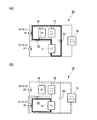
例えば第1DC−DCコンバータ13の昇圧比が2〜3程度の値となる状態で、スイッチングデューティーが最大となる電源装置10の動作モードは、例えば図10(A),(B)に示すように、バッテリ12の出力のみが駆動モータインバータ15およびエアポンプインバータ14に供給されるEVモードとなる。   For example, in the state where the step-up ratio of the first DC-DC converter 13 is a value of about 2 to 3, the operation mode of the power supply device 10 with the maximum switching duty is, for example, as shown in FIGS. 10 (A) and 10 (B). Only the output of the battery 12 is in the EV mode supplied to the drive motor inverter 15 and the air pump inverter 14.

そして、EVモードからスイッチングデューティーが低下傾向に変化することに伴い、電源装置10の動作モードは、例えば図11(A),(B)〜図13(A),(B)に示すように、順次、バッテリ12の出力が駆動モータインバータ15およびエアポンプインバータ14に供給されると共に燃料電池スタック11の出力が駆動モータインバータ15に供給されてバッテリ12の電流(Ib)が燃料電池スタック11の電流(出力電流Ifc)よりも大きくなる第1の(FC+バッテリ)モードと、バッテリ12の出力が駆動モータインバータ15およびエアポンプインバータ14に供給されると共に燃料電池スタック11の出力が駆動モータインバータ15に供給されてバッテリ12の電流(Ib)が燃料電池スタック11の電流(出力電流Ifc)とエアポンプインバータ14に通電される電流(IAP)との和に等しくなる第2の(FC+バッテリ)モードと、バッテリ12および燃料電池スタック11の出力が駆動モータインバータ15およびエアポンプインバータ14に供給されてバッテリ12の電流(Ib)が燃料電池スタック11の電流(出力電流Ifc)よりも小さくなる第3の(FC+バッテリ)モードとに推移する。
これに伴い、例えば図9に示すように、バッテリ12の電流(Ib)が減少傾向に変化し、燃料電池スタック11の電流(出力電流Ifc)及び目標電流(Ifcコマンド)は増大傾向に変化する。そして、駆動モータインバータ15の1次側の入力電圧(VPIN)はほぼ一定に維持されつつ、バッテリ12の電圧(VB)は増大傾向に変化し、燃料電池スタック11の電圧(VFC)は減少傾向に変化する。
As the switching duty changes from the EV mode to a decreasing tendency, the operation mode of the power supply device 10 is, for example, as shown in FIGS. 11 (A), (B) to 13 (A), (B). The output of the battery 12 is sequentially supplied to the drive motor inverter 15 and the air pump inverter 14 and the output of the fuel cell stack 11 is supplied to the drive motor inverter 15 so that the current (Ib) of the battery 12 is the current of the fuel cell stack 11 ( In the first (FC + battery) mode in which the output current Ifc) is greater, the output of the battery 12 is supplied to the drive motor inverter 15 and the air pump inverter 14, and the output of the fuel cell stack 11 is supplied to the drive motor inverter 15. The current (Ib) of the battery 12 Current (Ifc) and the second (FC + battery) mode equal to the sum of the current (IAP) energized to the air pump inverter 14 and the outputs of the battery 12 and the fuel cell stack 11 to the drive motor inverter 15 and the air pump inverter 14. When the current (Ib) of the battery 12 is supplied and the current (output current Ifc) of the fuel cell stack 11 becomes smaller, the mode changes to the third (FC + battery) mode.
Accordingly, for example, as shown in FIG. 9, the current (Ib) of the battery 12 changes to a decreasing tendency, and the current (output current Ifc) and the target current (Ifc command) of the fuel cell stack 11 change to an increasing tendency. . Then, the primary input voltage (VPIN) of the drive motor inverter 15 is maintained substantially constant, the voltage (VB) of the battery 12 changes to increase, and the voltage (VFC) of the fuel cell stack 11 decreases. To change.

そして、第3の(FC+バッテリ)モードからスイッチングデューティーが最小まで低下傾向に変化することに伴い、電源装置10の動作モードは、例えば図14(A),(B)〜図15(A),(B)に示すように、順次、燃料電池スタック11の出力のみが駆動モータインバータ15およびエアポンプインバータ14に供給される第1のFCモードと、燃料電池スタック11の出力のみが駆動モータインバータ15およびエアポンプインバータ14およびバッテリ12に供給されてバッテリ12が充電される第2のFCモードとに推移する。
これに伴い、例えば図9に示すように、バッテリ12の電流(Ib)が零から負の値へと減少傾向に変化し、燃料電池スタック11の電流(出力電流Ifc)及び目標電流(Ifcコマンド)は増大傾向に変化する。そして、駆動モータインバータ15の1次側の入力電圧(VPIN)はほぼ一定に維持されつつ、バッテリ12の電圧(VB)は増大傾向に変化し、燃料電池スタック11の電圧(VFC)は減少傾向に変化する。
As the switching duty changes from the third (FC + battery) mode to the minimum, the operation mode of the power supply device 10 is, for example, FIG. 14 (A), (B) to FIG. 15 (A), As shown in (B), in order, only the output of the fuel cell stack 11 is supplied to the drive motor inverter 15 and the air pump inverter 14, and only the output of the fuel cell stack 11 is the drive motor inverter 15 and A transition is made to the second FC mode in which the battery 12 is charged by being supplied to the air pump inverter 14 and the battery 12.
Accordingly, as shown in FIG. 9, for example, the current (Ib) of the battery 12 changes from zero to a negative value, and the current (output current Ifc) and the target current (Ifc command) of the fuel cell stack 11 change. ) Changes to an increasing trend. Then, the primary input voltage (VPIN) of the drive motor inverter 15 is maintained substantially constant, the voltage (VB) of the battery 12 changes to increase, and the voltage (VFC) of the fuel cell stack 11 decreases. To change.

また、制御装置25は、例えば駆動モータ22の回生時においては、燃料電池スタック11の電流(出力電流Ifc)の検出値が目標電流(零あるいは正の値)と一致するようにしてフィードバック制御をおこなうとともに、回生電圧のフィードバック制御をおこなうことによって、第1DC−DCコンバータ13のスイッチングデューティーを制御する。
例えば燃料電池スタック11の電流(出力電流Ifc)の目標電流が零とされる電源装置10の動作モードは、例えば図16(A),(B)に示すように、駆動モータインバータ15の回生電力によりバッテリ12が充電される回生モードとなる。
また、例えば燃料電池スタック11の電流(出力電流Ifc)の目標電流が正の値とされる電源装置10の動作モードは、例えば図17(A),(B)に示すように、駆動モータインバータ15の回生電力および燃料電池スタック11の出力がエアポンプインバータ14およびバッテリ12に供給されてバッテリ12が充電される(回生+FCによるバッテリ充電)モードとなる。
For example, when the drive motor 22 is regenerating, the control device 25 performs feedback control so that the detected value of the current (output current Ifc) of the fuel cell stack 11 matches the target current (zero or positive value). In addition, the switching duty of the first DC-DC converter 13 is controlled by performing feedback control of the regenerative voltage.
For example, the operation mode of the power supply apparatus 10 in which the target current of the current (output current Ifc) of the fuel cell stack 11 is zero is, for example, as shown in FIGS. 16A and 16B, the regenerative power of the drive motor inverter 15. Thus, the regeneration mode in which the battery 12 is charged is set.
Further, for example, the operation mode of the power supply device 10 in which the target current of the current (output current Ifc) of the fuel cell stack 11 is set to a positive value is a drive motor inverter as shown in FIGS. The regenerative power of 15 and the output of the fuel cell stack 11 are supplied to the air pump inverter 14 and the battery 12, and the battery 12 is charged (battery charging by regeneration + FC).

なお、制御装置25は、例えば、燃料電池車両の運転状態や、燃料電池スタック11のアノードに供給される反応ガスに含まれる水素の濃度や、燃料電池スタック11のアノードから排出される排出ガスに含まれる水素の濃度や、燃料電池スタック11の発電状態、例えば各複数の燃料電池セルの端子間電圧や、燃料電池スタック11の電圧VFCや、燃料電池スタック11の出力電流Ifcや、燃料電池スタック11の内部温度などに基づき、燃料電池スタック11に対する発電指令として、燃料電池スタック11へ供給される反応ガスの圧力および流量に対する指令値を出力し、燃料電池スタック11の発電状態を制御する。   For example, the control device 25 determines the operating state of the fuel cell vehicle, the concentration of hydrogen contained in the reaction gas supplied to the anode of the fuel cell stack 11, and the exhaust gas discharged from the anode of the fuel cell stack 11. The concentration of hydrogen contained, the power generation state of the fuel cell stack 11, for example, the voltage between terminals of each of the plurality of fuel cells, the voltage VFC of the fuel cell stack 11, the output current Ifc of the fuel cell stack 11, and the fuel cell stack 11, a command value for the pressure and flow rate of the reaction gas supplied to the fuel cell stack 11 is output as a power generation command for the fuel cell stack 11 based on the internal temperature of the fuel cell stack 11, and the power generation state of the fuel cell stack 11 is controlled.

また、制御装置25は、燃料電池スタック11の発電状態などに応じてコンタクタ11aのオン/オフを切り換え、燃料電池スタック11と第2ラインL2および第3ラインL3との接続を制御する。
また、制御装置25は、バッテリ12の残容量SOCなどに応じてコンタクタ12aおよび電流制限回路12bのオン/オフを切り換え、バッテリ12と第1ラインL1および第2ラインL2との接続を制御する。
Further, the control device 25 switches on / off of the contactor 11a according to the power generation state of the fuel cell stack 11 and controls the connection between the fuel cell stack 11 and the second line L2 and the third line L3.
Further, the control device 25 switches on / off of the contactor 12a and the current limiting circuit 12b in accordance with the remaining capacity SOC of the battery 12, and controls the connection between the battery 12 and the first line L1 and the second line L2.

本発明の実施形態による電源装置10および燃料電池車両の電源システム20は上記構成を備えており、次に、電源装置10および燃料電池車両の電源システム20の動作、特に、燃料電池スタック11の電流(出力電流Ifc)の検出値が目標電流に一致するようにしてフィードバック制御をおこなうことによって、第1DC−DCコンバータ13のスイッチングデューティーを制御する動作について添付図面を参照しながら説明する。   The power supply device 10 and the fuel cell vehicle power supply system 20 according to the embodiment of the present invention have the above-described configuration. Next, the operation of the power supply device 10 and the fuel cell vehicle power supply system 20, particularly the current of the fuel cell stack 11. The operation of controlling the switching duty of the first DC-DC converter 13 by performing feedback control so that the detected value of (output current Ifc) matches the target current will be described with reference to the accompanying drawings.

先ず、例えば図18に示すステップS01においては、電源装置10から電力が供給される負荷(例えば、駆動モータ22および空調機器24および車両用補機など)の総消費電力を算出する。
次に、ステップS02においては、燃料電池スタック11の状態(例えば、発電指令に応じた燃料電池スタック11の状態変化の変化率など)と、バッテリ12の残容量SOCとなどに基づき、電源装置10の電池回路10aを形成する燃料電池スタック11とバッテリ12との電力配分、つまり負荷の総消費電力を燃料電池スタック11から出力される電力とバッテリ12から出力される電力とを加算して得た値とする際の配分を設定する。なお、この電力配分は第1DC−DCコンバータ13のスイッチングデューティーに応じた値となる。
First, for example, in step S01 shown in FIG. 18, the total power consumption of a load (for example, the drive motor 22, the air conditioner 24, the vehicular auxiliary machine, etc.) supplied with power from the power supply device 10 is calculated.
Next, in step S02, the power supply apparatus 10 is based on the state of the fuel cell stack 11 (for example, the rate of change in the state of the fuel cell stack 11 according to the power generation command), the remaining capacity SOC of the battery 12, and the like. Power distribution between the fuel cell stack 11 and the battery 12 forming the battery circuit 10a of the battery, that is, the total power consumption of the load was obtained by adding the power output from the fuel cell stack 11 and the power output from the battery 12 Set the distribution when making the value. This power distribution is a value corresponding to the switching duty of the first DC-DC converter 13.

次に、ステップS03においては、例えば駆動モータ22の駆動時においては、燃料電池スタック11の動作点とバッテリ12の動作点と第1DC−DCコンバータ13のスイッチングデューティーと負荷の総消費電力との対応関係を示す所定マップを参照して、燃料電池スタック11の出力電流Ifcに対する目標電流を取得する。   Next, in step S03, for example, when the drive motor 22 is driven, the correspondence between the operating point of the fuel cell stack 11, the operating point of the battery 12, the switching duty of the first DC-DC converter 13, and the total power consumption of the load. The target current for the output current Ifc of the fuel cell stack 11 is acquired with reference to a predetermined map indicating the relationship.

次に、ステップS04においては、出力電流センサ27から出力される燃料電池スタック11の出力電流IFCの検出値を取得する。
次に、ステップS05においては、出力電流センサ27から出力される燃料電池スタック11の出力電流IFCの検出値と目標電流との電流偏差を、例えばPID(比例積分微分)動作などにより制御増幅して電圧指令値を算出する。
Next, in step S04, the detected value of the output current IFC of the fuel cell stack 11 output from the output current sensor 27 is acquired.
Next, in step S05, the current deviation between the detected value of the output current IFC of the fuel cell stack 11 output from the output current sensor 27 and the target current is controlled and amplified by, for example, a PID (proportional integral derivative) operation. Calculate the voltage command value.

次に、ステップS06においては、電圧指令値に応じた出力電流Ifcを燃料電池スタック11から出力するために、第1DC−DCコンバータ13のハイサイドアームの各トランジスタAH,BH,CHおよびローサイドアームの各トランジスタAL,BL,CLをオン/オフ駆動させるゲート信号(つまり、PWM信号)を生成する。   Next, in step S06, in order to output the output current Ifc according to the voltage command value from the fuel cell stack 11, the transistors AH, BH, CH of the high side arm of the first DC-DC converter 13 and the low side arm of the low side arm are output. A gate signal (that is, a PWM signal) that drives each of the transistors AL, BL, and CL on / off is generated.

次に、ステップS07においては、PWM信号に応じて第1DC−DCコンバータ13のハイサイドアームの各トランジスタAH,BH,CHおよびローサイドアームの各トランジスタAL,BL,CLをオン/オフ駆動し、リターンに進む。   Next, in step S07, the transistors AH, BH, CH of the high side arm and the transistors AL, BL, CL of the low side arm of the first DC-DC converter 13 are turned on / off according to the PWM signal, and the return Proceed to

上述したように、本発明の実施形態による電源装置10によれば、燃料電池スタック11とバッテリ12とが直列に接続されてなる電池回路10aに対して単一の第1DC−DCコンバータ13を備え、負荷の総消費電力に対する燃料電池スタック11とバッテリ12との実電力配分が目標電力配分に一致するようにして第1DC−DCコンバータ13のスイッチングデューティーを制御することによって、燃料電池スタック11とバッテリ12との電力の応じた複数の動作モードを任意に切り換えることができ、例えば燃料電池スタック11とバッテリ12毎に個別にDC−DCコンバータを備える場合に比べて、構成に要する費用を削減すると共にサイズを小型化しつつ、適切な電力供給制御をおこなうことができる。   As described above, according to the power supply device 10 according to the embodiment of the present invention, the single first DC-DC converter 13 is provided for the battery circuit 10a in which the fuel cell stack 11 and the battery 12 are connected in series. By controlling the switching duty of the first DC-DC converter 13 so that the actual power distribution between the fuel cell stack 11 and the battery 12 with respect to the total power consumption of the load matches the target power distribution, the fuel cell stack 11 and the battery A plurality of operation modes can be arbitrarily switched according to the power with respect to 12, for example, compared with the case where a DC-DC converter is individually provided for each of the fuel cell stack 11 and the battery 12, and the cost required for the configuration is reduced. Appropriate power supply control can be performed while reducing the size.

さらに、本発明の実施形態による燃料電池車両の電源システム20によれば、単一の第1DC−DCコンバータ13のみを備えることで電源装置10の構成に要する費用を削減すると共にサイズを小型化することができることに加えて、燃料電池スタック11とバッテリ12とが直列に接続されることから、例えば燃料電池スタック11とバッテリ12とが並列に接続される場合に比べて、駆動モータインバータ15の動作電圧を増大させ、かつ、電流を低下させることができ、駆動モータ22および駆動モータインバータ15のサイズを小型化することができると共に運転効率を向上させることができ、燃料電池車両の電源システム20の構成に要する費用を削減すると共にサイズを小型化しつつ、適切な電力供給制御をおこなうことができる。
また、第1DC−DCコンバータ13の異常時(例えば、開放故障時など)であっても、電池回路10aから駆動モータインバータ15に電源を供給することができ、燃料電池車両を走行させることができる。
Furthermore, according to the power supply system 20 of the fuel cell vehicle according to the embodiment of the present invention, by providing only the single first DC-DC converter 13, the cost required for the configuration of the power supply device 10 is reduced and the size is reduced. Since the fuel cell stack 11 and the battery 12 are connected in series, the operation of the drive motor inverter 15 can be performed as compared with the case where the fuel cell stack 11 and the battery 12 are connected in parallel. The voltage can be increased and the current can be reduced, the size of the drive motor 22 and the drive motor inverter 15 can be reduced, and the driving efficiency can be improved, and the power supply system 20 of the fuel cell vehicle can be improved. It is possible to perform appropriate power supply control while reducing the cost of configuration and reducing the size. That.
Further, even when the first DC-DC converter 13 is abnormal (for example, when an open failure occurs), power can be supplied from the battery circuit 10a to the drive motor inverter 15, and the fuel cell vehicle can be driven. .

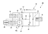
なお、上述した実施の形態においては、燃料電池車両に搭載される車両用補機の少なくとも一部(例えば、第2DC−DCコンバータ23とは独立した空調機器24など、および、第2DC−DCコンバータ23に接続される負荷(処理装置と、電磁バルブと、12V系負荷となど))は、直接あるいは第2DC−DCコンバータ23を介して、第1ラインL1と第2ラインL2とに接続されるとしたが、これに限定されず、例えば図19に示すように、第2ラインL2と第3ラインL3とに接続されてもよいし、例えば図20に示すように、第1ラインL1と第3ラインL3とに接続されてもよい。   In the above-described embodiment, at least a part of the vehicular auxiliary equipment mounted on the fuel cell vehicle (for example, the air conditioner 24 independent of the second DC-DC converter 23, and the second DC-DC converter). A load (processing device, electromagnetic valve, 12V system load, etc.) connected to 23 is connected to the first line L1 and the second line L2 directly or via the second DC-DC converter 23. However, the present invention is not limited to this. For example, as shown in FIG. 19, the second line L2 and the third line L3 may be connected. For example, as shown in FIG. It may be connected to 3 lines L3.

なお、上述した実施の形態においては、エアポンプ21の駆動回路であるエアポンプインバータ14は第1ラインL1と第2ラインL2とに接続されているとしたが、これに限定されず、燃料電池スタック11に反応ガスを供給するポンプ(例えば、エアポンプ21など)および冷媒を供給するポンプ(図示略)のうち少なくとも1つのポンプの駆動回路が第1ラインL1と第2ラインL2とに接続されてもよい。
また、燃料電池スタック11に反応ガスを供給するポンプ(例えば、エアポンプ21など)および冷媒を供給するポンプ(図示略)のうち少なくとも1つのポンプの駆動回路が、第2ラインL2と第3ラインL3に接続されてもよいし、第1ラインL2と第3ラインL3に接続されてもよい。
In the above-described embodiment, the air pump inverter 14 that is the drive circuit of the air pump 21 is connected to the first line L1 and the second line L2. However, the present invention is not limited to this, and the fuel cell stack 11 A driving circuit for at least one of a pump (for example, an air pump 21) and a pump (not shown) for supplying a refrigerant to the reaction gas may be connected to the first line L1 and the second line L2. .
In addition, a drive circuit for at least one of a pump (for example, an air pump 21) that supplies a reaction gas to the fuel cell stack 11 and a pump (not shown) that supplies a refrigerant includes a second line L2 and a third line L3. May be connected to the first line L2 and the third line L3.

なお、上述した実施の形態においては、バッテリ12は第1ラインL1と第2ラインL2とに接続され、燃料電池スタック11は第2ラインL2と第3ラインL3とに接続されるとしたが、これに限定されず、燃料電池スタック11は第1ラインL1と第2ラインL2とに接続され、バッテリ12は第2ラインL2と第3ラインL3とに接続されてもよい。   In the above-described embodiment, the battery 12 is connected to the first line L1 and the second line L2, and the fuel cell stack 11 is connected to the second line L2 and the third line L3. The fuel cell stack 11 may be connected to the first line L1 and the second line L2, and the battery 12 may be connected to the second line L2 and the third line L3.

なお、上述した実施の形態においては、制御装置25は燃料電池スタック11とバッテリ12との実電力配分が目標電力配分に一致するようにして、例えば燃料電池スタック11の電流(出力電流Ifc)の検出値が目標電流に一致するようにしてフィードバック制御をおこなうことによって、第1DC−DCコンバータ13のスイッチングデューティーを制御するとしたが、これに限定されず、例えば燃料電池スタック11の電流(出力電流Ifc)の代わりに、バッテリ12の電流(Ib)が目標値に一致するようにしてフィードバック制御をおこなってもよい。また、電流の代わりに、燃料電池スタック11の電圧(VFC)またはバッテリ12の電圧(VB)の検出値が目標値に一致するようにしてフィードバック制御をおこなってもよいし、燃料電池スタック11とバッテリ12との出力比が目標値に一致するようにしてスイッチングデューティーをフィードバック制御してもよい。   In the embodiment described above, the control device 25 sets the actual power distribution between the fuel cell stack 11 and the battery 12 to match the target power distribution, for example, the current of the fuel cell stack 11 (output current Ifc). The switching duty of the first DC-DC converter 13 is controlled by performing feedback control so that the detected value matches the target current. However, the present invention is not limited to this. For example, the current (output current Ifc) ), Feedback control may be performed such that the current (Ib) of the battery 12 matches the target value. Further, instead of the current, feedback control may be performed so that the detected value of the voltage (VFC) of the fuel cell stack 11 or the voltage (VB) of the battery 12 matches the target value. The switching duty may be feedback controlled so that the output ratio with the battery 12 matches the target value.

なお、上述した実施の形態においては、第1DC−DCコンバータ13は、ハイサイドアームの各トランジスタAH,BH,CHがオフかつローサイドアームの各トランジスタAL,BL,CLがオンの状態と、ハイサイドアームの各トランジスタAH,BH,CHがオンかつローサイドアームの各トランジスタAL,BL,CLがオフの状態とを交互に切り換えるとしたが、これに限定されず、例えば駆動モータ22の駆動時などにおける1次側から2次側への昇圧動作時には、ハイサイドアームの各トランジスタAH,BH,CHがオフに維持された状態でローサイドアームの各トランジスタAL,BL,CLのオンとオフとを交互に切り換え、例えば駆動モータ22の回生時などにおける2次側から1次側への回生動作時には、ローサイドアームの各トランジスタAL,BL,CLがオフに維持された状態でハイサイドアームの各トランジスタAH,BH,CHのオンとオフとを交互に切り換えてもよい。   In the above-described embodiment, the first DC-DC converter 13 is configured such that the high side arm transistors AH, BH, and CH are off and the low side arm transistors AL, BL, and CL are on, Although the transistors AH, BH, and CH of the arm are turned on and the transistors AL, BL, and CL of the low-side arm are alternately switched off, the present invention is not limited to this. For example, when the drive motor 22 is driven. During the step-up operation from the primary side to the secondary side, the transistors AH, BH, and CH of the high-side arm are kept off and the transistors AL, BL, and CL of the low-side arm are alternately turned on and off. When switching, for example, during regeneration of the drive motor 22 from the secondary side to the primary side, Each transistor AL of Doamu, BL, CL is the transistors AH of the high-side arm while being kept off, BH, may be switched alternately with CH on and off.

本発明の実施形態に係る電源装置の構成図である。It is a block diagram of the power supply device which concerns on embodiment of this invention. 本発明の実施形態に係る燃料電池車両の電源システムの構成図である。It is a block diagram of the power supply system of the fuel cell vehicle which concerns on embodiment of this invention. 本発明の実施形態に係る燃料電池車両の電源システムの構成図である。It is a block diagram of the power supply system of the fuel cell vehicle which concerns on embodiment of this invention. 本発明の実施形態に係る3相のチョークコイルの構成図である。It is a block diagram of the three-phase choke coil which concerns on embodiment of this invention. 本発明の実施形態の第1変形例に係る3相のチョークコイルの構成図である。It is a block diagram of the three-phase choke coil which concerns on the 1st modification of embodiment of this invention. 本発明の実施形態に係る燃料電池スタックの動作点の一例を示す図である。It is a figure which shows an example of the operating point of the fuel cell stack which concerns on embodiment of this invention. 本発明の実施形態に係るバッテリの動作点の一例を示す図である。It is a figure which shows an example of the operating point of the battery which concerns on embodiment of this invention. 本発明の実施形態に係る燃料電池スタックの動作点とバッテリの動作点と第1DC−DCコンバータのスイッチングデューティーと負荷の総消費電力との対応関係を示す所定マップの一例を示す図である。It is a figure which shows an example of the predetermined map which shows the correspondence of the operating point of the fuel cell stack which concerns on embodiment of this invention, the operating point of a battery, the switching duty of a 1st DC-DC converter, and the total power consumption of load. 本発明の実施形態に係る駆動モータの駆動時における第1DC−DCコンバータのスイッチングデューティーの変化に応じた電源装置の動作モードの変化と燃料電池スタックおよびバッテリの電流および電圧の変化の一例とを示す図である。FIG. 7 shows a change in the operation mode of the power supply device according to a change in the switching duty of the first DC-DC converter and an example of changes in the current and voltage of the fuel cell stack and the battery when the drive motor according to the embodiment of the present invention is driven. FIG. 本発明の実施形態に係る駆動モータの駆動時における電源装置の動作モード(EVモード)での通電状態を示す図である。It is a figure which shows the electricity supply state in the operation mode (EV mode) of the power supply device at the time of the drive of the drive motor which concerns on embodiment of this invention. 本発明の実施形態に係る駆動モータの駆動時における電源装置の動作モード(第1の(FC+バッテリ)モード)での通電状態を示す図である。It is a figure which shows the energization state in the operation mode (1st (FC + battery) mode) of the power supply device at the time of the drive of the drive motor which concerns on embodiment of this invention. 本発明の実施形態に係る駆動モータの駆動時における電源装置の動作モード(第2の(FC+バッテリ)モード)での通電状態を示す図である。It is a figure which shows the energization state in the operation mode (2nd (FC + battery) mode) of the power supply device at the time of the drive of the drive motor which concerns on embodiment of this invention. 本発明の実施形態に係る駆動モータの駆動時における電源装置の動作モード(第3の(FC+バッテリ)モード)での通電状態を示す図である。It is a figure which shows the energization state in the operation mode (3rd (FC + battery) mode) of the power supply device at the time of the drive of the drive motor which concerns on embodiment of this invention. 本発明の実施形態に係る駆動モータの駆動時における電源装置の動作モード(第1のFCモード)での通電状態を示す図である。It is a figure which shows the energization state in the operation mode (1st FC mode) of the power supply device at the time of the drive of the drive motor which concerns on embodiment of this invention. 本発明の実施形態に係る駆動モータの駆動時における電源装置の動作モード(第2のFCモード)での通電状態を示す図である。It is a figure which shows the electricity supply state in the operation mode (2nd FC mode) of the power supply device at the time of the drive of the drive motor which concerns on embodiment of this invention. 本発明の実施形態に係る駆動モータの回生時における電源装置の動作モード(回生モード)での通電状態を示す図である。It is a figure which shows the electricity supply state in the operation mode (regeneration mode) of the power supply device at the time of regeneration of the drive motor which concerns on embodiment of this invention. 本発明の実施形態に係る駆動モータの回生時における電源装置の動作モード((回生+FCによるバッテリ充電)モード)での通電状態を示す図である。It is a figure which shows the energization state in the operation mode ((battery charge by regeneration + FC) mode) at the time of regeneration of the drive motor which concerns on embodiment of this invention. 本発明の実施形態に係る燃料電池車両の電源システムの動作を示すフローチャートである。It is a flowchart which shows operation | movement of the power supply system of the fuel cell vehicle which concerns on embodiment of this invention. 本発明の実施形態の第2変形例に係る燃料電池車両の電源システムの構成図である。It is a block diagram of the power supply system of the fuel cell vehicle which concerns on the 2nd modification of embodiment of this invention. 本発明の実施形態の第3変形例に係る燃料電池車両の電源システムの構成図である。It is a block diagram of the power supply system of the fuel cell vehicle which concerns on the 3rd modification of embodiment of this invention.

符号の説明Explanation of symbols

10 電源装置
10a 電池回路
11 燃料電池スタック
12 バッテリ(蓄電装置)
13 第1DC−DCコンバータ(DC−DCコンバータ)
14 エアポンプインバータ
15 駆動モータインバータ
20 燃料電池車両の電源システム
21 エアポンプ
22 駆動モータ(車両駆動用電動機)
23 第2DC−DCコンバータ
24 空調機器
25 制御装置
61 消費電力算出部(消費電力取得手段)
62 目標電力配分設定部(目標電力配分設定手段)
63 目標電流設定部(目標電流設定手段)
64 デューティー制御部(デューティー制御手段)
DESCRIPTION OF SYMBOLS 10 Power supply device 10a Battery circuit 11 Fuel cell stack 12 Battery (power storage device)
13 First DC-DC converter (DC-DC converter)
14 Air Pump Inverter 15 Drive Motor Inverter 20 Fuel Cell Vehicle Power Supply System 21 Air Pump 22 Drive Motor (Vehicle Drive Electric Motor)
23 2nd DC-DC converter 24 Air-conditioning equipment 25 Control apparatus 61 Power consumption calculation part (power consumption acquisition means)
62 Target power distribution setting unit (target power distribution setting means)
63 Target current setting section (target current setting means)
64 Duty control unit (Duty control means)

Claims (6)

電位の異なる第1ラインおよび第2ラインおよび第3ラインと、
燃料電池スタックと蓄電装置とが直列に接続されてなる電池回路と、
DC−DCコンバータとを備え、
前記電池回路の両端は前記第1ラインと前記第3ラインとに接続され、
前記電池回路の前記燃料電池スタックと前記蓄電装置との接続点は前記第2ラインに接続され、
前記DC−DCコンバータの1次側は前記第2ラインと前記第3ラインとに接続され、
前記DC−DCコンバータの2次側は前記第1ラインと前記第3ラインとに接続され、
前記第1ラインおよび前記第3ラインから負荷に電力を供給しており、
前記負荷の消費電力を取得する消費電力取得手段と、
前記消費電力に基づいて前記燃料電池スタックと前記蓄電装置との目標電力配分を設定する目標電力配分設定手段と、
前記燃料電池スタックと前記蓄電装置との実電力配分が前記目標電力配分に一致するようにして前記DC−DCコンバータのスイッチングデューティーを制御するデューティー制御手段と
を備えることを特徴とする電源装置。
A first line, a second line, and a third line having different potentials;
A battery circuit in which a fuel cell stack and a power storage device are connected in series;
A DC-DC converter,
Both ends of the battery circuit are connected to the first line and the third line,
A connection point between the fuel cell stack of the battery circuit and the power storage device is connected to the second line,
The primary side of the DC-DC converter is connected to the second line and the third line,
The secondary side of the DC-DC converter is connected to the first line and the third line,
Supplying power to the load from the first line and the third line;
Power consumption acquisition means for acquiring the power consumption of the load;
Target power distribution setting means for setting target power distribution between the fuel cell stack and the power storage device based on the power consumption;
A power supply apparatus comprising: duty control means for controlling a switching duty of the DC-DC converter so that an actual power distribution between the fuel cell stack and the power storage device matches the target power distribution.
前記消費電力取得手段は、前記電源装置の外部の負荷の外部負荷消費電力と前記電源装置の内部の負荷の内部負荷消費電力とを含む前記消費電力を取得することを特徴とする請求項1に記載の電源装置。 The said power consumption acquisition means acquires the said power consumption including the external load power consumption of the load outside the said power supply device, and the internal load power consumption of the load inside the said power supply device. The power supply described. 前記目標電力配分に基づき前記燃料電池スタックまたは前記蓄電装置の目標電流を設定する目標電流設定手段を備え、
前記デューティー制御手段は、前記燃料電池スタックまたは前記蓄電装置の実電流が前記目標電流に一致するようにして前記スイッチングデューティーをフィードバック制御することを特徴とする請求項1または請求項2に記載の電源装置。
A target current setting means for setting a target current of the fuel cell stack or the power storage device based on the target power distribution,
3. The power supply according to claim 1, wherein the duty control unit feedback-controls the switching duty so that an actual current of the fuel cell stack or the power storage device matches the target current. 4. apparatus.
前記目標電力配分に基づき前記燃料電池スタックまたは前記蓄電装置の目標電圧を設定する目標電圧設定手段を備え、
前記デューティー制御手段は、前記燃料電池スタックまたは前記蓄電装置の実電圧が前記目標電圧に一致するようにして前記スイッチングデューティーをフィードバック制御することを特徴とする請求項1または請求項2に記載の電源装置。
A target voltage setting means for setting a target voltage of the fuel cell stack or the power storage device based on the target power distribution;
3. The power supply according to claim 1, wherein the duty control unit feedback-controls the switching duty so that an actual voltage of the fuel cell stack or the power storage device matches the target voltage. 4. apparatus.
前記目標電力配分設定手段は前記目標電力配分として前記燃料電池スタックと前記蓄電装置との目標出力比を設定しており、
前記デューティー制御手段は、前記燃料電池スタックと前記蓄電装置との実出力比が前記目標出力比に一致するようにして前記スイッチングデューティーをフィードバック制御することを特徴とする請求項1または請求項2に記載の電源装置。
The target power distribution setting means sets a target output ratio between the fuel cell stack and the power storage device as the target power distribution,
The duty control means feedback-controls the switching duty so that an actual output ratio between the fuel cell stack and the power storage device matches the target output ratio. The power supply described.
請求項1から請求項5の何れか1つに記載の電源装置と、
前記電源装置から電力が供給される車両駆動用電動機と
を備えることを特徴とする燃料電池車両の電源システム。
The power supply device according to any one of claims 1 to 5,
A power supply system for a fuel cell vehicle, comprising: a vehicle drive motor to which electric power is supplied from the power supply device.
JP2008274306A 2008-10-24 2008-10-24 Power unit and power system for fuel cell vehicle Pending JP2010104168A (en)

Priority Applications (1)

Application Number Priority Date Filing Date Title
JP2008274306A JP2010104168A (en) 2008-10-24 2008-10-24 Power unit and power system for fuel cell vehicle

Applications Claiming Priority (1)

Application Number Priority Date Filing Date Title
JP2008274306A JP2010104168A (en) 2008-10-24 2008-10-24 Power unit and power system for fuel cell vehicle

Publications (2)

Publication Number Publication Date
JP2010104168A true JP2010104168A (en) 2010-05-06
JP2010104168A5 JP2010104168A5 (en) 2010-09-09

Family

ID=42294271

Family Applications (1)

Application Number Title Priority Date Filing Date
JP2008274306A Pending JP2010104168A (en) 2008-10-24 2008-10-24 Power unit and power system for fuel cell vehicle

Country Status (1)

Country Link
JP (1) JP2010104168A (en)

Cited By (4)

* Cited by examiner, † Cited by third party
Publication number Priority date Publication date Assignee Title
JP2011091884A (en) * 2009-10-20 2011-05-06 Honda Motor Co Ltd Power supply device
CN104617319A (en) * 2015-01-26 2015-05-13 西南交通大学 PEMFC pile current loading method
CN108859798A (en) * 2017-05-11 2018-11-23 现代自动车株式会社 Electricity generation system and electricity-generating method for fuel-cell vehicle
CN110867597A (en) * 2019-11-21 2020-03-06 电子科技大学 Thermoelectric water cooperative control method for consistency of proton exchange membrane fuel cell

Citations (4)

* Cited by examiner, † Cited by third party
Publication number Priority date Publication date Assignee Title
JP2002231287A (en) * 2001-01-26 2002-08-16 Equos Research Co Ltd Fuel cell device and its control method
WO2004066472A1 (en) * 2003-01-24 2004-08-05 Mitsubishi Denki Kabushiki Kaisha Battery power circuit
JP2008211952A (en) * 2007-02-28 2008-09-11 Matsushita Electric Ind Co Ltd Power supply unit
JP2010102992A (en) * 2008-10-24 2010-05-06 Honda Motor Co Ltd Power source system for fuel cell vehicle

Patent Citations (4)

* Cited by examiner, † Cited by third party
Publication number Priority date Publication date Assignee Title
JP2002231287A (en) * 2001-01-26 2002-08-16 Equos Research Co Ltd Fuel cell device and its control method
WO2004066472A1 (en) * 2003-01-24 2004-08-05 Mitsubishi Denki Kabushiki Kaisha Battery power circuit
JP2008211952A (en) * 2007-02-28 2008-09-11 Matsushita Electric Ind Co Ltd Power supply unit
JP2010102992A (en) * 2008-10-24 2010-05-06 Honda Motor Co Ltd Power source system for fuel cell vehicle

Cited By (6)

* Cited by examiner, † Cited by third party
Publication number Priority date Publication date Assignee Title
JP2011091884A (en) * 2009-10-20 2011-05-06 Honda Motor Co Ltd Power supply device
CN104617319A (en) * 2015-01-26 2015-05-13 西南交通大学 PEMFC pile current loading method
CN108859798A (en) * 2017-05-11 2018-11-23 现代自动车株式会社 Electricity generation system and electricity-generating method for fuel-cell vehicle
CN108859798B (en) * 2017-05-11 2023-06-30 现代自动车株式会社 Power generation system and power generation method for fuel cell vehicle
CN110867597A (en) * 2019-11-21 2020-03-06 电子科技大学 Thermoelectric water cooperative control method for consistency of proton exchange membrane fuel cell
CN110867597B (en) * 2019-11-21 2022-06-14 电子科技大学 Thermoelectric water cooperative control method for consistency of proton exchange membrane fuel cell

Similar Documents

Publication Publication Date Title
JP5352182B2 (en) Power supply device and power supply system for fuel cell vehicle
US7661494B2 (en) Power supply system of fuel cell vehicle
US8866331B2 (en) Power supply device and power supply system for fuel cell vehicle
US7946365B2 (en) Control method for fuel cell vehicle, and fuel cell vehicle
JP5264941B2 (en) Electric vehicle power supply
JP3842015B2 (en) Idle control device for fuel cell vehicle
US9236736B2 (en) Power supply system and method for controlling the same
JP5887077B2 (en) Power supply system and fuel cell vehicle
JP5380550B2 (en) Starting the power supply
JP4982576B2 (en) Fuel cell vehicle
JP5352185B2 (en) Power supply system for fuel cell vehicles
JP2010104168A (en) Power unit and power system for fuel cell vehicle
JP5352186B2 (en) Power supply device and power supply system for fuel cell vehicle
JP5352183B2 (en) Power supply device and power supply system for fuel cell vehicle
JP5286025B2 (en) Power supply device and power supply system for fuel cell vehicle
JP5352184B2 (en) Power supply device and power supply system for fuel cell vehicle
JP5322683B2 (en) Electric vehicle power supply system
JP5002639B2 (en) Power supply
JP5673354B2 (en) Fuel cell system
JP2010187450A (en) Power supply system for electric vehicle
JP2010187449A (en) Power supply system for electric vehicle
JP2014121186A (en) Fuel-cell vehicle

Legal Events

Date Code Title Description
A521 Written amendment

Free format text: JAPANESE INTERMEDIATE CODE: A523

Effective date: 20100727

A621 Written request for application examination

Free format text: JAPANESE INTERMEDIATE CODE: A621

Effective date: 20101125

A977 Report on retrieval

Free format text: JAPANESE INTERMEDIATE CODE: A971007

Effective date: 20120611

A131 Notification of reasons for refusal

Free format text: JAPANESE INTERMEDIATE CODE: A131

Effective date: 20120724

A02 Decision of refusal

Free format text: JAPANESE INTERMEDIATE CODE: A02

Effective date: 20130507