JP2010101902A - Nir clinical opti-scan system - Google Patents
Nir clinical opti-scan system Download PDFInfo
- Publication number
- JP2010101902A JP2010101902A JP2009288287A JP2009288287A JP2010101902A JP 2010101902 A JP2010101902 A JP 2010101902A JP 2009288287 A JP2009288287 A JP 2009288287A JP 2009288287 A JP2009288287 A JP 2009288287A JP 2010101902 A JP2010101902 A JP 2010101902A
- Authority
- JP
- Japan
- Prior art keywords
- fiber
- light
- tissue
- array
- fiber bundle
- Prior art date
- Legal status (The legal status is an assumption and is not a legal conclusion. Google has not performed a legal analysis and makes no representation as to the accuracy of the status listed.)
- Granted
Links
Images


Classifications
-
- G—PHYSICS
- G01—MEASURING; TESTING
- G01N—INVESTIGATING OR ANALYSING MATERIALS BY DETERMINING THEIR CHEMICAL OR PHYSICAL PROPERTIES
- G01N21/00—Investigating or analysing materials by the use of optical means, i.e. using sub-millimetre waves, infrared, visible or ultraviolet light
- G01N21/17—Systems in which incident light is modified in accordance with the properties of the material investigated
- G01N21/47—Scattering, i.e. diffuse reflection
- G01N21/4795—Scattering, i.e. diffuse reflection spatially resolved investigating of object in scattering medium
-
- A—HUMAN NECESSITIES
- A61—MEDICAL OR VETERINARY SCIENCE; HYGIENE
- A61B—DIAGNOSIS; SURGERY; IDENTIFICATION
- A61B5/00—Measuring for diagnostic purposes; Identification of persons
- A61B5/0059—Measuring for diagnostic purposes; Identification of persons using light, e.g. diagnosis by transillumination, diascopy, fluorescence
- A61B5/0073—Measuring for diagnostic purposes; Identification of persons using light, e.g. diagnosis by transillumination, diascopy, fluorescence by tomography, i.e. reconstruction of 3D images from 2D projections
Landscapes
- Health & Medical Sciences (AREA)
- Life Sciences & Earth Sciences (AREA)
- Physics & Mathematics (AREA)
- Pathology (AREA)
- General Health & Medical Sciences (AREA)
- Surgery (AREA)
- Veterinary Medicine (AREA)
- Engineering & Computer Science (AREA)
- Biomedical Technology (AREA)
- Heart & Thoracic Surgery (AREA)
- Medical Informatics (AREA)
- Molecular Biology (AREA)
- Radiology & Medical Imaging (AREA)
- Animal Behavior & Ethology (AREA)
- Nuclear Medicine, Radiotherapy & Molecular Imaging (AREA)
- Public Health (AREA)
- Biophysics (AREA)
- Optics & Photonics (AREA)
- Chemical & Material Sciences (AREA)
- Analytical Chemistry (AREA)
- Biochemistry (AREA)
- General Physics & Mathematics (AREA)
- Immunology (AREA)
- Investigating Or Analysing Materials By Optical Means (AREA)
- Mechanical Optical Scanning Systems (AREA)
- Length Measuring Devices By Optical Means (AREA)
- Analysing Materials By The Use Of Radiation (AREA)
Abstract
Description
発明の分野
本発明は三次元光学作像技術に関し、特に、人体組織の如き複雑で無秩序な媒体における吸収及び(又は)散乱構造の、媒体から出射する散乱光を検出することによる、検出及び三次元作像に関する。
FIELD OF THE INVENTION The present invention relates to three-dimensional optical imaging techniques, and in particular, detection and tertiary by detecting scattered light emanating from a medium of absorption and / or scattering structures in complex and disordered media such as human tissue. Concerning the original image.
人体の内部領域の三次元画像を提供できる大半の医療診断機器は著しく大型で高価である。磁気共振作像(MRI)機器に関連する空間要求及びコストは、しばしば、三次元画像が適正な診断にとって必要な場合でさえも、機器を実現不可能な診断オプションにしてしまう。従来のコンピュータ補助断層写真(CAT)走査装置は、大型で高価なほかに、潜在的に有害な放射線に患者を晒すことを付加的に要求する。 Most medical diagnostic equipment that can provide a three-dimensional image of an internal region of the human body is significantly larger and expensive. The space requirements and costs associated with magnetic resonance imaging (MRI) instruments often make the instrument an unfeasible diagnostic option even when three-dimensional images are necessary for proper diagnosis. In addition to being large and expensive, conventional computer-aided tomography (CAT) scanners additionally require exposing the patient to potentially harmful radiation.
人体組織の如き散乱媒体内に埋もれた物体を検出及び特定するための光学的方法は望ましい。その理由は、電磁スペクトルの有害部分からの放射の必要性をも排除しながら、光学装置を小型で、軽量で、比較的安価にできるからである。光学装置はまた、スペクトル分析を遂行することにより構造体の化学構造を決定することができ、これは、MRIやCAT作像装置からは利用できない能力である。 Optical methods for detecting and identifying objects buried in scattering media such as human tissue are desirable. The reason is that the optical device can be made smaller, lighter and relatively inexpensive while eliminating the need for radiation from harmful parts of the electromagnetic spectrum. The optical device can also determine the chemical structure of the structure by performing spectral analysis, a capability not available from MRI or CAT imagers.
医療応用に対する光学装置の1つの問題点は、人体が濃密な即ち散乱性の媒体であり、これが入射光を標的物体から離れる方向へ拡散させ、もって物体からの位置及び表面形態(topology)データを不明瞭にしてしまうことである。濃密な媒体内に埋もれた物体を作像するための好ましい光学診断具は埋もれた標的から反射された複散乱光信号から有用な情報を引き出すことのできるものでなければならない。 One problem with optical devices for medical applications is that the human body is a dense or scattering medium, which diffuses the incident light away from the target object, thus producing position and surface morphology data from the object. It is obscure. A preferred optical diagnostic tool for imaging an object buried in a dense medium must be able to extract useful information from the double scattered light signal reflected from the buried target.
「無秩序媒体を作像する方法」なる名称の米国特許第5,137,355号明細書(以下、「355号特許」という)は、人体組織内への顕著な侵入が生じる電磁スペクトルの近赤外(NIR)領域における散乱光の測定を基礎とする非侵入的な医療作像技術を開示している。前述の技術の前は、濃密な媒体内の標的の光学的な検出について多くの試みがなされたが、埋もれた物体の深さ及び構造を作像する問題が依然として残った。上記355号特許の技術は、観察者が三次元画像を正確に検出し、濃密な媒体内に位置する標的物体を分光学的に特徴づけることを可能にした。 US Pat. No. 5,137,355 (hereinafter referred to as “355 patent”) entitled “Method of Imaging Disordered Media” is a near-red region of the electromagnetic spectrum that causes significant penetration into human tissue. A non-invasive medical imaging technique based on the measurement of scattered light in the outside (NIR) region is disclosed. Prior to the foregoing techniques, many attempts were made to optically detect targets in dense media, but the problem of imaging the depth and structure of buried objects remained. The technology of the above-mentioned 355 patent allows an observer to accurately detect a three-dimensional image and to spectroscopically characterize a target object located in a dense medium.
355号特許に開示された技術は多重波長視準(collimated)源と視準レシーバとを使用し、入射光線の各位置に対して試片からの散乱光の位置的及び角度的な走査を遂行する。この技術は濃密な媒体内での物体の深さ、構造並びに吸収及び散乱特性の決定を可能にする。 The technique disclosed in the '355 patent uses a multi-wavelength collimated source and a collimating receiver to perform a positional and angular scan of the scattered light from the specimen for each position of the incident beam. To do. This technique allows the determination of the depth, structure and absorption and scattering properties of an object in a dense medium.
355号特許で述べられた方法論は高散乱性媒体の内部構造の像をいかにして再現するかに関する基本的な説明を提示する。必要なことは、すべての伝搬が粒子画(即ち、放射搬送式)に従って正確に描くように、検出信号に十分な散乱を受けさせることである。従って、この方法論は、伝播信号の時間的な特徴の査定に関して、任意の型式のエネルギ源(例えば、電磁、音響粒子ビーム)及び任意の源条件(例えば、DC、時間分解又はAC)を含む。この方法論は一般表現においては正しいが、特に非理想的な条件下で測定をいかに最良に行うかに関して特別な詳細を述べていない。 The methodology described in the '355 patent provides a basic explanation on how to reproduce an image of the internal structure of a highly scattering medium. All that is required is that the detection signal be sufficiently scattered so that all propagation is accurately drawn according to the particle image (ie, radiation transport). Thus, this methodology includes any type of energy source (eg, electromagnetic, acoustic particle beam) and any source condition (eg, DC, time resolved or AC) for assessing the temporal characteristics of the propagated signal. Although this methodology is correct in general terms, it does not give any particular details on how best to make measurements, especially under non-ideal conditions.
例えば、高質画像の構築のための好ましい要求は、患者からの呼吸や心臓の鼓動により生じる不可避の運動から由来する運動部分(motion artifact) の如きこのような非理想的な要素を排除することである。 For example, a preferred requirement for the construction of high quality images is to eliminate such non-ideal elements such as motion artifacts derived from inevitable movements caused by patient breathing and heartbeats. It is.
本発明は、運動部分を最小にした不均一試片形状を作像する改善された光学作像装置及び技術に関する。 The present invention relates to an improved optical imaging apparatus and technique for imaging a non-uniform specimen shape with minimal moving parts.
本発明に係る不均一表面形状を有する組織構造を光学断層写真式に作像するための装置は、組織を通して少なくとも減衰伝送を行うことのできる波長を有する光を提供できる光源と;光源から作像すべき組織へ光を伝送するためのファイバ束を含むファイバアレイと、組織により散乱された光を受け取るファイバ束を含む第2のファイバアレイと;各ファイバ束の一端を支持する調整可能な支持部材を含む調整可能な組立体であって、ファイバ束が多数の離間した地点で作像された組織の表面内へ光を伝送し表面から出射する光を収集するように、作像されている試片の表面に適合する各支持部材の部分に沿って分布しているような組立体と;第2のファイバ束内のファイバにより収集された光を受け取る検出アレイと;を有する。 An apparatus for optically tomographically imaging a tissue structure having a non-uniform surface shape according to the present invention comprises: a light source capable of providing light having a wavelength capable of at least attenuated transmission through the tissue; A fiber array that includes fiber bundles for transmitting light to the tissue to be treated; a second fiber array that includes fiber bundles that receive light scattered by the tissue; and an adjustable support member that supports one end of each fiber bundle. An adjustable assembly comprising: a fiber bundle, wherein the fiber bundle is imaged to transmit light into and collect light exiting the imaged tissue surface at a number of spaced points. An assembly that is distributed along the portion of each support member that conforms to the surface of the strip; and a detection array that receives light collected by the fibers in the second fiber bundle.
ダイオードレーザー、Ti:サフィアレーザー、ダイレーザー、多重波長レーザー、連続波(CW)レーザー及びパルスパワーレーザーを含むいくつかの光源を装置に使用するのが適している。本発明の好ましい実施の形態においては、光源は電磁スペクトルの近赤外部分内の光を発する。ファイバアレイは光源に隣接する並進可能な受光端部を有する。 Several light sources are suitable for use in the apparatus, including diode lasers, Ti: sapphire lasers, die lasers, multiwavelength lasers, continuous wave (CW) lasers and pulsed power lasers. In a preferred embodiment of the invention, the light source emits light in the near infrared part of the electromagnetic spectrum. The fiber array has a translatable light receiving end adjacent to the light source.
好ましい実施の形態においては、装置は光源とファイバアレイとの間に位置する合焦レンズを有する。更に、調整可能な支持部材はプラスチックメモリーを有する変形可能な材料から構成することができ、または1又はそれ以上の調整可能な虹彩即ちアイリスを形成する機械的な素子からなることができる。好ましい実施の形態はまた、試片から収集された光のダイナミックレンジを制御するために第2の光受光ファイバアレイと検出アレイとの間に位置する減衰器を有する。 In a preferred embodiment, the apparatus has a focusing lens located between the light source and the fiber array. Further, the adjustable support member can be composed of a deformable material having a plastic memory, or can be composed of one or more mechanical elements that form an adjustable iris or iris. The preferred embodiment also has an attenuator positioned between the second light receiving fiber array and the detection array to control the dynamic range of light collected from the specimen.
本発明の更なる特徴、態様及び利点は好ましい実施の形態の以下の詳細な説明及び添付図面から一層理解できよう。 Further features, aspects and advantages of the present invention will be better understood from the following detailed description of the preferred embodiments and the accompanying drawings.
本発明の1つの態様によれば、不均一形状の三次元作像を可能にする光学作像装置が提供される。本形態においては、装置は平坦でない試片からの散乱光の収集に最適となるように構成でき、試験中の不均一本体形状を取り囲み閉じ込める適合構造体を生じさせることにより運動部分を減少させることができ、もって安定性と共に、作像プロセスに必要な正確な幾何学的情報を提供する。 According to one aspect of the present invention, an optical imaging device is provided that enables three-dimensional imaging of a non-uniform shape. In this configuration, the device can be configured to be optimal for collecting scattered light from a non-planar specimen, reducing the moving parts by creating a conforming structure that surrounds and confines the non-uniform body shape under test. And provides the correct geometric information necessary for the imaging process, along with stability.
その好ましい実施の形態においては、本発明は通常の人体組織の如き光学的に散乱性の媒体内に位置する腫瘍の如き光学的不均一物から散乱された光を検出する。源ファイバは適合構造体を介して光を標的媒体(即ち、人体組織)の方へ導く。媒体を通って伝播する光は出射前に多重散乱する。出射する光は、これまた適合構造体に収容された受光ファイバ束により収集される。 In its preferred embodiment, the present invention detects light scattered from optical inhomogeneities such as tumors located in optically scattering media such as normal human tissue. The source fiber directs light through the conforming structure toward the target medium (ie, human tissue). Light propagating through the medium is multiply scattered before exiting. Outgoing light is collected by a bundle of receiving fibers also contained in a conforming structure.
本発明は光を散乱させる標的媒体の各部分からの光の出射の相対寄与を特徴とする。この特徴は、評価されている標的部分の深さのみならず、源ファイバに関する受光ファイバの距離及び角度をも考慮している。標的データは散乱媒体からの位置依存線束(Flux)情報の先に較正された測定に基づいて決定される。それ故、標的に関する源及び受光ファイバの位置の正確な認識は重要である。本発明の適合構造体は従来のデザインに比べてこの位置情報の正確性を改善する。各標的部分からの相対寄与が一旦決定されると、この情報はコンピュータを使用した三次元画像の再生に使用される。 The invention is characterized by the relative contribution of the emission of light from each part of the target medium that scatters the light. This feature takes into account not only the depth of the target portion being evaluated, but also the distance and angle of the receiving fiber relative to the source fiber. Target data is determined based on previously calibrated measurements of position dependent flux information from the scattering medium. Therefore, accurate recognition of the source and the position of the receiving fiber with respect to the target is important. The conforming structure of the present invention improves the accuracy of this location information compared to conventional designs. Once the relative contribution from each target portion is determined, this information is used to reproduce the 3D image using a computer.
図1は本発明を組み込んだNIR(近赤外)診療光学スキャナーの好ましい実施の形態の全体装置のブロック線図である。装置は光源組立体100と、調整可能なアイリス組立体130と、減衰器組立体160と、検出アレイ180と、コンピュータ190とを有する。光源組立体100は近赤外源102と、合焦レンズ104と、並進可能なファイバアレイ106とを含む。光源組立体100から出射する光の一部は基準検出器110へ逸らされて、光源パワーのレベル変動が監視され、修正される。光の残りの部分は調整可能なアイリス組立体130へ導かれ、この組立体は標的試片140で光を指向し、および収集するための伝送及び受光ファイバ束を収納する。
FIG. 1 is a block diagram of the overall apparatus of a preferred embodiment of a NIR (near infrared) medical optical scanner incorporating the present invention. The apparatus includes a
好ましい実施の形態においては、調整可能なアイリス組立体130は標的試片140の特定の表面形状に適合するように調整を行う複数の適合アイリスダイアフラム(図示ぜず)を有する。適合アイリスダイアフラムは標的試片140に対して光を送り、受け取る伝送及び受光ファイバ束145の末端を収納する。別の実施の形態においては、調整可能な組立体は変形可能な材料で構成される。受光ファイバ束155により収集された光は減衰器組立体160に導かれて、標的試片140から出射する散乱光の強度の幅広いダイナミックレンジを調整できるようにする。減衰器組立体160は異なる光強度の複数の減衰器を有する。本発明の1つの実施の形態においては、減衰器は中立密度のフィルタである。別の実施の形態においては、減衰器は偏光子である。
In a preferred embodiment, the
減衰器組立体160を通った後、光は好ましくは標準のCCDアレイである検出アレイ180に導かれる。検出アレイ180からの三次元画像情報を表す電気信号は画像再生のためにコンピュータ190へ送られる。装置は、作像光(imaging light)が分析中の媒体に対して導かれ、それから収集される点で、上述の355号特許の装置から部分的に区別される。
After passing through the
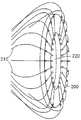
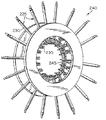
図2Aは伝送/受光束210とアイリス開口220とを含む調整可能なアイリスダイアフラム200の拡大斜視図を示す。図2Bは調整可能なアイリス組立体240の斜視図である。伝送/受光束210は例示的な束225により表示されるように一層詳細に示される。図2Bには18個の伝送/受光束225を示す。伝送/受光束225は支持構造体230、235により剛直に支持され;支持構造体230は伝送/受光束225をダイアフラム245に連結し、支持構造体235は伝送/受光束225を試験中の試片(図示せず)に接触させる。ダイアフラム245は試験中の試片にぴったり適合するように調整を行う。
FIG. 2A shows an enlarged perspective view of an
図2Cは調整可能なアイリス組立体240の接近した斜視図である。支持構造体235は、ダイアフラム245が開いたとき又は閉じたときにすべての支持体235が一緒に運動するのを保証するようにファイバポート255の下方へ延びる金属ロッド250と共に詳細に示される。ダイアフラム245は、例えば、一連の部分的に重なった可撓性のスチール板から構成することができ、可撓性のスチール板の重なり度がアイリス開口の直径を制御するように、ロッド250がスチール板に取り付けられる。この調整可能性を達成するために多数の他の構造上の変形例を利用できる。
FIG. 2C is a close-up perspective view of the
別の実施の形態においては、アイリスは固定の支持フレームで構成され、そこでは、支持体235は開口に対して進退するように軸方向に個々に運動できる。束終端の周辺への適合は作像すべき組織に対して支持体235を個々に接触又は近接させることにより達成される。
In another embodiment, the iris comprises a fixed support frame in which the
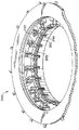
図3は外側シリンダ310と、内側シリンダ320と、受光束330と、減衰器340と、伝送束350とを含む減衰器組立体300を示す。
FIG. 3 shows an
図4Bは装着された伝送束410を備えた検出アレイ400を示す。
図5Aは二重走査ヘッド510を示す二重ブレスト(胸)スキャナーとしての本発明の実施の形態の前面図である。図5Bは調整可能なアイリス520、530、540を含む走査ヘッド510の1つの拡大側面図である。
FIG. 4B shows
FIG. 5A is a front view of an embodiment of the present invention as a dual breast scanner showing a
光源組立体100は試験中の試片の照射のためのNIR光を提供する。とりわけ、CW作動から超短時間パルスまでの範囲の、ダイオードレーザー、Ti:サフィアレーザー及びダイレーザーの如き種々のNIRレーザー102を利用できる。ファイバアレイ106内へのレーザー光の結合は、合焦レンズ104を使用してファイバの基端上に光を合焦させることにより、達成される。機械的に駆動される並進可能なファイバアレイ106は最低100個のジャケット付きファイバ束120を収容し、各ファイバ束は少なくとも2mm2 の合計活性表面積を有する多数の小径ファイバ(<200μ)を収容する。
The
伝送ファイバ束120はNIRレーザー光を伝送/受光束120を介して調整可能なアイリス組立体130内の種々の位置へ送るために使用される。
The transmission fiber bundle 120 is used to send NIR laser light through the transmit / receive bundle 120 to various locations within the
調整可能なアイリス組立体130は数個の平行で調整可能なアイリスユニットを含み、各ユニットは最低20個の伝送/受光束120を収納する。調整可能なアイリス組立体130は周囲の光を排除する役目を果たす外側ハウジングに剛直に固定される。組立体130内に収容された個々に調整可能なアイリスダイアフラムの1つを図2A、2B、2Cに示す。これらのダイアフラムは開口220内に位置する標的試片にぴったり適合し、そこでは、伝送及び受光束210が光を導き、および収集する。
光が人体組織の如き高散乱媒体内に埋もれた腫瘍の如き密度の高い物体から散乱されたとき、大きなダイナミックレンジの出射信号レベルが存在する。最強の信号は光源の近傍に直接後方散乱される信号であり;傾斜した角度で散乱され組織内で多数の反射を受ける信号は直接に後方散乱される信号よりも著しく弱い。それ故、いくつかの出射信号、特に入射光源近くの信号の減衰が必要である。断層写真測定については、これらの位置は光源の位置に従って変化する。 When light is scattered from a dense object, such as a tumor, embedded in a highly scattering medium, such as human tissue, there is a large dynamic range of outgoing signal levels. The strongest signal is the signal that is directly backscattered in the vicinity of the light source; the signal that is scattered at an inclined angle and undergoes multiple reflections in the tissue is significantly weaker than the signal that is directly backscattered. Therefore, it is necessary to attenuate some outgoing signals, especially those near the incident light source. For tomographic measurements, these positions vary according to the position of the light source.
特定されたファイバ束の選択的な減衰は図3に示す減衰器組立体300を使用して任意の光源位置に対して有効に達成できる。減衰器組立体300は2つの静止の同心的な円筒状ハウジング、即ち外側シリンダ310及び内側シリンダ320で構成され、これらシリンダ間には、複数の減衰器340を含む回転構造体が位置する。本発明の1つの実施の形態においては、減衰器は等級づけされた中立密度フィルタである。本発明の別の実施の形態においては、減衰器は偏光子である。
Selective attenuation of the identified fiber bundle can be effectively achieved for any source position using the
図3を参照すると、内側シリンダ320は調整可能なアイリス組立体130から来る受光束330の末端を収納し;これらの束は標的試片140から収集された光信号を送給する。受光束330から出射する光は減衰器340により選択的に減衰される。外側シリンダ310は伝送束350を収納し、これらの束は減衰器340から出射する光を収集し、減衰された光を図4Aに示す出力カップラーを介して図4Bに示す検出アレイ400へ導く。
Referring to FIG. 3, the
図4Aにおいて、出力カップラー420は外側装着体430及び内側装着体435により保持される。内側装着体435は装着ネジ440を介してファイバ束450を適所に保持する。ファイバ束450は光を減衰器組立体300から検出アレイ400へ送る。
In FIG. 4A, the
別の実施の形態においては、改善された信号強度は、レンズ(図示せず)を外側シリンダ310の内部に位置決めして、受光束330からの発散光を伝送束350の基端上に再合焦することにより、達成される。本発明の更に別の実施の形態においては、蛍光応用に対して、波長選択性のフィルタをもまた、励起領域(exciting field)を遮断するために受光束330と伝送束350との間に付加することができる。
In another embodiment, improved signal strength is achieved by positioning a lens (not shown) within the
減衰器340から伝送束350により収集された光は図4Bに示す検出アレイ400に導かれる。レーザー102の形式及び予期される診療応用に応じて、多数の光学検出器又は検出アレイ400の任意のものを使用できる。冷却線形CCDアレイが大半の応用にとって適している。当業者にとっては明らかなように、検出アレイ400の正面に取り付けられた適当な構造体(図示せず)は伝送束350の端部を検出アレイ400に関して固定の位置に維持して、正確な位置情報の入手を可能にする。
The light collected by the
本発明の別の態様によれば、外側ハウジングは周囲の光から本発明の内部部品を遮蔽するように設計されたブラックプラスチックで構成される。本発明の別の実施の形態は散乱流体で室を満たすことができるように特定の終端部に水密シールを形成できるラバーダムを含む。ラバーダム及び散乱流体は、ファイバと試片との間の、画像の計算に必要な境界適合条件を改善する。 According to another aspect of the present invention, the outer housing is constructed of black plastic designed to shield the internal components of the present invention from ambient light. Another embodiment of the present invention includes a rubber dam that can form a water tight seal at a particular end so that the chamber can be filled with scattering fluid. Rubber dams and scattering fluids improve the boundary fitting conditions required for image calculation between the fiber and the specimen.
本発明の別の実施の形態においては、適当ならば、左右両側の付属器官(例えば、胸や手足)の差動測定を可能にするために二重ヘッドスキャナーを使用することができる。図5Aは二重ブレスト(胸)スキャナーの前面図を示す。この実施の形態においては、本発明は2つの調整可能なアイリス組立体130を収容する二重ヘッドスキャナー510を備え、患者の両方の胸に同時に適合する。図5Bは図示の目的で3つの調整可能なアイリス520、530、540を示す、二重ヘッドスキャナー510のヘッドの1つの拡大側面図を示す。
In another embodiment of the invention, a dual head scanner can be used to allow differential measurement of the left and right appendages (eg, chest and limbs) if appropriate. FIG. 5A shows a front view of a double breasted (chest) scanner. In this embodiment, the present invention comprises a
検出アレイ400から得られる測定信号はデジタル化されてホストコンピュータへ送られ、このホストコンピュータはまた電子機器の作動、源の並進及び減衰器340の位置を制御する。ホストコンピュータはまた、再生される画像の計算及び画像表示のために使用される。
The measurement signals obtained from the
画像再生は米国特許第5,137,355号明細書で先に述べた方法を使用して達成される。これらの方法は特定のモデルを使用しての光子移転のモデリングを考察し、線形摂動(perturbation)モデルを評価する多数の利用できる代数学的解法の任意の1つを使用して測定データを分析する。 Image reproduction is accomplished using the method previously described in US Pat. No. 5,137,355. These methods consider the modeling of photon transfer using a specific model and analyze the measured data using any one of a number of available algebraic solutions that evaluate linear perturbation models. To do.
本発明の別の実施の形態においては、光源ユニット100は多重波長源(単数又は複数)を収容する。本発明の更に別の実施の形態においては、スキャナーは蛍光検出モードで作動される。
In another embodiment of the present invention, the
本発明の主要な特性のうちには、標的構造体を穏やかに一定の形状に適合させながら同時に運動部分に対して標的構造体を安定させる能力がある。後者は有利である。その理由は、一定対任意の(regular vs.arbitrary)境界を有する構造体を評価する際に数値計算で得られる改善された効率が期待できるからである。更に、他の設計上の特徴は穏やかな接触測定を許容する測定ヘッドの能力(即ち、苛酷な圧縮を必要としない)及び種々の人体構造とのインターフェイスを可能にするユニットの幾何学的な順応性を含む。 Among the key features of the present invention is the ability to stabilize the target structure against the moving portion while at the same time gently adapting the target structure to a constant shape. The latter is advantageous. The reason is that the improved efficiency obtained by the numerical calculation can be expected when evaluating a structure having a regular vs. arbitrary (regular vs. arbitrary) boundary. In addition, other design features include the ability of the measurement head to allow gentle contact measurements (ie, no severe compression is required) and the unit's geometric adaptation to allow interfacing with various body structures. Including sex.
好ましい実施の形態においては、前者は光学ファイバを取り付けた機械的なアイリスを使用して達成される。アイリスの開口の調整は完全制御の下に運動制御装置を使用して達成できる。更に、アイリスヘッドは、三次元構造体の表面測定を可能にするため、例えば実質上平行な平面内に配置されて離間したアイリスのアレイを含むように容易に拡張される。 In the preferred embodiment, the former is accomplished using a mechanical iris fitted with an optical fiber. Adjustment of the iris opening can be accomplished using the motion control device under full control. Furthermore, the iris head is easily expanded to include an array of spaced irises, eg, arranged in a substantially parallel plane, to allow surface measurements of the three-dimensional structure.
例えばレーザー源からの光学エネルギはアイリスユニットで終端する光学ファイバ内へ導入される。これは種々の方法で達成できる。1つの実施の形態においては、伝送ファイバは円筒状構造体内に収納されて円形配列として位置決めされ、この構造体の内部には、コンピュータ制御の下に回転するプリズムが位置決めされ、このプリズムが光をファイバ内へ偏向する。ファイバは束とすることができ又は適度に大きな直径(〜1mm)を有する単一のファイバで構成することができる。いずれの場合も、これらファイバは周囲の光から保護するためにジャケットで覆われる。アイリスユニット内には、受光ファイバも位置する。これらのファイバの終端は伝送ファイバの対応する光出射端部に隣接して、又は他の位置で位置決めできる。伝送/受光ファイバ配列の正確な幾何学形状は厳密なものではなく、必要なことは、どの光源ファイバに対しても十分な視野が得られるようにすることだけである。 For example, optical energy from a laser source is introduced into an optical fiber that terminates in an iris unit. This can be achieved in various ways. In one embodiment, the transmission fiber is housed in a cylindrical structure and positioned as a circular array, and within this structure is positioned a prism that rotates under computer control, which transmits light. Deflection into the fiber. The fibers can be bundled or consist of a single fiber having a reasonably large diameter (˜1 mm). In either case, these fibers are covered with a jacket to protect them from ambient light. A light receiving fiber is also located in the iris unit. The ends of these fibers can be positioned adjacent to the corresponding light exit end of the transmission fiber or at other locations. The exact geometry of the transmit / receive fiber array is not exact, all that is required is to obtain a sufficient field of view for any source fiber.
好ましい実施の形態においては、「牛の目」(bulls−eye)式に配置した二股ファイバの使用を選択した。「目」の中央部分は伝送ファイバ束を収容し;「周辺部」(halo)は受光ファイバを収容する。アイリスヘッド自体は単数又は複数のユニットで構成することができる。後者の場合、アレイ内の任意の位置で入射する光はすべての位置で標的組織から出る光となる。受け取られた光は次いで、受光ファイバを介して、任意の光源ファイバの近傍に存在する予期された高強度信号を減衰する役目を果たすフィルタユニットへ伝送される。 In the preferred embodiment, the use of bifurcated fibers arranged in a “bulls-eye” style was chosen. The central portion of the “eye” houses the transmission fiber bundle; the “periphery” (halo) houses the receiving fiber. The iris head itself can be composed of a single unit or a plurality of units. In the latter case, light incident at any position in the array becomes light that exits the target tissue at all positions. The received light is then transmitted via the receiving fiber to a filter unit that serves to attenuate the expected high intensity signal present in the vicinity of any source fiber.
光源の再位置決めを許容するため、フィルタユニットもまた、再位置決めされねばならない。これは光源ファイバの位置と同期する位置を有する可動ファイバアレイを使用して達成される。1つの実施の形態においては、2つの固定の入れ子式のシリンダが設けられ、一方のシリンダはアイリスユニットからのファイバを収納し、対向するセットは小距離離れて位置する受光ファイバを収納する。間に位置する可動フィルタアレイの位置決めは光源ファイバと同期する。フィルタユニットの別の実施の形態においては、アイリスユニットからのファイバ及び対向する受光ファイバは円形ディスク内に収納され、これらディスク間に回転するフィルタアレイが位置する。別の実施の形態においては、受け取った信号の減衰は普通源近くの信号に対してのみ必要であるが、必要なら又は所望ならば、一層離れたファイバからの信号の減衰を行うことができる。もちろん、光源ファイバに対向するこれらの受光ファイバは一層低い強度を有し、このような場合は、付加的な信号減衰は不要であり、通常は望ましくない。 The filter unit must also be repositioned to allow repositioning of the light source. This is accomplished using a movable fiber array having a position that is synchronized with the position of the source fiber. In one embodiment, two fixed telescoping cylinders are provided, one cylinder containing the fibers from the iris unit and the opposing set containing the receiving fibers located a short distance apart. The positioning of the movable filter array located in between is synchronized with the light source fiber. In another embodiment of the filter unit, the fiber from the iris unit and the opposing receiving fiber are housed in a circular disk, and a rotating filter array is located between the disks. In another embodiment, attenuation of the received signal is only required for signals near the normal source, but signal attenuation from more distant fibers can be performed if necessary or desired. Of course, these receiving fibers facing the source fiber have a lower intensity, in which case no additional signal attenuation is necessary and is usually undesirable.
フィルタユニットを通過した光は次いで光学検出器へ導かれる。ここで再度、多数の表現を使用できる。1つの場合においては、回転するフィルタを通過した光を直接受け取るように個々の検出器を位置決めできる。別の場合においては、フィルタユニット内の対向する受光ファイバに伝送された光はファイバテーパ(先細り)にインターフェイス接続でき、テーパの狭い端部は二次元CCD又はCID検出器の如き領域検出器に接触して配置される。 The light that has passed through the filter unit is then directed to an optical detector. Here again, a number of expressions can be used. In one case, individual detectors can be positioned to directly receive light that has passed through a rotating filter. In another case, the light transmitted to the opposite receiving fiber in the filter unit can be interfaced to a fiber taper, with the narrow end of the taper contacting an area detector such as a two-dimensional CCD or CID detector. Arranged.
説明した装置は幾何学的に適応できるインターフェイス装置を提示するものとして適当に見ることができる。一端には光源があり、他端には検出器がある。その間には、アイリスユニット及びアイリスへ光を導き、どんな必要な信号調整(即ち、減衰)をも遂行する付随的な装置が位置する。従って、このユニットはDC(直流)振幅調整源又はパルス源の如きいかなる光源状態をも容易に許容できる。これはまた、選択された光源の条件に適したどんな検出器をも容易に許容する。 The described device can be suitably viewed as presenting a geometrically adaptable interface device. There is a light source at one end and a detector at the other end. In between are the iris units and ancillary devices that direct light to the iris and perform any necessary signal conditioning (ie, attenuation). Therefore, this unit can easily tolerate any light source condition such as a DC (direct current) amplitude adjustment source or a pulse source. This also readily allows any detector suitable for the selected light source conditions.
実際には、アイリスユニット自体は好ましくは周囲の光からこれを遮蔽するシェル内に収納される。また、アイリスヘッド内への散乱流体の導入を許容して境界状態を簡略化するように構成することができる。後者の場合、標的組織とのインターフェイス接続にラバーアームの形をした液密シールが必要となる。 In practice, the iris unit itself is preferably housed in a shell that shields it from ambient light. Further, the boundary state can be simplified by allowing the scattering fluid to be introduced into the iris head. In the latter case, a liquid tight seal in the form of a rubber arm is required for interface connection with the target tissue.
上述の装置から得られた測定データは続いて335号特許において先に説明したように分析される。基本的には、ほぼ任意の型式の摂動方法を採用できる。典型的には、これらはある型式の代数学的再生方法を実行する。解法は第1等級ボバ又はリトフ(First−Order Bova orRytov) の近似値に制限することができ、または、反復性のニュートン式の解法を採用することができる。認識されるように、後者の場合、一定の幾何学形状から得られた測定データは任意の境界を有する物体から得られたデータよりも一層有効に分析できる。これは本発明のアイリスユニットにより達成される1つの重要な特徴である。 The measurement data obtained from the device described above is subsequently analyzed as previously described in the '335 patent. Basically, almost any type of perturbation method can be employed. Typically they perform some type of algebraic regeneration method. The solution can be limited to first-order Boba or First-Order Bova or Rytov approximations, or iterative Newtonian solutions can be employed. As will be appreciated, in the latter case, measurement data obtained from a certain geometric shape can be analyzed more effectively than data obtained from an object with arbitrary boundaries. This is one important feature achieved by the iris unit of the present invention.
画像を再生するための測定データの分析とは別に、また、特徴抽出プログラムに従ってデータを独立に分析できることを理解すべきである。基本的には、試験物体(例えば、胸)の外部形状が一定で既知であるため、これが断層写真データセット内の多数の可能なパターンを制限する傾向を有することが認識される。推測的に、異なる病理が組織内での光伝播に異なる影響を与えるものと予期することは妥当である。標的の外部形状が大きく制限されている(例えば、円)場合は、データ内の可能なパターンの範囲も同様に制限されることがある。従って、運動部分に対するガードとは別に、アイリスユニットは特徴抽出問題のような画像回復問題を分析するのに十分適したデータの測定を当然可能にする。特徴抽出は逆伝播の如き標準の神経網体系を使用して容易に評価される。この場合の訓練ベクトル(training vectors)(即ち、常態データ)は既知で十分明確な病理を持つ患者について行った測定から導き出される。 It should be understood that the data can be analyzed independently of the analysis of the measurement data to reproduce the image and according to the feature extraction program. It is basically recognized that since the external shape of the test object (eg, breast) is constant and known, this tends to limit the number of possible patterns in the tomographic data set. Presumably, it is reasonable to expect that different pathologies will have different effects on light propagation in tissues. If the external shape of the target is greatly limited (eg, a circle), the range of possible patterns in the data may be limited as well. Thus, apart from guarding against moving parts, the iris unit naturally allows measurement of data that is well-suited for analyzing image recovery problems such as feature extraction problems. Feature extraction is easily evaluated using standard neural network systems such as back propagation. The training vectors (ie, normal data) in this case are derived from measurements made on a patient with a known and well-defined pathology.
人体組織についての測定に対しては、試験中の標的が不均一な境界を有し、運動部分を持つ傾向があるものと予期することができる。例えば、これは確かに胸の非接触測定を包含する場合となろう。胸は変形可能な構造である。その外側形状は対象物の方位及び支持構造体の存在に従って変化する。更に、呼吸及び心臓活動が不安定な部分を生じさせるものと予期することができる。 For measurements on human tissue, it can be expected that the target under test has a non-uniform boundary and tends to have a moving part. For example, this would certainly include a non-contact measurement of the breast. The breast is a deformable structure. Its outer shape changes according to the orientation of the object and the presence of the support structure. Furthermore, it can be expected that breathing and cardiac activity will produce unstable parts.
これらの型式の変数は良質の画像を達成する際に問題となることがある。運動部分は画質を劣化させる測定データ内のノイズの原因となる。355号特許の方法論は不均一境界を有する構造体を評価できるが、この型式の問題(例えば、限定差(finitedifferences)、限定要素解決策(finiteelement solvents )に適用できる数値方法は、外部境界が円滑で一定(例えば、円筒形、半球形形状)の場合は、一層有効である。これは、多重グリッド前進ソルバー(multi−grid forward solvers)の使用が計算時間を大幅に減少できるような反対の問題の反復解決を包含する場合に特に真実である。従って、本発明は運動部分を最小化し、同時に標的構造体の外部形状を簡単な形状に適合させる必要性に向けられる。測定装置が幾何学的に適応できるので、種々の人体構造に対する測定が可能になる。 These types of variables can be problematic in achieving good quality images. The moving part causes noise in the measurement data that degrades the image quality. Although the methodology of the '355 patent can evaluate structures with non-uniform boundaries, numerical methods that can be applied to this type of problem (eg, limited differences, finite element solutions) have smooth outer boundaries. And constant (eg, cylindrical, hemispherical shapes) is even more effective, which is the opposite problem that the use of multi-grid forward solvers can significantly reduce computation time Therefore, the present invention is directed to the need to minimize the moving part and at the same time adapt the external shape of the target structure to a simple shape. Therefore, it is possible to measure various human body structures.
要約すると、ここで述べた装置は従来の光学スキャナーに比べて改善された信号忠実度を提供する。本発明の好ましい実施の形態においては、適合構造体は、人体組織に軽度ないし適度な圧縮を与えながら、多数の光学ファイバを皮膚に直接接触させることのできる調整可能な多重層アイリスフレーム内に収納された光学ファイバ基礎の断層写真組立体を有する。このデザインはいくつかの有用な目的にかなう。これはデータ取得中の組織構造を機械的に安定させるように作用し、運動部分を最小化する。ある状況においては、これはまた、組織をアイリス開口の形状にさせる。これは改善された信号収集を可能にすると同時に、標的媒体の形状に関する光学ファイバの位置の正確な知得を可能にする。組織の形状に関して各多重層アイリスの開口を調整することにより、不均一人体構造(例えば、胸)に対する正確な輪郭づけを達成できる。全体のアイリス組立体は、周囲の光を遮断する役目を果たす一層大きなフレーム内に剛直に収納され、このフレームは改善された境界適合を可能にするために散乱流体で満たすことができる。 In summary, the apparatus described here provides improved signal fidelity compared to conventional optical scanners. In a preferred embodiment of the invention, the conforming structure is housed in an adjustable multilayer iris frame that allows multiple optical fibers to be in direct contact with the skin while imparting moderate to moderate compression to human tissue. An optical fiber based tomographic assembly. This design serves several useful purposes. This acts to mechanically stabilize the tissue structure during data acquisition and minimizes the moving part. In some situations, this also causes the tissue to be in the shape of an iris opening. This allows for improved signal acquisition while at the same time accurately knowing the position of the optical fiber with respect to the shape of the target medium. By adjusting the opening of each multi-layer iris with respect to the shape of the tissue, an accurate contour for a non-uniform human body structure (eg, breast) can be achieved. The entire iris assembly is rigidly housed in a larger frame that serves to block ambient light, and this frame can be filled with scattering fluid to allow improved boundary fitting.
ここに開示した装置は、低コストの光学スキャナーを使用しての、種々の病理状態の検出及び作像(例えば、癌診断及び計画、酸素欠乏状態の評価、血管病理等)のための厚い組織構造のNIR光学断層写真作像研究を可能にする。更に、装置は、不均一形状の高精度、高感度の測定を可能にするように355号特許の基本概念を改良しながら、これらの概念を使用する。 The device disclosed herein uses thick tissue for detection and imaging of various pathological conditions (eg, cancer diagnosis and planning, evaluation of hypoxia, vascular pathology, etc.) using a low cost optical scanner. Enables NIR optical tomography imaging studies of structures. In addition, the device uses these concepts while improving the basic concept of the '355 patent to allow for highly accurate and sensitive measurements of non-uniform shapes.
新しい装置はまた、大きな融通性を有し、既に述べたように、大人の種々の人体部位(例えば、胸、手足、生殖器、頭及び首)の評価、及び、可能なら、幼児の全人体の評価に容易に適用できる。この装置はまた、獣医学用途、例えば競走馬の如き動物の四肢や関節の評価にも適用できる。 The new device also has great flexibility and, as already mentioned, the assessment of various human body parts (eg chest, limbs, genitals, head and neck) and, if possible, the whole body of the infant. Can be easily applied to evaluation. This device can also be applied to veterinary applications, such as the evaluation of limbs and joints of animals such as racehorses.
開示されたユニットは軽量で、小型で、控えめなパワー要求を有し、低コストの光源及び検出器を使用する。更に、断層写真データの収集は最小量の機械動作で達成される。生産ユニットは実験用カート上に容易に取り付けできると期待される。単数対複数波長の光学及び蛍光測定並びに二重ヘッドユニットの如き代わりの実施の形態のために小さな修正が必要となることがある。本発明の範囲は医療分野に限定されず、濃密な媒体内に埋もれた物体の三次元作像、例えば食品の遠隔検査を含む任意の応用を包含することができる。 The disclosed unit is lightweight, small, has modest power requirements, and uses low cost light sources and detectors. Furthermore, the collection of tomographic data is achieved with a minimum amount of machine movement. Production units are expected to be easily mounted on a laboratory cart. Small modifications may be required for alternative embodiments such as single to multiple wavelength optical and fluorescence measurements and dual head units. The scope of the present invention is not limited to the medical field and can encompass any application including three-dimensional imaging of an object embedded in a dense medium, such as remote inspection of food.
本発明の利点は、組織の外部形状及び光源や検出器の位置の知得における誤差に対する画像精度及び安定性の感度並びに運動部分に対する感度の認識である。 An advantage of the present invention is the recognition of image accuracy and stability sensitivity to errors in the knowledge of the external shape of the tissue and the location of light sources and detectors, and sensitivity to moving parts.
本発明の更なる利点は、NIR光を光学ファイバ内に結合するために種々の光学(レーザー)源を使用できることである。 A further advantage of the present invention is that various optical (laser) sources can be used to couple the NIR light into the optical fiber.
本発明の例示的な実施の形態及びその種々の修正例を添付図面につきここで詳細に説明したが、本発明はこの正確な実施の形態及び述べられた修正例に限定されず、特許請求の範囲に規定された本発明の範囲又は精神から逸脱することなく種々の変更及び更なる修正が可能であることを理解すべきである。 While exemplary embodiments of the present invention and various modifications thereof have been described in detail herein with reference to the accompanying drawings, the present invention is not limited to this precise embodiment and described modifications, but is claimed. It should be understood that various changes and further modifications can be made without departing from the scope or spirit of the invention as defined in the scope.
Claims (44)
組織を通して少なくとも減衰伝送を行うことのできる波長を有する光を提供できる光源と;
上記光源から作像すべき組織へ光を伝送するためのファイバ束を含む第1のファイバアレイと;
組織により散乱された光を収集するファイバ束を含む第2のファイバアレイと;
各ファイバ束の一端を支持する少なくとも1つの調整可能な支持部材を含む調整可能な組立体であって、上記各ファイバ束が上記第1及び第2のファイバアレイからのものであって、多数の離間した地点で作像される組織の表面内へ光を伝送しかつ当該表面から出射する光を収集するように、上記各ファィバ束を作像されている組織の表面に適合すべく上記1つ以上の調整可能な各支持部材の部分に沿って分布させるよう構成された組立体と;
上記第2のファイバアレイのファイバにより収集された散乱された光を収集する検出アレイと;
を有することを特徴とする装置。 In an apparatus for optically tomographic imaging of a tissue structure having a non-uniform surface shape,
A light source capable of providing light having a wavelength capable of at least attenuated transmission through tissue;
A first fiber array including a fiber bundle for transmitting light from the light source to the tissue to be imaged;
A second fiber array including a fiber bundle that collects light scattered by the tissue;
An adjustable assembly including at least one adjustable support member that supports one end of each fiber bundle, wherein each fiber bundle is from the first and second fiber arrays and includes a plurality of Each of the fiber bundles is adapted to conform to the surface of the tissue being imaged so as to transmit light into and collect light emanating from the surface of the tissue imaged at spaced points. An assembly configured to be distributed along a portion of each of the adjustable support members;
A detection array for collecting scattered light collected by the fibers of the second fiber array;
A device characterized by comprising:
上記第2のファイバアレイの上記ファイバ束の他端を収納する内側シリンダと;
光を上記検出アレイに導く複数の上記ファイバ束の一端を収納する外側シリンダと;
上記内側及び外側シリンダ間に位置する複数の減衰器と;
を有することを特徴とする請求項8に記載の装置。 The attenuator is
An inner cylinder that houses the other end of the fiber bundle of the second fiber array;
An outer cylinder that houses one end of the plurality of fiber bundles that guide light to the detection array;
A plurality of attenuators located between the inner and outer cylinders;
9. The device of claim 8, comprising:
組織を通して少なくとも減衰伝送を行うことのできる波長を有する光を提供できる光源と; A light source capable of providing light having a wavelength capable of at least attenuated transmission through tissue;
上記光源から作像すべき組織へ光を伝送するためのファイバ束を含む第1のファイバアレイと; A first fiber array including a fiber bundle for transmitting light from the light source to the tissue to be imaged;
組織により散乱された光を収集するファイバ束を含む第2のファイバアレイと; A second fiber array including a fiber bundle that collects light scattered by the tissue;
各ファイバ束の一端を支持する少なくとも1つの調整可能な支持部材を含む調整可能な組立体であって、上記各ファイバ束が上記第1及び第2のファイバアレイからのものであって、多数の離間した地点で作像される組織の表面内へ光を伝送しかつ当該表面から出射する光を収集するように、上記各ファィバ束を作像されている組織の表面に適合すべく上記1つ以上の調整可能な各支持部材の部分に沿って分布させるよう構成された組立体と; An adjustable assembly including at least one adjustable support member that supports one end of each fiber bundle, wherein each fiber bundle is from the first and second fiber arrays and includes a plurality of Each of the fiber bundles is adapted to fit the surface of the tissue being imaged so as to transmit light into and collect light emanating from the surface of the tissue imaged at the spaced point. An assembly configured to be distributed along a portion of each of the adjustable support members;
上記第2のファイバアレイのファイバにより収集された主に定常の散乱光を受け取る検出アレイと; A detection array that receives primarily stationary scattered light collected by the fibers of the second fiber array;
を有することを特徴とする装置。A device characterized by comprising:
上記第2のファイバアレイの上記ファイバ束の他端を収納する内側シリンダと; An inner cylinder that houses the other end of the fiber bundle of the second fiber array;
光を上記検出アレイに導く複数の上記ファイバ束の一端を収納する外側シリンダと; An outer cylinder that houses one end of the plurality of fiber bundles that guide light to the detection array;
上記内側及び外側シリンダ間に位置する複数の減衰器と; A plurality of attenuators located between the inner and outer cylinders;
を有することを特徴とする請求項29に記載の装置。30. The apparatus of claim 29, comprising:
組織を通して少なくとも減衰伝送を行うことのできる波長を有する光を提供できる光源と; A light source capable of providing light having a wavelength capable of at least attenuated transmission through tissue;
上記光源から作像すべき組織へ光を伝送するためのファイバ束を含む第1のファイバアレイと; A first fiber array including a fiber bundle for transmitting light from the light source to the tissue to be imaged;
組織により散乱された光を収集するファイバ束を含む第2のファイバアレイと; A second fiber array including a fiber bundle that collects light scattered by the tissue;
各ファイバ束の一端を支持する少なくとも1つの調整可能な支持部材を含む調整可能な組立体であって、上記各ファイバ束が上記第1及び第2のファイバアレイからのものであって、多数の離間した地点で作像される組織の表面内へ光を伝送しかつ当該表面から出射する光を収集するように、作像されている組織構造を一定の形状に適合する上記1つ以上の調整可能な各支持部材の部分に沿って分布させるよう構成された組立体と; An adjustable assembly including at least one adjustable support member that supports one end of each fiber bundle, wherein each fiber bundle is from the first and second fiber arrays and includes a plurality of The one or more adjustments that conform the imaged tissue structure to a certain shape so as to transmit light into and collect light emitted from the surface of the tissue imaged at spaced points An assembly configured to be distributed along a portion of each possible support member;
上記第2のファイバアレイのファイバにより収集された散乱された光を収集する検出アレイと; A detection array for collecting scattered light collected by the fibers of the second fiber array;
を有することを特徴とする装置。A device characterized by comprising:
Applications Claiming Priority (2)
| Application Number | Priority Date | Filing Date | Title |
|---|---|---|---|
| US08/951,892 US6081322A (en) | 1997-10-16 | 1997-10-16 | NIR clinical opti-scan system |
| US08/951,892 | 1997-10-16 |
Related Parent Applications (1)
| Application Number | Title | Priority Date | Filing Date |
|---|---|---|---|
| JP2000517267A Division JP2001521147A (en) | 1997-10-16 | 1998-10-05 | Near-infrared medical optical scanning device |
Publications (2)
| Publication Number | Publication Date |
|---|---|
| JP2010101902A true JP2010101902A (en) | 2010-05-06 |
| JP5342992B2 JP5342992B2 (en) | 2013-11-13 |
Family
ID=25492285
Family Applications (2)
| Application Number | Title | Priority Date | Filing Date |
|---|---|---|---|
| JP2000517267A Pending JP2001521147A (en) | 1997-10-16 | 1998-10-05 | Near-infrared medical optical scanning device |
| JP2009288287A Expired - Fee Related JP5342992B2 (en) | 1997-10-16 | 2009-12-18 | Near-infrared medical optical scanner |
Family Applications Before (1)
| Application Number | Title | Priority Date | Filing Date |
|---|---|---|---|
| JP2000517267A Pending JP2001521147A (en) | 1997-10-16 | 1998-10-05 | Near-infrared medical optical scanning device |
Country Status (8)
| Country | Link |
|---|---|
| US (2) | US6081322A (en) |
| EP (1) | EP1023584B1 (en) |
| JP (2) | JP2001521147A (en) |
| CN (1) | CN1211650C (en) |
| AT (1) | ATE258678T1 (en) |
| CA (1) | CA2306922C (en) |
| DE (1) | DE69821380T2 (en) |
| WO (1) | WO1999020997A1 (en) |
Families Citing this family (55)
| Publication number | Priority date | Publication date | Assignee | Title |
|---|---|---|---|---|
| US6274086B1 (en) * | 1996-12-16 | 2001-08-14 | The Trustees Of The University Of Pennsylvania | Apparatus for non-invasive imaging oxygen distribution in multi-dimensions |
| US6592847B1 (en) * | 1998-05-14 | 2003-07-15 | The General Hospital Corporation | Intramolecularly-quenched near infrared flourescent probes |
| EP1207385B1 (en) * | 1999-06-03 | 2011-02-09 | Hamamatsu Photonics K.K. | Optical ct device and method of image reformation |
| EP1609410B1 (en) * | 1999-06-03 | 2014-05-28 | Hamamatsu Photonics K.K. | Optical CT apparatus |
| JP2003509687A (en) * | 1999-09-14 | 2003-03-11 | ザ・リサーチ・ファンデーション・オブ・ステート・ユニバーシティ・オブ・ニューヨーク | System and method for tomographic imaging of dynamic properties of scattering media |
| US6795195B1 (en) * | 1999-09-14 | 2004-09-21 | Research Foundation Of State University Of New York | System and method for tomographic imaging of dynamic properties of a scattering medium |
| US20010032053A1 (en) * | 2000-01-24 | 2001-10-18 | Hielscher Andreas H. | Imaging of a scattering medium using the equation of radiative transfer |
| US6615063B1 (en) * | 2000-11-27 | 2003-09-02 | The General Hospital Corporation | Fluorescence-mediated molecular tomography |
| US7383076B2 (en) * | 2000-11-27 | 2008-06-03 | The General Hospital Corporation | Fluorescence-mediated molecular tomography |
| US20030044353A1 (en) * | 2001-01-05 | 2003-03-06 | Ralph Weissleder | Activatable imaging probes |
| US6944322B2 (en) * | 2001-03-28 | 2005-09-13 | Visiongate, Inc. | Optical tomography of small objects using parallel ray illumination and post-specimen optical magnification |
| US6965108B2 (en) * | 2001-07-30 | 2005-11-15 | Euro-Celtique, S.A. | Method and apparatus for three dimensional imaging using infrared radiation |
| US6662128B2 (en) * | 2002-01-18 | 2003-12-09 | The Research Foundation Of State University Of New York | Normalized-constraint algorithm for minimizing inter-parameter crosstalk in imaging of scattering media |
| CA2481518A1 (en) * | 2002-04-06 | 2003-10-23 | Randall L. Barbour | A system and method for quantifying the dynamic response of a target system |
| WO2003088133A1 (en) * | 2002-04-06 | 2003-10-23 | Barbour Randall L | Modification of the normalized difference method for real-time optical tomography |
| US7636413B2 (en) * | 2002-04-16 | 2009-12-22 | General Electric Company | Method and apparatus of multi-energy imaging |
| EP2410315B1 (en) | 2002-06-04 | 2020-04-01 | Visen Medical, Inc. | Imaging volumes with arbitrary geometries in contact and non-contact tomography |
| US6784988B2 (en) * | 2002-07-17 | 2004-08-31 | Hamilton Associates, Inc. | Apparatus and process for analyzing a stream of fluid |
| US7647091B2 (en) * | 2003-02-05 | 2010-01-12 | The General Hospital Corporation | Method and system for free space optical tomography of diffuse media |
| US7359540B2 (en) * | 2003-06-27 | 2008-04-15 | Ge Medical Systems Global Technology Company, Llc | Systems and methods for correcting inhomogeneity in images |
| CN100403985C (en) * | 2004-04-09 | 2008-07-23 | 清华大学 | Digital near-infrared diffusion fault imaging system |
| AU2005265048B2 (en) | 2004-06-18 | 2011-06-16 | Elamleh, David R. | Intravascular imaging device and uses thereof |
| WO2006014736A2 (en) * | 2004-07-21 | 2006-02-09 | Barbour Randall L | Method and system for temporal spectral imaging |
| WO2007016048A2 (en) * | 2005-07-27 | 2007-02-08 | University Of Massachusetts Lowell | Infrared scanner for biological applications |
| FR2895897B1 (en) * | 2006-01-12 | 2008-10-17 | Commissariat Energie Atomique | METHOD AND DEVICE FOR RECONSTRUCTING OPTICAL TOMOGRAPHY IMAGE OF DOUBLE-MEASURING FLUORESCENCE |
| FR2895896A1 (en) * | 2006-01-12 | 2007-07-13 | Commissariat Energie Atomique | Optical tomography image reconstructing method for e.g. imaging of small animal, involves acquiring images by detecting light emitted by object`s surfaces, respectively, and reconstructing distribution of fluorophores in object using images |
| US9889043B2 (en) * | 2006-01-20 | 2018-02-13 | Lensar, Inc. | System and apparatus for delivering a laser beam to the lens of an eye |
| US7796260B1 (en) * | 2006-04-25 | 2010-09-14 | J.A. Woollam Co., Inc. | System and method of controlling intensity of an electromagnetic beam |
| WO2008039988A2 (en) * | 2006-09-28 | 2008-04-03 | The Florida International University Board Of Trustees | Hand-held optical probe based imaging system with 3d tracking facilities |
| US8712504B2 (en) * | 2006-09-28 | 2014-04-29 | The Florida International University Board Of Trustees | Hand-held optical probe based imaging system with 3D tracking facilities |
| US8323694B2 (en) * | 2007-05-09 | 2012-12-04 | Nanoprobes, Inc. | Gold nanoparticles for selective IR heating |
| TW200906478A (en) * | 2007-08-09 | 2009-02-16 | Univ Nat Central | Method for preparing mesocrystals by organic and organometallic compounds |
| EP3320923B1 (en) | 2008-01-18 | 2022-04-06 | Visen Medical, Inc. | Fluorescent imaging agents |
| US20110059023A1 (en) * | 2008-03-19 | 2011-03-10 | Tunnell James W | Narrowband imaging using near-infrared absorbing nanoparticles |
| DE102009044303B4 (en) * | 2009-10-21 | 2012-04-19 | Karlsruher Institut für Technologie | Fast optical tomography |
| CA2781393C (en) | 2009-11-19 | 2017-08-08 | Modulated Imaging, Inc. | Method and apparatus for analysis of turbid media via single-element detection using structured illumination |
| US20110123452A1 (en) * | 2009-11-25 | 2011-05-26 | Nanoprobes, Inc. | Metal oligomers and polymers and their use in biology and medicine |
| US9635349B2 (en) | 2010-06-11 | 2017-04-25 | The Florida International University Board Of Trustees | Second generation hand held optical imager |
| US8378302B2 (en) * | 2010-10-11 | 2013-02-19 | National Central University | Bidirectional optical scanner assisting in mammography |
| US10376150B2 (en) * | 2011-09-30 | 2019-08-13 | The Trustees Of Columbia University In The City Of New York | Interfacing systems, devices, and methods for optical imaging |
| US10674918B2 (en) | 2012-01-06 | 2020-06-09 | The Florida International University Board Of Trustees | Near-infrared (NIR) optical scanner |
| US20130237787A1 (en) * | 2012-03-12 | 2013-09-12 | Ivwatch, Llc | Apparatus and Method for Mitigating Noise Affecting a Transcutaneous Signal |
| US20130237850A1 (en) * | 2012-03-12 | 2013-09-12 | Ivwatch, Llc | Geometry of a Transcutaneous Sensor |
| BR112015010459B1 (en) | 2012-11-07 | 2021-01-26 | Modulated Imaging, Inc. | method for measuring a cloudy sample |
| TWI572331B (en) * | 2012-12-28 | 2017-03-01 | 國立交通大學 | Rotation type optical fault scanner |
| WO2015103614A2 (en) | 2014-01-06 | 2015-07-09 | The Florida International University Board Of Trustees | Near infrared optical imaging system for hemodynamic imaging, pulse monitoring, and mapping spatio-temporal features |
| USD763938S1 (en) | 2014-04-02 | 2016-08-16 | Cephalogics, LLC | Optical sensor array |
| USD763939S1 (en) | 2014-04-02 | 2016-08-16 | Cephalogics, LLC | Optical sensor array liner with optical sensor array pad |
| WO2015174975A1 (en) * | 2014-05-15 | 2015-11-19 | Ohio State Innovation Foundation | Active control guards and rationometric calibration and reconstruction for use with electrical capacitance volume tomography |
| TWI577345B (en) * | 2015-02-09 | 2017-04-11 | 國立中央大學 | A circular scanning device for optical tomography systems |
| CN105938101B (en) * | 2016-04-14 | 2020-12-11 | 中国科学院力学研究所 | Imaging system and method for flame three-dimensional reconstruction based on chemiluminescence |
| JP7297891B2 (en) | 2018-07-19 | 2023-06-26 | アクティブ サージカル, インコーポレイテッド | Systems and Methods for Multimodal Sensing of Depth in Vision Systems for Automated Surgical Robots |
| KR20220021920A (en) | 2019-04-08 | 2022-02-22 | 액티브 서지컬, 인크. | Systems and methods for medical imaging |
| US11304456B2 (en) | 2019-07-28 | 2022-04-19 | Holovisions LLC | Smart bra with optical sensors to detect abnormal breast tissue |
| US11950881B2 (en) | 2019-07-28 | 2024-04-09 | Holovsions LLC | Smart bra for optical scanning of breast tissue to detect abnormal tissue with selectively-expandable components to reduce air gaps |
Citations (13)
| Publication number | Priority date | Publication date | Assignee | Title |
|---|---|---|---|---|
| JPH03218443A (en) * | 1989-11-21 | 1991-09-26 | Toshiba Corp | Tomographic image pickup method and device using beam |
| JPH0454439A (en) * | 1990-06-22 | 1992-02-21 | Hitachi Ltd | Method and instrument for measuring living body |
| JPH04122248A (en) * | 1990-09-13 | 1992-04-22 | Res Dev Corp Of Japan | Optical tomographic image imaging device |
| JPH05184580A (en) * | 1992-01-16 | 1993-07-27 | Toshiba Corp | Optical ct device |
| JPH05223738A (en) * | 1992-02-14 | 1993-08-31 | Res Dev Corp Of Japan | Measuring device for fluorescent tomographic image |
| JPH06506127A (en) * | 1991-01-24 | 1994-07-14 | ノン―インヴェイシヴ テクノロジイ,インク. | Time and frequency domain spectrometer to measure hypoxia |
| JPH06221913A (en) * | 1992-10-06 | 1994-08-12 | Hamamatsu Photonics Kk | Method and equipment for measuring optical information of scatterer/absorber |
| JPH0749304A (en) * | 1993-06-02 | 1995-02-21 | Hamamatsu Photonics Kk | Method and apparatus for measuring internal information of scattering absorbent |
| JPH07151673A (en) * | 1993-11-30 | 1995-06-16 | Hitachi Ltd | System and method for optical calculation tomography |
| JPH0829329A (en) * | 1994-07-14 | 1996-02-02 | Hitachi Ltd | Spatial distribution imaging method for concentration of absorbing substance |
| JPH08166341A (en) * | 1994-12-14 | 1996-06-25 | Technol Res Assoc Of Medical & Welfare Apparatus | Optical ct |
| JPH08334458A (en) * | 1995-06-05 | 1996-12-17 | Technol Res Assoc Of Medical & Welfare Apparatus | Detector holder for photometer |
| US5625458A (en) * | 1994-11-10 | 1997-04-29 | Research Foundation Of City College Of New York | Method and system for imaging objects in turbid media using diffusive fermat photons |
Family Cites Families (5)
| Publication number | Priority date | Publication date | Assignee | Title |
|---|---|---|---|---|
| US5137355A (en) * | 1988-06-08 | 1992-08-11 | The Research Foundation Of State University Of New York | Method of imaging a random medium |
| US5353799A (en) * | 1991-01-22 | 1994-10-11 | Non Invasive Technology, Inc. | Examination of subjects using photon migration with high directionality techniques |
| US5213105A (en) * | 1990-12-04 | 1993-05-25 | Research Corporation Technologies, Inc. | Frequency domain optical imaging using diffusion of intensity modulated radiation |
| WO1994005209A1 (en) * | 1992-08-31 | 1994-03-17 | Hitachi, Ltd. | Optical ct apparatus |
| US5876339A (en) * | 1997-01-09 | 1999-03-02 | Lemire; Robert | Apparatus for optical breast imaging |
-
1997
- 1997-10-16 US US08/951,892 patent/US6081322A/en not_active Ceased
-
1998
- 1998-10-05 JP JP2000517267A patent/JP2001521147A/en active Pending
- 1998-10-05 DE DE69821380T patent/DE69821380T2/en not_active Expired - Lifetime
- 1998-10-05 EP EP98949750A patent/EP1023584B1/en not_active Expired - Lifetime
- 1998-10-05 CN CN98810247.1A patent/CN1211650C/en not_active Expired - Fee Related
- 1998-10-05 CA CA002306922A patent/CA2306922C/en not_active Expired - Fee Related
- 1998-10-05 AT AT98949750T patent/ATE258678T1/en not_active IP Right Cessation
- 1998-10-05 WO PCT/US1998/020810 patent/WO1999020997A1/en active IP Right Grant
-
2002
- 2002-06-27 US US10/183,276 patent/USRE38800E1/en not_active Expired - Lifetime
-
2009
- 2009-12-18 JP JP2009288287A patent/JP5342992B2/en not_active Expired - Fee Related
Patent Citations (13)
| Publication number | Priority date | Publication date | Assignee | Title |
|---|---|---|---|---|
| JPH03218443A (en) * | 1989-11-21 | 1991-09-26 | Toshiba Corp | Tomographic image pickup method and device using beam |
| JPH0454439A (en) * | 1990-06-22 | 1992-02-21 | Hitachi Ltd | Method and instrument for measuring living body |
| JPH04122248A (en) * | 1990-09-13 | 1992-04-22 | Res Dev Corp Of Japan | Optical tomographic image imaging device |
| JPH06506127A (en) * | 1991-01-24 | 1994-07-14 | ノン―インヴェイシヴ テクノロジイ,インク. | Time and frequency domain spectrometer to measure hypoxia |
| JPH05184580A (en) * | 1992-01-16 | 1993-07-27 | Toshiba Corp | Optical ct device |
| JPH05223738A (en) * | 1992-02-14 | 1993-08-31 | Res Dev Corp Of Japan | Measuring device for fluorescent tomographic image |
| JPH06221913A (en) * | 1992-10-06 | 1994-08-12 | Hamamatsu Photonics Kk | Method and equipment for measuring optical information of scatterer/absorber |
| JPH0749304A (en) * | 1993-06-02 | 1995-02-21 | Hamamatsu Photonics Kk | Method and apparatus for measuring internal information of scattering absorbent |
| JPH07151673A (en) * | 1993-11-30 | 1995-06-16 | Hitachi Ltd | System and method for optical calculation tomography |
| JPH0829329A (en) * | 1994-07-14 | 1996-02-02 | Hitachi Ltd | Spatial distribution imaging method for concentration of absorbing substance |
| US5625458A (en) * | 1994-11-10 | 1997-04-29 | Research Foundation Of City College Of New York | Method and system for imaging objects in turbid media using diffusive fermat photons |
| JPH08166341A (en) * | 1994-12-14 | 1996-06-25 | Technol Res Assoc Of Medical & Welfare Apparatus | Optical ct |
| JPH08334458A (en) * | 1995-06-05 | 1996-12-17 | Technol Res Assoc Of Medical & Welfare Apparatus | Detector holder for photometer |
Also Published As
| Publication number | Publication date |
|---|---|
| DE69821380D1 (en) | 2004-03-04 |
| CA2306922C (en) | 2009-03-17 |
| USRE38800E1 (en) | 2005-09-20 |
| EP1023584A1 (en) | 2000-08-02 |
| WO1999020997A1 (en) | 1999-04-29 |
| US6081322A (en) | 2000-06-27 |
| JP2001521147A (en) | 2001-11-06 |
| DE69821380T2 (en) | 2004-12-09 |
| CN1211650C (en) | 2005-07-20 |
| JP5342992B2 (en) | 2013-11-13 |
| CN1276869A (en) | 2000-12-13 |
| CA2306922A1 (en) | 1999-04-29 |
| EP1023584B1 (en) | 2004-01-28 |
| ATE258678T1 (en) | 2004-02-15 |
Similar Documents
| Publication | Publication Date | Title |
|---|---|---|
| JP5342992B2 (en) | Near-infrared medical optical scanner | |
| US20210321874A1 (en) | Transcranial photoacoustic/thermoacoustic tomography brain imaging informed by adjunct image data | |
| JP6174658B2 (en) | Hand-held device and method for tomographic photoacoustic imaging of an object | |
| JP5808741B2 (en) | Imaging apparatus and method for photoacoustic imaging of small animals | |
| CA2708675C (en) | Three-dimensional photoacoustic imager and methods for calibrating an imager | |
| JP5294998B2 (en) | Ultrasonic probe, photoacoustic / ultrasonic system including the ultrasonic probe, and specimen imaging apparatus | |
| KR102170350B1 (en) | System and method for producing parametric maps of optoacoustic data | |
| US20110306865A1 (en) | photoacoustic imaging device | |
| JP2013500091A5 (en) | ||
| EP2527815B1 (en) | Thermoacoustic imaging with quantitative extraction of an absorption image | |
| JP7082383B2 (en) | Inspection equipment and inspection method that combines tactile sensor and optical tomography | |
| WO2014073907A1 (en) | Photoacoustic scanning apparatus for breast cancer diagnosis | |
| CN107530046B (en) | Diffuse acoustic confocal imager | |
| Ai | Photoacoustic tomography for prostate imaging by transurethral illumination | |
| Haupt et al. | Non-Contact Optical Ultrasound Concept for Biomedical Imaging | |
| JP2015091347A (en) | Ultrasonic probe, photoacoustic and ultrasonic system having the same, and specimen imaging device | |
| JPH04319345A (en) | Photo-tomographic imaging system | |
| KR20120074904A (en) | Coupling pad and photoacoustic system |
Legal Events
| Date | Code | Title | Description |
|---|---|---|---|
| A621 | Written request for application examination |
Free format text: JAPANESE INTERMEDIATE CODE: A621 Effective date: 20091218 |
|
| A521 | Request for written amendment filed |
Free format text: JAPANESE INTERMEDIATE CODE: A523 Effective date: 20100205 |
|
| A521 | Request for written amendment filed |
Free format text: JAPANESE INTERMEDIATE CODE: A523 Effective date: 20100311 |
|
| A131 | Notification of reasons for refusal |
Free format text: JAPANESE INTERMEDIATE CODE: A131 Effective date: 20120308 |
|
| A601 | Written request for extension of time |
Free format text: JAPANESE INTERMEDIATE CODE: A601 Effective date: 20120607 |
|
| A602 | Written permission of extension of time |
Free format text: JAPANESE INTERMEDIATE CODE: A602 Effective date: 20120612 |
|
| A521 | Request for written amendment filed |
Free format text: JAPANESE INTERMEDIATE CODE: A523 Effective date: 20120910 |
|
| A131 | Notification of reasons for refusal |
Free format text: JAPANESE INTERMEDIATE CODE: A131 Effective date: 20130307 |
|
| A601 | Written request for extension of time |
Free format text: JAPANESE INTERMEDIATE CODE: A601 Effective date: 20130605 |
|
| A602 | Written permission of extension of time |
Free format text: JAPANESE INTERMEDIATE CODE: A602 Effective date: 20130610 |
|
| A521 | Request for written amendment filed |
Free format text: JAPANESE INTERMEDIATE CODE: A523 Effective date: 20130704 |
|
| TRDD | Decision of grant or rejection written | ||
| A01 | Written decision to grant a patent or to grant a registration (utility model) |
Free format text: JAPANESE INTERMEDIATE CODE: A01 Effective date: 20130723 |
|
| A61 | First payment of annual fees (during grant procedure) |
Free format text: JAPANESE INTERMEDIATE CODE: A61 Effective date: 20130812 |
|
| R150 | Certificate of patent or registration of utility model |
Free format text: JAPANESE INTERMEDIATE CODE: R150 |
|
| LAPS | Cancellation because of no payment of annual fees |