JP2010101706A - Method and apparatus for diagnosing deterioration of secondary battery - Google Patents
Method and apparatus for diagnosing deterioration of secondary battery Download PDFInfo
- Publication number
- JP2010101706A JP2010101706A JP2008272301A JP2008272301A JP2010101706A JP 2010101706 A JP2010101706 A JP 2010101706A JP 2008272301 A JP2008272301 A JP 2008272301A JP 2008272301 A JP2008272301 A JP 2008272301A JP 2010101706 A JP2010101706 A JP 2010101706A
- Authority
- JP
- Japan
- Prior art keywords
- secondary battery
- ultrasonic
- diagnosed
- battery
- ultrasonic wave
- Prior art date
- Legal status (The legal status is an assumption and is not a legal conclusion. Google has not performed a legal analysis and makes no representation as to the accuracy of the status listed.)
- Granted
Links
Images


Classifications
-
- Y—GENERAL TAGGING OF NEW TECHNOLOGICAL DEVELOPMENTS; GENERAL TAGGING OF CROSS-SECTIONAL TECHNOLOGIES SPANNING OVER SEVERAL SECTIONS OF THE IPC; TECHNICAL SUBJECTS COVERED BY FORMER USPC CROSS-REFERENCE ART COLLECTIONS [XRACs] AND DIGESTS
- Y02—TECHNOLOGIES OR APPLICATIONS FOR MITIGATION OR ADAPTATION AGAINST CLIMATE CHANGE
- Y02E—REDUCTION OF GREENHOUSE GAS [GHG] EMISSIONS, RELATED TO ENERGY GENERATION, TRANSMISSION OR DISTRIBUTION
- Y02E60/00—Enabling technologies; Technologies with a potential or indirect contribution to GHG emissions mitigation
- Y02E60/10—Energy storage using batteries
Abstract
Description
本発明は、二次電池の劣化診断方法と、その装置に関する。 The present invention relates to a secondary battery deterioration diagnosis method and apparatus.
以下の特許文献1には、次のような二次電池の劣化診断方法が開示されている。まず、超音波発振子3によって診断対象の二次電池に超音波を印加させ、電池内を透過した超音波を電池の外側に取り付けた超音波受信子4により受信する。そして、受信した超音波に基づき、二次電池の劣化を診断している。このような方法であれば、診断対象の二次電池を充放電させることなく、簡易的に劣化を診断出来る。
一般に、超音波受信子4により計測可能な超音波は、音圧レベルに一定の幅がある。というのも、受信時の音圧レベルが高すぎると出力される受信信号が飽和した状態となり、また受信時の音圧レベルが低すぎると超音波それ自体を受信出来ず、この場合も計測できない。
In general, ultrasonic waves that can be measured by the
その一方、電池に対する超音波の通り易さは診断対象となる電池の内部構造、定格容量(大きさ)で異なる。例えば、小容量の電池は、電池サイズが小さく超音波の透過距離が短くなるから、超音波は通り易くなる(電池内部での減衰が小さくなる)。これに対して、大容量の電池では、電池サイズが大きく超音波の透過距離が長くなるから、超音波は通り難くなる(電池内部での減衰が大きくなる)。従って、発振時における超音波の音圧レベルを一定にしておくと、その電池に対する超音波の通り易さにより、受信時の音圧レベルが高くなり過ぎて受信信号が飽和した状態となったり、またそれとは反対に受信時の音圧レベルが低くなり過ぎて受信できない恐れがある。
本発明は上記のような事情に基づいて完成されたものであって、超音波の通り易さの異なる二次電池について劣化診断を可能とすることを目的とする。
On the other hand, the ease of passing ultrasonic waves to the battery differs depending on the internal structure and rated capacity (size) of the battery to be diagnosed. For example, since a battery with a small capacity has a small battery size and a short ultrasonic transmission distance, the ultrasonic wave can easily pass (the attenuation inside the battery is small). On the other hand, in a large-capacity battery, since the battery size is large and the transmission distance of ultrasonic waves is long, ultrasonic waves are difficult to pass (attenuation inside the battery is increased). Therefore, if the sound pressure level of the ultrasonic wave at the time of oscillation is kept constant, the sound pressure level at the time of reception becomes too high due to the ease of passing the ultrasonic wave to the battery, and the received signal is saturated, On the other hand, the sound pressure level at the time of reception may be too low to be received.
The present invention has been completed based on the above-described circumstances, and an object of the present invention is to enable deterioration diagnosis of secondary batteries having different ease of passing ultrasonic waves.
本発明は、二次電池の劣化診断方法であって、二次電池に対して超音波の通り易さに応じて予め設定した音圧レベルの超音波を印加し、その二次電池内を進んで電池外壁に達する超音波を受信する超音波検出動作を、超音波の通り易さが異なる各定格容量二次電池に対して行って得た各受信信号をデータ処理して算出した各特徴量をデータとして持つデータテーブルを使用して、二次電池の劣化を診断する劣化診断方法であって、診断対象となる二次電池の外側に取り付けた超音波発振子より発振される超音波の音圧レベルを、その二次電池に対する超音波の通り易さに応じて予め設定された前記音圧レベルに切り換える切り換えステップと、切り換えた音圧レベルにて超音波を発振させ二次電池に印加させる印加ステップと、診断対象となる二次電池の外側に取り付けた超音波受信子によって、前記二次電池内を進み電池外壁に達する超音波を受信する受信ステップと、前記超音波受信子から出力される前記超音波の受信信号をデータ処理して当該受信信号の特徴量を算出する算出ステップと、前記データテーブルから、診断対象となる二次電池と同じタイプの定格容量二次電池に係る超音波の受信信号の特徴量を択一的に読み出す読出ステップと、読み出した定格容量二次電池に係る超音波の受信信号の特徴量と、前記算出ステップにて算出した二次電池に係る超音波の受信信号の特徴量とを比較することにより、診断対象となる二次電池の劣化を診断する診断ステップと、を有する。 The present invention is a method for diagnosing deterioration of a secondary battery, wherein ultrasonic waves having a sound pressure level set in advance according to the ease of passing ultrasonic waves are applied to the secondary battery, and the interior of the secondary battery is advanced. Each feature value calculated by processing each received signal obtained by performing ultrasonic detection operation for receiving ultrasonic waves reaching the battery outer wall for each rated capacity secondary battery with different ease of passing ultrasonic waves Is a deterioration diagnosis method for diagnosing deterioration of a secondary battery using a data table having as a data, the sound of ultrasonic waves oscillated from an ultrasonic oscillator attached outside the secondary battery to be diagnosed A switching step of switching the pressure level to the sound pressure level set in advance according to the ease of passing ultrasonic waves to the secondary battery, and oscillating ultrasonic waves at the switched sound pressure level to apply to the secondary battery The application step and the diagnosis target A reception step of receiving an ultrasonic wave that travels through the secondary battery and reaches the outer wall of the battery by an ultrasonic receiver attached outside the secondary battery; and a reception signal of the ultrasonic wave that is output from the ultrasonic receiver. The calculation step of calculating the feature value of the received signal by data processing and the feature value of the ultrasonic received signal related to the rated capacity secondary battery of the same type as the secondary battery to be diagnosed are selected from the data table. Comparing the readout step of reading out, the feature amount of the ultrasonic reception signal related to the read rated capacity secondary battery, and the feature amount of the ultrasonic reception signal related to the secondary battery calculated in the calculation step By doing so, it has a diagnostic step of diagnosing deterioration of the secondary battery to be diagnosed.
本発明は、二次電池の劣化診断装置であって、診断対象となる二次電池の外側に取り付けられ、超音波を発振して前記二次電池に印加させる超音波発振子と、前記超音波発振子から発振される超音波の音圧レベルを切り換える切換手段と、診断対象となる二次電池の外側に取り付けられ、前記二次電池内を進み電池外壁に達する超音波を受信する超音波受信子と、前記超音波受信子から出力される前記超音波の受信信号をデータ処理して当該受信信号の特徴量を算出する算出手段と、二次電池に対して超音波の通り易さに応じて予め設定した音圧レベルの超音波を印加し、その二次電池内を進んで電池外壁に達する超音波を受信する超音波検出動作を、超音波の通り易さが異なる各定格容量二次電池に対して行って得た各受信信号をデータ処理して算出した各特徴量をデータとして持つデータテーブルを記憶した記憶部と、前記記憶部に記憶されたデータテーブルから、診断対象となる二次電池と同じタイプの定格容量二次電池に係る超音波の受信信号の特徴量を択一的に読み出す読出手段と、読み出した定格容量二次電池に係る超音波の受信信号の特徴量と、前記算出手段にて算出した診断対象となる二次電池に係る超音波の受信信号の特徴量とを比較することにより、診断対象となる二次電池の劣化を診断する診断手段と、を備える。 The present invention is a secondary battery deterioration diagnosis device, which is attached to the outside of a secondary battery to be diagnosed, and generates an ultrasonic wave to be applied to the secondary battery, and the ultrasonic wave Switching means for switching the sound pressure level of the ultrasonic wave oscillated from the oscillator, and ultrasonic reception that is attached outside the secondary battery to be diagnosed and receives the ultrasonic wave that travels through the secondary battery and reaches the outer wall of the battery And a calculation means for calculating the characteristic amount of the received signal by processing the ultrasonic received signal output from the ultrasonic receiver, and depending on the ease of passing ultrasonic waves to the secondary battery Applying ultrasonic waves at a preset sound pressure level and receiving ultrasonic waves that travel through the secondary battery and reach the battery outer wall, each rated capacity secondary that has different easiness of passing ultrasonic waves Each received signal obtained for the battery From the storage unit storing a data table having each feature amount calculated as data, and the data table stored in the storage unit, the super capacity related to the rated capacity secondary battery of the same type as the secondary battery to be diagnosed Readout means for selectively reading out the feature quantity of the received signal of the sound wave, the feature quantity of the received signal of the ultrasonic wave related to the read out rated capacity secondary battery, and the secondary battery to be diagnosed calculated by the calculation means And a diagnostic means for diagnosing deterioration of the secondary battery to be diagnosed by comparing with the feature amount of the received signal of the ultrasonic wave.
本発明では、超音波発振子から発振される超音波の音圧レベルが、診断対象となる二次電池に対する超音波の通り易さに応じて切り換えられる。例えば、小容量の二次電池など、超音波が通り易いものに対しては、発振時における超音波の音圧レベルが低いレベルに切り換えられるから、受信時の超音波の音圧レベルが高くなり過ぎない。また、大容量の二次電池など、超音波が通り難いものに対しては、発振時における超音波の音圧レベルが高いレベルに切り換えられるから、受信時の超音波の音圧レベルが低くなり過ぎない。よって、電池に対する超音波の通り易さの度合いに拘わらず、受信時における超音波の音圧レベルが測定に適した一定の音圧レベルになる。 In the present invention, the sound pressure level of the ultrasonic wave oscillated from the ultrasonic oscillator is switched according to the ease of passing the ultrasonic wave to the secondary battery to be diagnosed. For example, for a small-capacity secondary battery that can easily pass ultrasonic waves, the ultrasonic sound pressure level at the time of oscillation is switched to a low level, so the ultrasonic sound pressure level at the time of reception increases. Not too much. For high-capacity secondary batteries, etc., where ultrasonic waves are difficult to pass, the ultrasonic sound pressure level at the time of oscillation is switched to a high level, so the ultrasonic sound pressure level during reception is low. Not too much. Therefore, the sound pressure level of the ultrasonic wave at the time of reception becomes a constant sound pressure level suitable for measurement regardless of the degree of ease of passing the ultrasonic wave to the battery.
そして、本発明では、各電池のタイプ(超音波の通り易さ)ごとに特徴量を求めたデータテーブルを設けてあり、診断対象となる二次電池の劣化を診断するときには、データテーブルの中からその電池のタイプと同タイプの定格容量二次電池に関する特徴量読み出し、診断対象の二次電池のそれ(特徴量)と比較するようにしている。そのため、条件不一致(超音波の通り易い電池と通り難い電池の特徴量同士を比較してしまうなど)による診断ミスがほぼなくなり、信頼性の高い診断結果が得られる。 In the present invention, there is provided a data table in which the characteristic amount is obtained for each battery type (easiness of passing ultrasonic waves), and when diagnosing deterioration of the secondary battery to be diagnosed, Therefore, the feature amount reading about the rated capacity secondary battery of the same type as that of the battery type is made and compared with that of the secondary battery to be diagnosed (feature amount). For this reason, diagnosis errors due to mismatching conditions (such as comparing feature quantities of batteries that are easy to pass ultrasonic waves with those that are difficult to pass) are almost eliminated, and highly reliable diagnosis results can be obtained.
この発明の実施態様として、以下の構成とすることが好ましい。
・データテーブルに、特徴量の大きさと対定格容量比の対応関係を示す関係式を、超音波の通り易さが異なる各二次電池のそれぞれについて記憶させておき、データテーブルに記憶された各関係式の中から、診断対象となる二次電池に対応する関係式を読み出し、診断対象となる二次電池に係る超音波の受信信号の特徴量と読み出した前記関係式とに基づいて診断対象となる二次電池の対定格容量比を求め、求めた対定格容量比から診断対象となる二次電池の劣化を診断する。この方法であれば、劣化の診断結果と共に、定格容量比を表示させることが可能となる。
As an embodiment of the present invention, the following configuration is preferable.
-In the data table, a relational expression indicating the correspondence between the size of the feature amount and the rated capacity ratio is stored for each secondary battery with different ease of passing ultrasonic waves, and each stored in the data table is stored. The relational expression corresponding to the secondary battery to be diagnosed is read out from the relational expression, and the diagnosis target is based on the feature quantity of the ultrasonic reception signal related to the secondary battery to be diagnosed and the read relational expression. The ratio of the secondary battery to the rated capacity is determined, and the deterioration of the secondary battery to be diagnosed is diagnosed from the determined ratio of the rated capacity. With this method, it is possible to display the rated capacity ratio together with the deterioration diagnosis result.
・超音波発振子と超音波受信子とを、診断対象となる二次電池に対して、超音波が電池内の電極に対して垂直に透過するように向かい合わせて配置すると共に、超音波発振子から複数の周波数成分を含む超音波を発振して診断対象となる二次電池に印加するものにおいて、超音波の受信信号をフーリエ変換してパワースペクトルデータを求め、更に、求めたパワースペクトルデータから算出される超音波のパワー総和値を前記特徴量とする。出願人によれば、電池の劣化の度合いと、パワースペクトルの総和値との間には強い相関があるので、受信信号の特徴量としてパワースペクトの総和値を算出するようにしておけば、電池の劣化をより、一層正確に診断することが可能となる。 ・ The ultrasonic oscillator and the ultrasonic receiver are placed facing each other so that the ultrasonic wave is transmitted vertically to the electrode in the battery with respect to the secondary battery to be diagnosed, and the ultrasonic oscillation is performed. In a device that oscillates an ultrasonic wave containing a plurality of frequency components from a child and applies it to a secondary battery to be diagnosed, Fourier transform is performed on the received signal of the ultrasonic wave to obtain power spectrum data, and the obtained power spectrum data The total power value of the ultrasonic wave calculated from is used as the feature amount. According to the applicant, since there is a strong correlation between the degree of deterioration of the battery and the total value of the power spectrum, if the total value of the power spectrum is calculated as the feature amount of the received signal, the battery It becomes possible to more accurately diagnose the deterioration of.
本発明によれば、超音波の通り易さの異なる二次電池について劣化診断が可能となる。 ADVANTAGE OF THE INVENTION According to this invention, a deterioration diagnosis is attained about the secondary battery from which the ease of passing an ultrasonic wave differs.
<実施形態1>
本発明の実施形態1を図1ないし図11によって説明する。
1.二次電池の劣化診断原理
本発明は、診断対象の二次電池(定格100Ah程度の容量の格子状集電体に電池活物質を付着させた電極Eを有する鉛蓄電池など)Bに対して超音波を外部から印加し、電池内を透過して電池外壁に達する超音波を受信する超音波検出動作を行い、得られた超音波の受信信号Srに基づいて二次電池の劣化を診断するものである。
<
A first embodiment of the present invention will be described with reference to FIGS.
1. Principle of Diagnosis of Secondary Battery Degradation The present invention is more than a secondary battery B to be diagnosed (such as a lead storage battery having an electrode E in which a battery active material is attached to a grid-like current collector having a rating of about 100 Ah) B Applying sound waves from outside, performing ultrasonic detection operation to receive ultrasonic waves that pass through the battery and reach the outer wall of the battery, and diagnose deterioration of the secondary battery based on the received ultrasonic signal Sr It is.
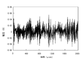
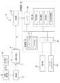
例えば、図1にて示すように、診断対象の鉛蓄電池Bについて、超音波発振子3を鉛蓄電池Bの外壁の一方の側面に取り付け、他方の外壁の他方の側面に超音波受信子4を取り付けておく。そして、超音波発振子3から複数の周波数成分を持つ超音波を電池B内に印加し、電池内の電極Eに対して垂直に透過しつつ電池外壁に達する超音波を超音波受信子4で受信する。
For example, as shown in FIG. 1, for a lead storage battery B to be diagnosed, an
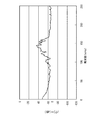
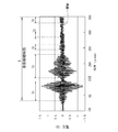
これにより、超音波受信子4からは、例えば、図2に示すような受信信号Srが出力される。図3は、超音波受信子4より出力された図2の受信信号Srをフーリエ変換して、受信信号Srのパワースペクトルデータ(各周波数成分ごとのパワーの分布)を算出したものである。
Thereby, for example, a reception signal Sr as shown in FIG. 2 is output from the
かくして、得られる受信信号Srのパワースペクトルデータは、電池の劣化と強い相関を示す。具体的には、図3のデータは劣化した状態にある鉛蓄電池(対定格容量比が小さくなった鉛蓄電池)のパワースペクトルデータ、図4のデータは劣化してない鉛蓄電池(対定格容量比が100%にほぼ近い鉛蓄電池)のパワースペクトルデータである。 Thus, the power spectrum data of the received signal Sr obtained shows a strong correlation with the deterioration of the battery. Specifically, the data of FIG. 3 is the power spectrum data of a lead storage battery in a deteriorated state (lead storage battery with a reduced rated capacity ratio), and the data of FIG. 4 is an undegraded lead storage battery (to rated capacity ratio). Is a power spectrum data of a lead storage battery that is nearly 100%.
図3と図4を比較して明らかなように、各スペクトルのパワー(強さ)は、鉛蓄電池Bの劣化が進むにつれて増大傾向となる。このような傾向を示すのは、電池の劣化が進むと、電池内部では電極Eの崩落が起きたり、活物質の一部が剥離した状態になることから、超音波が電池内を透過しやすくなるためと考えられるからである。 As is clear from comparison between FIG. 3 and FIG. 4, the power (strength) of each spectrum tends to increase as the deterioration of the lead storage battery B proceeds. This tendency is indicated by the fact that as the battery deteriorates, the electrode E collapses inside the battery or a part of the active material is peeled off, so that ultrasonic waves easily pass through the battery. Because it is considered to be.
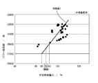
そして、対定格容量比の異なる同種の鉛蓄電池Bについて、パワースペクトルデータを計測する試験をそれぞれ行ったところ、対定格容量比と超音波のパワー総和値(図5にてグレーで示す領域の面積)は、ほぼ比例関係があり、図6に示すような相関線2(関係式2)で表せることが解っている。 And about the same kind lead acid battery B from which a to-rated capacity ratio differs, when the test which measures power spectrum data was each performed, the to-rated capacity ratio and the ultrasonic power total value (area of the area | region shown in gray in FIG. 5) ) Has a substantially proportional relationship and can be expressed by a correlation line 2 (relational expression 2) as shown in FIG.
以上のことから、診断したい鉛蓄電池に上記した超音波検出動作を行い、得られる超音波のパワースペクトルデータからパワー総和値を求めてやれば、求めたパワー総和値と図6の相関線2とに基づいて、鉛蓄電池Bの対定格容量比を算出でき、もって、劣化を診断することが可能となる。例えば、閾値が対定格容量比90%に設定されている場合において、診断対象の鉛蓄電池Bに係る超音波のパワー総和値が「−29000dB」であったとすると、図6にて示すように、対定格容量比は「約93%」にとなり、閾値である「90%」を上回るから、このときは、「劣化していない」と判定される。また、診断対象の鉛蓄電池に係る超音波のパワー総和値が「−27000dB」であったとすると、図6にて示すように、対定格容量比は「約86%」になり、閾値である「90%」を下回るから、このときは、「劣化している」と判定される。 From the above, if the ultrasonic detection operation described above is performed on the lead storage battery to be diagnosed, and the power sum value is obtained from the power spectrum data of the obtained ultrasound, the obtained power sum value and the correlation line 2 in FIG. Based on the above, it is possible to calculate the ratio of the lead storage battery B to the rated capacity, thereby diagnosing deterioration. For example, in the case where the threshold value is set to the rated capacity ratio of 90%, if the ultrasonic power total value related to the lead storage battery B to be diagnosed is “−29000 dB”, as shown in FIG. The rated capacity ratio is “about 93%”, which exceeds the threshold value “90%”. At this time, it is determined that “deterioration has not occurred”. Also, assuming that the total power value of the ultrasonic wave related to the lead storage battery to be diagnosed is “−27000 dB”, as shown in FIG. 6, the rated capacity ratio is “about 86%”, which is the threshold value “ Since it is less than “90%”, it is determined that “deteriorated” at this time.
さて、一般に、超音波受信子4により計測可能な超音波は、音圧レベルに一定の幅があり、受信時の音圧レベルが高すぎると出力される受信信号が飽和した状態となる。また受信時の音圧レベルが低すぎると超音波それ自体を受信出来ず、この場合も計測できない。
Now, in general, ultrasonic waves that can be measured by the
その一方、電池に対する超音波の通り易さは、電池の容量(定格容量の大きさ)により異なる。小容量の電池では、電池サイズそのものが小さく、超音波の透過距離(発振子3から受信子4までの距離)Lが短くなるから、超音波は当然通り易くなる。また、大容量の電池では、電池サイズそのものが大きく透過距離Lが長くなるから、超音波は当然通り難くなる。
On the other hand, the ease with which ultrasonic waves pass through the battery varies depending on the capacity of the battery (the size of the rated capacity). In a small-capacity battery, the battery size itself is small, and the ultrasonic transmission distance (distance from the
そのため、発振時における超音波の音圧レベルを一定値に固定しておくと、電池によっては、受信時の音圧レベルが高くなり過ぎて受信信号が飽和した状態となったり、またそれとは反対に受信時の音圧レベルが低くなり過ぎて受信できない恐れがある。 Therefore, if the sound pressure level of the ultrasonic wave at the time of oscillation is fixed to a constant value, depending on the battery, the sound pressure level at the time of reception becomes too high and the received signal becomes saturated, or vice versa. However, the sound pressure level at the time of reception may be too low to be received.
この点を鑑み、本実施形態のものは、超音波発振子3にて発振する超音波の音圧レベルを、電池の容量(電池に対する超音波の通り易さ)に応じて切り換えるようにした。具体的には、受信時の音圧レベルが高いことが予想される小容量の電池に対しては、発振時における超音波の音圧レベルを予め低いレベルに設定することとし、また、受信時の音圧レベルが低いことが予想される大容量の電池に対しては、発振時における超音波の音圧レベルを予め高いレベルに設定することとした。
In view of this point, in the present embodiment, the sound pressure level of the ultrasonic wave oscillated by the
このようにすることで、電池に対する超音波の通り易さが異なっても、受信時における超音波の音圧レベルは測定に適した一定の音圧レベルになる結果、一台の装置で、超音波の通り易さの異なる鉛蓄電池の劣化を診断することが可能となる。 In this way, the ultrasonic sound pressure level at the time of reception becomes a constant sound pressure level suitable for measurement, even if the ultrasonic wave passing through the battery is different. It becomes possible to diagnose the deterioration of lead acid batteries having different easiness of passing sound waves.
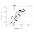
また、各容量の鉛蓄電池Bに対して超音波検出動作を行っておき、先に説明した対定格容量比と超音波のパワー総和値との関係を示す相関線をそれぞれ求めておくことが好ましい。そして、劣化の診断過程において、対定格容量比を算出する場合には、その容量の鉛蓄電池Bに対応した相関線を用いることが好ましい。これは、図6〜図8にて示すように、電池の容量が異なると、それに対応して相関線の傾き、切片の値が変わるからである。尚、上記相関線を求めるために行う超音波検出動作においても、発振時の超音波の音圧レベルを、超音波の通り易さに応じて予め設定した音圧レベルにて行うことが、無論必要である。 Moreover, it is preferable to perform an ultrasonic detection operation for each capacity of the lead storage battery B and to obtain a correlation line indicating the relationship between the above-described rated capacity ratio and the total power value of the ultrasonic wave. . When calculating the ratio of the rated capacity to the rated capacity in the deterioration diagnosis process, it is preferable to use a correlation line corresponding to the lead storage battery B having the capacity. This is because, as shown in FIGS. 6 to 8, when the battery capacity is different, the slope of the correlation line and the value of the intercept change correspondingly. In the ultrasonic detection operation performed to obtain the correlation line, it is of course possible to perform the ultrasonic sound pressure level at the time of oscillation at a sound pressure level set in advance according to the ease of passing the ultrasonic wave. is necessary.
2.劣化診断装置の構成
次に、上記した劣化診断方法を実現させる劣化診断装置10の説明を行う。尚、ここでは、診断対象として、小容量の鉛蓄電池、中容量の鉛蓄電池、大容量の鉛蓄電池の3タイプの電池があり、これら各電池に対応した3パターンの相関線(図6〜図8)を数式で置き換えた3パターンの関係式1〜関係式3をデータとして持つデータテーブル(図9に示す)が、後述する記憶部70に予め記憶されているものとする。
2. Configuration of Deterioration Diagnosis Device Next, the
図10に示すように、本劣化診断装置10は、大まかに言うと、超音波発振子3と、超音波受信子4と、処理装置50とを主体に構成されている。
As shown in FIG. 10, the
超音波発振子3としては、例えば圧電素子が使用出来る。係る超音波発振子3は増幅器(パワーアンプ)41を介して音源発生器20に接続されている。本実施形態の音源発生器20は、図11にて示されるように、42段M系列のシフトレジスタ21と、ローパスフィルタ23と、プリアンプ25と、から構成されている。
As the
42段M系列のシフトレジスタ21は擬似バイナリ信号を生成する機能を担うものである。ローパスフィルタ23はカットオフ周波数が500kHzに設定してあり、それを超える帯域の信号を抑圧する機能を担う。また、プリアンプ25は、2つのアンプAとアッテネータ27と、から構成されている。
The 42-stage M-
そして、42段M系列のシフトレジスタ21にて生成された擬似バイナリ信号は、ローパスフィルタ23を通されることにより、振幅が正規分布し周波数特性が平坦(1kHzから500kHz)なホワイトノイズ波(電気信号)となる。そして、このホワイトノイズ波(以下、単にノイズ波)はその後、プリアンプ25にて、所定の電圧レベルにまで増幅される。
Then, the pseudo binary signal generated by the 42-stage M-
プリアンプ25により所定の電圧レベルに増幅されたノイズ波(電気信号)は、増幅器41を通して再び増幅され、超音波発振子3に入力される。これにより、超音波発振子3が駆動され、500kHzまでの周波数成分を含む超音波が発振される。
The noise wave (electric signal) amplified to a predetermined voltage level by the
また、図10に示す切り換えスイッチ(手動操作式の回転操作子)30は、超音波発振子3から発振される超音波の音圧レベルを切り換えるものである。すなわち、この切り換えスイッチ30を操作すると、プリアンプ25を構成するアッテネータ27に対して切換信号Stが出力され、アッテネータ27にて信号の減衰量が自動的に切り換えられる構成となっている。
A changeover switch (manually operated rotary operator) 30 shown in FIG. 10 switches the sound pressure level of the ultrasonic wave oscillated from the
これにより、超音波発振子3に送られるノイズ波(電気信号)の電圧レベル、引いては超音波発振子3から発振される超音波の音圧レベルが切り換わることとなる。
As a result, the voltage level of the noise wave (electrical signal) sent to the
既に説明してあるように、本実施形態の劣化診断装置10は診断対象として小容量の鉛蓄電池、中容量の鉛蓄電池、大容量の鉛蓄電池の3タイプを想定しており、アッテネータ27による信号の減衰量(1/2、1/4、1/20)、引いては超音波の音圧レベルが3段階(音圧レベル1〜音圧レベル3)に切り換えられるようになっている。
As already described, the
超音波受信子4は例えば、圧電素子よりなり、超音波を受信して、その超音波の波長、振幅、周波数に応じた受信信号Srを出力する機能を担う。この超音波受信子4の出力側は増幅器45を介して、処理装置50に設けられるA/D変換器60に接続されている。これにより、超音波受信子4から出力された超音波の受信信号Srは増幅器45で増幅された後、A/D変換器60にてディジタル信号に変換される構成となっている。
The
処理装置50は記憶部70、CPU80、入出力部90などを備える。記憶部70には、CPU80が各種演算処理を行う際に実行するプログラム、データテーブルDTが記憶されている。データテーブルDTについては既に説明した通りであり、図9にて示すように、電池のタイプごとに、関係式と音圧レベルがそれぞれ対応付けされた状態で記憶されている。
The
CPU80は処理装置50の全体を制御するものであって、大別すると、以下の4つの機能を担っている。
(1)算出機能
(2)読出機能
(3)診断機能
(4)表示制御機能
The
(1) Calculation function (2) Reading function (3) Diagnosis function (4) Display control function
算出機能というのは、ディジタル値に変換された受信信号Srをフーリエ変換(FFT)して超音波のパワースペクトルデータを求め、更に、求めたパワースペクトルデータから超音波のパワー総和値(パワースペクトルの積分値)を算出する機能である。尚、このCPU80が担う算出機能により本発明の算出手段の果たす処理機能、すなわち「前記超音波受信子から出力される前記超音波の受信信号をデータ処理(ここではFFT、積分演算など)して当該受信信号の特徴量(ここでは、パワー総和値)を算出する」が実現されている。
The calculation function is that the received signal Sr converted into a digital value is subjected to Fourier transform (FFT) to obtain ultrasonic power spectrum data, and the ultrasonic power total value (power spectrum value) is calculated from the obtained power spectrum data. This is a function for calculating an integral value. Incidentally, the processing function performed by the calculation means of the present invention by the calculation function performed by the
読出機能というのは、データテーブルDTにアクセスして、診断対象となる鉛蓄電池Bのタイプに対応した関係式を読み出す機能である。尚、このCPU80が担う読出機能により、本発明の読出手段の果たす処理機能が実現されている。
The read function is a function for accessing the data table DT and reading a relational expression corresponding to the type of the lead storage battery B to be diagnosed. The processing function performed by the reading means of the present invention is realized by the reading function performed by the
診断機能というのは、算出した超音波のパワー総和値と読み出した関係式とに基づいて、診断対象となる鉛蓄電池Bの対定格容量比を算出すると共に、これを閾値として設定された対定格容量比と大小比較することにより、診断対象となる鉛蓄電池が劣化しているか、どうか診断する機能である。尚、このCPU80が担う診断機能により、本発明の診断手段の果たす処理機能が実現されている。
The diagnostic function calculates the relative capacity ratio of the lead storage battery B to be diagnosed on the basis of the calculated ultrasonic power total value and the read relational expression, and the relative rating set as a threshold value. This is a function for diagnosing whether or not the lead storage battery to be diagnosed has deteriorated by comparing with the capacity ratio. The processing function performed by the diagnostic means of the present invention is realized by the diagnostic function performed by the
表示制御機能というのは、入出力部90に接続された表示部95の表示内容を制御する機能である。本実施形態のものは、CPU80の制御下のもと、測定開始時には必要となる案内表示が、測定終了後には診断結果(劣化の有無)と共に対定格容量比が表示部95に表示される構成となっている。
The display control function is a function for controlling the display content of the
また、入出力部90にはユーザインターフェース93が電気的に接続されている。このユーザインターフェース93は、キーボード、マウスなどであり、これを用いて、診断対象となる鉛蓄電池Bのタイプ、閾値など診断に必要な条件を、入力操作できる。
A
3.診断動作
次に上記の如く構成された劣化診断装置10を用いて行われる具体的な診断動作について説明を行う。尚、ここでは超音波発振子3及び超音波受信子4を、診断対象となる鉛蓄電池Bに対して図1の状態に取り付けてあるものとして説明を行う。
3. Diagnosis Operation Next, a specific diagnosis operation performed using the
診断を開始するべく劣化診断装置10の電源を投入すると、装置が起動状態になる。すると、CPU80による表示制御がなされ、表示部95の表示画面中に、以下の表示がなされる。
When the
(a)診断対象となる電池のタイプ(小容量、中容量、大容量)の選択を促す表示
(b)閾値の入力を促す表示
(A) Display for prompting selection of battery type (small capacity, medium capacity, large capacity) to be diagnosed (b) Display for prompting input of threshold value
ここでは、ユーザにより、電池のタイプとして「中容量」が選択され、また閾値が「対定格容量比90%」に設定されたものとして説明を進める。尚、これら電池タイプの選択、閾値の設定は、いずれもユーザインターフェース93によって行うことが出来る。
Here, the description will be made assuming that “medium capacity” is selected as the battery type by the user, and the threshold is set to “ratio to rated
電池タイプの選択、閾値の設定が行われると、CPU80は、入力された閾値のデータを記憶部70に記憶させると共に、データテーブルDTにアクセスして、選択された電池タイプに対応する「音圧レベル」を読み出す処理を行う。これにより「中容量」に対応する「音圧レベル2」が読み出されることとなる。
When the battery type is selected and the threshold value is set, the
そして、診断対象の鉛蓄電池Bに対応する「音圧レベル」が読み出されると、CPU80は、ユーザに「音圧レベル」の切り換えを行わせるべく、表示部95の表示画面中に「切り換えスイッチ30を操作して超音波の音圧レベルを音圧レベル2に切り換えて下さい」などの案内表示を行う。
When the “sound pressure level” corresponding to the lead storage battery B to be diagnosed is read, the
上記の表示がされたら、切り換えスイッチ30を操作して「音圧レベル」を「2」に合わせてやればよく、これを行うと、切換信号Stがアッテネータ27に入力される。すると、アッテネータ27にて、超音波発振子3から発振される超音波の音圧レベルが「音圧レベル2」になるように、信号の減衰量が自動的に切り換えられる(切り換えステップ)。
When the above display is displayed, the
そして、音圧レベルの切り換え操作が完了したら、あとは、表示部95の表示画面中に表示される開始スイッチを操作してやればよく、これを行うと、音源発生器20が作動する。これにより、超音波発振子3から「音圧レベル2」の超音波が発振され診断対象となる鉛蓄電池Bに印加される(印加ステップ)。
When the sound pressure level switching operation is completed, the start switch displayed on the display screen of the
鉛蓄電池Bに印加された超音波は電池内を透過し、反対側の外壁に取り付けた超音波受信子4にて受信される。すると、超音波受信子4から、受信した超音波の波長、振幅、周波数に応じた受信信号Srが出力される(受信ステップ)。
The ultrasonic wave applied to the lead storage battery B passes through the battery and is received by the
出力された超音波の受信信号Srは増幅器45にて増幅された後、処理装置50内に取り込まれる。そして、処理装置50に設けられるA/D変換器60によりディジタル信号に変換される。その後、処理装置50内では、CPU80により、取り込まれた受信信号Srをフーリエ変換(FFT)して超音波のパワースペクトルデータを求め、更に、求めたパワースペクトルデータから超音波のパワー総和値が算出される(算出ステップ)。
The output ultrasonic reception signal Sr is amplified by the
超音波のパワー総和値が算出されると、続いてCPU80は、データテーブルDTにアクセスして、診断対象となる鉛蓄電池Bのタイプに対応した関係式を読み出す処理を行う。ここでは、診断対象は「中容量」の鉛蓄電池Bであるから「関係式2」がデータテーブルDTから読み出されることとなる(読出ステップ)。
When the ultrasonic power total value is calculated, the
そして、関係式が読み出されると、CPU80は、算出した超音波のパワー総和値と読み出した関係式とに基づいて、診断対象となる鉛蓄電池Bの対定格容量比を算出すると共に、これを閾値として設定された対定格容量比と大小比較することにより、診断対象となる鉛蓄電池Bが劣化しているか、どうか診断する(診断ステップ)。ここでは、診断対象となる鉛蓄電池Bの対定格容量比が「約93%」であり、閾値である「90%」を上回っており、「劣化していない」と判定されたものとする。
Then, when the relational expression is read, the
かくして、診断対象となる鉛蓄電池Bについて劣化の診断が行われると、CPU80は表示部95の表示画面上に診断結果と共に、算出した対定格容量比を表示する。これにより、表示画面中に「劣化なし」、対定格容量比「93%」と表示されることとなる。
Thus, when the deterioration diagnosis is performed on the lead storage battery B to be diagnosed, the
続いて、タイプの違う鉛蓄電池B、例えば、「小容量」の電池を診断する場合を説明してゆく。この場合も、先に説明した中容量の鉛蓄電池Bの場合と基本的には、同じ要領で作業が進められてゆくことになる。すなわち、まず、表示部95の表示画面中に表示される案内に従って、電池のタイプの選択作業と、それに合わせて閾値の設定が行われる。
Next, a case where a lead storage battery B of a different type, for example, a “small capacity” battery is diagnosed will be described. In this case as well, the work is basically proceeded in the same manner as in the case of the medium capacity lead storage battery B described above. That is, first, according to the guidance displayed on the display screen of the
電池タイプの選択、閾値の設定が行われると、CPU80は、入力された閾値のデータを記憶部70に記憶させると共に、データテーブルDTにアクセスして、入力された電池のタイプに対応する「音圧レベル」を読み出す処理を行う。これにより選択された「小容量」に対応する「音圧レベル1」が読み出されることとなる。
When the battery type is selected and the threshold value is set, the
そして、診断対象の電池タイプに対応する「音圧レベル」が読み出されると、CPU80はユーザに「音圧レベル」の切り換えを行わせるべく、表示部95の表示画面中に「切り換えスイッチ30を操作して超音波の音圧レベルを音圧レベル1に切り換えて下さい」などの案内表示を行う。
When the “sound pressure level” corresponding to the battery type to be diagnosed is read, the
上記の表示がされたら、切り換えスイッチ30を操作して「音圧レベル」を「1」に合わせてやればよく、これを行うと、切換信号Stがアッテネータ27に入力される。すると、アッテネータ27にて、超音波発振子3から発振される超音波の音圧レベルが「音圧レベル1」になるように、信号の減衰量が自動的に切り換えられる(切り換えステップ)。
When the above display is made, the
そして、音圧レベルの切り換え操作が完了したら、あとは、表示部95の表示画面中に表示される開始スイッチを操作してやればよく、これを行うと、音源発生器20が作動する。これにより、超音波発振子3から「音圧レベル1」の超音波が発振され診断対象の鉛蓄電池Bに印加される(印加ステップ)。
When the sound pressure level switching operation is completed, the start switch displayed on the display screen of the
鉛蓄電池Bに印加された超音波は電池内を透過し、反対側の外壁に取り付けた超音波受信子4にて受信される。すると、超音波受信子4から、受信した超音波の波長、振幅、周波数に応じた受信信号Srが出力される(受信ステップ)。
The ultrasonic wave applied to the lead storage battery B passes through the battery and is received by the
出力された超音波の受信信号Srは増幅器45にて増幅された後、A/D変換器60によりディジタル信号に変換され、処理装置50に取り込まれる。その後、処理装置50内では、CPU80により、取り込まれた受信信号Srをフーリエ変換(FFT)して超音波のパワースペクトルデータを求め、更に、求めたパワースペクトルデータから超音波のパワー総和値が算出される(算出ステップ)。
The output ultrasonic reception signal Sr is amplified by the
超音波のパワー総和値が算出されると、続いてCPU80は、データテーブルDTにアクセスして、診断対象の鉛蓄電池の電池タイプに対応した関係式を読み出す処理を行う。ここでは、診断対象の鉛蓄電池の電池タイプは「小容量」であるから、「関係式1」がデータテーブルDTから読み出されることとなる(読出ステップ)。
When the ultrasonic power sum value is calculated, the
そして、関係式1が読み出されると、CPU80は、算出した超音波のパワー総和値と読み出した関係式1とに基づいて診断対象の鉛蓄電池Bの対定格容量比を算出すると共に、これを閾値として設定された対定格容量比と大小比較することにより、診断対象の鉛蓄電池Bが劣化しているか、どうか診断する(診断ステップ)。
When the
かくして、診断対象の鉛蓄電池Bについて劣化の診断が行われると、CPU80は表示部95の表示画面上に診断結果と共に、算出した対定格容量比を表示する。
Thus, when the deterioration diagnosis is performed on the lead storage battery B to be diagnosed, the
また、「大容量」の電池について劣化を診断する場合も「中容量」、「小容量」の電池について劣化を診断する場合と同様に、その電池のタイプに対応する音圧レベル、すなわち「音圧レベル3」の超音波が超音波発振子3から発振され、これが診断対象の鉛蓄電池Bに印加される。
Similarly, when diagnosing deterioration for a “large capacity” battery, the sound pressure level corresponding to the type of battery, that is, “sound” is the same as when diagnosing deterioration for “medium capacity” and “small capacity” batteries. The ultrasonic wave of “
そして、データテーブルDTから、「大容量」に対応する「関係式3」を読み出され、読み出された「関係式3」と超音波の受信信号Srより算出したパワー総和値とに基づいて、診断対象の鉛蓄電池Bの対定格容量比が算出され、その後、診断対象の鉛蓄電池Bが劣化しているか、どうか診断される。
Then, the “
以上説明したように、本実施形態では、超音波発振子3から発振される超音波の音圧レベルが、診断対象の鉛蓄電池Bに対する超音波の通り易さに応じて切り換えられる。これにより、電池に対する超音波の通り易さが異なっても、受信時における超音波の音圧レベルは測定に適した一定の音圧レベルになる結果、一台の装置で、超音波の通り易さの異なる鉛蓄電池の劣化を診断することが可能となる。
As described above, in the present embodiment, the sound pressure level of the ultrasonic wave oscillated from the
また、本実施形態では、各電池のタイプ(超音波の通り易さ)ごとに関係式を求めたデータテーブルDTを設けてあり、鉛蓄電池Bの劣化を診断するときには、データテーブルDTの中からその電池のタイプに対応した関係式が読み出され、それに基づいて、電池の対定格容量比が算出されるようになっている。そのため、対定格容量比を正確に求めることが可能となり、劣化の有無について、信頼性の高い診断結果を下すことが可能となる。 Moreover, in this embodiment, the data table DT which calculated | required the relational expression for every battery type (easiness of passage of an ultrasonic wave) is provided, and when diagnosing deterioration of the lead storage battery B, it is from the data table DT. A relational expression corresponding to the battery type is read out, and based on the relational expression, the battery to rated capacity ratio is calculated. For this reason, it is possible to accurately determine the ratio of the rated capacity, and it is possible to obtain a highly reliable diagnosis result regarding the presence or absence of deterioration.
<実施形態2>
次に、本発明の実施形態2を図12ないし図14によって説明する。
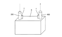
実施形態1では、超音波の受信信号Srから特徴量としてパワー総和値を算出した。実施形態2では、超音波の受信信号Srから特徴量として受信継続時間を算出するようにしている。具体的に説明すると、この場合には、図12に示すように、鉛蓄電池Bの上面の一方の電極端子Tの近傍に超音波発振子300を取り付け、図13に示すような電気信号(例えば150kHz)を超音波発振子300に入力して、所定時間幅(例えば50μ秒)の超音波を発振させ、鉛蓄電池B内に印加する。
<Embodiment 2>
Next, a second embodiment of the present invention will be described with reference to FIGS.
In the first embodiment, the power sum value is calculated as a feature amount from the ultrasonic reception signal Sr. In the second embodiment, the reception duration time is calculated as a feature amount from the ultrasonic reception signal Sr. More specifically, in this case, as shown in FIG. 12, an
一方、超音波受信子400は、電池B内を伝播した超音波を検出するために、鉛蓄電池Bの上面の他方の電極端子Tまたはその近傍に接触して取り付けておく。すると、電池内を伝播する超音波を受信した超音波受信子400から、図14に示すような波形の受信信号Srが出力される。
On the other hand, the
そして、出力された受信信号Srから、電圧レベルが閾値を超える時間、すなわち受信継続時間を算出する(図14では時間t)。係る受信継続時間は、電池の劣化により電極Eの崩落や活物質の剥離が起きると、超音波の伝達経路が短くなることから、時間短縮するものと考えられる。よって、係る受信継続時間を、定格容量のそれと比較してやれば、実施形態1の場合と同様に、電池の劣化を診断することが出来る。尚、受信継続時間はtにかえて、t1〜t5の総和とすることも出来る。 Then, a time during which the voltage level exceeds the threshold, that is, a reception duration time is calculated from the output reception signal Sr (time t in FIG. 14). It is considered that the reception duration is shortened because the ultrasonic transmission path is shortened when the electrode E collapses or the active material peels due to deterioration of the battery. Therefore, if the reception duration is compared with that of the rated capacity, it is possible to diagnose the deterioration of the battery as in the case of the first embodiment. Note that the reception continuation time may be the sum of t1 to t5 instead of t.
<他の実施形態>
本発明は上記記述及び図面によって説明した実施形態に限定されるものではなく、例えば次のような実施形態も本発明の技術的範囲に含まれる。
<Other embodiments>
The present invention is not limited to the embodiments described with reference to the above description and drawings. For example, the following embodiments are also included in the technical scope of the present invention.
(1)実施形態1では、電池を透過する超音波の通り易さが異なる例として、容量(定格容量)の相違を例にとったが、電池の内部構造、活物質の相違などでも、超音波の通り易さは変わる。この点を鑑み、発振時の音圧レベルの切り換えパターンを相当数用意しておけば、鉛蓄電池のほか、ニッケル水素電池、リチウム電池、ニッケルカドニウム電池などの各種二次電池を一台の劣化診断装置により診断することが可能となる。 (1) In the first embodiment, the difference in capacity (rated capacity) is taken as an example in which the ease of passing ultrasonic waves through the battery is different. However, even if the internal structure of the battery and the difference in active material are different, The ease of passing sound waves changes. In view of this point, if a considerable number of switching patterns of sound pressure level during oscillation are prepared, in addition to lead-acid batteries, various secondary batteries such as nickel metal hydride batteries, lithium batteries, and nickel cadmium batteries can be diagnosed as a single unit. Diagnosis is possible with the device.
(2)実施形態1では、超音波発振子3より発振される超音波の音圧レベルを、音源発生器20に設けたアッテネータ27により切り換える構成をとったが、例えば、増幅器41にてゲイン(信号の増幅率)を切り換えることにより、音圧レベルを切り換える構成とすることも可能である。また、実施形態1では音圧レベルを手動で切り換える方式をとったが、電池タイプに応じて自動で切り換える構成とすることも可能である。
(2) In the first embodiment, the sound pressure level of the ultrasonic wave oscillated from the
(3)実施形態1では、データテーブルDTに対して各電池のタイプごとに関係式を記憶させておく構成をとった。そして、データテーブルDTの中から診断対象となる二次電池に対応する関係式を読み出すと共に、読み出した関係式と診断対象となる二次電池に係る超音波のパワー総和値とに基づいて二次電池の対定格容量比を求め、その結果から二次電池の劣化を診断した。劣化診断は、必ずしも関係式に基づいて対定格容量比を算出する方法に限られるものではなく、以下の方法であってもよい。例えば、データテーブルDTに対して各電池のタイプごとに定格容量二次電池に係る超音波の受信信号Srのパワー総和値を記憶されておく構成とする。そして、データテーブルDTの中から診断対象となる二次電池に対応する定格容量二次電池のパワー総和値を読み出し、読み出したパワー総和値と診断対象となる二次電池に係る超音波のパワー総和値を大小比較することにより、二次電池の劣化を診断(読み出したパワー総和値に対して診断対象側のパワー総和値が上回っている場合に、劣化と判定するなど)してもよい。 (3) In the first embodiment, a relational expression is stored for each battery type in the data table DT. Then, a relational expression corresponding to the secondary battery to be diagnosed is read out from the data table DT, and the secondary expression is based on the read relational expression and the total power value of the ultrasonic waves related to the secondary battery to be diagnosed. The battery-to-rated capacity ratio was determined, and the secondary battery deterioration was diagnosed from the result. The deterioration diagnosis is not necessarily limited to the method of calculating the ratio of rated capacity based on the relational expression, and may be the following method. For example, the power total value of the ultrasonic reception signal Sr related to the rated capacity secondary battery is stored for each battery type in the data table DT. Then, the power sum value of the rated capacity secondary battery corresponding to the secondary battery to be diagnosed is read from the data table DT, and the read power sum value and the ultrasonic power sum of the secondary battery to be diagnosed are read. By comparing the values, the deterioration of the secondary battery may be diagnosed (determination is made when the power sum value on the diagnosis target side exceeds the read power sum value).
3…超音波発振子
4…超音波受信子
20…音源発生器
27…アッテネータ(本発明の「切換手段」に相当)
30…切り換えスイッチ(本発明の「切換手段」に相当)
50…処理装置
70…記憶部
80…CPU(本発明の「算出手段、読出手段、診断手段」に相当)
93…ユーザインターフェース
95…表示部
300…超音波発振子
400…超音波受信子
DESCRIPTION OF
30 ... changeover switch (corresponding to "switching means" of the present invention)
DESCRIPTION OF
93 ...
Claims (6)
診断対象となる二次電池の外側に取り付けた超音波発振子より発振される超音波の音圧レベルを、その二次電池に対する超音波の通り易さに応じて予め設定された前記音圧レベルに切り換える切り換えステップと、
切り換えた音圧レベルにて超音波を発振させ二次電池に印加させる印加ステップと、
診断対象となる二次電池の外側に取り付けた超音波受信子によって、前記二次電池内を進み電池外壁に達する超音波を受信する受信ステップと、
前記超音波受信子から出力される前記超音波の受信信号をデータ処理して当該受信信号の特徴量を算出する算出ステップと、
前記データテーブルから、診断対象となる二次電池と同じタイプの定格容量二次電池に係る超音波の受信信号の特徴量を択一的に読み出す読出ステップと、
読み出した定格容量二次電池に係る超音波の受信信号の特徴量と、前記算出ステップにて算出した二次電池に係る超音波の受信信号の特徴量とを比較することにより、診断対象となる二次電池の劣化を診断する診断ステップと、を有する二次電池の劣化診断方法。 An ultrasonic detection operation is performed in which ultrasonic waves having a preset sound pressure level are applied to the secondary battery according to the ease of passing ultrasonic waves, and ultrasonic waves that travel through the secondary battery and reach the battery outer wall are received. , Using a data table having each feature amount calculated as data by processing each received signal obtained for each rated capacity secondary battery with different ease of passing ultrasonic waves, A deterioration diagnosis method for diagnosing deterioration,
The sound pressure level of the ultrasonic wave oscillated from the ultrasonic oscillator attached to the outside of the secondary battery to be diagnosed is set in advance according to the ease of passing the ultrasonic wave to the secondary battery. A switching step to switch to
An application step of oscillating ultrasonic waves at the switched sound pressure level and applying them to the secondary battery;
A reception step of receiving ultrasonic waves that travel through the secondary battery and reach the outer wall of the battery by an ultrasonic receiver attached to the outside of the secondary battery to be diagnosed;
A calculation step of performing data processing on the reception signal of the ultrasonic wave output from the ultrasonic wave receiver and calculating a feature amount of the reception signal;
From the data table, a readout step for selectively reading out the feature quantity of the received signal of the ultrasonic wave related to the rated capacity secondary battery of the same type as the secondary battery to be diagnosed;
The feature quantity of the ultrasonic reception signal related to the read rated capacity secondary battery is compared with the feature quantity of the ultrasonic reception signal related to the secondary battery calculated in the calculation step, thereby making a diagnosis target. A method for diagnosing deterioration of the secondary battery, and a method for diagnosing deterioration of the secondary battery.
前記データテーブルに、前記特徴量の大きさと対定格容量比の対応関係を示す関係式を、超音波の通り易さが異なる各二次電池のそれぞれについて記憶させておき、
前記読出ステップにて、前記データテーブルに記憶された各関係式の中から、診断対象となる二次電池に対応する関係式を読み出し、
前記診断ステップにて、診断対象となる二次電池に係る超音波の受信信号の特徴量と読み出した前記関係式とに基づいて診断対象となる二次電池の対定格容量比を求め、求めた対定格容量比から診断対象となる二次電池の劣化を診断することを特徴とする。 A deterioration diagnosis method for a secondary battery according to claim 1,
In the data table, a relational expression indicating the correspondence between the size of the feature amount and the rated capacity ratio is stored for each of the secondary batteries having different ease of passing ultrasonic waves,
In the reading step, the relational expression corresponding to the secondary battery to be diagnosed is read out from each relational expression stored in the data table,
In the diagnosis step, the ratio of the capacity of the secondary battery to be diagnosed is obtained based on the feature quantity of the received signal of the ultrasonic wave related to the secondary battery to be diagnosed and the read relational expression, It is characterized by diagnosing the deterioration of the secondary battery to be diagnosed from the ratio of the rated capacity.
前記超音波発振子と前記超音波受信子とを、診断対象となる二次電池に対して、超音波が電池内の電極に対して垂直に透過するように向かい合わせて配置すると共に、前記超音波発振子から複数の周波数成分を含む超音波を発振して診断対象となる二次電池に印加するものにおいて、
前記超音波の受信信号をフーリエ変換してパワースペクトルデータを求め、更に、求めたパワースペクトルデータから算出される超音波のパワー総和値を前記特徴量とすることを特徴とする。 A method for diagnosing deterioration of a secondary battery according to claim 1 or 2,
The ultrasonic oscillator and the ultrasonic receiver are arranged facing each other so that the ultrasonic wave is transmitted perpendicular to the electrode in the battery with respect to the secondary battery to be diagnosed. In what is applied to a secondary battery to be diagnosed by oscillating ultrasonic waves containing a plurality of frequency components from a sound wave oscillator,
The ultrasonic reception signal is subjected to Fourier transform to obtain power spectrum data, and the ultrasonic power total value calculated from the obtained power spectrum data is used as the feature amount.
診断対象となる二次電池の外側に取り付けられ、超音波を発振して前記二次電池に印加させる超音波発振子と、
前記超音波発振子から発振される超音波の音圧レベルを切り換える切換手段と、
診断対象となる二次電池の外側に取り付けられ、前記二次電池内を進み電池外壁に達する超音波を受信する超音波受信子と、
前記超音波受信子から出力される前記超音波の受信信号をデータ処理して当該受信信号の特徴量を算出する算出手段と、
二次電池に対して超音波の通り易さに応じて予め設定した音圧レベルの超音波を印加し、その二次電池内を進んで電池外壁に達する超音波を受信する超音波検出動作を、超音波の通り易さが異なる各定格容量二次電池に対して行って得た各受信信号をデータ処理して算出した各特徴量をデータとして持つデータテーブルを記憶した記憶部と、
前記記憶部に記憶されたデータテーブルから、診断対象となる二次電池と同じタイプの定格容量二次電池に係る超音波の受信信号の特徴量を択一的に読み出す読出手段と、
読み出した定格容量二次電池に係る超音波の受信信号の特徴量と、前記算出手段にて算出した診断対象となる二次電池に係る超音波の受信信号の特徴量とを比較することにより、診断対象となる二次電池の劣化を診断する診断手段と、を備えた二次電池の劣化診断装置。 A secondary battery deterioration diagnosis device,
An ultrasonic oscillator that is attached to the outside of a secondary battery to be diagnosed and that oscillates and applies an ultrasonic wave to the secondary battery;
Switching means for switching the sound pressure level of the ultrasonic wave oscillated from the ultrasonic oscillator;
An ultrasonic receiver attached to the outside of the secondary battery to be diagnosed and receiving ultrasonic waves that travel through the secondary battery and reach the outer wall of the battery;
Calculating means for processing the ultrasonic reception signal output from the ultrasonic receiver and calculating a feature quantity of the reception signal;
An ultrasonic detection operation is performed in which ultrasonic waves having a preset sound pressure level are applied to the secondary battery according to the ease of passing ultrasonic waves, and ultrasonic waves that travel through the secondary battery and reach the battery outer wall are received. A storage unit storing a data table having each feature amount calculated as data by processing each received signal obtained for each rated capacity secondary battery with different ease of passing ultrasonic waves;
Reading means for selectively reading out the feature quantity of the received signal of the ultrasonic wave related to the rated capacity secondary battery of the same type as the secondary battery to be diagnosed from the data table stored in the storage unit;
By comparing the characteristic amount of the ultrasonic reception signal related to the read rated capacity secondary battery with the characteristic amount of the ultrasonic reception signal related to the secondary battery to be diagnosed calculated by the calculation means, And a diagnostic means for diagnosing degradation of a secondary battery to be diagnosed.
前記データテーブルに、前記特徴量の大きさと対定格容量比の対応関係を示す関係式を、超音波の通り易さが異なる各二次電池のそれぞれについて記憶させておき、
前記読出手段は、前記データテーブルに記憶された各関係式の中から、診断対象となる二次電池に対応する関係式を読み出し、
前記診断手段は、診断対象となる二次電池に係る超音波の受信信号の特徴量と読み出した前記関係式とに基づいて診断対象となる二次電池の対定格容量比を求め、求めた対定格容量比から診断対象となる二次電池の劣化を診断することを特徴とする。 The deterioration diagnosis device according to claim 4,
In the data table, a relational expression indicating the correspondence between the size of the feature amount and the rated capacity ratio is stored for each of the secondary batteries having different ease of passing ultrasonic waves,
The reading means reads a relational expression corresponding to a secondary battery to be diagnosed from among the relational expressions stored in the data table,
The diagnostic means obtains the rated capacity ratio of the secondary battery to be diagnosed based on the feature quantity of the ultrasonic reception signal related to the secondary battery to be diagnosed and the read relational expression, It is characterized by diagnosing the deterioration of the secondary battery to be diagnosed from the rated capacity ratio.
前記超音波発振子と前記超音波受信子とを、診断対象となる二次電池に対して、超音波が電池内の電極に対して垂直に透過するように向かい合わせて配置すると共に、前記超音波発振子から複数の周波数成分を含む超音波を発振して診断対象となる二次電池に印加するものにおいて、
前記超音波の受信信号をフーリエ変換してパワースペクトルデータを求め、更に、求めたパワースペクトルデータから算出される超音波のパワー総和値を前記特徴量とすることを特徴とする。 The deterioration diagnosis apparatus according to claim 4 or 5, wherein
The ultrasonic oscillator and the ultrasonic receiver are arranged facing each other so that the ultrasonic wave is transmitted perpendicular to the electrode in the battery with respect to the secondary battery to be diagnosed. In what is applied to a secondary battery to be diagnosed by oscillating ultrasonic waves containing a plurality of frequency components from a sound wave oscillator,
The ultrasonic reception signal is subjected to Fourier transform to obtain power spectrum data, and the ultrasonic power total value calculated from the obtained power spectrum data is used as the feature amount.
Priority Applications (1)
| Application Number | Priority Date | Filing Date | Title |
|---|---|---|---|
| JP2008272301A JP4709885B2 (en) | 2008-10-22 | 2008-10-22 | Secondary battery deterioration diagnosis method and battery deterioration diagnosis device |
Applications Claiming Priority (1)
| Application Number | Priority Date | Filing Date | Title |
|---|---|---|---|
| JP2008272301A JP4709885B2 (en) | 2008-10-22 | 2008-10-22 | Secondary battery deterioration diagnosis method and battery deterioration diagnosis device |
Publications (2)
| Publication Number | Publication Date |
|---|---|
| JP2010101706A true JP2010101706A (en) | 2010-05-06 |
| JP4709885B2 JP4709885B2 (en) | 2011-06-29 |
Family
ID=42292477
Family Applications (1)
| Application Number | Title | Priority Date | Filing Date |
|---|---|---|---|
| JP2008272301A Expired - Fee Related JP4709885B2 (en) | 2008-10-22 | 2008-10-22 | Secondary battery deterioration diagnosis method and battery deterioration diagnosis device |
Country Status (1)
| Country | Link |
|---|---|
| JP (1) | JP4709885B2 (en) |
Cited By (4)
| Publication number | Priority date | Publication date | Assignee | Title |
|---|---|---|---|---|
| WO2013132907A1 (en) * | 2012-03-08 | 2013-09-12 | 株式会社 日立製作所 | Lithium-ion secondary cell system, method for testing lithium-ion secondary cell, and method for controlling lithium-ion secondary cell |
| WO2013150157A1 (en) | 2012-04-06 | 2013-10-10 | Commissariat à l'énergie atomique et aux énergies alternatives | Battery protected against electric arcs |
| KR20150045594A (en) * | 2013-10-21 | 2015-04-29 | 주식회사 엘지화학 | Method of nondestructive stiffness inspection in battery cell and apparatus thereof |
| JP2018537682A (en) * | 2016-11-21 | 2018-12-20 | ▲華▼中科技大学Huazhong University Of Science And Technology | Method and apparatus for measuring the state of charge and health of a lithium ion battery |
Citations (4)
| Publication number | Priority date | Publication date | Assignee | Title |
|---|---|---|---|---|
| JPS6256809A (en) * | 1985-09-05 | 1987-03-12 | Yuasa Battery Co Ltd | Internal inspecting method for lead battery |
| JPH0658917A (en) * | 1992-08-07 | 1994-03-04 | Hitachi Constr Mach Co Ltd | Ultrasonic inspection method and device therefor |
| JPH076795A (en) * | 1993-06-21 | 1995-01-10 | Nissan Motor Co Ltd | Device for detecting internal condition of battery |
| JP2005291832A (en) * | 2004-03-31 | 2005-10-20 | Chubu Electric Power Co Inc | Method and apparatus for diagnosing deterioration of battery |
-
2008
- 2008-10-22 JP JP2008272301A patent/JP4709885B2/en not_active Expired - Fee Related
Patent Citations (4)
| Publication number | Priority date | Publication date | Assignee | Title |
|---|---|---|---|---|
| JPS6256809A (en) * | 1985-09-05 | 1987-03-12 | Yuasa Battery Co Ltd | Internal inspecting method for lead battery |
| JPH0658917A (en) * | 1992-08-07 | 1994-03-04 | Hitachi Constr Mach Co Ltd | Ultrasonic inspection method and device therefor |
| JPH076795A (en) * | 1993-06-21 | 1995-01-10 | Nissan Motor Co Ltd | Device for detecting internal condition of battery |
| JP2005291832A (en) * | 2004-03-31 | 2005-10-20 | Chubu Electric Power Co Inc | Method and apparatus for diagnosing deterioration of battery |
Cited By (7)
| Publication number | Priority date | Publication date | Assignee | Title |
|---|---|---|---|---|
| WO2013132907A1 (en) * | 2012-03-08 | 2013-09-12 | 株式会社 日立製作所 | Lithium-ion secondary cell system, method for testing lithium-ion secondary cell, and method for controlling lithium-ion secondary cell |
| WO2013150157A1 (en) | 2012-04-06 | 2013-10-10 | Commissariat à l'énergie atomique et aux énergies alternatives | Battery protected against electric arcs |
| FR2989227A1 (en) * | 2012-04-06 | 2013-10-11 | Commissariat Energie Atomique | BATTERY OF ACCUMULATORS PROTECTED AGAINST ELECTRIC ARCS |
| US9791515B2 (en) | 2012-04-06 | 2017-10-17 | Commissariat à l'énergie atomique et aux énergies alternatives | Battery protected against electric arcs |
| KR20150045594A (en) * | 2013-10-21 | 2015-04-29 | 주식회사 엘지화학 | Method of nondestructive stiffness inspection in battery cell and apparatus thereof |
| KR101653689B1 (en) * | 2013-10-21 | 2016-09-02 | 주식회사 엘지화학 | Method of nondestructive stiffness inspection in battery cell and apparatus thereof |
| JP2018537682A (en) * | 2016-11-21 | 2018-12-20 | ▲華▼中科技大学Huazhong University Of Science And Technology | Method and apparatus for measuring the state of charge and health of a lithium ion battery |
Also Published As
| Publication number | Publication date |
|---|---|
| JP4709885B2 (en) | 2011-06-29 |
Similar Documents
| Publication | Publication Date | Title |
|---|---|---|
| JP4709885B2 (en) | Secondary battery deterioration diagnosis method and battery deterioration diagnosis device | |
| JP4592318B2 (en) | Battery degradation diagnosis method and apparatus | |
| JP5993871B2 (en) | Improvements in or related to ultrasonic generators and methods of generating ultrasonic waves | |
| US11391863B2 (en) | Method of free-field broadband calibration of hydrophone sensitivity based on pink noise | |
| US20120017684A1 (en) | Sensor device and method for operating a sensor device | |
| JPS5847026B2 (en) | How to calibrate acoustic radiation transducers | |
| US20100162817A1 (en) | Ultrasonic stress measurement method and device | |
| US11927703B2 (en) | Ultrasound system and method for controlling ultrasound system | |
| US7831413B2 (en) | Sound field measuring method and sound field measuring device | |
| JP2005180927A (en) | Impedance-measuring instrument | |
| Wei et al. | State estimation of lithium-ion batteries based on the initial rise time feature of ultrasonic signals | |
| JPS5826283A (en) | Ultrasonic measuring device with self-diagnosing function | |
| JP4631615B2 (en) | Surface acoustic wave propagation state measuring device, surface acoustic wave propagation state measuring method, environment change measuring device, environment change measuring method, and multi-round surface acoustic wave element | |
| US20190110777A1 (en) | Ultrasound diagnosis apparatus and method of operating the same | |
| JP2008220690A (en) | Ultrasonic diagnostic system | |
| KR101441195B1 (en) | Ultrasonic diagnosis device and signal processing device calculating spectrum, centroid and method for calculating spectrum centroid | |
| KR20190042427A (en) | Ultrasound diagnosis apparatus and operating method for the same | |
| RU2492431C1 (en) | Method of measurement of power of underwater sound projector and device for implementation of method | |
| CN111527759B (en) | Method and apparatus for detecting failure of acoustic sensor | |
| WO2022200241A1 (en) | Method and system for estimating an ageing indicator of a rechargeable electric battery | |
| JP5375339B2 (en) | Spherical surface acoustic wave module | |
| KR20070010443A (en) | Mobile communication terminal with antenna testing function and method of controlling the same | |
| CN117054527A (en) | Device and method for nondestructive testing of lithium battery based on ultrasonic resonance spectrum | |
| JP4666749B2 (en) | Ultrasound bone evaluation device | |
| JP2020078017A (en) | Breaking of wire detection method of microphone |
Legal Events
| Date | Code | Title | Description |
|---|---|---|---|
| A01 | Written decision to grant a patent or to grant a registration (utility model) |
Free format text: JAPANESE INTERMEDIATE CODE: A01 Effective date: 20110315 |
|
| A61 | First payment of annual fees (during grant procedure) |
Free format text: JAPANESE INTERMEDIATE CODE: A61 Effective date: 20110318 |
|
| LAPS | Cancellation because of no payment of annual fees |