JP2010100340A - Handheld dispenser for personal use - Google Patents
Handheld dispenser for personal use Download PDFInfo
- Publication number
- JP2010100340A JP2010100340A JP2009244731A JP2009244731A JP2010100340A JP 2010100340 A JP2010100340 A JP 2010100340A JP 2009244731 A JP2009244731 A JP 2009244731A JP 2009244731 A JP2009244731 A JP 2009244731A JP 2010100340 A JP2010100340 A JP 2010100340A
- Authority
- JP
- Japan
- Prior art keywords
- liquid
- air
- chamber
- push
- pushable
- Prior art date
- Legal status (The legal status is an assumption and is not a legal conclusion. Google has not performed a legal analysis and makes no representation as to the accuracy of the status listed.)
- Granted
Links
Images


Classifications
-
- B—PERFORMING OPERATIONS; TRANSPORTING
- B65—CONVEYING; PACKING; STORING; HANDLING THIN OR FILAMENTARY MATERIAL
- B65D—CONTAINERS FOR STORAGE OR TRANSPORT OF ARTICLES OR MATERIALS, e.g. BAGS, BARRELS, BOTTLES, BOXES, CANS, CARTONS, CRATES, DRUMS, JARS, TANKS, HOPPERS, FORWARDING CONTAINERS; ACCESSORIES, CLOSURES, OR FITTINGS THEREFOR; PACKAGING ELEMENTS; PACKAGES
- B65D83/00—Containers or packages with special means for dispensing contents
-
- B—PERFORMING OPERATIONS; TRANSPORTING
- B05—SPRAYING OR ATOMISING IN GENERAL; APPLYING FLUENT MATERIALS TO SURFACES, IN GENERAL
- B05B—SPRAYING APPARATUS; ATOMISING APPARATUS; NOZZLES
- B05B11/00—Single-unit hand-held apparatus in which flow of contents is produced by the muscular force of the operator at the moment of use
- B05B11/01—Single-unit hand-held apparatus in which flow of contents is produced by the muscular force of the operator at the moment of use characterised by the means producing the flow
- B05B11/10—Pump arrangements for transferring the contents from the container to a pump chamber by a sucking effect and forcing the contents out through the dispensing nozzle
- B05B11/1028—Pumps having a pumping chamber with a deformable wall
- B05B11/1032—Pumps having a pumping chamber with a deformable wall actuated without substantial movement of the nozzle in the direction of the pressure stroke
-
- A—HUMAN NECESSITIES
- A47—FURNITURE; DOMESTIC ARTICLES OR APPLIANCES; COFFEE MILLS; SPICE MILLS; SUCTION CLEANERS IN GENERAL
- A47K—SANITARY EQUIPMENT NOT OTHERWISE PROVIDED FOR; TOILET ACCESSORIES
- A47K5/00—Holders or dispensers for soap, toothpaste, or the like
- A47K5/06—Dispensers for soap
- A47K5/12—Dispensers for soap for liquid or pasty soap
-
- B—PERFORMING OPERATIONS; TRANSPORTING
- B05—SPRAYING OR ATOMISING IN GENERAL; APPLYING FLUENT MATERIALS TO SURFACES, IN GENERAL
- B05B—SPRAYING APPARATUS; ATOMISING APPARATUS; NOZZLES
- B05B11/00—Single-unit hand-held apparatus in which flow of contents is produced by the muscular force of the operator at the moment of use
- B05B11/01—Single-unit hand-held apparatus in which flow of contents is produced by the muscular force of the operator at the moment of use characterised by the means producing the flow
- B05B11/10—Pump arrangements for transferring the contents from the container to a pump chamber by a sucking effect and forcing the contents out through the dispensing nozzle
- B05B11/1087—Combination of liquid and air pumps
-
- B—PERFORMING OPERATIONS; TRANSPORTING
- B65—CONVEYING; PACKING; STORING; HANDLING THIN OR FILAMENTARY MATERIAL
- B65D—CONTAINERS FOR STORAGE OR TRANSPORT OF ARTICLES OR MATERIALS, e.g. BAGS, BARRELS, BOTTLES, BOXES, CANS, CARTONS, CRATES, DRUMS, JARS, TANKS, HOPPERS, FORWARDING CONTAINERS; ACCESSORIES, CLOSURES, OR FITTINGS THEREFOR; PACKAGING ELEMENTS; PACKAGES
- B65D35/00—Pliable tubular containers adapted to be permanently or temporarily deformed to expel contents, e.g. collapsible tubes for toothpaste or other plastic or semi-liquid material; Holders therefor
- B65D35/24—Pliable tubular containers adapted to be permanently or temporarily deformed to expel contents, e.g. collapsible tubes for toothpaste or other plastic or semi-liquid material; Holders therefor with auxiliary devices
- B65D35/28—Pliable tubular containers adapted to be permanently or temporarily deformed to expel contents, e.g. collapsible tubes for toothpaste or other plastic or semi-liquid material; Holders therefor with auxiliary devices for expelling contents
-
- B—PERFORMING OPERATIONS; TRANSPORTING
- B65—CONVEYING; PACKING; STORING; HANDLING THIN OR FILAMENTARY MATERIAL
- B65D—CONTAINERS FOR STORAGE OR TRANSPORT OF ARTICLES OR MATERIALS, e.g. BAGS, BARRELS, BOTTLES, BOXES, CANS, CARTONS, CRATES, DRUMS, JARS, TANKS, HOPPERS, FORWARDING CONTAINERS; ACCESSORIES, CLOSURES, OR FITTINGS THEREFOR; PACKAGING ELEMENTS; PACKAGES
- B65D35/00—Pliable tubular containers adapted to be permanently or temporarily deformed to expel contents, e.g. collapsible tubes for toothpaste or other plastic or semi-liquid material; Holders therefor
- B65D35/56—Holders for collapsible tubes
-
- B—PERFORMING OPERATIONS; TRANSPORTING
- B05—SPRAYING OR ATOMISING IN GENERAL; APPLYING FLUENT MATERIALS TO SURFACES, IN GENERAL
- B05B—SPRAYING APPARATUS; ATOMISING APPARATUS; NOZZLES
- B05B11/00—Single-unit hand-held apparatus in which flow of contents is produced by the muscular force of the operator at the moment of use
- B05B11/01—Single-unit hand-held apparatus in which flow of contents is produced by the muscular force of the operator at the moment of use characterised by the means producing the flow
- B05B11/02—Membranes or pistons acting on the contents inside the container, e.g. follower pistons
- B05B11/026—Membranes separating the content remaining in the container from the atmospheric air to compensate underpressure inside the container
Abstract
Description
本発明は、一般的には、流体ディスペンサーに関し、より詳細には、流体を空気と混合する、個人用の携帯用流体ディスペンサーに関する。一実施例において、本発明は、発泡可能な液体と空気とを混合する、個人用の携帯用泡ディスペンサーを提供する。特定の好適な実施例において、本発明は、個人用の洗浄用又は消毒用溶液を一回分の量だけ分与するように作動可能な、携帯用の個人用泡ディスペンサーに関する。 The present invention relates generally to fluid dispensers, and more particularly to personal portable fluid dispensers that mix fluid with air. In one embodiment, the present invention provides a personal portable foam dispenser that mixes foamable liquid and air. In certain preferred embodiments, the present invention relates to a portable personal foam dispenser operable to dispense a personal cleaning or disinfecting solution in a single dose.
多様な液体製品用の個人用の携帯用ディスペンサーは、一般的に公知である。これらの流体ディスペンサーには多様な種類がある。いくつかの最も単純な形態ものでは、携帯用ディスペンサーは、内部の液体製品を分与できるように選択的に開くか又は閉めることができるようにされた容器として、提供されている。いくつかの実施例において、これらの容器は、圧力によってへこむことでその内部容積を一時的に減少させ、その内部に保持されている液体製品の一部分を分与する。これらの種類の容器は、手用除菌剤、手用洗浄剤および手用ローションの持ち運び用途において、極めて一般的である。 Personal portable dispensers for a variety of liquid products are generally known. There are various types of these fluid dispensers. In some simplest forms, the portable dispenser is provided as a container that can be selectively opened or closed so that the liquid product inside can be dispensed. In some embodiments, these containers dent by pressure to temporarily reduce their internal volume and dispense a portion of the liquid product held therein. These types of containers are very common in the portable use of hand sanitizers, hand cleaners and hand lotions.
手用除菌剤、手用洗浄剤および手用ローションは、また、容積式ポンプを用いたディスペンサーの使用を通しても、分与される。これらのディスペンサーの一部分は、携帯するのに十分なサイズにされる。これらの携帯用ディスペンサーは、ピストンヘッドを包含し、このピストンヘッドを押して、主容器から液体製品を分与する。これらの携帯用ディスペンサーは、その分与機構の作動により一回分の量の液体製品を分与するという有利な機能を提供する。しかし、(例えば、ディスペンサーをハンドバッグ又は他の手荷物に入れて持ち運んでいるときに)ピストンヘッドが非意図的に押されることで、これらのディスペンサーが誤って作動することは容易にあり得る。そのため、これらのディスペンサーは、より好適には、デッキ上又は流し台のそばでの用途に用いられる。 Hand sanitizers, hand cleaners and hand lotions are also dispensed through the use of dispensers with positive displacement pumps. Some of these dispensers are sized to be portable. These portable dispensers include a piston head that pushes the piston head to dispense a liquid product from the main container. These portable dispensers provide the advantageous function of dispensing a single volume of liquid product by actuation of its dispensing mechanism. However, it is easy for these dispensers to operate accidentally when the piston head is unintentionally pushed (for example, when carrying the dispensers in a handbag or other baggage). Therefore, these dispensers are more preferably used for applications on a deck or near a sink.
携帯用の個人用ディスペンサーは、また、米国特許第6,789,706号および米国公開特許出願第2006/0255068号に記載のような可撓性壁および定量分与能力を有するものとしても提供されている。ポンプは、可撓性壁の容器中の液体製品源と連通し、また出口とも連通する。前記ポンプが作動すると、前記出口から液体製品が押し出され、前記ポンプが解放されると、更に一回分の量の液体製品が前記容器から引き込まれて、その後の作動により分与される。これらは、液体製品を分与する単一構成要素のディスペンサーである。 Portable personal dispensers are also provided as having flexible walls and metered dispensing capabilities as described in US Pat. No. 6,789,706 and US Published Patent Application No. 2006/0255068. ing. The pump communicates with the liquid product source in the flexible wall container and also with the outlet. When the pump is activated, liquid product is pushed out from the outlet, and when the pump is released, a further quantity of liquid product is drawn from the container and dispensed by subsequent operation. These are single component dispensers that dispense liquid products.
近年、多種の液体を泡形態で分与することが一般的になっており、この泡は基本的には、少なくとも2つの成分の混合物(典型的には、発泡可能な液体中全体に分散した気泡)である。そのため、多くの環境において、前記標準的な液体ポンプは、所望の泡を生成するような態様で空気と液体とを混合する手段を必要とする泡生成ポンプに取って代わられている。そのため、特定の実施例において、本発明は、一回分の量の泡製品を分与する能力を有する可撓性壁型ディスペンサーを提供し、これにより、個人使用用の、容易に携帯可能な泡ディスペンサーを提供する。以下の開示から明らかなように、本発明は、泡ディスペンサーに限定されるのではなく、泡を生成するため、又は反応を生成させるなどの他のあらゆる理由において、空気が液体と混合される任意のディスペンサーも包含するものである。 In recent years, it has become common to dispense a variety of liquids in the form of bubbles, which are basically a mixture of at least two components (typically dispersed throughout a foamable liquid). Bubbles). Thus, in many environments, the standard liquid pump has been replaced by a foam generation pump that requires a means to mix air and liquid in a manner that produces the desired foam. Thus, in certain embodiments, the present invention provides a flexible wall-type dispenser that has the ability to dispense a single dose of foam product, thereby providing an easily portable foam for personal use. Provide dispenser. As will be apparent from the disclosure below, the present invention is not limited to a foam dispenser, but any air in which the air is mixed with a liquid for any other reason, such as to produce a foam or to produce a reaction. This dispenser is also included.
本発明は、押し出し式液体容器と、押し出し式液体チャンバと、押し出し式空気チャンバと、混合チャンバとを包含する手持ち型ディスペンサーを提供する。前記液体容器は、液体を保持する容積を限定する。前記押し出し式液体チャンバは、前記液体容器内の前記液体と液体入口弁を通して連通し、また前記混合チャンバと液体出口通路を通して連通する。前記押し出し式液体チャンバは、拡張容積と圧縮容積との間で操作されるようにされる。前記押し出し式空気チャンバは、前記ディスペンサーの外部の空気と空気入口弁を通して連通し、また前記混合ユニットと空気出口通路を通して連通する。前記押し出し式空気チャンバは、拡張容積と圧縮容積との間で操作されるようにされる。前記押し出し式液体チャンバおよび前記押し出し式空気チャンバは、片手で操作可能なように、前記押し出し式液体容器に取り付けられる。前記押し出し式液体チャンバが前記圧縮容積から前記拡張容積へと拡張したときには、前記液体の一部分が前記押し出し式液体チャンバ内へと引き込まれ、また、前記押し出し式液体チャンバが前記拡張容積から前記圧縮容積へと圧縮されたときには、前記押し出し式液体チャンバ内の前記液体の一部分が、前記押し出し式液体チャンバ内から吐出されて、前記液体出口通路へと強制移動される。前記押し出し式空気チャンバが前記圧縮容積から前記拡張容積へと拡張すると、空気が前記押し出し式空気チャンバ内へと引き込まれ、また、前記押し出し式空気チャンバが前記拡張容積から前記圧縮容積へと圧縮されると、前記押し出し式空気チャンバ内の空気は前記押し出し式空気チャンバ内から吐出されて、前記空気出口通路へと強制移動される。前記空気出口通路を通して強制移動された空気と、前記液体出口通路を通して強制移動された液体とは、前記混合ユニットにおいて出会い、混合する。 The present invention provides a handheld dispenser that includes an extruded liquid container, an extruded liquid chamber, an extruded air chamber, and a mixing chamber. The liquid container defines a volume for holding a liquid. The push-out liquid chamber communicates with the liquid in the liquid container through a liquid inlet valve and communicates with the mixing chamber through a liquid outlet passage. The push-out liquid chamber is operated between an expansion volume and a compression volume. The push-out air chamber communicates with air external to the dispenser through an air inlet valve and with the mixing unit through an air outlet passage. The push-out air chamber is adapted to operate between an expansion volume and a compression volume. The push-out liquid chamber and the push-out air chamber are attached to the push-out liquid container so that they can be operated with one hand. When the pushable liquid chamber expands from the compressed volume to the expanded volume, a portion of the liquid is drawn into the pushable liquid chamber and the pushable liquid chamber moves from the expanded volume to the compressed volume. When being compressed, a part of the liquid in the push-out liquid chamber is discharged from the push-out liquid chamber and is forced to move to the liquid outlet passage. As the push-out air chamber expands from the compressed volume to the expanded volume, air is drawn into the push-out air chamber and the push-out air chamber is compressed from the expanded volume to the compressed volume. Then, the air in the push-out air chamber is discharged from the push-out air chamber and forcibly moved to the air outlet passage. The air forced through the air outlet passage and the liquid forced through the liquid outlet passage meet and mix in the mixing unit.
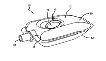
図1〜図7を参照するに、本発明のディスペンサーが示され、参照符号10で示されているのが分かる。ディスペンサー10は、液体Sを保持する液体容器12を包含する。ディスペンサー10は、更に、液体ポンプ14および空気ポンプ16を包含する(図4および図5)。空気ポンプ16が一回分の量の空気を混合ユニット18へと前進させるように作動している間、液体ポンプ14は、一回分の量の液体Sを混合ユニット18へと前進させるように作動する。ディスペンサー10は、混合ユニット18において空気と液体とを混合することにより、所望の製品を生成する。
Referring to FIGS. 1-7, it can be seen that the dispenser of the present invention is shown and designated by the
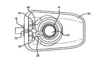
液体ポンプ14は、ベース20および液体ドーム22で形成される。液体ドーム22は、ベース20に取り付けられて、押し出し式液体チャンバ24を形作る。押し出し式液体チャンバ24は、液体容器12内の液体Sと液体入口弁2を通して流体連通する(図7〜図9)。押し出し式液体チャンバ24は、また、混合ユニット18へと通じる液体出口通路28とも流体連通する(図3)。液体入口弁26は、押し出し式液体チャンバ24内への流体流れを規制し、液体出口通路28の特殊な構造は、押し出し式液体チャンバ24から混合ユニット18内への流体流れを規制する機能を持つ(すなわち、前記液体出口通路の構造に起因して、液体出口通路28の特殊な構造は弁として機能する)。この構造について、本明細書中以下により詳細に開示する。
The
液体ドーム22は、弾性であるため、ベース20の方向に押し込むことができ、これにより、押し出し式液体チャンバ24を拡張又は膨張容積(図7)から圧縮又は収縮容積(図8)へと押し出すことができる。液体ドーム22上の圧力が解放されると、液体ドーム22は、十分な弾性により、前記押し出し位置から図7に示す静止位置へと弾性的に戻ることができる。液体ドーム22がベース20に向かって押されて、押し出し式液体チャンバ24が圧縮容積に移動すると、押し出し式液体チャンバ24内の圧力が増加し、その内容物は押し出し式液体チャンバ24から出て行き、液体出口通路28内へと入る。液体ドーム22から圧力が解放されると、液体ドーム22はその通常の静止位置へと弾性的に戻り、押し出し式液体チャンバ24をその拡張容積へと戻す。拡張時、押し出し式液体チャンバ24内に真空が発生し、液体Sは液体入口弁26を通して引き込まれ、これにより、押し出し式液体チャンバ24内に次の一回分の量の液体Sが再充填される。
Since the
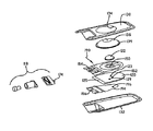
この実施例において、図6に示すように、液体容器12は、頂部フィルム30がその周辺において底部フィルム32に溶着されて形成される。液体ポンプ14は、頂部フィルム30において液体容器12に取り付けられる。より詳細には、液体ポンプ14のドーム20は、頂部フィルム30のポンプ開口34を通して延び、液体ポンプ14は溶着又は適当な接着剤によってこの開口34において取り付けられる。あるいは、ポンプ開口34を頂部フィルム30から省略してもよく、液体ポンプ14を完全に液体容器12の内側に保持して、可撓性頂部フィルム30を通して操作可能なようにしてもよい。頂部フィルム30および底部フィルム32は封止された可撓性フィルムであるため、前記押し出し式液体チャンバ24の収縮および拡張時に、一回分の量の液体Sが容器12内から押し出し式液体チャンバ24へと引き込まれるのにつれて、液体容器12がへこむ。
In this embodiment, as shown in FIG. 6, the
次に、特に図4〜図6を参照するに、空気ポンプ16が、ベース36とこのベース36に取り付けられた空気ドーム38とで形成され、押し出し式空気チャンバ40を形作っていることが分かる。押し出し式空気チャンバ40は、空気入口弁42(図7〜図9)を通して大気と流体連通し、これにより、前記大気は空気源として機能する。押し出し式空気チャンバ40は、また、混合ユニット18へと通じる空気出口通路44(図5)とも流体連通する。空気入口弁42は、押し出し式空気チャンバ40内への空気流れを規制し、空気出口通路44の特殊な構造は、押し出し式空気チャンバ40から混合ユニット18への空気流れを規制する機能を持つ。この特殊な構造について、本明細書中以下に詳細に開示する。
4-6, it can be seen that the
空気ドーム38は、弾性であるため、ベース36が液体ポンプ14の方向に押されると、空気ドーム38はベース20と接触し、ベース36に向かって圧縮され、これにより、押し出し式液体チャンバ40は拡張又は膨張容積(図7)から圧縮又は収縮容積(図8)へとへこまされる。ベース36への圧力が解放されると、空気ドーム38は、十分な弾性により、前記押し出し位置から図7に示す静止位置へと弾性的に戻ることができる。空気ドーム38がベース36に向かって押されて、押し出し式空気チャンバ40が圧縮容積になると、押し出し式空気チャンバ40内において圧力が増加し、その内容物は押し出し式空気チャンバ40から出て行き、空気出口通路44に入る。圧力が空気ドーム38から解放されると、空気ドーム38はその通常の静止位置へと弾性的に戻り、その結果、押し出し式空気チャンバ40はその拡張容積へと戻る。前記拡張時において、押し出し式空気チャンバ40内に真空が発生し、空気入口弁42を通して空気が引き込まれ、これにより、次の一回分の量の空気が押し出し式空気チャンバ40に再充填される。
Because the
この実施例において、図6に示すように、空気ポンプ16は、底部フィルム32において液体容器12に取り付けられる。より詳細には、空気ポンプ16のベース36は、底部フィルム32のポンプ開口46を通して延び、空気ポンプ16はこの開口46において溶着又は適当な接着剤によって取り付けられる。あるいは、液体ポンプ14について説明したように、空気ポンプ16を完全に液体容器12の内側に保持し、可撓性底部フィルム32を通して操作可能なようにしてもよい。
In this embodiment, the
図面に示すように、液体ポンプ14および空気ポンプ16は好適には互いに整列され、液体ポンプ14のベース20は好適には空気ポンプ16の空気ドーム38に隣接する。このような構造により、ディスペンサー10を指で持ってポンプ14又は16を押し、および前記親指でポンプ14又は16のうちの他方を押すことにより、ドーム22および38が相互に近づくように同時に圧迫することが可能になる。図示の構成において、液体ポンプ14の液体ドーム22にアクセスし、操作すると同時に、空気ポンプ16のベース36にアクセスし、操作することができ、前記2つを相互に近づくように圧迫することで押し出し式液体チャンバ24および押し出し式空気チャンバ40両方がへこまされる。液体容器12は、好適には、このような片手での操作に適したサイズにされる。ベース20が空気ドーム38に隣接することで、液体ポンプ14および空気ポンプ16がこのように圧迫されると、押し出し式液体チャンバ24および押し出し式空気チャンバ40が実質的に同時にへこまされる。チャンバ24および40がへこまされると、液体Sおよび空気は、それぞれ液体出口通路28および空気出口通路44を通して混合ユニット18内へと強制移動させられる。混合ユニット18において、前記一回分の量の空気および液体をさらに混合する構造が設けられる。前記液体が発泡可能な液体(例えば、石鹸又は発泡性の手用除菌剤)である場合、前記混合構造により、均一な泡が出口48において分与される。
As shown in the drawings, the
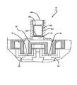
この実施例の構造のさらなる詳細は、以下のディスペンサー10の機能についての開示において、理解されよう。図7において、ディスペンサー10の断面が示されており、ディスペンサー10は静止位置にある(すなわち、作動していない)。この非作動状態において、押し出し式液体チャンバ24は一回分の量の液体Sを収容し、押し出し式空気チャンバ40は一回分の量の空気を収容する。これらの押し出し式チャンバがそれぞれへこまされると、前記一回分の量の液体および前記一回分の量の空気が混合ユニット18へと前進する。これを図8に示し、そこでは、液体ポンプ14および空気ポンプ16はどちらも作動している。より詳細には、ドーム22および38を圧迫することにより、押し出し式液体チャンバ24および押し出し式空気チャンバ40の容積が減少している。
Further details of the construction of this embodiment will be understood in the following disclosure of the function of the
液体ポンプ14において、押し出し式液体チャンバ24がへこまされると、その内部に保持されている液体Sが液体出口通路28内へと、そしてこの液体出口通路28を通して強制移動される。流体入口弁26は閉まっているため、液体出口通路28は押し出し式液体チャンバ24からの唯一の出口である。図7および図8に示すように、フラッパ50が可撓性ドーム22から延びて、ベース20にある入口開口52を被覆している。静止時および作動時の両方において、このフラッパ50は入口開口52上に延びており、押し出し式液体チャンバ24の内容物が液体容器12に再度入らないようにしている。押し出し式液体チャンバ24の容積が減少すると、その内部の液体Sは液体出口通路28へと前進するしかなくなる。図6、図10および図11に示すように、液体出口通路28は、頂部フィルム54および底部フィルム56で形成される。これらの頂部フィルム54および底部フィルム56は、その周囲において互いに密着され、これにより、静止時において、頂部フィルム54および底部フィルム56は貼りつき合って、液体がその間を流れるのを阻止する(すなわち、液体出口通路28は閉められる)。しかし、押し出し式液体チャンバ24がへこむと、押し出し式液体チャンバ24から液体を強制移動させる圧力が十分に高くなり、その結果、この液体出口通路28が開き、液体Sは混合ユニット18へと移動する。
In the
同様に、空気ポンプ16において、押し出し式空気チャンバ40がへこまされると、その内部に保持されている空気は、空気出口通路44の内部へ、そしてこの空気出口通路44を通して強制移動される。空気入口弁42は閉められているため、空気出口通路44は、押し出し式空気チャンバ40からの唯一の出口である。図7および図8に示すように、フラッパ58は、可撓性ドーム38から延びて、ベース36にある入口開口60を被覆する。静止時および作動時の両方において、このフラッパ弁58は入口開口60上に延びており、押し出し式空気チャンバ40の内容物が大気へと出て行かないようにする。押し出し式空気チャンバ40の容積が減少すると、その内部の空気は空気出口通路44に向かって前進するしかなくなる。図6、図10および図11に示すように、空気出口通路44は、頂部フィルム62および底部フィルム64で形成される。頂部フィルム62および底部フィルム64は、その周囲において互いに密着され、通常は貼りつき合って、その間を空気が流れないようになっている。しかし、押し出し式空気チャンバ40がへこまされると、押し出し式空気チャンバ40から強制移動される空気の圧力は十分に高くなり、その結果、この空気出口通路が開き、空気は混合ユニット18へと移動する。
Similarly, in the
次に図9を参照するに、押し出し式液体チャンバ24および押し出し式空気チャンバ40への一回分の量の液体および空気の再充填について説明する。液体ドーム22上への押し出し力が解除されると、図9に示すように、液体ドーム22は自然にその非押し出し位置へと戻る。この液体ドーム22の動きにより、押し出し式液体チャンバ24内に真空が発生し、その結果、フラッパ50はベース20にある入口開口52から引き離され、その結果、次の一回分の量の液体Sが液体ポンプ14内へと引き込まれる。液体出口通路28も、図11に示すように、再び平坦状態に戻ることが理解されよう。同様に、空気ドーム38上の押し出し力が解除されると、図9に示すように、空気ドーム38は自然にその非押し出し位置へと戻る。この空気ドーム38の動きにより、押し出し式空気チャンバ40内において真空が発生し、その結果、フラッパ58はベース36にある入口開口60から引き離され、その結果、次の一回分の量の空気が液体ポンプ16内へと引き込まれる。空気出口通路44も、図11に示すように、平坦に戻る。
Referring now to FIG. 9, the refilling of a single volume of liquid and air into the
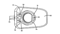
図3、図5、図6および図12を参照するに、液体出口通路28は液体入口72においてマニホールド70に通じる一方、空気出口通路44は空気入口74においてマニホールド70に通じることが分かる。これらの別個の空気通路および液体通路は、マニホールド70においてひとつになり、共通出口通路76を通して出口48に向かって強制移動される。少なくとも1つの網目スクリーン78が出口通路76に設けられ、これにより、前記別個の空気通路および液体通路の結合部において形成された空気および液体の粗い混合物をより均一な混合物に均質化できるようにする。前記液体が発泡可能な液体である場合、前記均質化により、良質な泡製品を出口48において分与することができる。特定の実施例によれば、少なくとも1つの網目スクリーン78が混合カートリッジ80において第1のスクリーンとして設けられ、これは、網目スクリーン78および第2の網目スクリーン84によって境界付けられた管82となる。
3, 5, 6 and 12, it can be seen that the
混合ユニット18は、硬質のカヌーフィットメント86を提供する。硬質のカヌーフィットメント86は、前記液体容器の頂部フィルム30および底部フィルム32に溶着される。図6に示すように、液体出口通路28の頂部フィルム54および底部フィルム56と、空気出口通路44の頂部フィルム62および底部フィルム64とは、マニホールド70の液体入口72および空気入口74にヒートシールされる。
The mixing
この実施例において、空気ポンプに対向する液体ポンプを有するディスペンサー10が提供され、これにより、前記液体ポンプおよび前記空気ポンプを相互に向かって圧迫することで、これらのポンプを作動させ、空気と液体とを混合して、所望の製品を分与することができる。特定の実施例において、前記液体として発泡可能な液体(例えば、石鹸又は発泡性消毒剤)が選択され、分与される製品は泡形態をとる。前記液体容器は密閉され、好適には可撓性フィルムから形成され、これにより、前記容器がへこまされると、一回分の量の液体が前記押し出し式液体チャンバ内へと引き込まれる。前記容器を押し出し式に作ることにより、前記容器中の液体は、前記押し出し式液体チャンバへの入口弁の位置において常時存在するようになる。その結果、確実に、一回分の量の液体が、前記押し出し式液体チャンバの拡張時において、前記押し出し式液体チャンバ内に一貫して引き込まれる。より硬質の通気式容器構造も用いることができるが、前記押し出し式液体チャンバ内に空気が入るのを回避するために、時として特定の向きにさせる必要がある場合がある。この実施例の対向する液体ポンプおよび空気ポンプによる構造は使い易いが、前記液体ポンプおよび空気ポンプを異なる位置に配置してもよいことが理解されよう。実際、前記空気ポンプが空気源と連通しかつ前記液体ポンプが液体源と連通し、なおかつ、これらの両方のポンプが共通出口と連通して、2つの別々の成分の混合を可能にしさえすれば、前記液体ポンプおよび前記空気ポンプは任意の位置に配置することができる。下記に開示される別の実施例において、前記液体ポンプが前記空気ポンプによって包囲され、ポンプ内にポンプがある構造になっている。この構造は、前記液体容器の片側から延びるものである。
In this embodiment, a
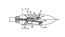
次に図13〜図18を参照するに、ポンプ内にポンプがある構造を示すディスペンサーの一実施例が示され、参照符号110によって示されている。ディスペンサー110は、液体Sを保持する液体容器112を包含する。ディスペンサー110は、更に、液体ポンプ114および空気ポンプ116(図17)を包含する。液体ポンプ114は、一回分の量の液体Sを混合ユニット118へと前進させるように作動する。一方、空気ポンプ116は、一回分の量の空気を混合ユニット118へと前進させるように作動する。ディスペンサー110は、混合ユニット118において空気と液体とを混合することにより、所望の製品を生成する。
Referring now to FIGS. 13-18, one embodiment of a dispenser showing the construction of the pump within the pump is shown and indicated by
液体ポンプ114は、弾性液体ドーム122と、より硬質のチャンネルプレート120および弁フィルム190との間の相互作用により、形成される。液体ドーム122は、チャンネルプレート120に取り付けられて、押し出し式液体チャンバ124を形作る。押し出し式液体チャンバ124は、液体容器112内の液体Sと液体入口弁126(図18)を通して流体連通する。液体入口弁126は、押し出し式液体チャンバ124内への液体Sの流れを規制する。押し出し式液体チャンバ124は、また、混合ユニット118へと通じる液体出口通路128(図18)とも流体連通する。この実施例の液体出口通路128は、前述した実施例の液体出口通路28とは構造が異なるが、本明細書中以下により詳細に説明するように、同様に、押し出し式液体チャンバ124から混合ユニット118内へと流れる流体の流れを規制する機能を持つ。
The liquid pump 114 is formed by the interaction between the elastic
次に、特に図15〜図17を参照するに、液体ポンプ114の液体ドーム122を包囲する弾性空気ドーム138で空気ポンプ116が形成されていることが、分かる。この空気ドーム138もチャンネルプレート120に取り付けられ、これにより、押し出し式空気チャンバ140を形作る。スペーサ部材141は空気ドーム138から押し出し式空気チャンバ140内へと延びて、液体ドーム122と接触するか又は液体ドーム122に近接する。このスペーサ部材141は、空気ドーム138が押圧されると液体ドーム122をへこませ始めるため、有利である。押し出し式空気チャンバ140は、空気入口弁142(図13および図14)を通して大気と流体連通し、これにより、前記大気は空気源として機能する。この実施例において、空気入口弁142は、スペーサ部材141を貫通する通路143(図17)であり、また、ディスペンサー110のユーザの手の指、特に親指によって塞がれるか又は塞がれないことにより、空気流れを規制する機能を持つ。押し出し式空気チャンバ140は、また、混合ユニット118へと通じる空気出口通路144(図18)とも流体連通する。空気入口弁142が、押し出し式空気チャンバ140内への空気流れを規制するように、設けられる。この実施例の空気出口通路144は、前記した実施例の空気出口通路44と構造が異なるが、本明細書中以下により詳細に説明するように、同様に、押し出し式空気チャンバ140から混合ユニット118内への流体流れを規制する機能を持つ。
Next, with particular reference to FIGS. 15-17, it can be seen that the air pump 116 is formed of an
液体ポンプ114の液体ドーム122および空気ポンプ116の空気ドーム138はどちらとも弾性であるため、チャンネルプレート120の方向へ押圧することができ、これにより、そのそれぞれの押し出し式液体チャンバ124および押し出し式空気チャンバ140を拡張容積(図17)から圧縮容積へとへこませる。空気ドーム138上の圧力が解放されると、ドーム122および138の両方は、十分な弾性により、前記押し出し位置から図17に示す静止位置へと弾性的に戻る。前述したように、空気ドーム138上の圧力は、スペーサ部材141によって液体ドーム122へと平行移動される。空気ドーム138がベース120に向かって押されて、押し出し式液体チャンバ124および押し出し式空気チャンバ140の両方が圧縮容積になると、2つのチャンバ124および140内において圧力が増加し、その内容物は、そのそれぞれの液体出口128および空気出口通路144に入る。空気ドーム138から圧力が解放されると、液体ドーム122および空気ドーム138の両方はその通常の静止位置へと弾性的に戻り、これにより、押し出し式液体チャンバ124および押し出し式空気チャンバ140はその拡張容積へと戻る。前記拡張時において、押し出し式液体チャンバ128内および押し出し式空気チャンバ140内において真空が発生し、液体入口弁126および空気入口弁142を通して液体および空気が引き込まれ、これにより、次の一回分の量の液体および空気が押し出し式液体チャンバ128および押し出し式空気チャンバ140に再充填される。
Since both the
この第2の実施例において、図15および図16に示すように、空気ポンプ116は、頂部フィルム130において液体容器112に取り付けられる。より詳細には、空気ポンプ116の空気ドーム138は、頂部フィルム30のポンプ開口134を通して延び、空気ポンプ116はドーム周縁139において溶着又は適当な接着剤によってこの開口134に取り付けられる。あるいは、空気ポンプ116を完全に液体容器112の内側に保持して、可撓性頂部フィルム130を通して操作可能なようにしてもよい。
In this second embodiment, as shown in FIGS. 15 and 16, the air pump 116 is attached to the
図15に示すように、空気ポンプ116は液体ポンプ114を同軸に包囲するが、液体ポンプ114は偏心され得る。液体ポンプ114および空気ポンプ116は、液体ドーム122および空気ドーム138を弁フィルム190に溶着することによって又は接着することにより、形成される。弁フィルム190は、チャンネルプレート120と共に、液体ポンプ114が機能するのに必要な弁構造を提供する。空気ポンプ116の機能は、空気入口弁142の機能により促進される。この構造により、ユーザは底部フィルム132の下側に手の指をあててディスペンサー110を持ち、親指で空気入口弁142を押圧かつ塞ぐことにより、ドーム122および138の両方をへこませることが可能となる。液体容器112は、好適には、このような片手操作に適したサイズにされる。チャンバ124および140がへこまされることにより、液体Sおよび空気はそのそれぞれの液体出口通路128および空気出口通路144から混合ユニット118内へと強制移動される。混合ユニット118は、この実施例において、第1の実施例の混合ユニット118と実質的に同一である。
As shown in FIG. 15, the air pump 116 coaxially surrounds the liquid pump 114, but the liquid pump 114 may be eccentric. The liquid pump 114 and air pump 116 are formed by welding or adhering the
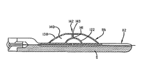
この第2の実施例の構造のさらなる詳細は、ディスペンサー110の機能に関する以下の開示により、理解されよう。図17において、ディスペンサー110の断面が示されている。ディスペンサー110は、静止位置にある(すなわち、作動していない)。この非作動状態において、押し出し式液体チャンバ124は一回分の量の液体Sを収容し、押し出し式空気チャンバ140は一回分の量の空気を収容する。これらの押し出し式チャンバをそれぞれへこませることで、前記一回分の量の液体および前記一回分の量の空気を混合ユニット118へと前進させることができる。これらの押し出し式チャンバは、手の指の圧力によってへこませ、空気ドーム138を移動させ、よって液体ドーム122をチャンネルプレート120に向かって移動させる。
Further details of the structure of this second embodiment will be understood from the following disclosure regarding the function of the
液体ポンプ114において、押し出し式液体チャンバ124がへこまされると、その内部に保持されている液体Sは液体出口通路128内へと、そしてこの液体出口通路128を通して強制移動される。液体入口弁126は閉まっているため、液体出口通路128は、押し出し式液体チャンバ124からの唯一の出口である。弁フィルム190と、チャンネルプレート120と、チャンネルフィルム194(図15および図16)とのアセンブリの平面図である図18に示すように、弁フィルム190の半島状伸長部192に設けられたフラッパ150が、チャンネルプレート120にある液体入口開口152を塞ぐ。静止時および作動時のどちらにおいても、このフラッパ150は入口開口152上に延び、これにより、押し出し式液体チャンバ124の内容物が液体容器112内に再度入らないようにする。押し出し式液体チャンバ124の容積が減少すると、その内部の液体Sは液体出口通路128に向かって前進するしかなくなる。液体出口通路128は、チャンネルフィルム194によって被覆されたチャンネルプレート120の液体チャンネル121(図16)により形成される。液体チャンネル121は、チャンネルプレート120にある液体出口開口123からその前縁部125へと延びる。この前縁部125において、弁フィルム190の延長にある頂部フィルム154と、チャンネルフィルム194の延長にある底部フィルム156とが、混合ユニット118の液体入口ポート172の周囲において互いに密着される。
In the liquid pump 114, when the push-out liquid chamber 124 is recessed, the liquid S held therein is forcibly moved into the
同様に、空気ポンプ116において、押し出し式空気チャンバ140がへこまされると、その内部に保持されている空気は空気出口通路144内に、そしてこの空気出口通路144を通して強制移動される。作動時には空気入口弁142はユーザの手の指、特に親指によって閉められているため、空気出口通路144は、押し出し式空気チャンバ140からの唯一の出口である。図15、図16および図18に示すように、押し出し式空気チャンバ140の容積は、空気出口開口129を通して、チャンネルプレート120にある空気チャンネル127と連通する。空気入口弁142がユーザの指、特に親指によって塞がれかつ押し出し式空気チャンバ140の容積が減少すると、その内部の空気は空気出口通路144に前進するしかなくなる。空気出口通路144はチャンネルフィルム194によって被覆された空気チャンネル127により形成され、この空気出口通路144はチャンネルプレート120の前縁部125へと延びる。この前縁部125において、弁フィルム190の延長である頂部フィルム154と、チャンネルフィルム194の延長である底部フィルム156とが、混合ユニット118の空気入口ポート174の周囲において互いに密着される。
Similarly, in the air pump 116, when the push-out
空気ドーム138への押圧力が解除されると、空気ドーム138および液体ドーム122はどちらとも、図17に示すように、その非押し出し位置へと戻る。この液体ドーム122の動きにより、押し出し式液体チャンバ124内において真空が発生し、その結果、フラッパ150はチャンネルプレート120の液体入口開口152から引き離され、その結果、次の一回分の量の液体Sが液体ポンプ114内へと引き込まれる。チャンネルフィルム194は液体入口開口152と整列された開口196を包含し、これにより、チャンネルフィルム194は次の一回分の量の液体の充填と干渉しない。また、空気ドーム138の動きによっても、押し出し式空気チャンバ140内に真空が発生し、その結果、通路143を通して空気が引き込まれ、これにより、押し出し式空気チャンバ140に空気が充填される。
When the pressing force to the
前述して開示した第1の実施例と同様に、別個の空気通路および液体通路が混合ユニット118においてひとつになる。混合ユニット118は、混合ユニット18と実質的に同一である。
Similar to the first embodiment disclosed above, separate air and liquid passages are combined in the
この実施例において、液体ポンプを包囲する空気ポンプを有するディスペンサー110が提供され、これにより、前記空空気ポンプが押圧されると、前記空気ポンプおよび前記液体ポンプのどちらとも作動させ、空気と液体とを混合して、所望の製品を分与することができる。特定の実施例において、前記液体として発泡可能な液体(例えば、石鹸又は発泡性消毒剤)が選択され、分与される製品は泡形態をとる。前記液体容器は密閉され、好適には可撓性フィルムから形成され、これにより、前記容器がへこまされると、一回分の量の液体が前記押し出し式液体チャンバ内へと引き込まれる。前記容器を押し出し式に作ることにより、前記容器中の液体は、前記押し出し式液体チャンバへの入口弁の位置において常時存在するようになる。その結果、確実に、一回分の量の液体が、前記押し出し式液体チャンバの拡張時において、前記押し出し式液体チャンバ内に一貫して引き込まれる。より硬質の通気式容器構造も用いることができるが、前記押し出し式液体チャンバ内に空気が入るのを回避するために時として特定の向きにさせる必要がある場合がある。
In this embodiment, a
以上述べたことから、本発明は、液体を空気と混合して所望の最終製品を生成するのに適した手持ち型の個人用ディスペンサーを提供することにより、ディスペンサーの技術を進展させることが明らかであろう。本発明は、いくつかの実施例において、泡状の手用石鹸又は泡状の手用除菌剤用の個人用ディスペンサーを提供することを意図しているが、本発明はこれに限定されずまたこれによっても限定されない。また、本発明を用いて、実質的に任意の目的のために、実質的に任意の液体を空気と混合してもよい。特許請求の範囲の記載が、本発明を限定する役目を果たすものである。 From the foregoing, it is clear that the present invention advances dispenser technology by providing a handheld personal dispenser suitable for mixing a liquid with air to produce the desired end product. I will. While the present invention is intended in some embodiments to provide a personal dispenser for foamed hand soap or foamed hand sanitizer, the present invention is not so limited. Moreover, it is not limited by this. The present invention may also be used to mix virtually any liquid with air for virtually any purpose. The claims will serve to limit the invention.
Claims (16)
液体を保持する押し出し式液体容器と、
混合チャンバと、
押し出し式液体チャンバを包含する液体ポンプであって、前記押し出し式液体チャンバが液体出口通路を通して前記混合チャンバと連通し、また前記押し出し式液体チャンバが拡張容積と収縮容積との間で操作されるようにされ、更に前記押し出し式液体チャンバが弁を通して前記液体チャンバ内の前記液体と連通する、液体ポンプと、
押し出し式空気チャンバを包含する空気ポンプであって、前記押し出し式空気チャンバが空気出口通路を通して前記混合チャンバと連通し、また前記押し出し式空気チャンバが拡張容積と収縮容積との間で操作されるようにされ、更に前記押し出し式空気チャンバが弁を通して前記ディスペンサーの外部の空気と連通する、空気ポンプと、
を包含し、
前記押し出し式液体チャンバおよび前記押し出し式空気チャンバは片手で操作可能なように前記押し出し式液体容器に取り付けられ、
前記押し出し式液体チャンバが前記収縮容積から前記拡張容積へと拡張すると、前記液体の一部分が前記押し出し式液体チャンバ内へと引き込まれ、また、前記押し出し式液体チャンバが前記拡張容積から前記収縮容積へと収縮すると、前記押し出し式液体チャンバ内の前記液体の一部分が前記押し出し式液体チャンバ内から吐出されて、前記液体出口通路へと強制移動され、
前記押し出し式空気チャンバが前記収縮容積から前記拡張容積へと拡張すると、空気が前記押し出し式空気チャンバ内へと引き込まれ、また前記押し出し式空気チャンバが前記拡張容積から前記収縮容積へと収縮すると、前記押し出し式空気チャンバ内の空気が前記押し出し式空気チャンバ内から吐出されて、前記空気出口通路へと強制移動され、
前記空気出口通路を通して強制移動された空気と、前記液体出口通路を通して強制移動された液体とにより、空気および液体の混合物が前記混合チャンバにおいて生成されるようにした手持ち型ディスペンサー。 A hand-held dispenser for dispensing air mixed with liquid,
An extruded liquid container for holding liquid;
A mixing chamber;
A liquid pump including an pushable liquid chamber, wherein the pushable liquid chamber is in communication with the mixing chamber through a liquid outlet passage, and the pushable liquid chamber is operated between an expansion volume and a contraction volume. A liquid pump, wherein the pushable liquid chamber is in communication with the liquid in the liquid chamber through a valve;
An air pump including an extruded air chamber, wherein the extruded air chamber communicates with the mixing chamber through an air outlet passage, and wherein the extruded air chamber is operated between an expansion volume and a contraction volume An air pump, wherein the push-out air chamber is in communication with air outside the dispenser through a valve;
Including
The pushable liquid chamber and the pushable air chamber are attached to the pushable liquid container so that they can be operated with one hand;
As the pushable liquid chamber expands from the contracted volume to the expanded volume, a portion of the liquid is drawn into the pushable liquid chamber and the pushable liquid chamber moves from the expanded volume to the contracted volume. And a part of the liquid in the push-out liquid chamber is discharged from the push-out liquid chamber and forcedly moved to the liquid outlet passage,
When the push-out air chamber expands from the contracted volume to the expanded volume, air is drawn into the push-out air chamber and when the push-out air chamber contracts from the expanded volume to the contracted volume; The air in the push-out air chamber is discharged from the push-out air chamber and is forcibly moved to the air outlet passage;
A hand-held dispenser wherein a mixture of air and liquid is generated in the mixing chamber by air forced through the air outlet passage and liquid forced through the liquid outlet passage.
Applications Claiming Priority (2)
| Application Number | Priority Date | Filing Date | Title |
|---|---|---|---|
| US12/288,785 US7984831B2 (en) | 2008-10-23 | 2008-10-23 | Handheld dispensers for personal use |
| US12/288,785 | 2008-10-23 |
Publications (2)
| Publication Number | Publication Date |
|---|---|
| JP2010100340A true JP2010100340A (en) | 2010-05-06 |
| JP5546827B2 JP5546827B2 (en) | 2014-07-09 |
Family
ID=41572460
Family Applications (1)
| Application Number | Title | Priority Date | Filing Date |
|---|---|---|---|
| JP2009244731A Expired - Fee Related JP5546827B2 (en) | 2008-10-23 | 2009-10-23 | Handheld dispenser for personal use |
Country Status (14)
| Country | Link |
|---|---|
| US (1) | US7984831B2 (en) |
| EP (1) | EP2179796B1 (en) |
| JP (1) | JP5546827B2 (en) |
| KR (1) | KR20100045390A (en) |
| CN (1) | CN101722122B (en) |
| AU (1) | AU2009227899B2 (en) |
| BR (1) | BRPI0904314A2 (en) |
| CA (1) | CA2683324A1 (en) |
| DK (1) | DK2179796T3 (en) |
| ES (1) | ES2443291T3 (en) |
| HK (1) | HK1140982A1 (en) |
| MY (1) | MY146327A (en) |
| PT (1) | PT2179796E (en) |
| TW (1) | TW201020030A (en) |
Cited By (3)
| Publication number | Priority date | Publication date | Assignee | Title |
|---|---|---|---|---|
| JP2013535382A (en) * | 2010-07-26 | 2013-09-12 | ジョン シク ハン | Double pack |
| JP2019509030A (en) * | 2016-02-10 | 2019-04-04 | エクスプロラメッド・エヌシー7・インコーポレイテッドExploramed Nc7, Inc. | Milking container assembly and method |
| JP2022058163A (en) * | 2020-09-30 | 2022-04-11 | 富佳生技股▲ふん▼有限公司 | Liquid transfer device |
Families Citing this family (25)
| Publication number | Priority date | Publication date | Assignee | Title |
|---|---|---|---|---|
| US20110182652A1 (en) * | 2010-01-22 | 2011-07-28 | Hannah Chung | Wearable Sanitizing Gel Dispenser, Kit, and Associated Methods |
| US9637272B2 (en) | 2010-09-02 | 2017-05-02 | Kraft Foods Group Brands Llc | Containers and methods for mixing and dispensing beverage concentrates |
| CN103347800B (en) | 2010-12-14 | 2016-07-06 | 卡夫食品集团品牌有限责任公司 | Container and method for fluid partitioning before a distribution |
| CA2773801C (en) | 2011-04-08 | 2019-08-06 | Gotohti.Com Inc. | Dispenser with sound generators |
| US8820579B2 (en) * | 2011-09-28 | 2014-09-02 | Leonard B. Wood | Fluid reservoir shell |
| US8988228B2 (en) | 2012-04-03 | 2015-03-24 | Swipesense, Inc. | Electronic module for tracking hand hygiene |
| US9060655B2 (en) | 2012-06-13 | 2015-06-23 | Swipesense, Inc. | Dispenser for hand sanitizer |
| US10121149B2 (en) | 2012-09-17 | 2018-11-06 | Sage Products, Llc | Methods for ensuring and tracking hand hygiene compliance |
| US11123153B2 (en) | 2012-09-17 | 2021-09-21 | Sage Products, Llc | Method and system for ensuring and tracking hand hygiene compliance |
| FR3001719B1 (en) * | 2013-02-07 | 2016-02-05 | Gb Dev | FLUID DISPENSING DEVICE AND METHOD FOR MANUFACTURING SUCH A DEVICE. |
| FR3002215B1 (en) * | 2013-02-20 | 2015-03-20 | Rexam Dispensing Smt | POCKET HAVING A SOFT ENVELOPE DELIMITATING A RESERVOIR IN WHICH A PRODUCT TO BE DISTRIBUTED IS INTENDED TO BE CONDITIONED |
| US20140252033A1 (en) * | 2013-03-08 | 2014-09-11 | Pouch Pac Innovations, Llc | Fitment for flexible pouch |
| USD742137S1 (en) | 2013-03-15 | 2015-11-03 | Buckeye International, Inc. | Dispenser for dispensing cleaning solutions |
| US20160073833A1 (en) * | 2014-09-12 | 2016-03-17 | Gojo Industries, Inc. | Multi-chamber refill unit and dispensers |
| USD773849S1 (en) | 2015-03-13 | 2016-12-13 | Buckeye International, Inc. | Dispenser for dispensing a cleaning solution |
| KR101687341B1 (en) * | 2015-06-05 | 2016-12-16 | (주)에이치앤비메디텍 | Medical suction unit and fabrication method thereof |
| US10472162B2 (en) | 2016-09-09 | 2019-11-12 | The Clorox Company | Continuous spray dispenser for highly corrosive and other low compatibility products |
| US10278549B1 (en) | 2016-10-31 | 2019-05-07 | Gpcp Ip Holdings Llc | Counter-mounted skincare product dispenser |
| US10654059B2 (en) | 2017-03-30 | 2020-05-19 | 1Touch Holdings, Inc. | Self sealing airless measured dispenser |
| CN107374466A (en) * | 2017-09-12 | 2017-11-24 | 广州尚功塑胶有限公司 | A kind of push type foam maker |
| IT201700115255A1 (en) * | 2017-10-12 | 2019-04-12 | Taplast Srl | FLUID OR MIXTURE DELIVERY SYSTEM AND DEVICE USED IN THIS SYSTEM. |
| IT201700115249A1 (en) * | 2017-10-12 | 2019-04-12 | Taplast Srl | FLUID OR MIXTURE DELIVERY SYSTEM AND DEVICE USED IN THIS SYSTEM. |
| CN110252565B (en) * | 2019-07-12 | 2020-11-06 | 李秀春 | Dragging type sterilizing vehicle |
| ES2854199A1 (en) * | 2020-03-18 | 2021-09-20 | Vilas Joaquin Sabaris | IMPROVED DISINFECTING BRACELET (Machine-translation by Google Translate, not legally binding) |
| CN111674703B (en) * | 2020-06-18 | 2021-12-21 | 东莞市润科水墨有限公司 | Paint container device capable of preventing extrusion solution from blocking to cause poor performance effect |
Citations (2)
| Publication number | Priority date | Publication date | Assignee | Title |
|---|---|---|---|---|
| JP2004506511A (en) * | 2000-08-25 | 2004-03-04 | バルワー エス.アー.エス. | Dispenser with built-in pump |
| JP2006517858A (en) * | 2003-02-18 | 2006-08-03 | インクロ リミテッド | Dispenser pump |
Family Cites Families (22)
| Publication number | Priority date | Publication date | Assignee | Title |
|---|---|---|---|---|
| US3048878A (en) * | 1959-07-15 | 1962-08-14 | Kleer Site Corp | Eyeglass liquid applicator device |
| US3471064A (en) * | 1968-06-07 | 1969-10-07 | Leeds & Micallef | Foam generating and dispensing device |
| US5911716A (en) * | 1992-01-24 | 1999-06-15 | I-Flow Corporation | Platen pump |
| US6358239B1 (en) * | 1992-01-24 | 2002-03-19 | I-Flow Corporation | Platen pump |
| FR2778639B1 (en) * | 1998-05-18 | 2000-07-28 | Valois Sa | SAMPLE TYPE SPRAYING DEVICE |
| FR2791645B1 (en) * | 1999-04-02 | 2001-06-15 | Valois Sa | FLUID PRODUCT SAMPLE FOR PRESS |
| GB2378435B (en) * | 2000-06-06 | 2004-03-31 | Decko Products Inc | Dispensing pouch |
| IL149677A0 (en) * | 2002-05-15 | 2002-11-10 | Amir Genosar | Liquid dispenser |
| FR2844773B1 (en) * | 2002-09-24 | 2005-01-28 | Jerome Boumnso | DEVICE FORMING A PACKAGING OF VISCOUS PRODUCTS WITH COMPLETE VIDAGE THROUGH MANUAL PUMPING |
| US6855985B2 (en) * | 2002-09-29 | 2005-02-15 | Advanced Analogic Technologies, Inc. | Modular bipolar-CMOS-DMOS analog integrated circuit & power transistor technology |
| JP4027390B2 (en) * | 2002-11-02 | 2007-12-26 | ケッテンバッハ ゲゼルシャフト ミット ベシュレンクテル ハフツング ウント コンパニー コマンディートゲゼルシャフト | Equipment for the storage and supply of viscous substances |
| IL155033A0 (en) * | 2003-03-23 | 2003-10-31 | Silex Projects Ltd | Flexible film package with integral dosing pump |
| FR2866321B1 (en) * | 2004-02-13 | 2007-05-18 | Lablabo | DEFORMABLE SOFT POUCH AND DEVICE FOR PACKAGING AND DISPENSING FLUID PRODUCTS. |
| US7419322B2 (en) * | 2004-03-10 | 2008-09-02 | Poly-D Llc | Fluid dispensing device with metered delivery |
| US20060186140A1 (en) * | 2005-02-24 | 2006-08-24 | Kanfer Joseph S | Fluid dispensers for personal use |
| US7780039B2 (en) * | 2006-04-28 | 2010-08-24 | Buckeye International, Inc. | Soap dispensing pump head with vacuum applying drip guard member |
| US20080077419A1 (en) * | 2006-09-27 | 2008-03-27 | Santiago Pamela M | System And Method For Training Employees Of An Organization To Align Their Job Activities To Achieving The Organization's Strategic Objectives |
| EP2125547A2 (en) * | 2006-12-11 | 2009-12-02 | Poly-D LLC | Dispensing stand-up pouch |
| WO2008080133A2 (en) * | 2006-12-21 | 2008-07-03 | Chef'n Corporation | Fluid dispenser |
| US8136700B2 (en) * | 2007-02-23 | 2012-03-20 | Sealed Air Corporation (Us) | Dual chambered fluid dispenser with mixing chamber |
| JP5021771B2 (en) * | 2007-03-14 | 2012-09-12 | ポリィ−ディー・エルエルシー | Dispensing device with dual pump system |
| WO2008118830A1 (en) * | 2007-03-26 | 2008-10-02 | Poly-D, Llc | Hanging liquid dispenser |
-
2008
- 2008-10-23 US US12/288,785 patent/US7984831B2/en not_active Expired - Fee Related
-
2009
- 2009-10-21 TW TW098135604A patent/TW201020030A/en unknown
- 2009-10-22 AU AU2009227899A patent/AU2009227899B2/en not_active Expired - Fee Related
- 2009-10-22 KR KR1020090100549A patent/KR20100045390A/en active IP Right Grant
- 2009-10-22 CA CA2683324A patent/CA2683324A1/en not_active Abandoned
- 2009-10-22 CN CN200910173996.5A patent/CN101722122B/en not_active Expired - Fee Related
- 2009-10-23 BR BRPI0904314-4A patent/BRPI0904314A2/en not_active IP Right Cessation
- 2009-10-23 JP JP2009244731A patent/JP5546827B2/en not_active Expired - Fee Related
- 2009-10-23 ES ES09173891.4T patent/ES2443291T3/en active Active
- 2009-10-23 MY MYPI20094476A patent/MY146327A/en unknown
- 2009-10-23 PT PT91738914T patent/PT2179796E/en unknown
- 2009-10-23 DK DK09173891.4T patent/DK2179796T3/en active
- 2009-10-23 EP EP09173891.4A patent/EP2179796B1/en not_active Not-in-force
-
2010
- 2010-08-04 HK HK10107432.9A patent/HK1140982A1/en not_active IP Right Cessation
Patent Citations (2)
| Publication number | Priority date | Publication date | Assignee | Title |
|---|---|---|---|---|
| JP2004506511A (en) * | 2000-08-25 | 2004-03-04 | バルワー エス.アー.エス. | Dispenser with built-in pump |
| JP2006517858A (en) * | 2003-02-18 | 2006-08-03 | インクロ リミテッド | Dispenser pump |
Cited By (4)
| Publication number | Priority date | Publication date | Assignee | Title |
|---|---|---|---|---|
| JP2013535382A (en) * | 2010-07-26 | 2013-09-12 | ジョン シク ハン | Double pack |
| JP2019509030A (en) * | 2016-02-10 | 2019-04-04 | エクスプロラメッド・エヌシー7・インコーポレイテッドExploramed Nc7, Inc. | Milking container assembly and method |
| JP2021178180A (en) * | 2016-02-10 | 2021-11-18 | ウィロー・イノベイションズ・インコーポレイテッドWillow Innovations, Inc. | Breast pump container assembly and methods |
| JP2022058163A (en) * | 2020-09-30 | 2022-04-11 | 富佳生技股▲ふん▼有限公司 | Liquid transfer device |
Also Published As
| Publication number | Publication date |
|---|---|
| CN101722122B (en) | 2014-01-01 |
| CN101722122A (en) | 2010-06-09 |
| CA2683324A1 (en) | 2010-04-23 |
| KR20100045390A (en) | 2010-05-03 |
| ES2443291T3 (en) | 2014-02-18 |
| EP2179796B1 (en) | 2013-12-25 |
| JP5546827B2 (en) | 2014-07-09 |
| PT2179796E (en) | 2014-03-11 |
| BRPI0904314A2 (en) | 2010-11-09 |
| EP2179796A1 (en) | 2010-04-28 |
| AU2009227899A1 (en) | 2010-05-13 |
| US20100102085A1 (en) | 2010-04-29 |
| TW201020030A (en) | 2010-06-01 |
| HK1140982A1 (en) | 2010-10-29 |
| MY146327A (en) | 2012-07-31 |
| DK2179796T3 (en) | 2014-01-20 |
| AU2009227899B2 (en) | 2015-10-29 |
| US7984831B2 (en) | 2011-07-26 |
Similar Documents
| Publication | Publication Date | Title |
|---|---|---|
| JP5546827B2 (en) | Handheld dispenser for personal use | |
| TWI469759B (en) | Air piston and dome foam pump | |
| EP2134616B1 (en) | Dispenser with dual pump system | |
| TWI445513B (en) | Foam soap dispenser with stationary dispensing tube | |
| JP5112337B2 (en) | Self-cleaning foam discharge apparatus and foam discharge method | |
| US7861895B2 (en) | High velocity foam pump | |
| JP2006517859A (en) | Dispensing nozzle | |
| EP1503866B1 (en) | Liquid dispenser | |
| US8136700B2 (en) | Dual chambered fluid dispenser with mixing chamber | |
| US7762435B2 (en) | Dispensing apparatus |
Legal Events
| Date | Code | Title | Description |
|---|---|---|---|
| A621 | Written request for application examination |
Free format text: JAPANESE INTERMEDIATE CODE: A621 Effective date: 20121023 |
|
| A977 | Report on retrieval |
Free format text: JAPANESE INTERMEDIATE CODE: A971007 Effective date: 20130930 |
|
| A131 | Notification of reasons for refusal |
Free format text: JAPANESE INTERMEDIATE CODE: A131 Effective date: 20131008 |
|
| A521 | Request for written amendment filed |
Free format text: JAPANESE INTERMEDIATE CODE: A523 Effective date: 20131129 |
|
| TRDD | Decision of grant or rejection written | ||
| A01 | Written decision to grant a patent or to grant a registration (utility model) |
Free format text: JAPANESE INTERMEDIATE CODE: A01 Effective date: 20140416 |
|
| A61 | First payment of annual fees (during grant procedure) |
Free format text: JAPANESE INTERMEDIATE CODE: A61 Effective date: 20140514 |
|
| R150 | Certificate of patent or registration of utility model |
Ref document number: 5546827 Country of ref document: JP Free format text: JAPANESE INTERMEDIATE CODE: R150 |
|
| LAPS | Cancellation because of no payment of annual fees |