JP2010098392A - Cognitive engine having sensor control function and cognitive radio communication system - Google Patents
Cognitive engine having sensor control function and cognitive radio communication system Download PDFInfo
- Publication number
- JP2010098392A JP2010098392A JP2008265802A JP2008265802A JP2010098392A JP 2010098392 A JP2010098392 A JP 2010098392A JP 2008265802 A JP2008265802 A JP 2008265802A JP 2008265802 A JP2008265802 A JP 2008265802A JP 2010098392 A JP2010098392 A JP 2010098392A
- Authority
- JP
- Japan
- Prior art keywords
- information
- sensor
- sensing
- cognitive
- sensing information
- Prior art date
- Legal status (The legal status is an assumption and is not a legal conclusion. Google has not performed a legal analysis and makes no representation as to the accuracy of the status listed.)
- Granted
Links
- 230000001149 cognitive effect Effects 0.000 title claims abstract description 207
- 238000004891 communication Methods 0.000 title claims abstract description 80
- 230000005540 biological transmission Effects 0.000 claims description 42
- 238000001914 filtration Methods 0.000 claims description 19
- 238000013441 quality evaluation Methods 0.000 claims description 10
- 238000001228 spectrum Methods 0.000 abstract description 176
- 238000010586 diagram Methods 0.000 description 25
- 230000006870 function Effects 0.000 description 19
- 238000006243 chemical reaction Methods 0.000 description 15
- 238000001514 detection method Methods 0.000 description 13
- 239000003550 marker Substances 0.000 description 11
- 238000005562 fading Methods 0.000 description 6
- 238000000034 method Methods 0.000 description 6
- 238000011156 evaluation Methods 0.000 description 5
- 238000012545 processing Methods 0.000 description 5
- 238000012546 transfer Methods 0.000 description 5
- 102100039955 Gem-associated protein 6 Human genes 0.000 description 4
- 101000886614 Homo sapiens Gem-associated protein 6 Proteins 0.000 description 4
- 238000004458 analytical method Methods 0.000 description 4
- 230000015572 biosynthetic process Effects 0.000 description 4
- 238000004364 calculation method Methods 0.000 description 4
- 230000006872 improvement Effects 0.000 description 4
- 238000003786 synthesis reaction Methods 0.000 description 4
- 230000008859 change Effects 0.000 description 3
- 230000000694 effects Effects 0.000 description 3
- 230000010363 phase shift Effects 0.000 description 2
- 230000008569 process Effects 0.000 description 2
- 230000004044 response Effects 0.000 description 2
- 230000011664 signaling Effects 0.000 description 2
- 238000012360 testing method Methods 0.000 description 2
- 238000000342 Monte Carlo simulation Methods 0.000 description 1
- 239000000654 additive Substances 0.000 description 1
- 230000000996 additive effect Effects 0.000 description 1
- 230000002776 aggregation Effects 0.000 description 1
- 238000004220 aggregation Methods 0.000 description 1
- 238000013461 design Methods 0.000 description 1
- 229910003460 diamond Inorganic materials 0.000 description 1
- 239000010432 diamond Substances 0.000 description 1
- 238000005516 engineering process Methods 0.000 description 1
- 230000010365 information processing Effects 0.000 description 1
- 230000007774 longterm Effects 0.000 description 1
- 238000011144 upstream manufacturing Methods 0.000 description 1
Images


Classifications
-
- Y—GENERAL TAGGING OF NEW TECHNOLOGICAL DEVELOPMENTS; GENERAL TAGGING OF CROSS-SECTIONAL TECHNOLOGIES SPANNING OVER SEVERAL SECTIONS OF THE IPC; TECHNICAL SUBJECTS COVERED BY FORMER USPC CROSS-REFERENCE ART COLLECTIONS [XRACs] AND DIGESTS
- Y02—TECHNOLOGIES OR APPLICATIONS FOR MITIGATION OR ADAPTATION AGAINST CLIMATE CHANGE
- Y02D—CLIMATE CHANGE MITIGATION TECHNOLOGIES IN INFORMATION AND COMMUNICATION TECHNOLOGIES [ICT], I.E. INFORMATION AND COMMUNICATION TECHNOLOGIES AIMING AT THE REDUCTION OF THEIR OWN ENERGY USE
- Y02D30/00—Reducing energy consumption in communication networks
- Y02D30/70—Reducing energy consumption in communication networks in wireless communication networks
Abstract
Description
本発明は,センサー制御機能を有するコグニティブエンジン及びコグニティブ無線通信システムなどに関する。 The present invention relates to a cognitive engine having a sensor control function, a cognitive radio communication system, and the like.
コグニティブ無線は,既ライセンスシステムの時間的,周波数的な隙間(white space)を見つけて使用するシステムである。このため,情報を送信する前にキャリアセンスを十分に行う必要がある。特開2008−53830号公報(下記特許文献1)には,ハードウェア規模を必要最小限に止めつつ,十分なキャリアセンス性能を維持し,高い送信効率を有するコグニティブ無線方式の無線通信装置が開示されている。この無線通信装置は,コグニティブ無線通信を行うためのコグニティブエンジンを含んでいる。 Cognitive radio is a system that finds and uses the time and frequency gaps of a licensed system. For this reason, it is necessary to sufficiently perform carrier sense before transmitting information. Japanese Patent Laying-Open No. 2008-53830 (Patent Document 1) discloses a cognitive radio communication device that maintains sufficient carrier sense performance and has high transmission efficiency while keeping the hardware scale to a minimum. Has been. This wireless communication apparatus includes a cognitive engine for performing cognitive wireless communication.
しかしながら,この文献に記載のコグニティブエンジンは,スペクトラムセンサーからのセンシング情報を一方的に受信するのみである。すなわち,この文献に記載されたコグニティブ無線通信システムでは,センシング情報の品質を評価することができない。さらに,このシステムは,スペクトラムセンサーの特性を把握できない。このため,このシステムでは,オグニティブエンジンのキャリアセンス性能を十分に高めることができず,スペクトラムの利用効率を高めることが困難である。 However, the cognitive engine described in this document only receives unilaterally sensing information from the spectrum sensor. In other words, the quality of sensing information cannot be evaluated in the cognitive radio communication system described in this document. Furthermore, this system cannot grasp the characteristics of the spectrum sensor. For this reason, this system cannot sufficiently improve the carrier sense performance of the engine, and it is difficult to increase the spectrum utilization efficiency.
また,このシステムでは,スペクトラムセンサーの電力消費量を評価しないため,電力消費量が多い。さらに,このシステムでは,全てのスペクトラムセンサーが直接コグニティブエンジンに向けてセンシング情報を送信するので,電力消費量が多い。
そこで,本発明は,キャリアセンス性能を高めることができるコグニティブエンジン(CE)及びそのようなCEを有するコグニティブ無線通信システムを提供することを目的とする。 Therefore, an object of the present invention is to provide a cognitive engine (CE) capable of improving carrier sense performance and a cognitive radio communication system having such a CE.
また,本発明は,電力消費量を軽減できるCE及びそのようなCEを有するコグニティブ無線通信システムを提供することを目的とする。 Another object of the present invention is to provide a CE capable of reducing power consumption and a cognitive radio communication system having such a CE.
本発明は,基本的には,スペクトラムセンサーを有するコグニティブ無線通信システムにおけるコグニティブエンジンに関する。そして,コグニティブエンジンからの指令により動作するセンサーに対し,本発明のコグニティブエンジンは,指令を出すことができるため,動的にセンサーを制御して,キャリアセンス性能を高めることができる。そのため,本発明のコグニティブ無線通信システムでは,スペクトラムの利用効率を高めることができる。 The present invention basically relates to a cognitive engine in a cognitive radio communication system having a spectrum sensor. And since the cognitive engine of this invention can issue a command with respect to the sensor which operates according to the command from the cognitive engine, the sensor can be dynamically controlled to improve the carrier sense performance. Therefore, in the cognitive radio communication system of the present invention, it is possible to increase the spectrum utilization efficiency.
すなわち,本発明は,コグニティブ無線通信に用いられるコグニティブエンジン1に関する。コグニティブエンジン1とは,コグニティブ無線通信端末や,コグニティブ無線基地局に搭載され,コグニティブ無線通信を行うための装置である。そして,コグニティブエンジン1は,センシングコントローラー3を有する。このセンシングコントローラー3は,スペクトラムセンサー5に各種指令を出し,スペクトラムセンサー5の動作を制御するための機能ブロックである。
That is, the present invention relates to a
センシングコントローラー3は,入力部7と,センサー制御部9と,出力部11とを有する。入力部7は,1又は複数のセンサー5a,5b,5c,5d(スペクトラムセンサー5)から,センシング情報を含む送信情報を受取るブロックである。送信情報は,1又は複数のセンサーのうちのあるセンサーが観測したセンシング情報,及びセンサー自身に関する情報のいずれか又は両方を含んでいる。センサー制御部9は,1又は複数のセンサーへ送る制御指令を求めるブロックである。出力部11は,1又は複数のセンサーへ制御指令を出力するブロックである。
The
センサー制御部9は,センサー決定ブロック13と,経路決定ブロック15と,制御指令ブロック17とを含む。センサー決定ブロック13は,入力部から入力された送信情報のセンシング情報を分析して,センシングを行うセンサーを決定するブロックである。経路決定ブロック15は,センシングを行うことが決定されたセンサーからセンシングコントローラー3へセンシング情報が伝達される経路を決定するブロックである。制御指令ブロック17は,決定したセンサー及び経路に関する情報に基づいて,1又は複数のセンサーへ送る制御指令を求める制御指令ブロックである。この制御指令には,センシングを行うセンサーに関する情報や,センシング情報が伝達される経路に関する情報が含まれる。
The
上記の構成を採用するため,本発明のコグニティブエンジン1は,以下のように動作する。すなわち,入力部7が,1又は複数のセンサー5a,5b,5c,5dからセンシング情報を受取る。次に,センサー制御部9が,前記送信情報のセンシング情報を用いて,前記1又は複数のセンサーへ送る制御指令を求める。そして,出力部11が,前記1又は複数のセンサー5a,5b,5c,5dへ制御指令を出力する。その後,1又は複数のセンサー5a,5b,5c,5dにおけるそれぞれのセンサーは,制御指令に従って,センシングを行うか又はセンシングを行わない。また,それぞれのセンサーは,制御指令における経路に従って,センシング情報を入力部7へと伝達する。
In order to employ the above configuration, the
本発明のコグニティブエンジン1の好ましい態様は,センサー制御部9が,さらに,センシング情報が入力され,センシング情報の品質を評価する品質評価ブロック19を有するものである。そして,このコグニティブエンジン1は,センシング情報の品質に関する情報を用いて,センシングを行うセンサーを決定する。よって,このコグニティブエンジン1は,センシング品質の悪い情報をフィルタリングによって除いて,センシング品質の良い情報を集約できる。
In a preferred embodiment of the
本発明のコグニティブエンジン1の好ましい態様は,センサー自身に関する情報にセンサーの電力消費量に関する情報を含むものである。このように,センサーの電力消費量に関する情報がコグニティブエンジン1に入力されるため,コグニティブエンジン1は,たとえば,電力消費量が少なくなるようにセンサーを選択することができる。また,電力消費量が少なくなるようにセンシング情報を伝達する経路を求めることができる。
A preferred embodiment of the
本発明のコグニティブエンジン1の好ましい態様は,センシング情報が伝達される経路には,あるセンサーから他のセンサーを経て,前記入力部7へセンシング情報が伝達される経路を含む。従来のコグニティブエンジンを含むシステムでは,単に,各センサーがコグニティブエンジンに直接センシング情報を伝達していた。しかし,コグニティブエンジンを搭載した端末から遠くにあるセンサーは,近くにあるセンサーにセンシング情報を伝達させる方ことができれば,電力消費を抑えることが可能となる。そこで,本発明では,センシング情報が伝達される経路が,あるセンサーから他のセンサーを経て,前記入力部7へセンシング情報が伝達される経路を含むようにすることで,電力消費を抑えることができる。
In a preferred embodiment of the
本発明のコグニティブエンジン1の好ましい態様は,センシングコントローラー3が,さらに,優先順位ブロック21を有するものである。優先順位ブロック21は,センシングコントローラー3を有するコグニティブエンジン1の優先順位に関する情報を得るための機能ブロックである。この態様のコグニティブエンジン1は,出力部11が,優先順位に関する情報を出力する。
In a preferred embodiment of the
これにより,1又は複数のセンサー5a,5b,5c,5dにおけるそれぞれのセンサーは,コグニティブ無線通信領域内に複数のコグニティブエンジンが含まれている場合,優先順位に関する情報に従って,あるコグニティブエンジンの入力部7へ最初にセンシング情報を伝達する。
Thus, each of the one or
本発明のコグニティブエンジン1の好ましい態様は,センサー制御部9が,さらに,センサー判断ブロック25を有する。センサー判断ブロック25は,センシング情報から,当該センシング情報を送信したセンサーがコグニティブエンジン1からの指令に基づいて動作するセンサーであるかどうかを判断する機能ブロックである。これにより,従来のコグニティブ無線通信用のセンサーと本発明のコグニティブ無線通信用のセンサーとを区別することができる。この態様のコグニティブエンジン1は,センサー判断ブロックにおける判断結果を用いて,センシング情報が伝達される経路を決定する。すなわち,従来のセンサー(レガシーセンサー)は,一方的にセンシング情報をコグニティブエンジンへ送信するだけであった。本発明のセンサーは,他のセンサーにもセンシング情報を転送できる。また,ゲートウェイとして機能するセンサーに,複数のセンサーからのセンシング情報を集約し,ゲートウェイからコグニティブエンジン1へと集約したセンシング情報を伝達することもできる。よって,この態様のコグニティブエンジン1によれば,本発明の指令を実行できるセンサーを把握して,把握したセンサーによる最適な経路を決定できる。
In a preferred embodiment of the
本発明のコグニティブエンジン1の好ましい態様は,センサー制御部9がセンサー電力調整ブロック27を有する。センサー電力調整ブロック27は,入力部7から入力されたセンシング情報を分析して,センサーの電力を調整する指令を求める機能ブロックである。そして,センサーの電力を調整する指令は,センシングを行わないセンサーの電力を小さくする指令,及びセンシングを行うセンサーの電力を大きくする指令,のいずれか又は両方を含む。なお,この指令は,センシングを行わないセンサーの電力を切る(電源をOFFにする)指令や,センシングを行うセンサーの電力を入れ続けるような指令であってもよい。これにより,電力消費量を軽減できる。
In a preferred embodiment of the
本発明のコグニティブエンジン1の好ましい態様は,センシングコントローラー3が,第1の情報フィルタリングブロック29aを有するものである。第1の情報フィルタリングブロック29aは,品質評価ブロック19が評価したセンシング情報の品質に関する情報を用いて,センシング情報を選択するための機能ブロックである。この態様のコグニティブエンジンは,複数のセンシング情報を受取った場合,センシング情報の品質が良くないものを除くことで,センシング特性を向上させることができる。
In a preferred embodiment of the
本発明のコグニティブエンジン1の好ましい態様は,センシングコントローラー3が,さらに,第2の情報フィルタリングブロック29bするものである。なお,この態様のコグニティブエンジンは,先に説明した第1の情報フィルタリングブロック29aをも有するものであってもよい。そして,第2の情報フィルタリングブロック29bは,センサー判断ブロック25における判断結果を用いて,センシング情報を選択するための機能ブロックである。たとえば,センサー判断ブロック25が,あるセンサーが異常に電力を消費すると判断した場合,そのセンサーを使用しないように判断する。そして,たとえば,その電力を消費するセンサーの電源をOFFにする指令を出力することで,システム全体の消費電力量を軽減できる。
In a preferred embodiment of the
なお,上述したコグニティブエンジン1の好ましい態様はそれぞれ任意に組み合わせて用いることができる。この場合,先に説明したそれぞれの技術的効果を奏するコグニティブエンジンを得ることができる。
In addition, the preferable aspect of the
本発明の第2の側面は,上記いずれかに記載のコグニティブエンジン1を含む,コグニティブ無線通信システムに関する。
A second aspect of the present invention relates to a cognitive radio communication system including the
本発明のコグニティブエンジン(CE)1は,センシングを行うスペクトラムセンサー5を選択することができ,またセンシング情報を選ぶことができるので,キャリアセンス性能を高めることができる。そのため,本発明のコグニティブ無線通信システムでは,スペクトラムの利用効率を高めることができる。
The cognitive engine (CE) 1 of the present invention can select the
また,本発明のCE1は,スペクトラムセンサー5の電力消費量を把握でき,スペクトラムセンサー5の電力を調整する指令を出すことができるので電力消費量を軽減できる。さらに,本発明のCE1は,たとえば,スペクトラムセンサー5間でセンシング情報を伝達するようにセンシング情報の経路を制御できる。このため,本発明のCE1を用いたシステムは,全てのスペクトラムセンサーがCE1に直接センシング情報を伝送しなくても良い。よって,センシング情報の伝送路長を軽減でき,このためシステムの電力消費量を軽減できる。
Further, the
以下,図面を用いて本発明を実施するための最良の形態を説明する。しかしながら,以下説明する形態はある例であって,当業者にとって自明な範囲で適宜修正することができる。 Hereinafter, the best mode for carrying out the present invention will be described with reference to the drawings. However, the form described below is an example, and can be appropriately modified within a range obvious to those skilled in the art.
図1は,本発明のコグニティブ無線通信システムの概略を説明するためのブロック図である。コグニティブエンジン(CE)1とは,コグニティブ無線通信端末(たとえば携帯端末)やコグニティブ無線基地局に搭載され,コグニティブ無線通信を行うための装置である。図1に示されるように,コグニティブエンジン1は,センシングコントローラー(SC)3を有する。このSC3は,センサー5a,5b,5c,5d(スペクトラムセンサー5)に各種指令を出し,センサーの動作を制御するための機能ブロックである。なお,スペクトラムセンサー5は,コグニティブ無線通信端末(たとえば携帯電話)に搭載されている。図1中,符号2a,2b,2c,2dは,後述するセンシング情報プロセッサ(SIP)である。
FIG. 1 is a block diagram for explaining the outline of the cognitive radio communication system of the present invention. The cognitive engine (CE) 1 is a device that is installed in a cognitive radio communication terminal (for example, a portable terminal) or a cognitive radio base station and performs cognitive radio communication. As shown in FIG. 1, the
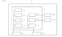
図2は,センシングコントローラー(SC)3の機能ブロック図である。図2に示されるように,センシングコントローラー3は,入力部7と,センサー制御部9と,出力部11とを有する。
FIG. 2 is a functional block diagram of the sensing controller (SC) 3. As shown in FIG. 2, the
入力部7は,1又は複数のセンサー5a,5b,5c,5dから,センシング情報を含む送信情報を受取る機能ブロックである。この送信情報は,1又は複数のセンサーのうちのあるセンサーが観測したセンシング情報,及びセンサー自身に関する情報のいずれか又は両方を含んでいる。センシング情報は,信号に関する数値(瞬間的なエネルギー値とその統計値)を示すソフト情報か,又はハード情報(バイナリー情報)を含んでいる。センサー制御部9は,1又は複数のセンサーへ送る制御指令を求める機能ブロックである。出力部11は,1又は複数のセンサーへ制御指令を出力する機能ブロックである。
The input unit 7 is a functional block that receives transmission information including sensing information from one or
センサー制御部9は,センサー決定ブロック13と,経路決定ブロック15と,制御指令ブロック17とを含む。センサー決定ブロック13は,入力部7から入力された送信情報のセンシング情報を分析して(又は他のブロックが分析した分析結果を用いて),センシングを行うセンサーを決定する機能ブロックである。経路決定ブロック15は,センシングを行うことが決定されたセンサーからセンシングコントローラー3へセンシング情報が伝達される経路を決定する機能ブロックである。制御指令ブロック17は,決定したセンサー及び経路に関する情報に基づいて,1又は複数のセンサーへ送る制御指令を求める機能ブロックである。この制御指令には,センシングを行うセンサーに関する情報や,センシング情報が伝達される経路に関する情報が含まれる。なお,この制御指令は,センシングを行わないセンサーに関する情報をさらに含むものであってもよい。
The
上記の構成を採用するため,本発明のコグニティブエンジン1は,以下のように動作する。すなわち,入力部7が,1又は複数のセンサー5a,5b,5c,5dから,センシング情報を含む送信情報を受取る。次に,センサー制御部9が,送信情報に含まれるセンシング情報を用いて,1又は複数のセンサー5a,5b,5c,5dへ送る制御指令を求める。そして,出力部11が,1又は複数のセンサー5a,5b,5c,5dへ制御指令を出力する。その後,1又は複数のセンサー5a,5b,5c,5dにおけるそれぞれのセンサーは,制御指令に従って,センシングを行うか又はセンシングを行わない。また,それぞれのセンサーは,制御指令における経路に従って,センシング情報を入力部7へと伝達する。
In order to employ the above configuration, the
本発明のコグニティブエンジン1の好ましい態様は,センサー制御部9が,さらに,品質評価ブロック19を有するものである。品質評価ブロック19には,センシング情報が入力部7を介して入力される。そして,品質評価ブロック19は,センシング情報の品質を評価する。具体的には,品質評価ブロック19は,スペクトラムセンサー5側(ユーザーチャンネル)に,ノイズ,干渉,シャドーイング,及びフェージングなどの悪い要因が発生しているかどうかを判断することで,センシング情報の品質の評価を行う。そして,このコグニティブエンジン1のセンサー決定ブロック13は,センシング情報の品質に関する情報を用いて,センシングを行うセンサーを決定する。よって,このコグニティブエンジン1は,センシング品質の悪い情報をフィルタリングによって除いて,センシング品質の良い情報を集約できる。つまり,コグニティブエンジン1は,複数のセンサーの中から,センシングに優れたセンサーを特定することができる。
In a preferred embodiment of the
本発明のコグニティブエンジン1の好ましい態様は,センサー自身に関する情報が,当該センサーの電力消費量に関する情報を含むものである。電力消費量に関する情報は,電源のバッテリー残量を数値化したものであってもよい。これによって,センサーの電力消費量に関する情報がコグニティブエンジン1に入力されるため,コグニティブエンジン1は,たとえば,電力消費量が少なくなるようにセンサーを選択することができる。また,電力消費量が少なくなるようにセンシング情報を伝達する経路を求めることができる。
In a preferred embodiment of the
本発明のコグニティブエンジン1の好ましい態様では,センシング情報が伝達される経路が,あるセンサーから他のセンサーを経て,前記入力部7へセンシング情報が伝達される経路を含むものである。ところで,従来のコグニティブエンジンを含む無線通信システムでは,単に,各センサーがコグニティブエンジンに直接センシング情報を伝達していた。しかし,コグニティブエンジンを搭載した端末から遠くにあるセンサーは,近くにあるセンサーにセンシング情報を伝達させる方ができれば,電力消費を抑えることが可能となる。そこで,本発明では,センシング情報が伝達される経路が,あるセンサーから他のセンサーを経て,入力部7へセンシング情報が伝達される経路を含むようにし,そして,その経路を選択することで,センサー間のセンシング情報の伝達を可能にしている。これにより,電力消費を抑えることができる。
In a preferred embodiment of the
本発明のコグニティブエンジン1の好ましい態様は,センシングコントローラー3が,さらに,優先順位ブロック21を有するものである。優先順位ブロック21は,センシングコントローラー3を有するコグニティブエンジン1の優先順位に関する情報を得るための機能ブロックである。この態様のコグニティブエンジン1では,出力部11が優先順位に関する情報を出力する。この出力を受けたセンサーは,優先順位に関する情報に従って,アクセスするコグニティブエンジン1を決めることになる。これにより,1又は複数のセンサー5a,5b,5c,5dにおけるそれぞれのセンサーは,コグニティブ無線通信領域内に複数のコグニティブエンジンが含まれている場合,優先順位に関する情報に従って,複数のコグニティブエンジンのうち,あるコグニティブエンジンの入力部7へ最初にセンシング情報を伝達する。具体例を挙げると,優先順位に関する情報をフラグで示すこととし,フラグがON(つまり優先順位が最高)であれば,センサーからコグニティブエンジン1へのアクセスが許容され,フラグがOFF(つまり優先順位が最低)であれば,センサーからコグニティブエンジンへのアクセスが禁止される。
In a preferred embodiment of the
本発明のコグニティブエンジン1の好ましい態様は,センサー制御部9が,さらに,センサー判断ブロック25を有する。センサー判断ブロック25は,センシング情報(又は送信情報内に含まれる他の情報)から,当該センシング情報を送信したセンサーがコグニティブエンジン1からの指令に基づいて動作するセンサーであるかどうかを判断する機能ブロックである。あるセンサーが,コグニティブエンジン1からの指令に基づいて動作するセンサーではないと判断された場合,そのセンサーは,従来のコグニティブ無線通信用のセンサーであるとコグニティブエンジン1によって識別される。これにより,従来のコグニティブ無線通信用のセンサーと本発明のコグニティブ無線通信用のセンサーとを区別することができる。この態様のコグニティブエンジン1は,センサー判断ブロック25における判断結果を用いて,センシング情報が伝達される経路を決定する。すなわち,従来のセンサー(レガシーセンサー)は,一方的にセンシング情報をコグニティブエンジンへ送信するだけであった。本発明のセンサーは,他のセンサーにもセンシング情報を転送できるように構成されている(後述)。また,ゲートウェイとして機能するセンサーに,複数のセンサーからのセンシング情報を集約し,ゲートウェイからコグニティブエンジン1へと集約したセンシング情報を伝達するように構成することもできる。よって,この態様のコグニティブエンジン1によれば,本発明の制御指令に従って動作できるセンサーを把握して,把握したセンサーによる最適な経路を決定できる。
In a preferred embodiment of the
本発明のコグニティブエンジン1の好ましい態様は,センサー制御部9がセンサー電力調整ブロック27を有する。センサー電力調整ブロック27は,入力部7から入力されたセンシング情報を分析して(又は他のブロックが分析した分析結果を用いて),センサーの電力を調整する指令を求める機能ブロックである。そして,センサーの電力を調整する指令は,センシングを行わないセンサーの電力を小さくする指令,及びセンシングを行うセンサーの電力を大きくする指令,のいずれか又は両方を含む。なお,センシングを行わないセンサーの電力を切り,センシングを行うセンサーの電力を入れ続けるような指令であってもよい。これにより,電力消費量を軽減できる。
In a preferred embodiment of the
本発明のコグニティブエンジン1の好ましい態様は,センシングコントローラー3が,第1の情報フィルタリングブロック29aを有するものである。第1の情報フィルタリングブロック29aは,品質評価ブロック19が評価したセンシング情報の品質に関する情報を用いて,センシング情報を選択するための機能ブロックである。この態様のコグニティブエンジンは,複数のセンシング情報を受取った場合,センシング情報の品質が良くないものを除くことで,センシング特性を向上させることができる。
In a preferred embodiment of the
本発明のコグニティブエンジン1の好ましい態様は,センシングコントローラー3が,さらに,第2の情報フィルタリングブロック29bするものである。なお,この態様のコグニティブエンジン1は,先に説明した第1の情報フィルタリングブロック29aをも有するものであってもよい。そして,第2の情報フィルタリングブロック29bは,センサー判断ブロック25における判断結果を用いて,センシング情報を選択するための機能ブロックである。たとえば,センサー判断ブロック25が,あるセンサーが異常に電力を消費すると判断した場合,そのセンサーを使用しないように判断する。そして,第2の情報フィルタリングブロック29bは,たとえば,その電力を消費するセンサーの電源をOFFにする指令を出力する。これにより,コグニティブ無線通信システム全体の消費電力量を軽減できる。
In a preferred embodiment of the
なお,上記したコグニティブエンジン(CE)1の好ましい態様はそれぞれ任意に組み合わせて用いることができる。この場合,先に説明したそれぞれの技術的効果を奏するコグニティブエンジン1を得ることができる。また,上記CE1は,端末や基地局に搭載されるとしたが,これに代えて,CE1の一部を端末本体とは別体となるようにしてもよい。すなわち,CE1の一部を遠隔操作可能に構成してもよい。
The preferred embodiments of the above-described cognitive engine (CE) 1 can be used in any combination. In this case, the
上述したように,コグニティブエンジン(CE)1は,センシングを行うスペクトラムセンサー5を選択することができるようになっており,また,センシング情報を選ぶことができるようになっている。このため,キャリアセンス性能を高めることができる。そのため,CE1を含むコグニティブ無線通信システムでは,スペクトラムの利用効率を高めることができる。また,CE1がスペクトラムセンサー5を選択できるので,CE1は,スペクトラムセンサー5との間で,コグニティブ無線通信を確実に確立することができる。なお,CE1がスペクトラムセンサー5を制御できる限りにおいては,スペクトラムセンサー5は,従来のセンサー(レガシーセンサー)であってもよいが,この場合には,センシング情報プロセッサ(SIP)2を有することが好ましい。
As described above, the cognitive engine (CE) 1 can select the
また,上記CE1は,スペクトラムセンサー5の電力消費量を把握でき,スペクトラムセンサー5の電力を調整する指令を出すことができるようになっている。このため,スペクトラムセンサー5の電力消費量を軽減できる。さらに,CE1は,たとえば,スペクトラムセンサー5間でセンシング情報を伝達するようにセンシング情報の経路を制御できる。このため,このCE1を用いたコグニティブ無線通信システムでは,全てのスペクトラムセンサーがCE1に直接センシング情報を伝送しなくても良い。よって,センシング情報の伝送路長を軽減でき,このためコグニティブ無線通信システムの電力消費量を軽減できる。
The
次に,図3を用いて本発明のスペクトラムセンサー5を説明する。本発明のスペクトラムセンサー(Smart Spectrum Sensor:S3)は,コグニティブ無線通信に用いられる従来のセンサー(レガシーセンサー)を有する。このため,スペクトラムセンサー5は,従来のセンサーの全ての機能を有している。すなわち,スペクトラムセンサー5は,レガシーセンサーと同様,たとえば,プライマリーユーザーの存在など,特殊なラジオアクセス技術に基づいて通信条件を決定できる。さらに,スペクトラムセンサー5は,レガシーセンサーと同様,周囲のラジオ環境の変化を検出してその情報を提供できる。
Next, the
図3に示されるように,本発明のスペクトラムセンサー5は,センシング情報プロセッサ(SIP)2と,記憶ユニット31と,センシングユニット32と,コミュニケーションユニット33と,電源ユニット34とを有する。センシング情報プロセッサ(SIP)2は,共通のデータ構造となるように情報を加工する処理を行う情報処理部であり,また,必要に応じて,外部からの要求に応じた動作を行う場合もある。
As shown in FIG. 3, the
センシングユニット32は,コグニティブ無線通信に用いられるセンシング情報を検出するユニットである。このセンシングユニット32として,コグニティブ無線通信に用いられる公知のスペクトラムセンサーに用いられているセンシングユニットを用いることができる。また,このセンシングユニット32は,検出したセンシング情報をSIP2に入力する。
The
記憶ユニット31は,センシング情報を記録するとともに,コグニティブ無線通信に用いられる情報を記憶するユニットである。コグニティブ無線通信に用いられる情報には,制御プログラム,フォーマット形式,端末のアドレスなどの情報が含まれていても良い。そして,記憶ユニット31は,最新のセンシング情報などを他のクライアント(コグニティブエンジン1が搭載された端末やSIP2が搭載された端末)に送信するために用いられる。また,記憶ユニット31は,SIP2がスペクトラムやCE1への送信情報をモニタリングするためにも用いられる。このため,記憶ユニット31は,従来のセンサーよりも記憶容量が多い方が好ましい。これにより,たとえば,スペクトラムの長期間にわたる利用に適したスペクトラムセンサー5を提供できる。
The
コミュニケーションユニット33は,スペクトラムセンサー5に送信された情報(コグニティブエンジン1からの制御情報や他のスペクトラムセンサー5からの送信情報)を受取るとともに,センシング情報プロセッサ(SIP)2から出力された各種情報を送信するためのユニットである。
The
電源ユニット34は,電源を含み,当該電源からの電力をスペクトラムセンサー5の各ユニットに供給するユニットである。電源ユニット34は,センシング情報プロセッサ(SIP)2からの指令に応じて動作するように構成されている。
The
センシング情報プロセッサ(SIP)2は,第1のセンシング情報変換部36と,第2のセンシング情報変換部37と,送信先決定部38とを少なくとも含む。そして,本発明のスペクトラムセンサー5は,このSIP2を含むことによって,センシングコントローラー(SC)3からの指令に基づいてさまざまな動作(制御)を行うことができるように構成されている。たとえば,SIP2は,ある周波数帯についてのみセンシングを行うよう指令を受けた場合,その指令に従ってセンシング領域を限定することもできる。なお,センシングコントローラー(SC)3などの制御装置からの制御情報を判別する方法は,公知の方法を用いることができる。
The sensing information processor (SIP) 2 includes at least a first sensing
第1のセンシング情報変換部36は,センシングユニット32が検出したセンシング情報を,コグニティブエンジン(CE)1のセンシングコントローラー(SC)3へ送信するために,センシング情報を第1のフォーマットを用いて第1のセンシング情報に変換するための機能ブロックである。すなわち,第1のセンシング情報変換部36は,SC3からセンシング情報をSC3へ送信するような指令を受けた場合,センシング情報をSC3へ送信するためにあるフォーマット(符号化方式や特定のアドレスを付加する形式)に従って,センシング情報を変換する。なお,他のスペクトラムセンサーから受信したセンシング情報と,記憶ユニット31に記憶した最新のセンシング情報とを合わせる処理を行い,合わせたセンシング情報を変換し,変換して得られるセンシング情報を,第1のセンシング情報としてSC3へ送信しても良い。なお,第1のセンシング情報変換部36は,センシング情報を単に変換するだけでなく,必要な処理(たとえば,演算などのデータ処理やデータの追加)を施してもよい。これにより,送信すべきデータ量の削減を図ることができる。また,センサー間の通信路の通信品質が,センサーとCEとの間の通信路の通信品質よりも良い場合,センサー間で情報の送受信を行うことで,センシング品質の向上などを実現することができる。
The first sensing
第2のセンシング情報変換部37は,センシングユニット32が検出したセンシング情報を他のスペクトラムセンサーに送信するために,センシング情報を第2のフォーマットを用いて第2のセンシング情報に変換するための機能ブロックである。すなわち,本発明のスペクトラムセンサー5は,近接する他のスペクトラムセンサーを介して,センシング情報をSC3へ伝達することができる。この伝達経路は,たとえば,SC3からの指令に従って決められる。なお,第2のセンシング情報変換部37は,センシング情報を単に変換するだけでなく,必要な処理(たとえば,データ処理やデータの追加)を施してもよい。
The second sensing
送信先決定部38は,センシングコントローラー(SC)3からの制御指令に従って,センシングユニット32が検出したセンシング情報を,第1のセンシング情報又は第2のセンシング情報のいずれに変換するかを決定する機能ブロックである。具体的には,送信先決定部38は,SC3からの情報を復号化するデコーダ39を含み,デコーダ39が復号化した情報に含まれる制御指令を解析する。そして,送信先決定部38は,その制御指令に含まれるセンシング情報の送信先に従って,第1のセンシング情報変換部36及び第2のセンシング情報変換部37を制御する。これにより,第1のセンシング情報変換部36及び第2のセンシング情報変換部37のいずれかがセンシング情報の変換を行う。このようにして,SC3からの制御指令に従って,センシング情報を流通させることができる。なお,送信先決定部38は,SC3の制御指令に従って動作するとしたが,これに代えて,送信先決定部38は,センサー5の優先順位に従って,上記動作を行ってもよい。この場合,センサー5自身の優先順位に関する情報は,記憶ユニット31に格納されている。
The transmission
本発明の好ましい態様は,センシング情報プロセッサ(SIP)2が変換する情報に,さらにセンサー自身に関する情報が含まれるものである。すなわち,この態様のスペクトラムセンサー5は,スペクトラムセンサー5の電力消費量や位置などに関する情報をSC3に提供することができる。このような情報を得たSC3は,適切なスペクトラムセンサー5を選択し,またセンシング情報の経路を適切に決めることができることとなる。さらに,あるセンシング情報を得る際に,複数のスペクトラムセンサーに適切に分配できることとなる。
In a preferred embodiment of the present invention, the information converted by the sensing information processor (SIP) 2 further includes information on the sensor itself. In other words, the
センシング情報プロセッサ(SIP)2は,センシングユニット32が検出したセンシング情報を当該センシングユニット32から受取る。本発明のスペクトラムセンサー5は,先に説明したとおり,SIP2を有するため,センシング情報を近隣のペクトラムセンサー5から受取ることができる。そして,SIP2により集約したセンシング情報をセンシングコントローラーSC3へ出力することができる。
The sensing information processor (SIP) 2 receives sensing information detected by the
センシング情報プロセッサ(SIP)2は,SC3から指令を受取り,その指令に従った動作を行うことができる。また,SIP2は,クライアント(端末)の優先順位を解析する優先順位解析部を有していることが好ましい。この場合,記憶ユニット31には,クライアント(端末)の優先順位に関する情報がデータベースとして格納されている。これにより,SIP2は,クライアントの優先順位を解析できる。そして,このSIP2は,解析した優先順位に従って,どのクライアントにセンシング情報を提供するかを決めることができる。これにより,たとえば,コグニティブ無線通信領域内に存在する複数の端末において,優先順位の低い端末から,優先順位の高い端末へと情報を順次提供することができる。
The sensing information processor (SIP) 2 can receive a command from the
また,センシング情報プロセッサ(SIP)2は,スペクトラムセンサー5をレガシーセンサーとして機能させるか又はセンシング情報プロセッサ(SIP)2を有するセンサーとして機能させるかを切替えるスイッチ手段を有することが好ましい。これにより,たとえば,スペクトラムセンサー5をレガシーセンサーとして機能させることで,センシング情報プロセッサ(SIP)2で実現可能な機能の一部を停止させることができる。このように,センシング情報プロセッサ(SIP)2がスイッチ手段を有することで,スペクトラムセンサー5は,SC3から受取った指示に応じた動作を確実に行うことができるようになる。
In addition, the sensing information processor (SIP) 2 preferably has switch means for switching whether the
スペクトラムセンサー5は,コグニティブ無線通信端末などの端末や他のセンサーと情報を交換できるように構成されている。情報交換に関する動作は,コグニティブエンジン(CE)1のセンシングコントローラー(SC)3によって制御される。SC3によって制御される動作は,ある地理的エリアに含まれる複数のセンサー間で分散されてもよい。つまり,SC3は,ある動作を複数の動作に割当て,それら複数のセンサーにそれぞれの動作をするように指示をしてもよい。そして,たとえば,それぞれのセンサーにより検出されたセンシング情報をあるセンサーが集約して,SC3へ伝えるようにしても良い。このようにして,行わなければならないセンシング作業を複数のセンサーに分散させることができる。
The
スペクトラムセンサー5と端末とが交換する情報には,シグナリングコントロール情報が含まれる。シグナリングコントロール情報は,センサー5のセンシングアクティビティーを制御するための情報である。スペクトラムセンサー5と端末とが交換する情報には,さらにセンシング情報が含まれる。さらに,たとえばセンサー5のコミュニケーション能力が十分でない場合など,あるセンサー5から直接センシング情報を集めることができない場合は,近くにあるセンサーがそのセンサー5に協力(補助)することで,センシング情報を集めることができる。具体的には,コミュニケーション能力が十分にあるセンサーは,コミュニケーション能力が十分でないセンサー5から情報を集め,集めた情報と,センサー自身の情報とを合わせて,SC3に送信する。
Information exchanged between the
また,スペクトラムセンサー5は,SC3から制御されていない間,自身の判断で動作を行うように構成されていることが好ましい。この場合,たとえば,記憶ユニット31には,さらに,センサー5自身の優先順位に関する情報が格納されており,SIP2は,他のセンサーのSIPとの間で,優先順位に関する情報の交換を行うことで,他のセンサーとの優先順位の違いを把握するように構成される。これにより,スペクトラムセンサー5は,優先順位が異なる他のセンサーとの間で,優先順位に応じた動作を行うことが可能となる。たとえば,複数のセンサーが同時にある1つのコグニティブエンジン(CE)1へアクセスしようとした場合,優先順位の高いセンサーが先にCE1へアクセスし,優先順位の低いセンサーは,優先順位の高いセンサーがCE1へのアクセス中に,アクセスを中断するか又は他のセンサーと情報の交換を行う。また,たとえば,コグニティブエンジン1を搭載した端末とSIP2を搭載した端末とが同時に,1つのセンサー5にセンシング情報を含む送信情報の送信を要求した場合,センサー5は,自身の優先順位に応じて一方の端末(クライアント)へ先にセンシング情報を送信する。具体的には,センサー5の優先順位が相対的に低く設定されている場合,SIP2を搭載した端末へ先にセンシング情報を送信し,その後,必要に応じて,コグニティブエンジン1を搭載した端末へセンシング情報を送信し,逆に,自身の優先順位が高い場合には,先にコグニティブエンジン1を搭載した端末へセンシング情報を送信する。このように,スペクトラムセンサー5が自身の判断で動作する場合にも,SIP2の送信先決定部38が用いられる。すなわち,送信先決定部38は,優先順位に従って動作するように構成されている。
Moreover, it is preferable that the
上述したように,スペクトラムセンサー5は,センシング情報プロセッサ(SIP)2を有するので,コグニティブエンジン1が搭載された端末や,他のスペクトラムセンサーとの間で,無線ネットワークを容易に構築することができる。これにより,センシング情報などを効率的に共有できる。
As described above, since the
続いて,ネットワークについて詳細に説明する。まず,コグニティブコグニティブエンジン(CE)1が搭載された端末と,センシング情報プロセッサ(SIP)2が搭載されたスペクトラムセンサー5との間で構築される無線ネットワークについて説明する。図4〜図6は,端末とスペクトラムセンサー5との接続状況の例を説明するための図である。
Next, the network will be described in detail. First, a wireless network constructed between a terminal equipped with a cognitive cognitive engine (CE) 1 and a
図4は,ひとつの端末に複数のスペクトラムセンサー5a,5b,5c,5dからセンシング情報が直接入力されるモードを示す図である。図4に示されるモードは,いわゆるマルチプルセンシングモードである。具体的には,コグニティブエンジン1は,複数のセンサー5a,5b,5c,5dからセンシング情報を受取り,集約する。そして,コグニティブエンジン1は,受取ったセンシング情報を解析して,利用できるスペクトラム(周波数帯や時間帯)を分析する。このマルチプルセンシングモードは,従来と同様ではあるが,各センサーがSIP2を備えているため,コグニティブエンジン1に適したフォーマットで送信情報が送信される。このため,コグニティブエンジン1は,迅速にセンシング情報を集約することができ,その結果,センシング情報の変化が少ない期間に,各センサーに制御指令を送信することができる。また,コグニティブエンジン1は,センシング情報だけでなく,各センサーのさまざまな情報を集約して,比較することができる。
FIG. 4 is a diagram illustrating a mode in which sensing information is directly input from a plurality of
図5は,センシングコントローラー(SC)3が,利用するスペクトラムセンサー5を選択した場合のモードの一例を示す図である。図5に示されるモードは,コグニティブエンジン1が,選択したスペクトラムセンサーからセンシング情報を受取るモードであって,あるセンサーを使用しない場合を含むモードである。
FIG. 5 is a diagram illustrating an example of a mode when the sensing controller (SC) 3 selects the
図5に示すモードを実現するために,事前に,センシングコントローラー(SC)3は,複数のセンサー5a,5b,5c,5dから接続開始要求を受取り,接続開始要求に含まれる情報(センシング情報など)に基づいて,たとえば,各センサーのセンシング状況及び電力消費量を評価している。そして,その評価結果に応じて,センシングコントローラー(SC)3は,たとえば,センサー5bを使用しない旨を決定するとともに,センシング情報を伝達する経路として,図5の矢印に示される経路でセンシング情報を提供するように決定する。
In order to realize the mode shown in FIG. 5, the sensing controller (SC) 3 receives connection start requests from the plurality of
その場合,そのような決定をしたSC3は,各センサー5a,5b,5c,5dのSIP2a,2b,2c,2dに対し,センシングの要否,及びセンシング情報の経路に関する情報を含む制御指令を送信する。
In this case, the
すると,図5に示すように,その制御指令を受けたSIP2a,2b,2c,2dのうち,SIP2a,2c,2dはセンシングを行い,一方で,SIP2bはセンシングをやめる。また,センシング情報は,制御指令に含まれる経路に関する情報に従って,SIP2d,2c,2aの順で,つまり,SIP2d,2c,2aという経路で,SC3まで伝達される。つまり,センシングコントローラー(SC)3は,SIP2dのところで集約されたセンシング情報を受取る。
Then, as shown in FIG. 5, among the
上述したように制御することで,図5に示した例では,それぞれのセンサー5c,5dが個別にSC3へセンシング情報を直接提供しないようにしている。つまり,センシングコントローラー(SC)3は,各センサーに制御指令を送信することで,センシング情報が,所定の時間順で,所定の経路に沿ってSC3まで伝達されるように制御することができる。その結果,このSC3を含むコグニティブ無線通信システムでは,複数のセンサーによるセンシング作業を分担でき,しかも,全てのセンサーが個別にSC3に直接センシング情報を提供(伝送)しなくて良い。このため,センシング情報の伝送路長を軽減でき,結果として,電力消費量も軽減できる。また,図5に示すように,センシング情報を伝達する経路を1種類に定めることにより,経路の下流側のセンサーは,上流側のセンサーが集約したセンシング情報を受取ることとなる。これにより,SC3は,複数のセンサーからの多数のセンシング情報を一度に受信することがなくなり,その結果,通信障害などが起こりにくくなる。
By controlling as described above, in the example shown in FIG. 5, each
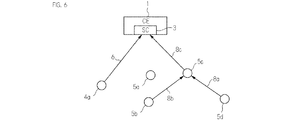
図6は,センシングコントローラー(SC)3が,利用するスペクトラムセンサー5を選択した場合のモードの他の例を示す図である。図6に示されるモードは,コグニティブエンジン1が,選択したスペクトラムセンサーからセンシング情報を受取るモードであって,さらに,あるセンサーからもセンシング情報を受取る場合を含むモードである。
FIG. 6 is a diagram showing another example of the mode when the sensing controller (SC) 3 selects the
図6では,従来のセンサーであるレガシーセンサー4aもコグニティブ無線通信領域(エリア)内に配置されている。レガシーセンサー4aは,上述したSIP2のようなプロセッサを有さないので,SC3からの指令に従って動作することができず,ひたすらセンシング情報をSC3へと送信する。図6において,矢印6は,レガシーセンサー4aからセンシング情報がSC3へ出力されることを示している。
In FIG. 6, the
また,図6に示す例では,センサー5cがゲートウェイとして機能する。すなわち,センサー5d及び5bは,センシング情報をセンサー5cへ出力する(矢印8a,8b)。これらのセンサー5d及び5bは,センシング情報をSC3へ直接送信できないセンサーであってもよい。これにより,ゲートウェイとして機能するセンサー5cのSIPSIP2cには,センシング情報が集約することになる。さらに,このセンサー5cは,センサー5d及び5bから入手したセンシング情報を自らのセンシング情報と合わせて,SC3へと出力する(矢印8c)。このようにして,センシングコントローラー(SC)3は,センサー5cから,局所的に集約されたセンシング情報と,ゲートウェイ自身のセンシング情報とを受取る。また,このセンサー5cは,必要に応じて,センシングコントローラー(SC)3からの制御指令をセンサー5d及び5bへ転送する。
In the example shown in FIG. 6, the
このように,本発明のコグニティブ無線通信システムでは,スペクトラムセンサー5同士がセンシング情報のやり取りを行うことができる。そして,このように,センシング情報をやり取りすることで,スペクトラムセンサー5間の協働的なセンシングが活性化される。特に,コグニティブ無線通信システムにおいてゲートウェイとなるスペクトラムセンサー5を設ける(設定する)ことによって,互いに近くにあるスペクトラムセンサー5同士でセンシング情報のやり取りを行うことができる。これにより,遠くにある基地局へのアップリンクに起因する情報の伝送量の増大を軽減できるとともに,各スペクトラムセンサー5の電力消費量を軽減できる。さらには,ゲートウェイとなるスペクトラムセンサー5が,センシング情報を集約したり,制御情報を転送したりする。つまり,ゲートウェイとなるスペクトラムセンサー5は,センシングコントローラー(SC)3の一部の機能を担っている。これにより,センシングコントローラー(SC)3と直接情報のやり取りをできないセンサーをも無線ネットワークに組み入れることができる。なお,ゲートウェイとなるスペクトラムセンサー5は,センシング情報を集約する機能だけを担ってもよいし,制御情報を転送する機能だけを担ってもよい。
Thus, in the cognitive radio communication system of the present invention, the
また,本発明のコグニティブ無線通信システムでは,上述したように,スペクトラムセンサー5とセンシングコントローラー(SC)3との間で協働させることが可能である。そして,スペクトラムセンサー5やセンシングコントローラー(SC)3に,各スペクトラムセンサー5を制御する各手段を上述したように設けることで,各スペクトラムセンサー5のタスクやセンシングの時間の制御が容易となる。これにより,コグニティブ無線通信システムにおけるセンシングの効率を高めることができる。
In the cognitive radio communication system of the present invention, as described above, the
ここで,図5に示した場合と図6に示した場合とで,センシング情報の集約の違いは,図6に示すセンサー5c(ゲートウェイ)が他のセンサーからのセンシング情報を個別に集約するのに対して,図5に示したセンサー5aは,他のセンサーが集約した情報を受取ることにある。前者は,センシング情報を集約するのに時間がかからないという点で有効であり,後者は,あるセンサーがSC3から遠い場合(又は遠ざかるような移動をする場合)であってもコグニティブ無線通信が可能となる点で有効である。
Here, the difference in aggregation of sensing information between the case shown in FIG. 5 and the case shown in FIG. 6 is that the
上述したように,本発明のコグニティブ無線通信システムでは,スペクトラムセンサー5に,センシング情報プロセッサ(SIP)2を設け,コグニティブエンジン1にセンシングコントローラー(SC)3を設けることで,それらが搭載された端末間で無線ネットワークを構築している。つまり,端末間には,インターフェイス4が存在していると云える(図1参照)。このようなインターフェイスには,3種類が考えられる。すなわち,SC3とSIP2との間で通信を行うためのインターフェイス(SC−Sインターフェイス)と,SC3同士間で通信を行うためのインターフェイス(S−Sインターフェイス)と,SIP2同士間で通信を行うためのインターフェイス(SC−SCインターフェイス)とがある。
As described above, in the cognitive radio communication system of the present invention, the
そこで,このようなインターフェイスを端末に設けるインターフェイス装置として説明する。したがって,本発明のインターフェイス装置は,上述した構成要素と同等の機能又は一部の機能を有することとなる。なお,以下の説明は,上述した3種類のインターフェイスのうち,主に,SC−Sインターフェイス用のインターフェイス装置についてのものであるが,S−Sインターフェイス用のインターフェイス装置についても適用可能であるし,SC−SCインターフェイス用のインターフェイス装置についても適用可能である。 Therefore, the interface device provided with such an interface in the terminal will be described. Therefore, the interface device of the present invention has a function equivalent to or a part of the functions described above. The following description is mainly about the interface device for the SC-S interface among the above-described three types of interfaces, but it can also be applied to the interface device for the SS interface. The present invention can also be applied to an interface device for SC-SC interface.
本発明のインターフェイス装置は,上記のように,スペクトラムセンサー5同士がセンシング情報のやり取りを行い,かつセンシングコントローラー(SC)3とスペクトラムセンサー5とが情報のやり取りを行うために用いられる。また,このインターフェイス装置は,コグニティブエンジン(CE)1が複数配置されている場合,それらのセンシングコントローラー(SC)3間で情報のやり取りを行うためにも用いることも可能である。
As described above, the interface apparatus of the present invention is used for the
本発明では,コグニティブエンジン(CE)1のSC3とスペクトラムセンサー5のセンシング情報プロセッサ(SIP)2との間で共通のインターフェイス(SC−Sインターフェイス)が確立されている。そのために,SC3とセンシング情報プロセッサ(SIP)2とは,それぞれ,以下のインターフェイス装置を有している。すなわち,各インターフェイス装置は,スペクトラムセンサー5の一部又はコグニティブエンジン(CE)1の一部を構成するものである。そして,このインターフェイス装置は,ハードウェアにより実装されても良いし,ソフトウェアにより実装されても良いし,それらの組み合わせで実現されてもよい。
In the present invention, a common interface (SC-S interface) is established between the
具体的には,本発明のCE1及びスペクトラムセンサー5は,それぞれ,インターフェイス装置の構成要素として,入力部,出力部,制御部(SC3,SIP2),演算部,及び記憶部を有しており,各構成要素は,バスなどで情報の授受を行うことができるようにされている。なお,上記構成要素に対応する機能がソフトウェアにより実装される場合は,その機能をハードウェアにより実現するための制御プログラムが記憶部のメインメモリに格納されている。そして,入力部から所定の情報が入力された場合,制御部は,上記メインメモリから制御プログラムを読み出して,適宜記憶部から情報を読み出し,演算部に対して各種演算を行うように指令を出す。このようにして,所定の演算処理を行うことができる。なお,インターフェイス装置の各部は,CE1が有する機能ブロック,又はスペクトラムセンサー5が有する機能ブロックに対応するものであってもよいし,それら機能ブロックとは別のものであってもよい。
Specifically, the
インターフェイス装置は,接続様式付加手段41を有する。接続様式付加手段41は,スペクトラムセンサー5の接続様式(コネクションタイプ又はセンシングモード)に関する情報を,当該インターフェイス装置から出力される情報に含ませる(載せる)ための手段である。ここで,スペクトラムセンサー5の接続様式には,ポイントトゥーポイント,ピアトゥーピア,及びポイントゥーマルチポイントなどがある。ポイントトゥーポイントは,あるセンシングコントローラー3が,あるひとつのスペクトラムセンサー5からセンシング情報を受取る接続形式である(たとえば,図5参照)。また,ポイントゥーマルチポイントは,あるセンシングコントローラー3は,複数のスペクトラムセンサー5からセンシング情報を受取る接続形式である(たとえば,図4参照)。そして,ピアトゥーピアは,スペクトラムセンサー5間でセンシング情報を送信又は受信する接続形式である(たとえば,後述する図8参照)。なお,図6に示した例では,コグニティブエンジン1とゲートウェイとして機能するスペクトラムセンサー5cとの間の接続形式がポイントトゥーポイントである。また,ポイントトゥーポイントには,図6におけるコグニティブエンジン1とレガシーセンサー4aとの間の接続形式も含まれるとしてもよい。
The interface device has connection mode adding means 41. The connection mode adding means 41 is a means for including (loading) information related to the connection style (connection type or sensing mode) of the
ここで,インターフェイス装置から出力される情報としては,センシングコントローラー(SC)3から,スペクトラムセンサー5のセンシング情報プロセッサ(SIP)2へ送信する制御指令や,SIP2からSC3へ送信される,センシング情報を含む送信情報などが考えられる。しかし,SIP2は,基本的には,SC3からの制御指令に応じて動作をするので,接続様式付加手段41は,SC3側のインターフェイス装置に設けられることが好ましい。この場合,接続様式に関する情報は,制御情報に含まれることになる。
Here, the information output from the interface device includes a control command transmitted from the sensing controller (SC) 3 to the sensing information processor (SIP) 2 of the
本発明のインターフェイス装置は,上記の構成を採用するので,接続様式付加手段41が,センシングコントローラー(SC)3から送信される情報に,スペクトラムセンサー5の接続様式(通信方式)に関する情報を送信情報に含ませる。次に,スペクトラムセンサー5のセンシング情報プロセッサ(SIP)2が,スペクトラムセンサー5の接続様式に関する情報が付加された送信情報を読み出す。そして,スペクトラムセンサー5は,読み出したスペクトラムセンサーの接続様式に関する情報を解読する。その後,スペクトラムセンサー5は,センシングコントローラー3が決定した相手にセンシング情報を送信する。
Since the interface apparatus of the present invention employs the above-described configuration, the connection mode adding means 41 transmits information related to the connection mode (communication method) of the
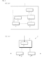
以下,さらに,インターフェイス装置に含まれると好ましい機能ブロックについて説明する。ただし,機能ブロックによっては,センシングコントローラー(SC)3側のインターフェイス装置に設けられることが好ましい場合と,スペクトラムセンサー5側のインターフェイス装置に設けられることが好ましい場合とがあり,また,場合によっては,双方に設けた方が好ましい場合もある。各場合については,適宜判断される。図7は,本発明のインターフェイス装置の構成を例示する図であり,図7(a)は,センシングコントローラー(SC)3側のインターフェイス装置の構成の一例を示す図であり,図7(b)は,スペクトラムセンサー5側のインターフェイス装置の構成の一例を示す図である。
In the following, functional blocks that are preferably included in the interface device will be described. However, depending on the functional block, there are a case where it is preferable to be provided in the interface device on the sensing controller (SC) 3 side, and a case where it is preferable to be provided in an interface device on the
本発明のインターフェイス装置の好ましい態様は,リンク状態付加手段42をさらに含む。リンク状態付加手段42は,出力される情報に,リンク状態についての情報を付加するための手段である。リンク状態についての情報は,(a)センシングコントローラー(SC)3とスペクトラムセンサー5とが,はじめて接続されるモード(初期化)にあるという旨の情報,(b)センシングコントローラー3がスペクトラムセンサー5に制御情報を送信するモードにあるという旨の情報,または,(c)センシングコントローラー3とスペクトラムセンサー5とが,センシング情報を交換するモードにあるという旨の情報を含む。これにより,このインターフェイス装置を含むコグニティブ無線通信システムは,リンク状態を把握して適切な制御を行うことができる。リンク状態付加手段42は,SC3が複数のセンサーを管理する場合には,SC3側のインターフェイス装置に設けられることが好ましい。しかし,ピアトゥーピア(センサートゥーセンサー)を可能にするためには,スペクトラムセンサー5側のインターフェイス装置にもリンク状態付加手段42を設けることが好ましい。
The preferred embodiment of the interface apparatus of the present invention further includes link state adding means 42. The link status adding means 42 is means for adding information about the link status to the output information. Information on the link state includes (a) information that the sensing controller (SC) 3 and the
本発明のインターフェイス装置の好ましい態様は,リンクの質付加手段43をさらに含む。リンクの質付加手段43は,出力される情報に,リンクの質についての情報を付加するための手段である。リンクの質とは,たとえば,あるセンシングコントローラー3とあるスペクトラムセンサー5とのリンクの質である。ここで,リンクの質についての情報は,通常,SC3側のインターフェイス装置にリンク状態付加手段42が設けられている場合であって,SC3とスペクトラムセンサー5との接続が開始される際にSC3によって評価されるものであるため,リンクの質についての情報は,SC3とスペクトラムセンサー5との接続開始後に得られる。このために,リンクの質についての情報には,未評価であることについての情報をも含んでも良い。このリンクの質についての情報を用いることで,このインターフェイス装置を含む端末は,そのリンクが妥当かどうかを判断できる。また,センシングコントローラー3は,複数のスペクトラムセンサー5とのリンクの質に関する情報を集約した場合,集約した情報を用いて適切なスペクトラムセンサー5を選択できる。
The preferred embodiment of the interface apparatus of the present invention further includes a link
本発明のインターフェイス装置の好ましい態様は,インターフェイス識別情報付加手段44をさらに含む。インターフェイス識別情報付加手段44は,出力される情報に,インターフェイスの識別情報を付加するための手段である。すなわち,インターフェイスにもいくつかの種類がある場合がある。よって,インターフェイス識別情報付加手段44を有する端末は,どの方式のインターフェイスであるかを判断できる。なお,このインターフェイス識別情報については,全ての種類のインターフェイスにおいて共通のものとすることが好ましい。これにより,インターフェイスが扱うことができる形式にデータを変換する必要をなくすことができる。又は,インターフェイス識別情報付加手段44を含む端末が,コグニティブ無線通信領域内において,アクティブなインターフェイスに対して固有のIDを設定してもよい。これにより,全てのインターフェイスを個別に管理することができる。さらには,全てのインターフェイス装置がインターフェイス識別情報付加手段44を有していてもよい。この場合,インターフェイス装置から出力されるルーティングプロトコルパケットに含まれるソースIDをインターフェイスの識別情報として用いることができる。
The preferred embodiment of the interface device of the present invention further includes interface identification
本発明のインターフェイス装置の好ましい態様は,スペクトラムセンサー識別情報付加手段45をさらに含む。スペクトラムセンサー識別情報付加手段45は,出力される情報に,スペクトラムセンサー5の識別情報を付加するための手段である。したがって,スペクトラムセンサー5側のインターフェイス装置にスペクトラムセンサー識別情報付加手段45を設けることが好ましい(図7(b)参照)。この態様のインターフェイス装置では,たとえば,全てのスペクトラムセンサーの各々に固有の識別情報(センサーID)がある。このスペクトラムセンサー5の識別情報が付加されるため,SC3(センサー判断部25)が搭載された端末では,スペクトルセンサー5の個性や特性を把握できる。スペクトラムセンサー5の識別情報は,無線ネットワーク上で重要なセンサー(たとえば,ゲートウェイとして機能するセンサー)を特定するための情報であってもよい。このような情報は,上記ルーティングプロトコルパケットに付加情報として容易に付加することができる。これにより,接続形式に応じてどのように機能するセンサーであるのかを容易に特定することができる。なお,スペクトラムセンサー識別情報付加手段45をSC3側のインターフェイス装置に設けてもよい(図7(a)参照)。この場合,SC3は,複数のスペクトラムセンサーの識別情報を集約した後で,あるスペクトラムセンサーを介して他のスペクトラムセンサーに制御指令を送る際に,当該他のスペクトラムセンサーを特定する情報を付加することができることになる。
The preferred embodiment of the interface device of the present invention further includes a spectrum sensor identification
本発明のインターフェイス装置の好ましい態様は,電力状況付加手段46をさらに含む。電力状況付加手段46は,出力される情報に,電力状況に関する情報を付加するための電力状況付加手段をさらに含む。たとえば,スペクトラムセンサー識別情報付加手段45及び電力状況付加手段46の双方が設けられている場合,スペクトラムセンサー5の識別情報(センサーID)とともにその電力状況(消費量や残量)に関する情報を把握できるので,この情報を受取ったセンシングコントローラー(SC)3は,使用するセンサー5を適切に選択できる。なお,スペクトラムセンサー識別情報付加手段45が設けられていないインターフェイス装置に,電力状況付加手段46を設けてもよい。この場合,電力状況付加手段46は,電力状況に関する情報として,電力の残量に関する情報のみを付加するように構成してもよい。これにより,この情報を受取ったセンシングコントローラー(SC)3は,電力の残量が少ないセンサー5を使用しないように選択できる。
The preferred embodiment of the interface device of the present invention further includes power
本発明のインターフェイス装置の好ましい態様は,スペクトラムセンサーエリアコード付加手段47をさらに含む。スペクトラムセンサーエリアコード付加手段47は,出力される情報に,スペクトラムセンサー5のエリアコードを付加するための手段である。ここで,スペクトラムセンサーエリアコードは,コグニティブ無線通信領域内の位置を特定するための情報(たとえば,基地局からの距離と方角を示す情報)であってもよいし,コグニティブ無線通信領域とは無関係の地理的な情報(たとえば,GPSによって定まる位置情報)であってもよい。このようにエリアコードを付加できるので,適切にエリアを把握することができ,そのエリアに即したコグニティブ無線通信を達成できる。
The preferred embodiment of the interface apparatus of the present invention further includes a spectrum sensor area
本発明のインターフェイス装置の好ましい態様は,スペクトラムセンサーの質付加手段48をさらに含む。スペクトラムセンサーの質付加手段48は,出力される情報に,スペクトラムセンサー5の質に関する情報を付加するための手段である。スペクトラムセンサー5の質に関する情報は,たとえば,良い,悪い,又は未評価というように表される。そして,この情報を受取ったセンシングコントローラー(SC)3は,スペクトラムセンサー5の質に応じて,使用するセンサー5を適切に選択できることとなる。
The preferred embodiment of the interface apparatus of the present invention further includes a spectrum sensor
本発明のインターフェイス装置の好ましい態様は,コスト付加手段49をさらに含む。コスト付加手段49は,出力される情報に,あるインターフェイスを介して情報を送信した場合のコストに関する情報を付加するための手段である。コストに関する情報は,たとえば,スペクトラムセンサー5がセンシングコントローラー(SC)3に送信したときのコストの総額を示すものであってもよいし,他のセンシングコントローラー(SC)3に送信したときと比較したときにおけるコストがかかる順序を示すものであってもよい。さらに,このコストに関する情報には,スペクトラムセンサー5が,あるセンシングコントローラー3へセンシング情報を提供した場合の消費電力に関する情報や,使用する周波数帯に関する情報が含まれていても良い。なお,コストに関する情報は,コグニティブエンジン1とスペクトラムセンサー5との間の距離によって変えることが好ましい。そして,この情報を受取ったコグニティブエンジン1は,スペクトラムセンサー5から受取ったコストに関する情報に従って,使用するセンサー5を適切に選択することとなる。
The preferred embodiment of the interface device of the present invention further includes
本発明のインターフェイス装置の好ましい態様は,センシング情報付加手段50をさらに含む。センシング情報付加手段50は,出力される情報に,センシング情報を付加するための手段である。したがって,このセンシング情報付加手段50は,少なくとも,スペクトラムセンサー5側のインターフェイス装置に設ける必要がある。なお,上記した各種情報は,あるフレームのペイロードに含まれるようにしてもよい。そして,上記のいずれか又は2つ以上の情報を含むようなペイロード形式を設計し,そのフォーマットにしたがって,情報の授受を行うことが好ましい。
The preferred embodiment of the interface device of the present invention further includes sensing
本発明のインターフェイス装置の好ましい態様は,エンジン優先順位情報付加手段51をさらに含む。エンジン優先順位情報付加手段51は,出力される情報に,コグニティブエンジン1の優先順位に関する情報を付加するための手段である。この優先順位に関する情報は,コグニティブ無線通信領域内に配置されている複数のコグニティブエンジンのうち,スペクトラムセンサー5がどのコグニティブエンジンと優先的に通信を行うのかを示す情報であり,たとえば,数字で表される。なお,各コグニティブエンジン1は,送信先であるスペクトラムセンサー5に関する情報や,状況(リンクの状況,電力状況,コスト,距離など)によって優先順位を変えてもよい。ここで,優先順位は,複数のコグニティブエンジン1が,事前に,SC−SCインターフェイスを介して互いに通信を行うことで決められることが好ましい。そして,この情報を受取ったスペクトラムセンサー5は,優先順位に関する情報に従って,複数のコグニティブエンジン1の中から最初にインターフェイスを確立するコグニティブエンジンを決めることとなる。
The preferred embodiment of the interface device of the present invention further includes engine priority
本発明のインターフェイス装置の好ましい態様は,センサー優先順位情報付加手段52をさらに含む。センサー優先順位情報付加手段52は,出力される情報に,スペクトラムセンサー5の優先順位に関する情報を付加するための手段である。この優先順位に関する情報は,コグニティブ無線通信領域内に配置されている複数のスペクトラムセンサーのうち,どのスペクトラムセンサーが他のクライアント(SC3又は他のセンサー)と優先的に通信を行うのかを示す情報であり,たとえば,数字で表される。なお,各スペクトラムセンサー5は,送信先であるクライアントに関する情報や,状況(リンクの状況,電力状況,コスト,距離など)によって優先順位を変えてもよい。ここで,優先順位は,複数のスペクトラムセンサー5が,事前に,S−Sインターフェイスを介して互いに通信を行うことで決められることが好ましい。そして,この情報を受取ったクライアントは,優先順位に関する情報に従って,複数のスペクトラムセンサーの中から最初にインターフェイスを確立するスペクトラムセンサー5を決めることとなる。
The preferred embodiment of the interface device of the present invention further includes sensor priority
なお,SC3側に設けられるインターフェイス装置と,スペクトラムセンサー5側に設けられるインターフェイス装置とは,同じものであってもよいし,異なるものであってもよい。各インターフェイス装置には,必要に応じた機能ブロックが設けられる。ところで,スペクトラムセンサー5側に設けられるインターフェイス装置が,SC3側に設けられるインターフェイス装置と同じ場合,スペクトラムセンサー5のSIP2は,SC3と同等の機能を有することとなる。このようなスペクトラムセンサー5は,ゲートウェイとして機能させるセンサーとして最適である。
The interface device provided on the SC3 side and the interface device provided on the
次に,本発明のコグニティブ無線通信システムの評価について説明する。図8〜図11は,接続形式の概念を示す図である。なお,図8〜図11においては,1又は2つの端末(たとえば携帯端末)と,最大でも2つのスペクトラムセンサー5のみを描画している。しかしながら,これらに示される概念は多数の端末及びスペクトラムセンサー5を用いる場合にまで応用することができる。
Next, evaluation of the cognitive radio communication system of the present invention will be described. 8 to 11 are diagrams showing the concept of the connection format. 8 to 11, only one or two terminals (for example, portable terminals) and at most two
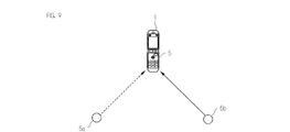
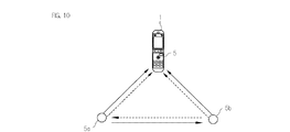
図8は,ピアトゥーピアセンシングの例を示す図である。図9は,協調センシングの例を示す図である。図10は,協働センシングの例を示す図である。図11は,ゲートウェイアシスト型センシングの例を示す図である。 FIG. 8 is a diagram illustrating an example of peer-to-peer sensing. FIG. 9 is a diagram illustrating an example of cooperative sensing. FIG. 10 is a diagram illustrating an example of cooperative sensing. FIG. 11 is a diagram illustrating an example of gateway-assisted sensing.
図8に示されるピアトゥーピアセンシングでは,センシング情報を,2つの端末の間で,つまりピアトゥーピア(P2P)で伝達する。この例では,それぞれの端末が,コグニティブエンジン1とスペクトラムセンサー5とを含んでおり,互いのインターフェイスは共通するものである。ここで,各端末が有するスペクトラムセンサー5は,他の端末がピアトゥーピアセンシングを行うことが可能なものであるかどうかを判断できるように構成されている。このようにピアトゥーピアで通信を行う場合,2つの端末は,互いに近接していることが好ましい。これにより,他の基地局などを介することなく,確実に2つの端末の間で通信が行われる。また,そのため,電力消費を抑制することができる。
In peer-to-peer sensing shown in FIG. 8, sensing information is transmitted between two terminals, that is, peer-to-peer (P2P). In this example, each terminal includes a
図9に示される協調センシングでは,たとえば2つのセンサー5a,5bがセンシング情報を協調してコグニティブ無線に転送する。協調センシングでは,端末がコモンインターフェイスを通じてすべてのセンサーから独立的にセンシング情報を取得し,それらを集約して信頼性のあるセンシング情報を生成する。このため,センサーの構成を簡略化することができる。
In the cooperative sensing shown in FIG. 9, for example, the two
図10に示される協働センシングでは,2つ(またはそれ以上)のセンサー5a,5bが協調して,携帯端末のコグニティブエンジン(CE)1にセンシング情報を提供する。状況に応じて,CE1は,たとえばセンサー5aに対して,センサー5aがそのセンサー5自体のセンシング情報を提供するように命令するだけでなく,その周りのセンサー5bと交流して情報(データ)を交換するよう命令する。これらの命令を受けたセンサー5aは,周りのセンサー5bと情報交換によって少なくとも当該センサー5bのセンシング情報を取得する。そして,そのセンサー5aは,自身に関する情報(センシング情報を含む)と周囲のセンサー5bのセンシング情報とを一緒にしてCE1に送信する。このようにすることで,携帯端末は,複数のセンサー5からの情報を効率的に集約することができる。
In the cooperative sensing shown in FIG. 10, two (or more)
図11に示されるゲートウェイアシスト型センシングでは,端末は,2つ(またはそれ以上)のセンサー5a,5bのうち,センサー5bをゲートウェイとして機能させるように選択する。これにより,センサー5bは,センサー5aからセンシング情報を受取った後に,受取ったセンシング情報を自身のセンシング情報とともに,端末へ送信する。このようにすることで,端末とセンサー5aとが情報のやり取りをできない場合であっても,端末は,センサー5bを介して,情報のやり取りを行うことができるようになる。
In the gateway assist type sensing shown in FIG. 11, the terminal selects one of the two (or more)
次に,数値解析を用いて各センシングスキームの性能(パフォーマンス)を評価した。具体的には,図9に示したような協調センシング時の性能を評価するとともに,図10に示したような協調センシング時の性能を評価し,さらに,ゲートウェイアシスト型センシング時の性能を評価した。これらの評価結果を,グラフとして,図10〜図12に示す。 Next, we evaluated the performance of each sensing scheme using numerical analysis. Specifically, the performance at the time of cooperative sensing as shown in FIG. 9 was evaluated, the performance at the time of cooperative sensing as shown in FIG. 10 was evaluated, and further the performance at the time of gateway-assisted sensing was evaluated. . These evaluation results are shown as graphs in FIGS.
なお,性能の評価については,以下のように行った。 The performance was evaluated as follows.
まず,図9や図10に示したような,センサー5aおよびセンサー5bの2つのセンサーは,レイリーセンシングチャンネルにある任意のプライマリ信号を独立的に観察すると想定した。この場合,得られたプライマリ信号は,四位相偏移変調(QPSK:quadrature Phase−shift keying)で変調されることとなる。一方で,各センサーでは,互いに独立でかつ同一の分布となる加算性ホワイトガウスノイズが発生している。そして,このノイズは,変調後のプライマリ信号に追加され,その結果,センシングチャンネルで重畳されることとなる。
First, it was assumed that the two
続いて,2つのチャンネルパスは,無相関であると仮定した。この場合,センシング情報をコグニティブ無線通信端末に送信するセンサーに関しては,2つのチャンネル条件が考えられる。これは,センサーとコグニティブ無線通信端末との間には,センシングチャンネルとして,第1のチャンネルと第2のチャンネルが配置されているからである。 Subsequently, the two channel paths were assumed to be uncorrelated. In this case, two channel conditions can be considered for a sensor that transmits sensing information to a cognitive radio communication terminal. This is because the first channel and the second channel are arranged as sensing channels between the sensor and the cognitive radio communication terminal.
ここで,上記第1のチャンネルは,ユーザーチャンネル(パーフェクトユーザーチャンネル)であり,ベースライン性能を発揮するために利用可能なチャンネルである。上記第2のチャンネルは,独立型のレイリーフェージングチャンネルである。なお,ゲートウェイを使ったセンシングの場合(たとえば図6,図11参照)及び協調センシングの場合(たとえば図9参照)では,あるセンサーから他のセンサーへのチャンネルもレイリーフェージングチャンネルになる。 Here, the first channel is a user channel (perfect user channel), and is a channel that can be used to exhibit the baseline performance. The second channel is an independent Rayleigh fading channel. In the case of sensing using a gateway (see, for example, FIG. 6 and FIG. 11) and the case of cooperative sensing (see, for example, FIG. 9), a channel from one sensor to another sensor is also a Rayleigh fading channel.
そして,オンオフ変調(OOK:on−off keying)の信号を用いて,センサーによる局所的な検出値を示すバイナリー情報を伝達した。続いて,MAP基準を採用することで,これらのバイナリー情報を,コグニティブ無線通信端末で又は周辺のセンサーから抽出した。このようにMAP基準を採用すれば,エラーの確率を最小に抑えることが可能となる。 And the binary information which shows the local detected value by a sensor was transmitted using the signal of on-off modulation (OOK: on-off keying). Subsequently, by adopting the MAP standard, the binary information was extracted from the cognitive radio communication terminal or from the surrounding sensors. By adopting the MAP standard in this way, it is possible to minimize the error probability.
センサーを用いて,センシング期間ごとに,受信された信号から1000件のサンプルを得ることで,検定統計量を得た。なお,この数は,検定統計量のガウスモデルを概算するには妥当である。そして,モンテカルロシミュレーションを事例ごとに10,000回行うことで,シナリオごとに,センサーの性能を示す曲線(カーブ)を得た。得られた曲線は,図12〜図14に示したとおりである。図12〜図14において,縦軸に示す誤検出の確率に関して,検出要求として妥当な値は,0.1である。 The test statistic was obtained by using the sensor to obtain 1000 samples from the received signal for each sensing period. This number is reasonable for approximating the Gaussian model of the test statistic. Then, by performing Monte Carlo simulation 10,000 times for each case, a curve indicating the performance of the sensor was obtained for each scenario. The obtained curves are as shown in FIGS. In FIG. 12 to FIG. 14, a reasonable value for the detection request is 0.1 with respect to the probability of erroneous detection shown on the vertical axis.
図12の評価結果について説明する。図12は,誤検出の確率とセンシングチャンネルのSNR(信号対ノイズ比)との関係を示す第1のグラフである。図10においては,センシングチャンネルのSNRとして,協調センシング時のパーフェクトユーザーチャンネル条件下に関するSNRと,協調センシング時のレイリーユーザーチャンネル条件下に関するSNRとが主にプロットされている。そして,図12において,四角形のマーカーで示したものは,シングルセンサーに関するものであり,このシングルセンサーは,全てに対して比較対象となるパワー性能を有しており,本実施例では,参考例に相当する。 The evaluation result of FIG. 12 will be described. FIG. 12 is a first graph showing the relationship between the probability of erroneous detection and the SNR (signal to noise ratio) of the sensing channel. In FIG. 10, as the SNR of the sensing channel, the SNR related to the perfect user channel condition during cooperative sensing and the SNR related to the Rayleigh user channel condition during cooperative sensing are mainly plotted. In FIG. 12, what is indicated by a rectangular marker relates to a single sensor, and this single sensor has power performance to be compared with all of them. In this embodiment, a reference example is used. It corresponds to.
一方,図12において,逆三角形のマーカーで示したものは,ハード合成を行ったときの協調センシングを示している。ハード合成とは,端末及びセンサー間でハードウェア構成を調整することにより,情報交換を行うことができるようにしたものである。この協調センシングでは,上記参考例(パーフェクトユーザーチャンネル)に比べて,誤検出の確率が0.1のとき,約3dBの性能向上を示すことが分かった。また,この協調センシングでは,パワースプリットが原因で,低いSNRにおいて上記参考例よりも性能(パフォーマンス)が落ちることが分かった。ただし,この性能の下落は,マルチセンサーを使うすべてのスキームにおいて起こる現象である。 On the other hand, in FIG. 12, what is indicated by an inverted triangle marker indicates cooperative sensing when hardware synthesis is performed. Hardware synthesis is information exchange by adjusting the hardware configuration between terminals and sensors. It was found that this cooperative sensing shows about 3 dB performance improvement when the probability of false detection is 0.1, compared to the above reference example (perfect user channel). Further, it has been found that the performance of this cooperative sensing is lower than that of the above reference example at a low SNR due to the power split. However, this drop in performance is a phenomenon that occurs in all schemes that use multiple sensors.
また,図12において,円形のマーカーで示したものは,SC3を用いた等利得合成(EGC:イコールゲインコンバイニング)を伴う協調センシングのスキームであり,また,ダイアモンド形のマーカーで示したものは,最大比合成(MRC:マキシマムレイトコンバイニング)を伴う協調センシングのスキームである。これらは,それぞれ,上記参考例(パーフェクトユーザーチャンネル)に比べて,誤検出の確率が0.1のとき,約4dB及び5dBの性能向上を示すことが分かった。したがって,協調センシングの場合,EGCやMRCを伴った方がハード合成よりも性能向上を示すことが分かった。 In FIG. 12, the circular marker indicates a cooperative sensing scheme with equal gain synthesis (EGC: equal gain combining) using SC3, and the diamond marker indicates , A cooperative sensing scheme with maximum ratio combining (MRC: Maximum Late Combining). These were found to show about 4 dB and 5 dB performance improvements, respectively, when the probability of false detection was 0.1, compared to the above reference example (perfect user channel). Therefore, in the case of cooperative sensing, it was found that the performance with EGC and MRC showed better performance than hardware synthesis.
図13の評価結果について説明する。図13は,誤検出の確率とセンシングチャンネルのSNR(信号対ノイズ比)との関係を示す第2のグラフであり,図12とは別の例が示されている。図13においては,センシングチャンネルのSNRとして,協調センシング時のレイリーユーザーチャンネル条件下に関するSNRと,協働センシング時のレイリーユーザーチャンネル条件下に関するSNRとが主にプロットされており,重要な部分が拡大表示されている。 The evaluation result of FIG. 13 will be described. FIG. 13 is a second graph showing the relationship between the probability of erroneous detection and the SNR (signal-to-noise ratio) of the sensing channel. An example different from FIG. 12 is shown. In FIG. 13, as the SNR of the sensing channel, the SNR relating to the Rayleigh user channel condition at the time of cooperative sensing and the SNR relating to the Rayleigh user channel condition at the time of cooperative sensing are mainly plotted. It is displayed.
図13を用いることで,レイリーフェージングユーザーチャンネルのセンシングチャンネルのSNRについて,協調センシングの場合と,協調センシングとを比較できる。なお,図13において,正方形のマーカーと実線とで示した最初のカーブは,レイリーフェージングユーザーチャンネルを伴ったシングルセンサーのシナリオに関するものであり,本実施例では,参考例に相当する。 By using FIG. 13, the SNR of the sensing channel of the Rayleigh fading user channel can be compared between the case of cooperative sensing and the cooperative sensing. In FIG. 13, the first curve indicated by a square marker and a solid line relates to a single sensor scenario with a Rayleigh fading user channel, and corresponds to a reference example in this embodiment.
図13において,三角形のマーカーで示したものは,HCを行ったときの協調センシングであり,この協調センシングでは,誤検出の確率が0.1のとき,パーフェクトユーザーチャンネルを伴う協調センシング(逆三角形のマーカー)と比較して,1dBだけ劣化するにとどまり,ユーザーチャンネル障害に強いことが伺えた。ダイアモンド形のマーカーで示したプロットは,協働センシングを利用したものを示しており,この場合,誤検出の確率が0.1のとき,協調センシングと比較して1dBの向上を実現できた。図13に関して,協働センシングは,高いSNR以外(5dB未満)では,パーフェクトユーザーチャンネルを伴った協調センシングと互角の性能を実現していることが判明した。 In FIG. 13, what is indicated by a triangular marker is cooperative sensing when HC is performed. In this cooperative sensing, when the probability of false detection is 0.1, cooperative sensing with a perfect user channel (inverted triangle) is performed. Compared to the marker, it was only degraded by 1 dB, indicating that it is resistant to user channel failure. The plot indicated by the diamond-shaped marker indicates that using cooperative sensing. In this case, when the probability of false detection is 0.1, an improvement of 1 dB can be realized as compared with cooperative sensing. With regard to FIG. 13, it has been found that cooperative sensing achieves the same performance as cooperative sensing with a perfect user channel, except for a high SNR (less than 5 dB).
図14は,誤検出の確率と,センシングチャンネルのSNRとの関係を示す第3のグラフであり,図12及び図13とは別の例が示されている。図14において,四角形のマーカーで示したものは,レイリーユーザーチャンネルを伴ったシングルセンサーのシナリオに関するものであり,本実施例では,参考例に相当する。 FIG. 14 is a third graph showing the relationship between the probability of erroneous detection and the SNR of the sensing channel. An example different from FIGS. 12 and 13 is shown. In FIG. 14, what is indicated by a rectangular marker relates to a single sensor scenario with a Rayleigh user channel, and corresponds to a reference example in this embodiment.
図14において,円形のマーカーで示したものは,ゲートウェイアシスト型センシング時のセンシングチャンネルのSNRをプロットしたもの,つまりセンシング性能を示している。このスキームは,協調センシングの場合のようにセンサーからセンサーへ(センサートゥーセンサー)のレイリーフェージングチャンネルを想定したものである。この場合,レイリーユーザーチャンネルを伴ったシングルセンサー(四角形のマーカーで示したもの)と比較して,誤検出の確率が0.1のとき,約5dBの性能向上が認められた。これにより,マルチプルセンシング時に正常なユーザーチャンネルが1つのみ存在する場合,ゲートウェイアシスト型センシングを利用すれば,性能向上を図ることができることが分かった。 In FIG. 14, what is indicated by a circular marker is a plot of the SNR of the sensing channel during gateway-assisted sensing, that is, the sensing performance. This scheme assumes a Rayleigh fading channel from sensor to sensor (sensor-to-sensor) as in cooperative sensing. In this case, compared with a single sensor with a Rayleigh user channel (indicated by a square marker), a performance improvement of about 5 dB was observed when the probability of false detection was 0.1. As a result, it was found that when only one normal user channel exists at the time of multiple sensing, the performance can be improved by using gateway assist type sensing.
本発明は,コグニティブ無線通信及びコグニティブ無線ネットワークの分野で好適に利用されうる。 The present invention can be suitably used in the fields of cognitive radio communication and cognitive radio networks.
1 コグニティブエンジン(CE)
2,2a,2b,2c,2d センシング情報プロセッサ(SIP)
3 センシングコントローラー(SC)
4 インターフェイス
4a レガシーセンサー
5,5a,5b,5c,5d スペクトラムセンサー
7 入力部
9 センサー制御部
11 出力部
13 センサー決定ブロック
17 制御指令ブロック
19 品質評価ブロック
25 センサー判断ブロック
27 センサー電力調整ブロック
29a 第1の情報フィルタリングブロック
29b 第2の情報フィルタリングブロック
31 記憶ユニット
32 センシングユニット
33 コミュニケーションユニット
34 電源ユニット
36 第1のセンシング情報変換部
37 第2のセンシング情報変換部
38 送信先決定部
39 デコーダ
41 接続様式付加手段
42 リンク状態付加手段
43 リンクの質付加手段
44 インターフェイス識別情報付加手段
45 スペクトラムセンサー識別情報付加手段
46 電力状況付加手段
47 スペクトラムセンサーエリアコード付加手段
48 スペクトラムセンサーの質付加手段
49 コスト付加手段
50 センシング情報付加手段
51 エンジン優先順位情報付加手段
52 センサー優先順位情報付加手段
1 Cognitive engine (CE)
2, 2a, 2b, 2c, 2d Sensing Information Processor (SIP)
3 Sensing controller (SC)
4
Claims (10)
前記コグニティブエンジン(1)は,センシングコントローラー(3)を有し,
前記センシングコントローラー(3)は,
1又は複数のセンサー(5a,5b,5c,5d)から,センシング情報を含む送信情報を受取る入力部(7)と,
前記1又は複数のセンサーへ送る制御指令を求めるセンサー制御部(9)と,
前記1又は複数のセンサーへ制御指令を出力する出力部(11)と,
を有し,
前記送信情報は,
前記1又は複数のセンサーのうちのあるセンサーが観測したセンシング情報,及び当該センサー自身に関する情報のいずれか又は両方を含み,
前記センサー制御部(9)は,
前記入力部から入力された前記送信情報のセンシング情報を分析して,センシングを行うセンサーを決定するセンサー決定ブロック(13)と,
センシングを行うことが決定されたセンサーから前記センシングコントローラーへセンシング情報が伝達される経路を決定する経路決定ブロック(15)と,
前記決定したセンサー及び前記経路に関する情報に基づいて,前記1又は複数のセンサーへ送る制御指令を求める制御指令ブロック(17)と,
を有し,
これにより,
前記入力部(7)が,1又は複数のセンサー(5a,5b,5c,5d)からセンシング情報を含む送信情報を受取り,
前記センサー制御部(9)が,前記送信情報のセンシング情報を用いて,前記1又は複数のセンサーへ送る制御指令を求め,
前記出力部(11)が,前記1又は複数のセンサー(5a,5b,5c,5d)へ制御指令を出力し,
前記1又は複数のセンサー(5a,5b,5c,5d)におけるそれぞれのセンサーは,前記制御指令に従って,センシングを行うか又はセンシングを行わず,かつ,前記制御指令における経路に従って,前記センシング情報を含む送信情報を前記入力部(7)へと伝達する,
コグニティブエンジン。 A cognitive engine (1) used for cognitive radio communication,
The cognitive engine (1) has a sensing controller (3),
The sensing controller (3)
An input unit (7) for receiving transmission information including sensing information from one or more sensors (5a, 5b, 5c, 5d);
A sensor control unit (9) for obtaining a control command to be sent to the one or more sensors;
An output unit (11) for outputting a control command to the one or more sensors;
Have
The transmission information is
One or both of sensing information observed by a sensor of the one or more sensors and information about the sensor itself,
The sensor control unit (9)
A sensor determination block (13) for analyzing sensing information of the transmission information input from the input unit and determining a sensor for sensing;
A route determination block (15) for determining a route through which sensing information is transmitted from the sensor determined to perform sensing to the sensing controller;
A control command block (17) for obtaining a control command to be sent to the one or more sensors based on the information on the determined sensor and the route;
Have
As a result,
The input unit (7) receives transmission information including sensing information from one or a plurality of sensors (5a, 5b, 5c, 5d),
The sensor control unit (9) uses the sensing information of the transmission information to obtain a control command to be sent to the one or more sensors,
The output unit (11) outputs a control command to the one or more sensors (5a, 5b, 5c, 5d),
Each sensor in the one or more sensors (5a, 5b, 5c, 5d) performs sensing according to the control command or does not perform sensing, and includes the sensing information according to a path in the control command. Transmit the transmission information to the input unit (7);
Cognitive engine.
さらに,前記センシング情報が入力され,前記センシング情報の品質を評価する品質評価ブロック(19)を有し,
前記センシング情報の品質に関する情報を用いて,センシングを行うセンサーを決定する,
請求項1に記載のコグニティブエンジン。 The sensor control unit (9)
Furthermore, the sensing information is input, and has a quality evaluation block (19) for evaluating the quality of the sensing information,
Determining a sensor to perform sensing using information on the quality of the sensing information;
The cognitive engine according to claim 1.
当該センサーの電力消費量に関する情報を含む,
請求項1に記載のコグニティブエンジン。 Information about the sensor itself is:
Contains information about the power consumption of the sensor,
The cognitive engine according to claim 1.
あるセンサーから他のセンサーを経て,前記入力部(7)へセンシング情報が伝達される経路を含む,
請求項1に記載のコグニティブエンジン。 The path through which the sensing information is transmitted is
Including a path through which sensing information is transmitted from one sensor to another through the other sensor to the input unit (7).
The cognitive engine according to claim 1.
さらに,当該センシングコントローラー(3)を有するコグニティブエンジン(1)の優先順位に関する情報を得る優先順位ブロック(21)を有し,
前記出力部(11)は,さらに,前記優先順位に関する情報を出力し,
これにより,
前記1又は複数のセンサー(5a,5b,5c,5d)におけるそれぞれのセンサーは,コグニティブ無線通信領域内に複数のコグニティブエンジンが含まれている場合,前記優先順位に関する情報に従って,あるコグニティブエンジンに最初に前記センシング情報が伝わるように,当該あるコグニティブエンジンの入力部(7)へと前記センシング情報を伝達する,
請求項1に記載のコグニティブエンジン。 The sensing controller (3)
Furthermore, it has a priority block (21) for obtaining information on the priority order of the cognitive engine (1) having the sensing controller (3),
The output unit (11) further outputs information on the priority order,
As a result,
Each sensor in the one or more sensors (5a, 5b, 5c, 5d) is the first to a cognitive engine according to the information on the priorities when a plurality of cognitive engines are included in the cognitive radio communication area. Transmitting the sensing information to the input part (7) of the certain cognitive engine so that the sensing information is transmitted to
The cognitive engine according to claim 1.
さらに,前記センシング情報から,当該センシング情報を送信したセンサーが前記コグニティブエンジン(1)からの指令に基づいて動作するセンサーであるかどうかを判断する,センサー判断ブロック(25)を有し,
前記センサー判断ブロック(25)における判断結果を用いて,前記センシング情報が伝達される経路を決定する,
請求項1に記載のコグニティブエンジン。 The sensor control unit (9)
And a sensor determination block (25) for determining from the sensing information whether the sensor that transmitted the sensing information is a sensor that operates based on a command from the cognitive engine (1),
A path through which the sensing information is transmitted is determined using the determination result in the sensor determination block (25).
The cognitive engine according to claim 1.
さらに,前記入力部(7)から入力された前記送信情報のセンシング情報を分析して,センサーの電力を調整する指令を求めるセンサー電力調整ブロック(27)を有し,
前記センサーの電力を調整する指令は,
前記センシングを行わないセンサーの電力を小さくする指令,及び
前記センシングを行うセンサーの電力を大きくする指令,のいずれか又は両方を含む,
請求項1に記載のコグニティブエンジン。 The sensor control unit (9)
And a sensor power adjustment block (27) for analyzing the sensing information of the transmission information input from the input unit (7) and obtaining a command to adjust the power of the sensor,
The command to adjust the power of the sensor is
One or both of a command to reduce the power of the sensor that does not perform the sensing and a command to increase the power of the sensor that performs the sensing,
The cognitive engine according to claim 1.
さらに,第1の情報フィルタリングブロック(29a)を有し,
前記第1の情報フィルタリングブロック(29a)は,
前記品質評価ブロック(19)が評価したセンシング情報の品質に関する情報を用いて,センシング情報を選択する,
請求項2に記載のコグニティブエンジン。 The sensing controller (3)
Furthermore, it has a first information filtering block (29a),
The first information filtering block (29a)
Sensing information is selected using information on the quality of sensing information evaluated by the quality evaluation block (19).
The cognitive engine according to claim 2.
さらに,第2の情報フィルタリングブロック(29b)を有し,
前記第2の情報フィルタリングブロック(29b)は,
前記センサー判断ブロック(25)における判断結果を用いて,センシング情報を選択する,
請求項6に記載のコグニティブエンジン。 The sensing controller (3)
Furthermore, it has a second information filtering block (29b),
The second information filtering block (29b)
Sensing information is selected using the judgment result in the sensor judgment block (25).
The cognitive engine according to claim 6.
Priority Applications (1)
| Application Number | Priority Date | Filing Date | Title |
|---|---|---|---|
| JP2008265802A JP5181206B2 (en) | 2008-10-14 | 2008-10-14 | Cognitive engine having sensor control function and cognitive radio communication system |
Applications Claiming Priority (1)
| Application Number | Priority Date | Filing Date | Title |
|---|---|---|---|
| JP2008265802A JP5181206B2 (en) | 2008-10-14 | 2008-10-14 | Cognitive engine having sensor control function and cognitive radio communication system |
Publications (2)
| Publication Number | Publication Date |
|---|---|
| JP2010098392A true JP2010098392A (en) | 2010-04-30 |
| JP5181206B2 JP5181206B2 (en) | 2013-04-10 |
Family
ID=42259791
Family Applications (1)
| Application Number | Title | Priority Date | Filing Date |
|---|---|---|---|
| JP2008265802A Active JP5181206B2 (en) | 2008-10-14 | 2008-10-14 | Cognitive engine having sensor control function and cognitive radio communication system |
Country Status (1)
| Country | Link |
|---|---|
| JP (1) | JP5181206B2 (en) |
Cited By (1)
| Publication number | Priority date | Publication date | Assignee | Title |
|---|---|---|---|---|
| JP2013533679A (en) * | 2010-06-09 | 2013-08-22 | マイクロソフト コーポレーション | Sending data over a wireless white space network |
Citations (4)
| Publication number | Priority date | Publication date | Assignee | Title |
|---|---|---|---|---|
| JP2005535256A (en) * | 2002-08-08 | 2005-11-17 | ハリス コーポレイション | Multipath reactive routing in mobile ad hoc networks |
| JP2007088941A (en) * | 2005-09-22 | 2007-04-05 | Toshiba Corp | Frequency utilization status measuring system |
| JP2007088940A (en) * | 2005-09-22 | 2007-04-05 | Toshiba Corp | Cognitive communication system and cognitive communication method |
| JP2007129542A (en) * | 2005-11-04 | 2007-05-24 | Sony Corp | System, device and method for radio communication and computer/program |
-
2008
- 2008-10-14 JP JP2008265802A patent/JP5181206B2/en active Active
Patent Citations (4)
| Publication number | Priority date | Publication date | Assignee | Title |
|---|---|---|---|---|
| JP2005535256A (en) * | 2002-08-08 | 2005-11-17 | ハリス コーポレイション | Multipath reactive routing in mobile ad hoc networks |
| JP2007088941A (en) * | 2005-09-22 | 2007-04-05 | Toshiba Corp | Frequency utilization status measuring system |
| JP2007088940A (en) * | 2005-09-22 | 2007-04-05 | Toshiba Corp | Cognitive communication system and cognitive communication method |
| JP2007129542A (en) * | 2005-11-04 | 2007-05-24 | Sony Corp | System, device and method for radio communication and computer/program |
Cited By (2)
| Publication number | Priority date | Publication date | Assignee | Title |
|---|---|---|---|---|
| JP2013533679A (en) * | 2010-06-09 | 2013-08-22 | マイクロソフト コーポレーション | Sending data over a wireless white space network |
| US9094837B2 (en) | 2010-06-09 | 2015-07-28 | Microsoft Technology Licensing, Llc | Transmitting data in a wireless white space network |
Also Published As
| Publication number | Publication date |
|---|---|
| JP5181206B2 (en) | 2013-04-10 |
Similar Documents
| Publication | Publication Date | Title |
|---|---|---|
| US8428629B2 (en) | Methods and apparatus for determining a communications mode and/or using a determined communications mode | |
| US9681327B2 (en) | Wireless sensor network system | |
| JP2016518043A (en) | Method and apparatus for selecting a transmission channel in a wireless network connection | |
| WO2005060604B1 (en) | Wireless network with improved sharing of high power consumption tasks | |
| CN103874227B (en) | Connect method for building up, equipment and system | |
| Ooi et al. | A collaborative IoT-gateway architecture for reliable and cost effective measurements | |
| Nack | An overview on wireless sensor networks | |
| CN107211261A (en) | The method and apparatus set up for the connection in cordless communication network | |
| KR20140075958A (en) | Channel Information Providing Method and Channel Information Providing Database Server and Channel Information Providing System | |
| JP4757720B2 (en) | Radio link selection control device, radio device and radio link selection method | |
| JP5181206B2 (en) | Cognitive engine having sensor control function and cognitive radio communication system | |
| JP2006261894A (en) | Composite wireless apparatus including antenna distribution system | |
| KR100910060B1 (en) | Wireless sensor network system for guaranteeing the quality of service about sensed data, and method for establishing multi-path and selecting transmission path in that | |
| US20120231743A1 (en) | Mobile communication device and method of operating a mobile communication device | |
| JP5252429B2 (en) | Spectrum sensor used for cognitive radio communication | |
| JP5114751B2 (en) | Cognitive radio communication system | |
| US11218334B2 (en) | Method and system for providing limited controller access to a mesh network of media rendering devices | |
| KR20140111827A (en) | Method for interference management based on cooperation of peripheral idle devices | |
| TWI523363B (en) | Power meter and power metering system | |
| Park et al. | To buffer or to switch: Design of multichannel MAC for OSA ad hoc networks | |
| JP5339287B2 (en) | Spectrum sensor for cognitive radio communication and cognitive radio communication method | |
| JP2016225837A (en) | Multi-hop communication system, communication device and communication method | |
| JP6057694B2 (en) | Wireless telemetering system | |
| JP5333340B2 (en) | Wireless device and packet transfer method | |
| JP2006222650A (en) | Multi-hop radio network, base station, radio terminal, monitor terminal and network monitor/control method |
Legal Events
| Date | Code | Title | Description |
|---|---|---|---|
| A621 | Written request for application examination |
Free format text: JAPANESE INTERMEDIATE CODE: A621 Effective date: 20111013 |
|
| A977 | Report on retrieval |
Free format text: JAPANESE INTERMEDIATE CODE: A971007 Effective date: 20121210 |
|
| TRDD | Decision of grant or rejection written | ||
| A01 | Written decision to grant a patent or to grant a registration (utility model) |
Free format text: JAPANESE INTERMEDIATE CODE: A01 Effective date: 20121218 |
|
| A61 | First payment of annual fees (during grant procedure) |
Free format text: JAPANESE INTERMEDIATE CODE: A61 Effective date: 20121221 |
|
| R150 | Certificate of patent or registration of utility model |
Free format text: JAPANESE INTERMEDIATE CODE: R150 Ref document number: 5181206 Country of ref document: JP Free format text: JAPANESE INTERMEDIATE CODE: R150 |
|
| FPAY | Renewal fee payment (event date is renewal date of database) |
Free format text: PAYMENT UNTIL: 20160125 Year of fee payment: 3 |
|
| S533 | Written request for registration of change of name |
Free format text: JAPANESE INTERMEDIATE CODE: R313533 |
|
| R350 | Written notification of registration of transfer |
Free format text: JAPANESE INTERMEDIATE CODE: R350 |
|
| R250 | Receipt of annual fees |
Free format text: JAPANESE INTERMEDIATE CODE: R250 |
|
| R250 | Receipt of annual fees |
Free format text: JAPANESE INTERMEDIATE CODE: R250 |
|
| R250 | Receipt of annual fees |
Free format text: JAPANESE INTERMEDIATE CODE: R250 |
|
| R250 | Receipt of annual fees |
Free format text: JAPANESE INTERMEDIATE CODE: R250 |
|
| R250 | Receipt of annual fees |
Free format text: JAPANESE INTERMEDIATE CODE: R250 |
|
| R250 | Receipt of annual fees |
Free format text: JAPANESE INTERMEDIATE CODE: R250 |
|
| R250 | Receipt of annual fees |
Free format text: JAPANESE INTERMEDIATE CODE: R250 |
|
| R250 | Receipt of annual fees |
Free format text: JAPANESE INTERMEDIATE CODE: R250 |
|
| R250 | Receipt of annual fees |
Free format text: JAPANESE INTERMEDIATE CODE: R250 |