JP2010096472A - Refrigerating cycle device - Google Patents
Refrigerating cycle device Download PDFInfo
- Publication number
- JP2010096472A JP2010096472A JP2008269694A JP2008269694A JP2010096472A JP 2010096472 A JP2010096472 A JP 2010096472A JP 2008269694 A JP2008269694 A JP 2008269694A JP 2008269694 A JP2008269694 A JP 2008269694A JP 2010096472 A JP2010096472 A JP 2010096472A
- Authority
- JP
- Japan
- Prior art keywords
- valve
- switching
- electric expansion
- drive
- drive circuit
- Prior art date
- Legal status (The legal status is an assumption and is not a legal conclusion. Google has not performed a legal analysis and makes no representation as to the accuracy of the status listed.)
- Granted
Links
Images


Abstract
Description
本発明は2個のシリンダを備え1個ないし2個を選択的に切換えて使用可能なコンプレッサの制御方法を改良した冷凍サイクル装置に関する。 The present invention relates to a refrigeration cycle apparatus having an improved compressor control method that includes two cylinders and can be used by selectively switching between one and two.
従来、空気調和機のような冷凍サイクル装置には、コンプレッサが搭載されている。 Conventionally, a compressor is mounted on a refrigeration cycle apparatus such as an air conditioner.
室外機の機械室には、2個のシリンダを備えた回転圧縮方式のコンプレッサが設けられ、このコンプレッサは、負荷に応じてその1個ないし2個を選択的に切換えて使用可能にするシリンダ数切換弁が介在し、また、一方のシリンダの吸込側にアキュムレータを介して直接吸込み配管が連通され、他方のシリンダの吸込側にバッファーマフラーを介した吸込み配管が接続され、アキュムレータを介して低圧側配管が連通されるか、吐出管からの高圧側配管が連通されるように切換えられる。 The machine room of the outdoor unit is provided with a rotary compression type compressor having two cylinders, and this compressor can be used by selectively switching one or two of them according to the load. A switching valve is interposed, and a suction pipe is directly connected to the suction side of one cylinder via an accumulator. A suction pipe via a buffer muffler is connected to the suction side of the other cylinder, and the low pressure side is connected via an accumulator. The piping is connected or switched so that the high-pressure side piping from the discharge pipe is connected.
従来、シリンダ数切換弁の駆動電源は、空気調和機の供給電源仕様側に合わせて選定を行い制御する方式をとっていた。この場合、例えば単相100V用機種と200V用機種では、同じ切換弁を利用する場合であっても異なる電源コイルとなり、部品の標準化、共通化が図られていない。 Conventionally, the drive power source of the cylinder number switching valve has been selected and controlled in accordance with the supply power specification side of the air conditioner. In this case, for example, a single-phase 100V model and a 200V model have different power supply coils even when the same switching valve is used, and standardization and commonization of parts are not achieved.
また、上記コイルには常時通電される方式をとるため、運転中に弁位置保持のための消費電力を必要とし電力を消費していた。 Further, since the coil is always energized, it requires power consumption for holding the valve position during operation and consumes power.
このことは、冷房、暖房を切換えるサイクル切換弁についても同様のことが言える。 The same can be said for the cycle switching valve that switches between cooling and heating.
なお、特許文献1には、負荷の大小に応じて圧縮運転と非圧縮運転をなす2シリンダ形ロータリ式コンプレッサを備え、圧縮運転から非圧縮運転への切換え、もしくはその逆の切換える冷凍サイクル装置が提案されている。
本発明は上述した事情を考慮してなされたもので、電圧の異なる冷凍サイクル装置間で、同一コイルを使用することが可能となり、高範囲に渡る冷凍サイクル装置での標準化を図ることができ、さらに、コイルを切換え時のみの通電方式とし、運転中に弁位置保持のための消費電力を必要とせず省エネルギー化を図ることができる冷凍サイクル装置を提供することを目的とする。 The present invention has been made in consideration of the above-described circumstances, and it is possible to use the same coil between refrigeration cycle apparatuses having different voltages, and standardization in a refrigeration cycle apparatus over a high range can be achieved. It is another object of the present invention to provide a refrigeration cycle apparatus that is energized only at the time of switching the coil and can save energy without requiring power consumption for holding the valve position during operation.
上述した目的を達成するため、本発明に係る冷凍サイクル装置は、コンプレッサと、冷凍サイクルの冷房運転と暖房運転時に冷媒の流れを切換えるサイクル切換弁と、冷媒を減圧し流量を制御する電動膨張弁と、前記各弁の駆動動作を行う弁駆動回路と、この弁駆動回路に弁制御信号を送信し、前記各弁の駆動を制御する制御装置を備えた冷凍サイクル装置において、前記電動膨張弁は、駆動パルスにより弁開度が制御される弁であり、前記サイクル切換弁は、弁の切換え動作時のみコイルに通電して弁を切換える自己保持形弁であり、前記弁駆動回路は、1個の駆動電源と、この駆動電源に接続し前記電動膨張弁に駆動パルスを発生させる電動膨張弁駆動回路と、同じく前記駆動電源に接続しサイクル切換弁の切換えを行う切換弁駆動回路とを備え、前記制御装置は、通常運転状態で、前記電動膨張弁駆動回路に前記駆動パルスを発信するよう制御し、サイクル切換弁の切換動作時は、前記電動膨張弁駆動回路の前記駆動パルスの発信を停止させた状態で、切換弁駆動回路に駆動制御信号を送信する制御手段を備えていることを特徴とする。 In order to achieve the above-described object, a refrigeration cycle apparatus according to the present invention includes a compressor, a cycle switching valve that switches a refrigerant flow during cooling operation and heating operation of the refrigeration cycle, and an electric expansion valve that decompresses the refrigerant and controls the flow rate. A refrigeration cycle apparatus comprising: a valve drive circuit that performs a drive operation of each valve; and a control device that transmits a valve control signal to the valve drive circuit and controls the drive of each valve. , The valve opening degree is controlled by a drive pulse, the cycle switching valve is a self-holding valve that switches the valve by energizing the coil only during the valve switching operation, and the valve driving circuit includes one Drive power source, an electric expansion valve drive circuit that is connected to the drive power source and generates a drive pulse in the electric expansion valve, and a switching valve drive circuit that is connected to the drive power source and switches a cycle switching valve The control device controls to transmit the drive pulse to the electric expansion valve drive circuit in a normal operation state, and during the switching operation of the cycle switching valve, the control device controls the drive pulse of the electric expansion valve drive circuit. Control means for transmitting a drive control signal to the switching valve drive circuit in a state where transmission is stopped is provided.
また、本発明に係る冷凍サイクル装置は、2個のシリンダを備え1個ないし2個を選択的に切換えて使用可能なコンプレッサと、このコンプレッサの吸込側に設けられ前記シリンダの1個または2個運転に切換えるシリンダ数切換弁と、冷凍サイクルの冷房運転と暖房運転時に冷媒の流れを切換えるサイクル切換弁と、冷媒を減圧し流量を制御する電動膨張弁と、前記各弁の駆動動作を行う弁駆動回路と、この弁駆動回路に弁制御信号を送信し、前記各弁の駆動を制御する制御装置を備えた冷凍サイクル装置において、前記電動膨張弁は、駆動パルスにより弁開度が制御される弁であり、前記シリンダ数切換弁および前記サイクル切換弁は、夫々弁の切換え動作時のみコイルに通電して弁を切換える自己保持形弁であり、前記弁駆動回路は、1個の駆動電源と、この駆動電源に接続し前記電動膨張弁に駆動パルスを発生させる電動膨張弁駆動回路と、同じく前記駆動電源に接続しシリンダ数切換弁あるいはサイクル切換弁の切換を行う切換弁駆動回路とを備え、前記制御装置は、通常運転状態では、前記電動膨張弁駆動回路に前記駆動パルスを発信するよう制御すると共に、シリンダ数切換弁およびサイクル切換弁の切換動作時は、前記電動膨張弁駆動回路の前記駆動パルスの発信を停止させた状態で、切換弁駆動回路に切換え駆動信号を送信することを特徴とする。 The refrigeration cycle apparatus according to the present invention includes a compressor having two cylinders that can be used by selectively switching one or two, and one or two of the cylinders provided on the suction side of the compressor. A cylinder number switching valve for switching to operation, a cycle switching valve for switching the flow of refrigerant during cooling and heating operations of the refrigeration cycle, an electric expansion valve for depressurizing the refrigerant and controlling the flow rate, and a valve for driving each of the valves In the refrigeration cycle apparatus including a drive circuit and a control device that transmits a valve control signal to the valve drive circuit and controls the drive of each valve, the valve opening degree of the electric expansion valve is controlled by a drive pulse. Each of the cylinder number switching valve and the cycle switching valve is a self-holding valve that switches the valve by energizing the coil only during the switching operation of the valve, and the valve drive circuit includes: A drive valve, an electric expansion valve drive circuit connected to the drive power supply and generating a drive pulse for the electric expansion valve, and a switching valve connected to the drive power supply for switching a cylinder number switching valve or a cycle switching valve A drive circuit, and the control device controls to transmit the drive pulse to the electric expansion valve drive circuit in a normal operation state, and at the time of switching operation of the cylinder number switching valve and the cycle switching valve, A switching drive signal is transmitted to the switching valve driving circuit in a state where transmission of the driving pulse of the expansion valve driving circuit is stopped.
本発明に係る冷凍サイクル装置によれば、電圧の異なる冷凍サイクル装置間で、同一コイルを使用することが可能となり、高範囲に渡る冷凍サイクル装置での標準化を図ることができ、また、本コイルを切換え時のみの通電方式とし、運転中に弁位置保持のための消費電力を必要とせず省エネルギー化を図ることができる冷凍サイクル装置を提供することができる。 According to the refrigeration cycle apparatus according to the present invention, the same coil can be used between refrigeration cycle apparatuses having different voltages, and standardization in a refrigeration cycle apparatus over a wide range can be achieved. Thus, it is possible to provide a refrigeration cycle apparatus that can save energy without using power consumption for holding the valve position during operation, by using an energization method only during switching.
本発明に係る冷凍サイクル装置の一実施形態を空気調和機を例にとり図面を参照して説明する。 An embodiment of a refrigeration cycle apparatus according to the present invention will be described with reference to the drawings, taking an air conditioner as an example.
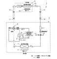
図1は本発明の一実施形態に係る空気調和機に用いる冷凍サイクルの概念図であり、図2は本発明の一実施形態の空気調和機に用いる室外機の機械室内構造を示す斜視図、図3は本発明の一実施形態の空気調和機に用いるシリンダ数切換弁を備えたコンプレッサの縦断面図である。 FIG. 1 is a conceptual diagram of a refrigeration cycle used in an air conditioner according to an embodiment of the present invention, and FIG. 2 is a perspective view showing a machine room structure of an outdoor unit used in the air conditioner of an embodiment of the present invention. FIG. 3 is a longitudinal sectional view of a compressor provided with a cylinder number switching valve used in the air conditioner of one embodiment of the present invention.
図1および図2に示すように、本発明に係る冷凍サイクル装置の一実施例である空気調和機1は、室外機2と室内機3に分離される。 As shown in FIGS. 1 and 2, an air conditioner 1 which is an embodiment of a refrigeration cycle apparatus according to the present invention is separated into an outdoor unit 2 and an indoor unit 3.
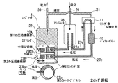
この室外機2は、筐体内を熱交換器室(図示しない)と機械室5とに仕切板(図示しない)で左右に分割し、熱交換器室に収容される室外ファン6および室外熱交換器7と、機械室5内に収容されるコンプレッサ8、冷暖切換え用のサイクル切換弁(四方弁)9、バッファーマフラー10、シリンダ数切換弁11、パルスモータ駆動バルブ(PMV)である電動膨張弁12を備え、室内機3には室内ファン14を備えた室内熱交換器13を備え、室外機2と室内機3は連通管15、16、室外機2に設けられたパックドバルブ17、18を介して順次連通して冷凍サイクルが構成される。
The outdoor unit 2 is divided into a heat exchanger room (not shown) and a machine room 5 by a partition plate (not shown) on the left and right sides, and the outdoor fan 6 and the outdoor heat exchange accommodated in the heat exchanger room. 7, compressor 8 accommodated in machine room 5, cycle switching valve (four-way valve) 9 for cooling / heating switching,
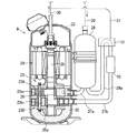
図3に示すように、コンプレッサ8は密閉容器22を備え、この密閉容器22内の下部には圧縮機構部23が、上部には電動機部24がそれぞれ設けられ、これら圧縮機構部23と電動機部24は、回転軸25を介して連結される。
As shown in FIG. 3, the compressor 8 includes a sealed
圧縮機構部23は、2個のシリンダを備えるツインタイプ形で、第1の圧縮機構部を構成する第1のシリンダ23Aと第2の圧縮機構部を構成する第2のシリンダ23Bとから構成される。
The
第1のシリンダ23Aは上部側に設けられ、第1のローリングピストン23a1が偏心回転自在に収容され、第2のシリンダ23Bは第1のシリンダ23Aの下部に中間仕切板26で離間されて設けられ、第2のローリングピストン23b1が偏心回転自在に収容される。
The
サイクル切換弁9(図1)およびシリンダ数切換弁11は、弁の切換え動作時のみ通電して、コイル(ソレノイド)を付勢し、この付勢されたコイルにより弁体を作動させて所定位置に移動させ、所定位置に弁体を機械的手段あるいは磁石などにより保持する自己保持形で、電圧の極性を変換することで弁の切換えを行うことが可能であり、コイルには、例えば12V以下のような直流弱電圧用のものを使用する。従って、サイクル切換弁9およびシリンダ数切換弁11は、弁体を所定位置に保持するために、コイルを常時付勢しておく必要がない。
The cycle switching valve 9 (FIG. 1) and the cylinder
また、サイクル切換弁11は上面に第1の接続口、下面に第2および第3の接続口を備えた3方弁として機能する弁で構成し、第1の接続口と第3の接続口が連通、または第2の接続口と第3の接続口が連通するよう切換えられる構成とする。なお、この弁は、このために設計された3方弁を使用しても良いが、水平方向に弁が作動する構成でなり、通常冷凍サイクルの流路切換え用として使用され量産されている四方切換弁を1箇所の接続口を閉塞して使用しても良い。
The
第1のシリンダ23Aは、吸込側に第1の吸込側配管27aが接続し、一方、第2のシリンダ23Bは、吸込側に第2の吸込側配管27bが接続し、この第2の吸込側配管27bには冷媒のマフラー効果を得るバッファーマフラー10が介設している。
The
冷凍サイクルのコンプレッサ8の吸込側に冷媒を戻すための低圧側配管29には、蒸発器でガス化しきれなかった冷媒が液状のままコンプレッサ8に吸入されるのを防ぐ役割を持つ筒状構造をしたアキュムレータ28が介在されている。
The low-
このアキュムレータ28は、上部に冷媒流入用の低圧側配管29が上方から挿入され、下部に冷媒流出用の2本の配管が下方に延出し、その一方は前記第1の吸込側配管27aとしてコンプレッサの第1のシリンダ23Aに常時連通するよう配管される。また、もう一方は、低圧側連通管29aによりシリンダ数切換弁11の第2の接続口に接続している。
In this
さらにコンプレッサ8の吐出管30と連通する高圧側配管31がシリンダ数切換弁11の第1の接続口に接続し、バッファーマフラー10が介設している第2の吸込側配管27bがシリンダ数切換弁11の第3の接続口に接続される。
Further, a high-
また、密閉容器22の内底部には潤滑油を集溜する油溜り部32が設けられ、第2のシリンダ23Bの全部と、第1のシリンダ23Aのほとんど大部分が油溜り部32の潤滑油中に浸漬される。
An
回転軸25の最下端面は第2の軸受25aから露出していて、ここに図示しない給油ポンプが設けられる。この給油ポンプには給油通路が連通していて、回転軸25の回転にともなって給油ポンプが油溜り部32の潤滑油を吸い上げ、給油通路に導くようになっている。
The lowermost end surface of the rotating
従って、図4に示すように、コンプレッサ8の2個のシリンダを用いた通常の運転では、シリンダ数切換弁11が、第2の接続口と第3の接続口が連通する状態に保持される。アキュムレータ28に流入した冷媒は、ガス冷媒がアキュムレータ28で2分され、一方のガス冷媒は、直接第1のシリンダ23Aに吸い込まれ、他方のガス冷媒はシリンダ数切換弁11を介して第2のシリンダ23Bに吸込まれ、第1のシリンダと第2のシリンダ双方で圧縮作用が行われ、密閉容器22を介して、高圧ガスが吐出管30より吐出される。
Therefore, as shown in FIG. 4, in a normal operation using the two cylinders of the compressor 8, the cylinder
これに対して、図5に示すように、コンプレッサ8の1個のシリンダを用いた小能力運転では、サイクル切換弁11が、第1の接続口と第3の接続口が連通する状態に保持される。第2のシリンダ23Bは、高圧側配管31、サイクル切換弁11およびバッファーマフラー10、第2の吸込側配管27bを介して吐出管30に連通するので、第2シリンダ23Bの吸込側は高圧になり、第2のシリンダ23Bの圧縮室内の圧力差により第2のローリングピストン23b1へと押し付けられ、追従していたベーン23b2は離れ、フリーとなる。この状態で、ベーン背面側に埋め込んだ小磁石23b3によりベーンを吸着、保持する。シリンダではベーンによる仕切りがないため、空運転状態となり、第2のシリンダ23Bでの圧縮作用は停止状態となる。このためアキュムレータ28に戻ったガス冷媒は、一方の、第1の吸込側配管27aを介して第1のシリンダ23Aのみに吸い込まれる。この結果、1個のシリンダのみの運転になる。
On the other hand, as shown in FIG. 5, in the small capacity operation using one cylinder of the compressor 8, the
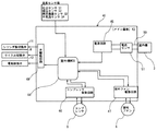
図6に示すように、室外機2は、室外機制御回路41を備える。 As shown in FIG. 6, the outdoor unit 2 includes an outdoor unit control circuit 41.
室外機制御回路41は、メイン基板43に室外機MCU(マイクロコントローラ・ユニット)44をはじめ各種の回路が取り付けられ、室外機MCU44は整流器などを備えた電源回路45を介して電源に接続される。
In the outdoor unit control circuit 41, various circuits including an outdoor unit MCU (microcontroller unit) 44 are attached to the main board 43, and the
室外機MCU44は本発明における室外機側の制御装置をなし、CPU、メモリなどを備え、CPUがROM及びRAMとデータのやりとりを行いながらROMに記憶されている制御プログラムを実行することによって、コンプレッサ8、シリンダ数切換弁11、サイクル切換弁9、電動膨張弁10を含む室外機2の被制御部品を制御する。
The
また、室外機MCU44にはコンプレッサ8を回転制御するコンプレッサ駆動回路46が接続され、さらに、室外ファン6の回転を制御する室外ファン駆動回路47が接続される。
The
また、室外機MCU44にはシリンダ数切換弁11、サイクル切換弁9、電動膨張弁10を開閉駆動する弁駆動回路49が接続される。
The
さらに、室外機MCU44にはコンプレッサ8の吐出側に設けられる吐出センサS1、吸込側に設けられる吸込センサS2、室外熱交換器7に設けられる熱交換器センサS3および外気温センサS4が接続され、吐出センサS1はコンプレッサ8から吐出される冷媒温度を、吸込センサS2はコンプレッサ8に吸込まれる冷媒温度を、熱交換器センサS3は室外熱交換器7内の冷媒温度を、外気温センサS4は外気温度を各々検知し、温度情報として室外機MCU44に入力する。
Furthermore, a discharge sensor S1 provided on the discharge side of the compressor 8, a suction sensor S2 provided on the suction side, a heat exchanger sensor S3 provided on the outdoor heat exchanger 7 and an outside air temperature sensor S4 are connected to the outdoor unit MCU44. The discharge sensor S1 is the refrigerant temperature discharged from the compressor 8, the suction sensor S2 is the refrigerant temperature sucked into the compressor 8, the heat exchanger sensor S3 is the refrigerant temperature in the outdoor heat exchanger 7, and the outside air temperature sensor S4 is Each of the outdoor temperatures is detected and input to the
電源回路45は配線50を介して室内機3側に接続され、配線50には電流センサ51が設けられる。
The
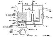
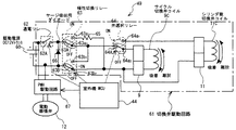
図7に示すように、弁駆動回路49には、DC12Vの駆動電源60としてのトランスと、電動膨張弁12のパルスモータへ駆動パルスを出力するPMV駆動回路67と、サイクル切換弁9とシリンダ切換弁11の切換えを行う切換弁駆動回路61とを備える。この切換弁駆動回路61は、常開スイッチ62Aから構成する通電リレー62と、ON端子63a1およびOFF端子63a2を備えた第1切換スイッチ63AならびにON端子63b1およびOFF端子63b2を備えた第2切換スイッチ63Bから構成する極性切換手段としての極性切換リレー63と、ON端子64a1およびOFF端子64a2を備えた切換スイッチ64Aを構成する弁選択リレー64と、12V以下の直流弱電圧で作動し極性が切り換わることで吸着、離脱の動作を行うサイクル切換弁コイル9Cおよびシリンダ数切換弁コイル11Cとを備えている。
As shown in FIG. 7, the
弁駆動回路49の回路構成は、前記駆動電源60の両端子にPMV駆動回路67が直接接続されると共に、切換弁駆動回路61が前記PMV駆動回路67と並列接続される。即ち、前記駆動電源60のプラス電位側に、通電リレー62の常開スイッチ62Aを介して、極性切換リレー63の第1の切換スイッチ63Aが接続され、前記駆動電源60のマイナス電位側に、極性切換リレー63の第2の切換スイッチ63Bが接続される。極性切換リレー63の第1切換スイッチ63AのON端子63a1は、抵抗65を介して第2切換スイッチ63BのOFF端子63b2に接続され、第2切換スイッチ63BのON端子63b1は、第1切換スイッチ63AのOFF端子63a2に配線接続される。この第1切換スイッチ63AのOFF端子63a2に弁選択リレー64の切換スイッチ64Aが接続され、このOFF端子64a2側にサイクル切換弁コイル9Cの一端側が接続し、またON端子64a1側にシリンダ数切換弁コイル11Cの一端側が接続される。サイクル切換弁コイル9Cおよびシリンダ数切換弁コイル11Cの他端側は、夫々極性切換リレー63の第2の切換スイッチ63BのOFF端子63b2に接続される。さらに、極性切換リレー63の第1切換スイッチ63Aと第2切換スイッチ63B間における配線間にはサージ吸収用のダイオード66が接続される。
The
常開スイッチ62A開閉制御を行う通電リレー62の、第1切換スイッチ63Aと第2切換スイッチ63Bの端子切換えを行う極性切換リレー63、切換スイッチ64Aの端子切換えを行う弁選択リレー64への通電制御は室外機MCU44からの指令によって行われる。
Energization control of the energizing
従って、前記PMV駆動回路67と、前記切換弁駆動回路61の前記サイクル切換弁9の弁位置切換え用のコイル9Cまたは前記シリンダ数切換弁コイル11Cとが、駆動電源60に対し、並列接続されるため、サイクル切換弁9の弁位置切換え用のコイル9Cへの通電、極性切換リレー63による弁切換えおよびシリンダ数切換弁11の弁位置切換え用のコイル11Cへの通電、入力される駆動パルスの数に応じて開度が連続的に変化する電動膨張弁(PMV)のパルス発生は1個の共通の駆動電源60によって行われ、駆動電源が共通化する。
Accordingly, the
図8はリレー、弁の制御相関図で、図中左側は、室外機MCU44のポート、極性切換リレー63、サイクル切換弁コイル9C、およびシリンダ数切換弁コイル11Cの通電の相関を示し、さらに、図中右側では、室外機MCU44のポート、弁選択リレー64と通電されるコイルの相関を示す。
FIG. 8 is a control correlation diagram of relays and valves. The left side of the figure shows the correlation of energization of the port of the
室外機MCU44のポートがLowの場合、極性切換リレー63がOFFとなり、第1切換スイッチ63AがOFF端子63a2に、第2切換スイッチ63BがOFF端子63b2に接続される。
If the port of the outdoor unit MCU44 is Low, polarity switching relay 63 is turned OFF, the first changeover switch 63A is turned OFF terminal 63a 2, the second changeover switch 63B is connected to the
この際弁選択ポートがLowの場合は、弁選択リレー64がOFF端子64a2に接続され冷暖切換えのサイクル切換弁コイル9C側に接続されるため、通電リレー62に1秒間通電を行うとサイクル切換弁コイル9Cが吸着方向に作用し、その状態を保持する。したがって、冷凍サイクルは、冷房モードに維持される。
If this Saiben selected port is Low, since the valve selection relay 64 is connected to the cycle switch valve coil 9C side connected to cooling and heating switched OFF terminal 64a 2, the cycle switching is performed for one second energized energized
また、極性ポートが上記したLowの状態で、弁選択ポートがHighとなった場合は、弁選択リレー64がON端子64a1に接続され、シリンダ数切換弁コイル11C側に接続されるため、通電リレー62に1秒間通電を行うとシリンダ数切換弁コイル11Cが吸着方向に作用し、その状態を保持する。したがって、コンプレッサ8は1シリンダでの運転モードに維持される。
When the polarity port is in the Low state and the valve selection port becomes High, the valve selection relay 64 is connected to the ON terminal 64a 1 and connected to the cylinder number switching valve coil 11C side. When the
また、極性切換ポートをHighに設定した場合は、極性切換リレー63がONとなり、第1切換スイッチ63AがON端子63a1に、第2切換スイッチ63BがON端子63b1に接続される。このため、サイクル切換弁コイル9Cもしくはシリンダ数切換弁コイル11Cへの通電される極性がプラスマイナス逆転する。
Also, if you set the polarity switching port High, the polarity switching relay 63 is turned ON, the first changeover switch 63A is in the
したがって、上述した際弁選択ポートがLowの場合は、通電リレー62に1秒間通電を行うとサイクル切換弁コイル9Cが離脱方向に作用し、その状態を保持する。したがって、冷凍サイクルは、暖房モードに切り換わりその状態が維持される。
Therefore, when the valve selection port is Low at the time described above, when the
また、極性ポートがHighの状態で、弁選択ポートがHighとなった場合は、弁選択リレー64がON端子64a1に接続され、シリンダ数切換弁コイル11C側に接続されるため、通電リレー62に1秒間通電を行うと、シリンダ数切換弁コイル11Cが離脱方向に作用し、その状態を保持する。したがって、コンプレッサ8は2シリンダでの運転モードに維持される。 Further, when the polarity port is High and the valve selection port is High, the valve selection relay 64 is connected to the ON terminal 64a 1 and is connected to the cylinder number switching valve coil 11C side. Is energized for 1 second, the cylinder number switching valve coil 11C acts in the disengagement direction, and the state is maintained. Therefore, the compressor 8 is maintained in the operation mode with two cylinders.
図9は、リレー、弁のシーケンス制御図で、下段から上段へ、PMV駆動回路44から電動膨張弁12のパルスモータへ発せられる駆動パルス、弁選択リレー64への制御信号、極性切換リレー63への制御信号、通電リレーへの制御信号のシーケンスを示す。この図に示されるとおり、通常時は、駆動電源からの電源供給は、全てPMV駆動パルスに供給され、切換弁を切換え操作する場合のみ、PMV駆動パルスを停止し、通電リレー側への電源供給を行う制御を実施している。具体的には、室外機MCUから弁切換え操作信号が出た場合、PMV駆動パルスの発信中にPMV駆動回路にストップパルスを送り、5秒間パルス発信を停止させる。その際、極性切換ポート、および弁選択ポートにLowまたはHighに信号を送り極性切換リレー63、弁選択リレー64を所定モードに設定し、2秒後に1秒間通電リレーをONとし、弁の切換え操作を実行し、その後2秒間その状態を保持した後、PMV駆動回路にスタートパルスを送りPMV駆動パルスの発信を再開する制御を実施する。
FIG. 9 is a sequence control diagram of the relays and valves. From the lower stage to the upper stage, the drive pulse issued from the
次に本実施形態の冷凍サイクル装置の動作について説明する。 Next, operation | movement of the refrigerating-cycle apparatus of this embodiment is demonstrated.
例えば、冷房サイクル運転、暖房サイクル運転が可能な自動運転を実施した場合を説明する。 For example, a case where an automatic operation capable of a cooling cycle operation and a heating cycle operation is performed will be described.
図6および図7に示すように、リモコンなどにより、所望室内温度を設定し、自動運転の運転を操作すると、指定した自動運転の指令が室内機3内に配置した室内制御回路に入力され、室内温度と設定温度差などの条件により冷房運転或いは暖房運転などの運転モードが設定され、この設定されたモードに基づく運転信号が、室内機3側の制御回路から室外機2内に配置した室外機制御回路41に送られ、室外機制御回路41の室外機MCU44からの指令により、設定された運転モードに基づく室外機側の冷凍サイクル回路、圧縮機の運転モードなど運転が実行される。
As shown in FIGS. 6 and 7, when a desired indoor temperature is set by a remote controller or the like and an automatic operation is operated, a designated automatic operation command is input to an indoor control circuit disposed in the indoor unit 3, An operation mode such as a cooling operation or a heating operation is set according to a condition such as a difference between the room temperature and a set temperature, and an operation signal based on the set mode is transmitted from the control circuit on the indoor unit 3 side to the outdoor unit 2. In response to a command from the
例えば、室内温度が設定温度より高い場合は、冷房モードが設定され運転が開始される。 For example, when the room temperature is higher than the set temperature, the cooling mode is set and the operation is started.
図7および図8に示すように、この室内温度情報の入力により、冷房サイクル運転が必要であると指令を受けた室外機MCU44は、室外機MCU44の極性切換ポートがLowにあり、極性切換リレー63を第1、第2切換スイッチ63A、63BがOFF端子63a2、63b2に接続された状態に、弁選択リレー64を切換スイッチ64AがOFF端子64a2に接続された状態にし、通電リレー1を1秒間通電することで、図7および図8に示すように、サイクル切換弁コイル9Cを吸着させる方向に電流が流れ、弁体は、冷凍サイクルが冷房運転可能な状態に保持される。
As shown in FIG. 7 and FIG. 8, the
なお、予め冷房サイクル運転になっており、極性切換リレー63および弁選択64はOFF状態で待機している場合はこの動作は省略される。 Note that this operation is omitted when the cooling cycle operation is performed in advance and the polarity switching relay 63 and the valve selection 64 are waiting in the OFF state.
一方、通常運転では、弁体は離脱状態にあり、図4に示すようなコンプレッサ8の2個のシリンダ23a23Bを用いた通常の冷房運転が可能な状態としている。 On the other hand, in the normal operation, the valve body is in the detached state, and the normal cooling operation using the two cylinders 23a 2 3B of the compressor 8 as shown in FIG. 4 is possible.
図1に実線で冷媒の流れ方向を矢示する冷房運転が開始されると、コンプレッサ8の2個のシリンダ23a23Bを用いた通常の運転では、シリンダ数切換弁11が、第2の接続口と第3の接続口が連通する状態に保持される。アキュムレータ28に戻ったガス冷媒は、アキュムレータ28で2分され、一方の冷媒ガスは、直接第1のシリンダ23Aに吸い込まれ、他方の冷媒ガスはシリンダ数切換弁11を介して第2のシリンダ23Bに吸込まれ、第1のシリンダと第2のシリンダ双方で圧縮作用が行われ、密閉容器22を介して、高圧ガスが吐出管30より吐出される。
When the cooling operation indicated by the solid line in FIG. 1 is started, in the normal operation using the two
吐出管30より吐出された高圧ガスは室外熱交換器7で冷却され、液冷媒となり、液冷媒は電動膨張弁(PMV)12により減圧されると共に所要流量に制御されてから室内熱交換器13内に流入し、ここで蒸発して気化し、外気から吸熱して周囲の空気を冷却し、その冷却空気を室内ファン14により室内へ送風することにより室内を冷房する。
The high-pressure gas discharged from the
一方、室内熱交換器13で蒸発してガス化したガス冷媒は、サイクル切換弁9、シリンダ数切換弁11を介して、第1のシリンダ23Aおよび第2のシリンダ23Bに吸込まれる。
On the other hand, the gas refrigerant evaporated and gasified in the indoor heat exchanger 13 is sucked into the
この冷房運転時、電動膨張弁12の開度が絞られ過ぎて室内熱交換器13内に流入する液状冷媒の流入量が少な過ぎると、その過少の冷媒により外気から大量の熱量を吸熱するので、過熱状態となる場合がある。
During this cooling operation, if the amount of liquid refrigerant flowing into the indoor heat exchanger 13 is too small because the opening of the
そこで、コンプレッサの吸込温度センサS2冷媒の過熱状態を検知し、その情報を室外機MCU44に入力し、この室外機MCU44からの弁制御信号に基づき、弁駆動回路49に設けたPMV駆動回路67が発生する駆動パルスにより、電子膨張弁12に制御パルスを与えて所定開度ずつ開閉し、冷媒流量を制御するようになっている。
Therefore, the compressor intake temperature sensor S2 detects the refrigerant overheating state, inputs the information to the
図9に示すように、室外機MCU44から電動膨張弁12の開度調整指令が出され、図9中「PMV動作中」で示すように、電動膨張弁12のパルスモータに、電動膨張弁駆動回路が発生する駆動パルスが入力され、電動膨張弁12の開度調整が行なわれ、冷媒流量が適正に制御される。
As shown in FIG. 9, an opening degree adjustment command for the
通常の冷房運転が継続され、室内温度が所望の温度に達すると、室内機3に設けた室内温度センサからの温度情報に基づき、室外機MCU44は小能力での省エネルギー運転を行う判断をする。
When the normal cooling operation is continued and the room temperature reaches a desired temperature, the
室外機MCU44が省エネルギー運転を行うと判断するとコンプレッサ8の1シリンダ運転に切換えるための動作を行い、図9に示すシーケンスが実行される。
When the
切換弁駆動回路61による弁切換え動作中は、室外機MCU44からPMV駆動回路67へのパルスの送信は行われず、電動膨張弁12の絞り、開放動作は停止される。
During the valve switching operation by the switching valve drive circuit 61, no pulse is transmitted from the
室外機MCU44は弁選択ポートがHighであり、室外機MCU44は弁駆動回路49に弁選択リレー64を切換えるための駆動信号を送信し、弁選択リレー64の切換スイッチ64AをON端子64a1に接続された状態にする。
The outdoor unit MCU44 is High valve selected port, the outdoor unit MCU44 transmits a drive signal for switching the valve selection relay 64 to the
この弁選択リレー64の動作は通電リレー62を1秒間通電動作させる前後2秒の5秒間設定される。
The valve selection relay 64 is set for 5 seconds, 2 seconds before and after the
この場合も、切換弁駆動回路61による弁切換え動作中は、室外機MCU44からPMV駆動回路67のパルスの送信は行われず、電動膨張弁12の開度制御動作は停止される。
Also in this case, during the valve switching operation by the switching valve drive circuit 61, the pulse transmission of the
弁選択リレー64がON端子64a1に接続されると、シリンダ数切換弁コイル11Cに弁体を吸着する方向の電流が流れ、図5に示すような小能力モード運転が開始される。 When the valve select relay 64 is connected to the ON terminal 64a 1, the direction of current flows to adsorb the valve on the cylinder number switching valve coil 11C, the small capacity mode operation as shown in FIG. 5 is started.
小能力モード運転が開始されると、サイクル切換弁11が、第1の接続口と第3の接続口が連通する状態に保持される。
When the small capacity mode operation is started, the
第2のシリンダ23Bは、高圧側配管31、サイクル切換弁11およびバッファーマフラー10、第2の吸込側配管27bを介して吐出管30に連通するので、第2のシリンダ23Bの吸込側は高圧になり、第2のシリンダ23Bの圧縮室内の圧力差により第2のローリングピストン23b1へと押し付けられ、追従していたベーン23b2は離れ、フリーとなる。
Since the
この状態で、ベーン背面側に埋め込んだ小磁石23b3によりベーンを吸着、保持する。シリンダではベーンによる仕切りがないため、空運転状態となり、第2のシリンダ23Bでの圧縮作用は停止状態となる。
In this state, the vanes are attracted and held by the small magnets 23b3 embedded on the back side of the vanes. Since there is no partition by a vane in a cylinder, it will be in an idling state and the compression action in the
このためアキュムレータ28に戻ったガス冷媒は、一方の、第1の吸込側配管27aを介して第1のシリンダ23Aのみに吸い込まれる。この結果、1個のシリンダのみの運転になり、小能力運転となるため、運転停止を繰り返すことなく運転継続が可能となり省エネルギー運転が行われる。
For this reason, the gas refrigerant that has returned to the
室内温度が上昇して冷房負荷が増加し、室外機MCU44が通常の冷房運転に復帰させると判断すると、通常冷房運転をさせるために、図9に示すシーケンスに基づき、室外機MCU44は弁駆動回路49に極性切換リレー63を切換えるための駆動信号を送信し、極性切換リレー63の第1、第2切換スイッチ63A、63BがON端子63a1、63b1に接続された状態にし、弁選択リレー64を切換スイッチ64AがON端子64a1に接続された状態にし、シリンダ数切換弁コイル11Cに弁体を離脱させる方向の電流を流し、2個のシリンダを用いた通常運転に復帰させる。
If it is determined that the indoor temperature rises and the cooling load increases and the
また、外気温が低下して暖房運転を行う場合、あるいは冷房運転が終了して、室内機に付着した結露を除去するための乾燥運転を行う場合には、暖房サイクル運転による暖房運転が行われる。 In addition, when the outside air temperature is lowered and the heating operation is performed, or when the cooling operation is finished and the drying operation for removing the condensation attached to the indoor unit is performed, the heating operation by the heating cycle operation is performed. .
室外機MCU44が暖房運転を行う指令を受けると、図9に示すシーケンスに基づき、室外機MCU44は弁駆動回路49に極性切換リレー63を切換えるための駆動信号を送信し、極性切換リレー63の第1、第2切換スイッチ63A、63BがON端子63a1、63b1に接続された状態にし、弁選択リレー64を切換スイッチ64AがOFF端子64a2に接続された状態にし、電流の流れを逆にし、サイクル切換弁9のコイル9Cに弁体を離脱させる方向の電流を流し、サイクル切換弁9で冷媒の流れを図1に点線で矢視する方向にする。
When the
この場合も、切換弁駆動回路61による弁切換え動作中は、室外機MCU44からPMV駆動回路67のパルスの送信は行われず、電動膨張弁12の開度制御動作は停止される。
Also in this case, during the valve switching operation by the switching valve drive circuit 61, the pulse transmission of the
この暖房運転においても、サイクル切換弁9の切換えにより、2シリンダによる通常運転、1シリンダによる小能力運転は行われるが、弁駆動回路49の動作は、上記に説明したサイクル切換弁9の切換え以外、冷房運転と異ならないので、説明は省略する。
Also in this heating operation, normal operation by two cylinders and small capacity operation by one cylinder are performed by switching the
本実施形態の空気調和機は、サイクル切換弁9およびシリンダ数切換弁11のコイルには直流弱電圧用のものを使用するので、従来の空気調和機が供給電源仕様(例えば、単相100Vと200V機種)間でそれぞれ異なるコイルを利用していたのと異なり、供給電源に係りなく、同一品を使用することが可能となり、高範囲に渡る空気調和機、冷凍機での標準化を図ることができる。
Since the air conditioner of this embodiment uses a DC weak voltage coil for the
また、サイクル切換弁9およびシリンダ数切換弁11は、切換え時のみに、コイルに通電する方式を採用しているため、運転中に弁位置保持のための消費電力を必要とせず省エネルギー効果に優れ、また、シリンダ数切換弁およびサイクル切換弁の両方に直流弱電圧用のコイルを使用した自己保持形弁を使用するので、一層、省エネルギー効果に優れる。
Further, since the
さらに、機種間で駆動電源仕様が同一であるため、制御基盤に別々の駆動源を配置する必要がなく、同一回路上の切換えのみで2個のコイル操作を制御することが可能であり、生産性に優れる。 Furthermore, since the drive power supply specifications are the same between models, there is no need to place separate drive sources on the control board, and it is possible to control the operation of two coils by simply switching on the same circuit. Excellent in properties.
本実施形態の冷凍サイクル装置によれば、電圧の異なる冷凍サイクル装置間で、同一コイルを使用することが可能となり、高範囲に渡る冷凍サイクル装置での標準化を図ることができ、さらに、コイルを切換え時のみの通電方式とし、運転中に弁位置保持のための消費電力を必要とせず省エネルギー化を図ることができる冷凍サイクル装置が実現する。 According to the refrigeration cycle apparatus of the present embodiment, the same coil can be used between refrigeration cycle apparatuses having different voltages, and standardization in a refrigeration cycle apparatus over a high range can be achieved. A refrigeration cycle apparatus is realized that is energized only at the time of switching and does not require power consumption for holding the valve position during operation and can save energy.
1…空気調和機、2…室外機、3…室内機、4…筐体、5…機械室、6…室外ファン、7…室外熱交換器、8…コンプレッサ、9…サイクル切換弁、9C…サイクル切換弁コイル、10…バッファーマフラー、11…シリンダ数切換弁、11C…シリンダ数切換弁コイル、12…電動膨張弁、13…室内熱交換器、14…室内ファン、22…密閉容器、23…圧縮機構部、23A…第1の圧縮機構部を構成する第1のシリンダ、23B…第2の圧縮機構部を構成する第2のシリンダ、24…電動機部、25…回転軸、25a…第2の軸受、26…中間仕切板、27a…第1の吸込側配管、27b…第2の吸込側配管、28…アキュムレータ、29…低圧側配管、29a…低圧側連通管、30…吐出管、31…高圧側配管、41…室外機制御回路、43…メイン基板、44…室外機MCU、45…電源回路、46…コンプレッサ駆動回路、47…室外ファン駆動回路、49…弁駆動回路、60…駆動電源、61…切換弁駆動回路、62…通電リレー、常開スイッチ62A、63…極性切換リレー、63A…第1切換スイッチ、63a1…ON端子、63a2…OFF端子、63B…第2切換スイッチ、63b1…ON端子、63b2…OFF端子、64…弁選択リレー、64A…切換スイッチ、64a1…ON端子、64a2…OFF端子、67…PMV駆動回路。
DESCRIPTION OF SYMBOLS 1 ... Air conditioner, 2 ... Outdoor unit, 3 ... Indoor unit, 4 ... Housing, 5 ... Machine room, 6 ... Outdoor fan, 7 ... Outdoor heat exchanger, 8 ... Compressor, 9 ... Cycle switching valve, 9C ... Cycle switching valve coil, 10 ... Buffer muffler, 11 ... Cylinder number switching valve, 11C ... Cylinder number switching valve coil, 12 ... Electric expansion valve, 13 ... Indoor heat exchanger, 14 ... Indoor fan, 22 ... Sealed container, 23 ... Compression mechanism section, 23A ... first cylinder constituting the first compression mechanism section, 23B ... second cylinder constituting the second compression mechanism section, 24 ... electric motor section, 25 ... rotating shaft, 25a ...
Claims (3)
前記電動膨張弁は、駆動パルスにより弁開度が制御される弁であり、前記サイクル切換弁は、弁の切換え動作時のみコイルに通電して弁を切換える自己保持形弁であり、
前記弁駆動回路は、1個の駆動電源と、この駆動電源に接続し前記電動膨張弁に駆動パルスを発生させる電動膨張弁駆動回路と、同じく前記駆動電源に接続しサイクル切換弁の切換えを行う切換弁駆動回路とを備え、
前記制御装置は、通常運転状態で、前記電動膨張弁駆動回路に前記駆動パルスを発信するよう制御し、サイクル切換弁の切換動作時は、前記電動膨張弁駆動回路の前記駆動パルスの発信を停止させた状態で、切換弁駆動回路に駆動制御信号を送信する制御手段を備えている
ことを特徴とする冷凍サイクル装置。 A compressor, a cycle switching valve that switches a refrigerant flow during cooling operation and heating operation of the refrigeration cycle, an electric expansion valve that depressurizes the refrigerant and controls a flow rate, a valve drive circuit that performs a drive operation of each valve, and the valve In the refrigeration cycle apparatus comprising a control device that transmits a valve control signal to the drive circuit and controls the drive of each valve,
The electric expansion valve is a valve whose valve opening is controlled by a drive pulse, and the cycle switching valve is a self-holding valve that switches a valve by energizing a coil only during a valve switching operation,
The valve drive circuit is connected to one drive power supply, an electric expansion valve drive circuit that is connected to the drive power supply and generates a drive pulse in the electric expansion valve, and is also connected to the drive power supply to switch a cycle switching valve. A switching valve drive circuit,
The control device controls to transmit the drive pulse to the electric expansion valve drive circuit in a normal operation state, and stops the transmission of the drive pulse of the electric expansion valve drive circuit during the switching operation of the cycle switching valve. A refrigeration cycle apparatus comprising: control means for transmitting a drive control signal to the switching valve drive circuit in a state of being made to operate.
前記電動膨張弁は、駆動パルスにより弁開度が制御される弁であり、前記シリンダ数切換弁および前記サイクル切換弁は、夫々弁の切換え動作時のみコイルに通電して弁を切換える自己保持形弁であり、
前記弁駆動回路は、1個の駆動電源と、この駆動電源に接続し前記電動膨張弁に駆動パルスを発生させる電動膨張弁駆動回路と、同じく前記駆動電源に接続しシリンダ数切換弁あるいはサイクル切換弁の切換を行う切換弁駆動回路とを備え、
前記制御装置は、通常運転状態では、前記電動膨張弁駆動回路に前記駆動パルスを発信するよう制御すると共に、シリンダ数切換弁およびサイクル切換弁の切換動作時は、前記電動膨張弁駆動回路の前記駆動パルスの発信を停止させた状態で、切換弁駆動回路に切換え駆動信号を送信することを特徴とする冷凍サイクル装置。 A compressor having two cylinders that can be used by selectively switching one or two, a cylinder number switching valve that is provided on the suction side of the compressor and that switches between operation of one or two cylinders, and a refrigeration cycle A cycle switching valve that switches the flow of refrigerant during cooling and heating operations, an electric expansion valve that depressurizes the refrigerant and controls the flow rate, a valve drive circuit that drives each of the valves, and valve control for the valve drive circuit In the refrigeration cycle apparatus including a control device that transmits a signal and controls the driving of each valve,
The electric expansion valve is a valve whose valve opening degree is controlled by a drive pulse, and the cylinder number switching valve and the cycle switching valve are self-holding types in which the coil is switched by energizing the coil only during the valve switching operation. Valve,
The valve drive circuit includes one drive power supply, an electric expansion valve drive circuit that is connected to the drive power supply and generates a drive pulse in the electric expansion valve, and is connected to the drive power supply and is connected to the cylinder number switching valve or cycle switching. A switching valve drive circuit for switching the valve,
The control device controls to transmit the drive pulse to the electric expansion valve drive circuit in a normal operation state, and at the time of switching operation of the cylinder number switching valve and the cycle switching valve, the electric expansion valve drive circuit A refrigeration cycle apparatus that transmits a switching drive signal to a switching valve drive circuit in a state where transmission of drive pulses is stopped.
Priority Applications (1)
| Application Number | Priority Date | Filing Date | Title |
|---|---|---|---|
| JP2008269694A JP5357495B2 (en) | 2008-10-20 | 2008-10-20 | Refrigeration cycle equipment |
Applications Claiming Priority (1)
| Application Number | Priority Date | Filing Date | Title |
|---|---|---|---|
| JP2008269694A JP5357495B2 (en) | 2008-10-20 | 2008-10-20 | Refrigeration cycle equipment |
Publications (2)
| Publication Number | Publication Date |
|---|---|
| JP2010096472A true JP2010096472A (en) | 2010-04-30 |
| JP5357495B2 JP5357495B2 (en) | 2013-12-04 |
Family
ID=42258285
Family Applications (1)
| Application Number | Title | Priority Date | Filing Date |
|---|---|---|---|
| JP2008269694A Active JP5357495B2 (en) | 2008-10-20 | 2008-10-20 | Refrigeration cycle equipment |
Country Status (1)
| Country | Link |
|---|---|
| JP (1) | JP5357495B2 (en) |
Citations (5)
| Publication number | Priority date | Publication date | Assignee | Title |
|---|---|---|---|---|
| JPH04158142A (en) * | 1990-10-19 | 1992-06-01 | Matsushita Electric Ind Co Ltd | Controller of air conditioner |
| JPH06180140A (en) * | 1992-12-11 | 1994-06-28 | Toshiba Corp | Air-conditioner |
| JPH11211291A (en) * | 1998-01-20 | 1999-08-06 | Saginomiya Seisakusho Inc | Method and apparatus for supplying electric power for driving cooling-heating unit |
| JP2005098654A (en) * | 2003-09-26 | 2005-04-14 | Daikin Ind Ltd | Power source controller and air conditioner using the same |
| JP2005171897A (en) * | 2003-12-11 | 2005-06-30 | Toshiba Kyaria Kk | Refrigerating cycle device |
-
2008
- 2008-10-20 JP JP2008269694A patent/JP5357495B2/en active Active
Patent Citations (5)
| Publication number | Priority date | Publication date | Assignee | Title |
|---|---|---|---|---|
| JPH04158142A (en) * | 1990-10-19 | 1992-06-01 | Matsushita Electric Ind Co Ltd | Controller of air conditioner |
| JPH06180140A (en) * | 1992-12-11 | 1994-06-28 | Toshiba Corp | Air-conditioner |
| JPH11211291A (en) * | 1998-01-20 | 1999-08-06 | Saginomiya Seisakusho Inc | Method and apparatus for supplying electric power for driving cooling-heating unit |
| JP2005098654A (en) * | 2003-09-26 | 2005-04-14 | Daikin Ind Ltd | Power source controller and air conditioner using the same |
| JP2005171897A (en) * | 2003-12-11 | 2005-06-30 | Toshiba Kyaria Kk | Refrigerating cycle device |
Also Published As
| Publication number | Publication date |
|---|---|
| JP5357495B2 (en) | 2013-12-04 |
Similar Documents
| Publication | Publication Date | Title |
|---|---|---|
| WO1998005907A1 (en) | Transfer valve, method of controlling transfer valve, freezing cycle and method of controlling freezing cycle | |
| JP2007303732A (en) | Air conditioner | |
| JP2005121333A (en) | Air conditioner | |
| JPH0861790A (en) | Air conditioner | |
| JP5357495B2 (en) | Refrigeration cycle equipment | |
| JP2000346478A (en) | Refrigerator | |
| JP5223873B2 (en) | Air conditioner | |
| JP2010096479A (en) | Air conditioner | |
| JP2003004332A (en) | Multiple gas heat pump type air conditioner | |
| US3370437A (en) | Defrosting system | |
| JPH04251160A (en) | Freezing cycle device | |
| JP2010048500A (en) | Refrigerating cycle device | |
| US6276154B1 (en) | Two step metering device | |
| JP4773637B2 (en) | Multi-type gas heat pump type air conditioner | |
| JP2002168534A (en) | Heat pump system of air conditioner | |
| JPH05322331A (en) | Air conditioner | |
| JP2001248882A (en) | Controller for refrigeration cycle | |
| JP6024203B2 (en) | Air conditioner for vehicles | |
| JP4658395B2 (en) | Multi-type gas heat pump type air conditioner | |
| RU2230265C2 (en) | Operation method for vapor-compression cooling machine and cooling machine for method implementation | |
| JP2017031819A (en) | Reciprocating compressor, refrigerator, and humidity conditioner | |
| JPS6340758Y2 (en) | ||
| JP2002295715A (en) | Fluid control valve | |
| JP2007154854A (en) | Pwm driving system for inductive load | |
| JPS6015849B2 (en) | air conditioner |
Legal Events
| Date | Code | Title | Description |
|---|---|---|---|
| A621 | Written request for application examination |
Free format text: JAPANESE INTERMEDIATE CODE: A621 Effective date: 20110921 |
|
| A131 | Notification of reasons for refusal |
Free format text: JAPANESE INTERMEDIATE CODE: A131 Effective date: 20130108 |
|
| A521 | Request for written amendment filed |
Free format text: JAPANESE INTERMEDIATE CODE: A523 Effective date: 20130225 |
|
| TRDD | Decision of grant or rejection written | ||
| A01 | Written decision to grant a patent or to grant a registration (utility model) |
Free format text: JAPANESE INTERMEDIATE CODE: A01 Effective date: 20130813 |
|
| A61 | First payment of annual fees (during grant procedure) |
Free format text: JAPANESE INTERMEDIATE CODE: A61 Effective date: 20130830 |
|
| R150 | Certificate of patent or registration of utility model |
Ref document number: 5357495 Country of ref document: JP Free format text: JAPANESE INTERMEDIATE CODE: R150 Free format text: JAPANESE INTERMEDIATE CODE: R150 |
|
| R250 | Receipt of annual fees |
Free format text: JAPANESE INTERMEDIATE CODE: R250 |
|
| R250 | Receipt of annual fees |
Free format text: JAPANESE INTERMEDIATE CODE: R250 |
|
| R250 | Receipt of annual fees |
Free format text: JAPANESE INTERMEDIATE CODE: R250 |
|
| R250 | Receipt of annual fees |
Free format text: JAPANESE INTERMEDIATE CODE: R250 |
|
| R250 | Receipt of annual fees |
Free format text: JAPANESE INTERMEDIATE CODE: R250 |
|
| R250 | Receipt of annual fees |
Free format text: JAPANESE INTERMEDIATE CODE: R250 |