JP2010094568A - Device for washing deposited sand - Google Patents
Device for washing deposited sand Download PDFInfo
- Publication number
- JP2010094568A JP2010094568A JP2008264778A JP2008264778A JP2010094568A JP 2010094568 A JP2010094568 A JP 2010094568A JP 2008264778 A JP2008264778 A JP 2008264778A JP 2008264778 A JP2008264778 A JP 2008264778A JP 2010094568 A JP2010094568 A JP 2010094568A
- Authority
- JP
- Japan
- Prior art keywords
- sand
- washing
- settling
- earth
- sediment
- Prior art date
- Legal status (The legal status is an assumption and is not a legal conclusion. Google has not performed a legal analysis and makes no representation as to the accuracy of the status listed.)
- Granted
Links
- 239000004576 sand Substances 0.000 title claims abstract description 253
- 238000005406 washing Methods 0.000 title claims abstract description 87
- XLYOFNOQVPJJNP-UHFFFAOYSA-N water Substances O XLYOFNOQVPJJNP-UHFFFAOYSA-N 0.000 claims abstract description 93
- 230000005484 gravity Effects 0.000 claims abstract description 15
- 239000000126 substance Substances 0.000 claims abstract description 13
- 239000002689 soil Substances 0.000 claims abstract description 11
- 239000005416 organic matter Substances 0.000 claims description 75
- 239000010865 sewage Substances 0.000 claims description 75
- 239000013049 sediment Substances 0.000 claims description 46
- 239000007788 liquid Substances 0.000 claims description 40
- 238000004140 cleaning Methods 0.000 claims description 37
- 239000010802 sludge Substances 0.000 claims description 20
- 238000000926 separation method Methods 0.000 claims description 19
- 238000007667 floating Methods 0.000 claims description 7
- 238000004519 manufacturing process Methods 0.000 claims description 7
- 230000032258 transport Effects 0.000 claims 1
- 238000004062 sedimentation Methods 0.000 abstract description 32
- 238000011084 recovery Methods 0.000 abstract description 18
- 239000000203 mixture Substances 0.000 abstract description 5
- 239000011859 microparticle Substances 0.000 abstract 1
- 230000000694 effects Effects 0.000 description 17
- 238000010790 dilution Methods 0.000 description 9
- 239000012895 dilution Substances 0.000 description 9
- 239000002245 particle Substances 0.000 description 8
- 239000000835 fiber Substances 0.000 description 7
- 238000002347 injection Methods 0.000 description 7
- 239000007924 injection Substances 0.000 description 7
- 238000009825 accumulation Methods 0.000 description 6
- 230000001965 increasing effect Effects 0.000 description 6
- 238000000034 method Methods 0.000 description 5
- -1 silt Substances 0.000 description 5
- 238000003756 stirring Methods 0.000 description 5
- 241000208125 Nicotiana Species 0.000 description 4
- 235000002637 Nicotiana tabacum Nutrition 0.000 description 4
- 239000004927 clay Substances 0.000 description 4
- 230000002093 peripheral effect Effects 0.000 description 4
- 230000000630 rising effect Effects 0.000 description 4
- 235000013311 vegetables Nutrition 0.000 description 4
- 239000002351 wastewater Substances 0.000 description 4
- 206010011224 Cough Diseases 0.000 description 3
- 238000007664 blowing Methods 0.000 description 3
- 238000005273 aeration Methods 0.000 description 2
- 230000007423 decrease Effects 0.000 description 2
- 239000000463 material Substances 0.000 description 2
- VNWKTOKETHGBQD-UHFFFAOYSA-N methane Chemical compound C VNWKTOKETHGBQD-UHFFFAOYSA-N 0.000 description 2
- 238000005086 pumping Methods 0.000 description 2
- 238000010008 shearing Methods 0.000 description 2
- 239000007787 solid Substances 0.000 description 2
- 238000003860 storage Methods 0.000 description 2
- 230000005540 biological transmission Effects 0.000 description 1
- 238000010276 construction Methods 0.000 description 1
- 230000018044 dehydration Effects 0.000 description 1
- 238000006297 dehydration reaction Methods 0.000 description 1
- 238000010586 diagram Methods 0.000 description 1
- 238000007599 discharging Methods 0.000 description 1
- 238000004090 dissolution Methods 0.000 description 1
- 239000010840 domestic wastewater Substances 0.000 description 1
- 230000002708 enhancing effect Effects 0.000 description 1
- 239000010419 fine particle Substances 0.000 description 1
- 239000012530 fluid Substances 0.000 description 1
- 239000010800 human waste Substances 0.000 description 1
- 229910052500 inorganic mineral Inorganic materials 0.000 description 1
- 239000002184 metal Substances 0.000 description 1
- 239000011707 mineral Substances 0.000 description 1
- 235000019645 odor Nutrition 0.000 description 1
- 239000011368 organic material Substances 0.000 description 1
- 239000013618 particulate matter Substances 0.000 description 1
- 238000004094 preconcentration Methods 0.000 description 1
- 238000002203 pretreatment Methods 0.000 description 1
- 230000001737 promoting effect Effects 0.000 description 1
- 230000005855 radiation Effects 0.000 description 1
- 238000005507 spraying Methods 0.000 description 1
- 238000010792 warming Methods 0.000 description 1
- 239000002699 waste material Substances 0.000 description 1
- 239000002023 wood Substances 0.000 description 1
Images

Landscapes
- Separation Of Solids By Using Liquids Or Pneumatic Power (AREA)
Abstract
Description
本発明は、沈砂洗浄装置、詳しくは沈砂池から排出された沈砂を洗浄する沈砂洗浄装置に関する。 The present invention relates to a sand settling apparatus, and more particularly, to a sand settling apparatus that cleans sand settling from a sand settling basin.
下水や雨水が導入される下水処理場では、沈砂池において下水中のし渣・砂などを沈降分離し、池底に沈降した沈砂を洗砂槽へポンプ圧送し、ここで沈砂洗浄装置により沈砂の洗浄を行っている。一般に、下水中には0.0001〜0.005容積%の沈砂が含まれている。
従来の沈砂洗浄装置は、洗砂槽と洗砂槽内下部に曝気ノズルと洗浄水ノズルとが設けられ、洗砂槽底部には沈降した洗砂を槽外に排出する移送手段が設けられた構成である。まず、洗砂槽において、沈砂を強曝気しながら洗浄水を流入させ、沈砂に付着した悪臭の基となる有機物(腐敗有機物)を洗い流す。比重が小さい有機物は沈降せず、洗砂槽の越流水(分離水)と一緒に沈砂池へ戻される。一方、洗砂槽の底部に沈降した土砂(洗砂)は、回収コンベアやバスケットにより回収され、埋め立て処分地などへ輸送される。洗砂槽での土砂の回収率は、40%程度と低い。
また、下水が下水処理場へ導入されるまでに、下水管渠やポンプ場の管路施設には、し渣などの有機物や土砂が堆積する。これらの堆積物は、通水を阻害し、悪臭を発生するため、定期的に浚渫土砂として排除され、前述の沈砂と同様に、浚渫土砂は洗砂槽で洗浄する。この場合も、洗砂槽での土砂の回収率は低い。
In a sewage treatment plant where sewage and rainwater are introduced, sediment and sand, etc. in the sewage are settled and separated in a sand basin, and the sand that has settled on the bottom of the pond is pumped to a sand-washing tank, where We are cleaning. Generally, sewage contains 0.0001 to 0.005 volume% of sand.
In the conventional sand washing apparatus, an aeration nozzle and a washing water nozzle are provided at the bottom of the sand washing tank and the sand washing tank, and a transfer means for discharging the washed sand is provided at the bottom of the sand washing tank. It is a configuration. First, in the sand washing tank, washing water is allowed to flow while the sand is strongly aerated to wash away organic matter (rotted organic matter) that is a base of malodor adhering to the sand. Organic matter with a low specific gravity does not settle and is returned to the sand basin along with the overflow water (separated water) of the sand wash tank. On the other hand, the earth and sand (washed sand) settled at the bottom of the sand washing tank is collected by a collection conveyor and a basket and transported to a landfill disposal site. The collection rate of earth and sand in the sand washing tank is as low as about 40%.
In addition, organic matter such as sediment and earth and sand accumulate in the pipe facilities of the sewage pipes and pump stations before the sewage is introduced into the sewage treatment plant. Since these deposits impede water flow and generate bad odors, they are regularly removed as dredged sand, and the dredged sand is washed in a sand washing tank in the same manner as the above-mentioned sedimentation. Also in this case, the collection rate of earth and sand in the sand washing tank is low.
ところで、都市部の下水処理場では、汚泥の集中処理を行っているため、最初沈殿池や最終沈殿池の汚泥を送泥する前に、送泥管内に比重が大きい沈砂が溜まらないように、予め液体サイクロンなどを使用し、汚泥から沈砂を分離する前処理を行っている。あるいは、一般的な下水処理場においても、汚泥濃縮機の磨耗・閉塞を防ぐため、同様に汚泥から砂を分離する前処理を行う場合がある。ここで分離された沈砂も、紙繊維分などの有機物を多く含むなどの理由から、洗砂槽で洗浄することが多い。ただし、前述と同様に、洗砂槽における土砂の回収率は低く、分離された砂の粒度にもよるが、20〜10%以下と非常に少ない。そのため、現状においては、汚泥中の粒子の小さな砂は、系外へ取り出すことは困難であり、下水処理場内を循環している状況となっている。 By the way, in the sewage treatment plant in the city, since sludge is concentrated, before the sludge in the first sedimentation basin and final sedimentation basin is sent, sediment with large specific gravity does not accumulate in the mud pipe. Pretreatment is carried out to separate the sediment from sludge using a liquid cyclone in advance. Or in a general sewage treatment plant, in order to prevent wear and blockage of the sludge concentrator, a pretreatment for separating sand from sludge may be performed in the same manner. The sand settling separated here is often washed in a sand washing tank because it contains a lot of organic matter such as paper fiber. However, similarly to the above, the recovery rate of earth and sand in the sand washing tank is low, and depending on the particle size of the separated sand, it is very low as 20 to 10% or less. Therefore, in the present situation, sand with small particles in the sludge is difficult to take out of the system and is circulating in the sewage treatment plant.
一方、近年の埋立地では、埋立地の残余年数の確保や温暖化ガスとなるメタンガスの発生抑制などの目的で、埋め立て物である有機物を低減する傾向にある。そのため、引き受け可能な砂の有機物含有率(熱しゃく減量)を10〜15%以下と規定している場合も多く、有機物量が多ければ埋立地で引き受けてもらえない。例えば、都市によっては、引き受け可能な砂の有機物含有率(熱しゃく減量)を15%以下と規定しているところがある。そのため、下水処理場において沈砂を十分に洗浄する必要がある。
しかしながら、悪臭の基となる有機物(腐敗有機物)を除去することを目的とした従来の沈砂洗浄装置では、ここまでの有機物含有率の低減は容易ではなく、確実に有機物を洗い流そうとすれば土砂も殆ど流れ出てしまい、土砂の回収率と有機物の除去とを両立させることは困難である。このため、この両立が可能な新しい洗砂装置の開発が要望されていた。
On the other hand, in recent landfills, there is a tendency to reduce organic matter as landfills for the purpose of securing the remaining years of landfills and suppressing the generation of methane gas, which is a warming gas. Therefore, in many cases, the organic matter content (heat loss) of sand that can be accepted is defined as 10 to 15% or less, and if the amount of organic matter is large, it cannot be accepted at a landfill. For example, some cities stipulate that the acceptable organic content (heat loss) of sand is 15% or less. For this reason, it is necessary to thoroughly wash the sedimentation in the sewage treatment plant.
However, with the conventional sand settling device that aims to remove the organic matter (septic organic matter) that is the basis of malodor, it is not easy to reduce the organic content so far. The earth and sand also almost flow out, and it is difficult to achieve both the earth and sand recovery rate and the organic matter removal. For this reason, development of the new sand-washing apparatus which can perform this compatibility was requested | required.
本発明者らは、従来の沈砂洗浄装置に代えて、洗浄槽内に微細気泡を含む混気水を噴出することで、せん断力により沈砂に含まれる微小粒子の細砂・シルト・粘土を有機物から分離させるとともに、この微細気泡が有機物に付着することで粗大な有機物も浮上し流出しやすくできることが判明した。また、この洗浄槽内に傾斜分離板を有する傾斜板式洗砂分離機を採用することで、微細気泡により洗浄槽全体が攪拌され、液面まで土砂が舞い上がることを防ぐとともに、その傾斜板間の平行な隙間へ汚水を流入させることで、有機物と土砂とを比重差を利用して効率よく重力分離し、多くの土砂を捕捉・回収できることが判明した。これにより、上述した問題が解消されることを知見し、この発明を完成させた。
かくして、本発明は、汚水に含まれる土砂の高回収率と、沈砂に含まれる有機物の高除去率とが同時に得られる沈砂洗浄装置を提供することを目的としている。
The present inventors instead of using a conventional sand settling apparatus, spraying mixed water containing fine bubbles into a washing tank, thereby removing fine particles of fine sand, silt, and clay contained in the settling sand by an organic material. It was found that the coarse bubbles can float and flow out easily when these fine bubbles adhere to the organic matter. In addition, by adopting an inclined plate type sandwashing separator having an inclined separating plate in this washing tank, the entire washing tank is agitated by fine bubbles to prevent the earth and sand from rising to the liquid level, and between the inclined plates. It was found that by flowing sewage into parallel gaps, organic matter and earth and sand can be efficiently separated by gravity using the difference in specific gravity, and many earth and sand can be captured and recovered. As a result, the inventors have found that the above-described problems can be solved, and have completed the present invention.
Thus, an object of the present invention is to provide a sand-washing apparatus capable of simultaneously obtaining a high recovery rate of earth and sand contained in sewage and a high removal rate of organic substances contained in the sand.
請求項1に記載の発明は、沈砂池の底部から沈砂移送機により移送された有機物や土砂を含む汚水を導入する洗浄槽を有し、該洗浄槽に収納され、傾斜板間の平行な隙間に流入した前記汚水中から、前記有機物と前記土砂とを比重差を利用して重力分離する傾斜板式洗砂分離機と、前記洗浄槽内に微細気泡を含む混気水をノズルから噴出して前記土砂を洗浄する混気水製造機と、前記洗浄槽の下部から洗浄された土砂を回収する土砂回収コンベアとを備え、前記洗浄槽の液面付近に浮上した有機物を含む分離液を前記沈砂池へ戻す管路を設けたこと特徴とした沈砂洗浄装置である。 The invention described in claim 1 has a washing tank for introducing sewage containing organic matter and earth and sand transferred from the bottom of the sand basin by a sand settling machine, and is housed in the washing tank and includes a parallel gap between the inclined plates. An inclined plate type sandwashing separator that gravity separates the organic matter and the earth and sand from the wastewater that has flowed into the wastewater, and a mixed water containing fine bubbles in the washing tank is ejected from the nozzle. An air-mixed water producing machine for washing the earth and sand, and a earth and sand collection conveyor for collecting the earth and sand washed from the lower part of the washing tank, wherein the separation liquid containing the organic matter floating near the liquid surface of the washing tank It is a sand washing device characterized by providing a pipeline to return to the pond.
請求項1に記載の発明によれば、洗浄槽内に微細気泡を含む混気水をノズルから噴出することで、土砂に含まれる有機物を洗い流す。また、傾斜板群により、分離砂の沈降距離を短縮し、分離した土砂を傾斜板に沿って落下させ、微細気泡が付着した有機物は傾斜板下面に沿って上昇することにより、上向流する洗浄後汚水に土砂が混合することがなく、土砂の沈降速度を速めることができる。前記混気水が微細気泡を含むので、気泡の浮力によるせん断力により土砂中の細砂・シルト・粘土と有機物を解すことができ、かつ有機物に微細気泡を付着させることで有機物の浮上性を高め、傾斜板式沈降分離装置での有機物と土砂との分離性を高めることができる。しかも、微細気泡を混気水として洗浄槽内、特にその底部にノズルから好ましくは槽の下方に向けて吹き込むことで、土砂と共に沈降した紙繊維や髪の毛などの繊維状有機物あるいは粗大な野菜屑やタバコのフィルターなどのし渣を再度洗い解し、流し出すことができる。
また、傾斜板式洗砂分離機を採用したので、汚水が傾斜板間の平行な隙間に流入した際、有機物と土砂との分離時間を早め、比重差を利用して効率よく重力分離することができる。これにより、汚水に含まれる土砂の高回収率と、土砂に含まれる有機物の高除去率とを同時に得ることができる。
According to invention of Claim 1, the organic substance contained in earth and sand is washed away by ejecting the mixed water containing a fine bubble in a washing tank from a nozzle. In addition, the inclined plate group shortens the settling distance of the separated sand, drops the separated earth and sand along the inclined plate, and the organic matter attached with fine bubbles rises along the lower surface of the inclined plate, thereby flowing upward. Sediment does not mix with sewage after washing, and sedimentation speed of sediment can be increased. Since the mixed water contains fine bubbles, it is possible to dissolve fine sand, silt, clay and organic matter in the earth and sand by shearing force due to the buoyancy of the bubbles, and by attaching fine bubbles to the organic matter, the floatability of the organic matter can be improved. It is possible to enhance the separability between the organic matter and the earth and sand in the inclined plate type sedimentation separator. In addition, by blowing fine bubbles into the washing tank as mixed water, particularly from the nozzle toward the bottom of the tank, preferably toward the bottom of the tank, fibrous organic matter such as paper fibers and hair that have settled together with earth and sand, or coarse vegetable waste or The residue such as tobacco filters can be washed again and washed out.
In addition, an inclined plate type sandwashing separator is adopted, so when sewage flows into the parallel gap between the inclined plates, the separation time between organic matter and earth and sand can be shortened, and gravity separation can be performed efficiently using the specific gravity difference. it can. Thereby, the high recovery rate of the earth and sand contained in sewage and the high removal rate of the organic substance contained in earth and sand can be obtained simultaneously.
洗浄槽の形状としては、例えば平面視して矩形状や円形状、底部が下方に向って徐々に断面積が小さくなったホッパ形状などを採用することができる。ホッパ型の洗浄槽の場合、底部の傾斜角は水平に対して45°以上、好ましくは60°以上90°未満である。45°未満では、洗浄した砂の堆積が生じる可能性が高い。ただし、機械的な集砂装置を具備する場合には、集砂装置で掻き集められるため、傾斜角は水平に対して10°以上、好ましくは20°以上90°未満で良い。
汚水とは、例えば下水に流れ込む生活排水や雨水から沈砂池で回収した沈砂や管路施設に堆積した浚渫汚泥、沈殿池汚泥やし尿・浄化槽汚泥から液体サイクロンなどで分離された分離砂、建設現場や河川・湾岸・湖沼などの浚渫土砂などを含む廃水である。
沈砂とは、下水処理場の沈砂池で沈降・捕捉された土砂等であり、礫・砂・シルト・粘土などの無機物とともに、紙繊維や木片・野菜屑・タバコのフィルターなどのし渣や固形状の各種の有機物を含むものをいう。主な無機物は、砂や礫であり、粒径は200μm〜10mm程度が主であるが、200μm以下の細砂やシルトも含まれる。
As the shape of the cleaning tank, for example, a rectangular shape or a circular shape in a plan view, a hopper shape in which a cross-sectional area is gradually reduced toward the bottom, and the like can be adopted. In the case of a hopper type washing tank, the inclination angle of the bottom is 45 ° or more, preferably 60 ° or more and less than 90 ° with respect to the horizontal. Below 45 °, there is a high probability of cleaning sand accumulation. However, when a mechanical sand collecting device is provided, the slant angle is 10 ° or more, preferably 20 ° or more and less than 90 ° with respect to the horizontal, because it is scraped by the sand collecting device.
Sewage refers to, for example, domestic wastewater that flows into sewage, sand collected from rainwater in a sand basin, dredged sludge accumulated in pipeline facilities, separated sand separated from sediment pond sludge, human waste, septic tank sludge, etc., construction site And wastewater including dredged material such as rivers, bays and lakes.
Sedimentation is earth and sand settled and captured in a sand basin at a sewage treatment plant. In addition to minerals such as gravel, sand, silt, and clay, paper sediments such as paper fibers, wood chips, vegetable scraps, tobacco filters, etc. The thing containing various kinds of organic matter. The main inorganic substances are sand and gravel, and the particle size is mainly about 200 μm to 10 mm, but fine sand and silt of 200 μm or less are also included.
沈砂移送機としては、例えば、バケットコンベアにより回収した沈砂を圧送する送砂ポンプ方式の沈砂移送機を採用することができる。その他、加圧水と空気とを利用して沈砂を真空吸引移送する混気ジェットポンプ方式の沈砂移送機などでもよい。 As the sand settling machine, for example, a sand feeding pump type sand set feeding machine that pumps the set sand collected by a bucket conveyor can be adopted. In addition, a mixed air jet pump type sand settling machine or the like that sucks and transfers sand settling using pressurized water and air may be used.
傾斜板式洗砂分離機としては、例えば、洗浄槽内に複数枚の傾斜板を互いに平行な離間状態で並設した傾斜板が収納された傾斜板群を採用することができる。
また、筒状タンク内で、螺旋状流路が形成された円錐状螺旋板を、軸線が垂直な回転軸を中心として回転手段により回転させるスパイラルセパレータもよい。このうち、スパイラルセパレータの方が、回転することで、上向流と微細気泡を傾斜板全体で均一に受けることができるので好ましい。また、傾斜板群は、多くの傾斜板を積み重ねるほど、処理水量の負荷が大きくとれる。しかし、一般的な傾斜板群では積み重ねるほど傾斜板の折り返し部分が多くなり、折り返し部分で分離した浮上性の有機物と沈降した土砂が一部混ざったり、大きなし渣(有機物)が閉塞したりすることかある。この点でも、折り返しのない螺旋状流路が形成されたスパイラルセパレータの方が、大きなし渣(有機物)が閉塞もなく、沈降土砂は外周側へ、浮上有機物は内筒側へ集められることで分離した有機物と土砂が再度混ざりあわないため、好ましい。
傾斜板の角度は、水平に対して45°以上90°未満、好ましくは60°前後である。45°未満では、洗浄した砂の堆積が生じる可能性が高い。
傾斜板群の傾斜板と傾斜板との間隔は、75〜150mmである。間隔が75mmより小さいと大きなし渣などによる閉塞や傾斜板上面に補足した微細な砂・シルトなどの舞い上がりが生じる可能性が高い。
As the inclined plate type sandwashing separator, for example, an inclined plate group in which inclined plates in which a plurality of inclined plates are arranged in parallel in a state of being separated from each other in a cleaning tank can be employed.
Further, a spiral separator in which a conical spiral plate in which a spiral flow path is formed in a cylindrical tank is rotated by a rotating means around a rotation axis whose axis is vertical may be used. Among these, the spiral separator is preferable because it rotates and can receive upward flow and fine bubbles uniformly in the entire inclined plate. In addition, the inclined plate group can be loaded with a larger amount of treated water as more inclined plates are stacked. However, in the general inclined plate group, the folded portion of the inclined plate increases as they are stacked, and the floating organic matter separated from the folded portion and the settled earth and sand partially mix, or the large residue (organic matter) is blocked. There is something. In this respect as well, the spiral separator in which the spiral flow path without folds is formed has no large clogging (organic matter) clogging, sedimentary sediment is collected on the outer periphery side, and floating organic matter is collected on the inner cylinder side. Since the separated organic substance and earth and sand do not mix again, it is preferable.
The angle of the inclined plate is 45 ° or more and less than 90 °, preferably around 60 ° with respect to the horizontal. Below 45 °, there is a high probability of cleaning sand accumulation.
The interval between the inclined plate and the inclined plate in the inclined plate group is 75 to 150 mm. If the interval is smaller than 75 mm, there is a high possibility that blockage due to large residue and soaring of fine sand and silt captured on the upper surface of the inclined plate will occur.
傾斜板群の傾斜板の一例としては、平板や波板である多数の傾斜板が水平に対して前記角度をもって傾斜し、汚水が流れる方向に沿うように、多数本の縦長な連結枠を介して、互いの傾斜板が一定の間隔を隔てて平行に並設されているものを採用することができる。傾斜板群は、その上端縁が汚水の液面より低く位置付けられている。
傾斜板群は、例えば吊り金具によりSUS304製フレームに入れられ、容易に取り付けおよび取り外しができるように構成されている。
As an example of the inclined plate of the inclined plate group, a large number of inclined plates, such as flat plates and corrugated plates, are inclined at the above-mentioned angle with respect to the horizontal, and through a plurality of vertically long connecting frames so as to follow the direction in which sewage flows. Thus, it is possible to employ a structure in which the inclined plates are arranged in parallel with a certain distance therebetween. The inclined plate group is positioned such that its upper edge is lower than the level of the sewage.
The inclined plate group is placed in a frame made of SUS304 using, for example, a hanging metal fitting, and is configured to be easily attached and detached.
スパイラルセパレータとしては、垂直に延在する螺旋軸を持つ少なくとも1つの円錐状螺旋板を有し、この円錐状螺旋板は、その軸方向に向かい合っている面同士の間に少なくともひとつの螺旋状流路が形成されているものを採用することができる。好ましくは、複数、例えば20枚、の同軸の円錐状螺旋板が設けられ、さらに好ましくは、多重の螺旋形状に形成されて、複数の螺旋状流路が形成されている。
円錐状螺旋板は、左ねじ式の螺旋を描いても、右ねじ式の螺旋を描いてもよい。
The spiral separator has at least one conical spiral plate having a vertically extending spiral axis, and the conical spiral plate has at least one spiral flow between its axially facing surfaces. The thing in which the path is formed can be employ | adopted. Preferably, a plurality of, for example, 20 coaxial conical spiral plates are provided, and more preferably, a plurality of spiral flow paths are formed in a multiple spiral shape.
The conical spiral plate may draw a left-handed spiral or a right-handed spiral.
円錐状螺旋板は、円筒状の洗浄槽に1つもしくはそれ以上収納されてもよい。円錐状螺旋板は、洗浄槽内で螺旋状流路に沿った沈砂を含む汚水の軸上向き方向の流れを誘発するように回転される。
洗浄槽は、円筒状のタンク(下方が先細り形状のホッパを含む)でも、他の任意筒形状のタンクでもよい。
好ましいスパイラルセパレータは、円筒状の洗浄槽内に円錐状螺旋板が配置され、前記洗浄槽と同軸の単数もしくは複数の円錐状螺旋板が取り付けられた回転軸を有する。この場合、スパイラルセパレータは、前記洗浄槽とほぼ等しい直径を有する。前記回転軸方向に間隔のあいた位置で洗浄槽内に処理液の入口および処理済液の出口手段を配置することにより、前記洗浄槽内で円錐状螺旋流路に沿った、沈砂を含む汚水の軸上向き方向の流れを誘発することができる。円錐状螺旋板は、回転軸を中心として回転される。
One or more conical spiral plates may be accommodated in a cylindrical washing tank. The conical spiral plate is rotated to induce an axial upward flow of sewage containing sedimentation along the spiral flow path in the washing tank.
The cleaning tank may be a cylindrical tank (including a tapered hopper on the lower side) or another arbitrary cylindrical tank.
A preferred spiral separator has a rotating shaft on which a conical spiral plate is disposed in a cylindrical cleaning tank, and one or a plurality of conical spiral plates coaxial with the cleaning tank are attached. In this case, the spiral separator has a diameter substantially equal to that of the cleaning tank. By disposing a processing liquid inlet and a processed liquid outlet in the cleaning tank at positions spaced apart in the direction of the rotation axis, sewage containing sedimentation along the conical spiral channel in the cleaning tank. An axial upward flow can be induced. The conical spiral plate is rotated about the rotation axis.
ここで、洗浄槽内を処理対象液が上昇する鉛直方向速度(A:傾斜板群内上昇速度)に対し、円錐状螺旋板の回転により処理対象液が揚水される鉛直方向速度(B:回転速度×ピッチ)が等しくなる速度をNo Swirl Speed (NSS) と定義し、B/Aの比をNSS比とする。円錐状螺旋板の回転速度は、NSS比が0.5〜4の間になるよう設定する。NSS比0.5未満では、傾斜板により流れの抵抗が生じ、上向流が乱れたり、流入が不均一になる、あるいは外周部の傾斜板群と外壁の間の間隙に一部の処理対象液が流れ込んだりすることで分離効率が低下する。一方、NSS比が4を超えると、円錐状螺旋板の回転により洗浄槽内部が乱され、やはり分離効率の低下がみられる。好ましいNSS比は1〜2.5であり、No
Swirl Speed (NSS)よりやや速い揚水効果を起こすことで、流れを乱さず傾斜板群内に処理対象液を呼び込み、最も分離効果を高めることができる。なお、ピッチや処理水量により分離効果は大幅に変わるため回転軸の回転速度では定義できない。
混気水製造機としては、例えば、下水処理場内の最初沈殿池越流処理水や下水処理水(再利用水)の圧送ポンプと、圧縮空気を発生させるコンプレッサとを有したものを採用することができる。混気水噴射ノズルは、例えばホッパ部を有する洗浄槽の場合、そのホッパ部の内面において、噴射ノズル口を水平より下向きにして配置することが好ましい。その他、傾斜板式洗砂分離機へ沈砂を含む汚水を導入する導入管に、その汚水の導入方向へ噴射ノズル口を向けて設置してもよい。
Here, the vertical speed at which the liquid to be treated is pumped by rotation of the conical spiral plate (B: rotation) with respect to the vertical speed at which the liquid to be treated ascends in the cleaning tank (A: rising speed within the inclined plate group) The speed at which (speed x pitch) is equal is defined as No Swirl Speed (NSS), and the B / A ratio is the NSS ratio. The rotational speed of the conical spiral plate is set so that the NSS ratio is between 0.5 and 4. When the NSS ratio is less than 0.5, flow resistance is generated by the inclined plate, the upward flow is disturbed, the inflow becomes uneven, or a part of the processing target is in the gap between the outer peripheral inclined plate group and the outer wall. Separation efficiency decreases due to the flow of liquid. On the other hand, when the NSS ratio exceeds 4, the inside of the washing tank is disturbed by the rotation of the conical spiral plate, and the separation efficiency is also lowered. Preferred NSS ratio is 1 to 2.5, No
By causing a slightly faster pumping effect than Swirl Speed (NSS), the liquid to be treated can be drawn into the inclined plate group without disturbing the flow, and the separation effect can be enhanced most. In addition, since the separation effect varies greatly depending on the pitch and the amount of treated water, it cannot be defined by the rotation speed of the rotating shaft.
As an air-mixed water production machine, for example, the one that has a pressure pump for the first sedimentation basin overflow treated water or sewage treated water (reused water) in the sewage treatment plant and a compressor that generates compressed air should be adopted. Can do. For example, in the case of a cleaning tank having a hopper portion, the mixed water injection nozzle is preferably arranged on the inner surface of the hopper portion with the injection nozzle port facing downward from the horizontal. In addition, you may install in the introductory pipe | tube which introduces the sewage containing sedimentation into an inclined plate type sand-washing separator with the injection nozzle port directed in the direction of introducing the sewage.
微細気泡の大きさは、例えば1mm以下、洗浄効果を高めるには、0.01〜0.5mmである。1mmを超えれば、有機物に気泡が付きにくくなると共に、気泡の上昇速度が速まり上向偏流が生じることで分離効率や土砂の回収率が低下する。
土砂回収コンベアとしては、例えば、スクリューコンベア、バケットコンベアなどを採用することができる。その他、各種のポンプ、バルブ開閉などで連続的もしくは間歇的に土砂を抜き出す。
洗浄槽の液面付近に浮上した有機物を含む越流水(洗浄後の分離排水)を沈砂池へ戻す手段としては、例えば、洗浄槽の上部に設置された越流堰より分離液を越流させ、それを沈砂池(下水処理設備)へ液戻し管などにより戻す。分離液を戻す際には、ポンプ圧送しても、流路に傾斜を付けることでの自然落下でもよい。
The size of the fine bubbles is, for example, 1 mm or less, and 0.01 to 0.5 mm for enhancing the cleaning effect. If it exceeds 1 mm, bubbles are less likely to be attached to the organic matter, and the rising speed of the bubbles is increased to cause upward drift, thereby reducing the separation efficiency and the sediment recovery rate.
As the earth and sand recovery conveyor, for example, a screw conveyor, a bucket conveyor and the like can be adopted. In addition, soil is extracted continuously or intermittently by various pumps, valve opening and closing.
As a means to return overflow water (separated wastewater after washing) that has floated near the liquid level in the washing tank to the settling basin, for example, the separation liquid is allowed to overflow from the overflow weir installed in the upper part of the washing tank. Return it to a sand basin (sewage treatment facility) using a liquid return pipe. When returning the separation liquid, it may be pumped or may fall naturally by inclining the flow path.
沈砂・分離砂などの希釈混合後の濃度は10%(w−乾燥土砂/w−水)以下、好ましくは5%(w/w)以下である。10%を超えれば、沈砂移送機や送水管での閉塞が生じる。
傾斜板式沈降分離装置の傾斜板投影面積当りの処理対象液の容積負荷は、5〜25m3−処理対象液/m2−傾斜板投影面積/hr、好ましくは7.5〜15m3/m2/hrである。5m3/m2/hr未満では、多くのし渣(有機物)が傾斜板に捕捉され、有機物含有率(熱しゃく減量)を低減することができない。一方、25m3/m2/hrを超えると、シルトや細砂の微細な土砂の回収率が著しく低下すると共に、下水処理場の配管や送水管に堆積する粒径100〜200μmの砂が多く越流水(分離水)として流れ出し、本来の目的である配管・送水管の土砂堆積防止対策を果たすことができない。
The concentration of diluted sand and separated sand after dilution and mixing is 10% (w-dry earth / w-water) or less, preferably 5% (w / w) or less. If it exceeds 10%, blockage occurs in the sand settling machine or the water pipe.
The volume load of the liquid to be treated per inclined plate projection area of the inclined plate type sedimentation apparatus is 5 to 25 m 3 −treatment liquid / m 2 −inclined plate projection area / hr, preferably 7.5 to 15 m 3 / m 2. / Hr. If it is less than 5 m 3 / m 2 / hr, a large amount of residue (organic matter) is trapped by the inclined plate, and the organic matter content (heat loss) cannot be reduced. On the other hand, when it exceeds 25 m 3 / m 2 / hr, the recovery rate of fine silt such as silt and fine sand is remarkably lowered, and much sand having a particle size of 100 to 200 μm is deposited on the pipes and water pipes of the sewage treatment plant. It flows out as overflow water (separated water) and cannot fulfill the original purpose of preventing sediment accumulation in piping and water pipes.
微細気泡の供給量は、汚水(処理対象液)当り、0.3%(v−空気[Nm3]/v−汚水[m3])以上、好ましくは0.5〜1%(v/v)である。0.3%未満では、混気水の噴出と微細気泡とのせん断力による有機物と微細な土砂を分ける洗浄効果が不足すると共に、有機物への気泡の付着不足により浮上効果が低減し、有機物を上手く洗い流すことができない。
微細気泡供給装置の混気水中の空気混合量は、10%(v−空気[NL]/v−[L])以下、好ましくは1〜6%(v/v)である。10%を超えると、混気水噴射ノズルから噴出した混気水中の気泡が洗浄槽内に分散される前に合泡して大きくなってしまう。供給圧力水に空気を混ぜてから噴射ノズルの間にエジェクターもしくはラインミキサーを設置することで、噴射ノズルからの噴出前に水と空気を均一化した混気水にしておくことが好ましい。
微細気泡供給装置の混気水噴射ノズルからの混気水の噴出流速は、6m/sec以上、好ましくは12m/sec以上である。混気水の噴出流速を6m/sec以上とすることで、気泡をより微細化する効果とともに、沈砂に混気水を勢いよく当てることで、土砂と有機物(特にパルプ繊維など)の絡まりを解し分離する効果および土砂との供沈により傾斜板式沈降分離装置の底部に沈んだ有機物を巻き上げることができる。6m/sec未満では、このような効果が得られない。
The supply amount of fine bubbles is 0.3% (v-air [Nm 3 ] / v-sewage [m 3 ]) or more, preferably 0.5 to 1% (v / v) per sewage (treatment target liquid). ). If it is less than 0.3%, the cleaning effect of separating the organic matter and fine earth and sand due to the shear force between the mixture of air bubbles and fine bubbles will be insufficient, and the floating effect will be reduced due to insufficient adhesion of bubbles to the organic matter. Can't wash off well.
The air mixing amount in the mixed water of the fine bubble supply device is 10% (v-air [NL] / v- [L]) or less, preferably 1 to 6% (v / v). If it exceeds 10%, bubbles in the mixed water ejected from the mixed water injection nozzle will be bubbled together and become larger before being dispersed in the washing tank. It is preferable to mix water and air into a mixed water before jetting from the jet nozzle by installing an ejector or a line mixer between the jet nozzles after mixing air with the supply pressure water.
The jet velocity of the mixed water from the mixed water injection nozzle of the fine bubble supply device is 6 m / sec or more, preferably 12 m / sec or more. By making the jet velocity of mixed water higher than 6m / sec, the bubbles are made finer, and the mixed water is vigorously applied to the settling sand to solve the entanglement of earth and sand (especially pulp fiber). The organic matter that has sunk at the bottom of the inclined plate type sedimentation separator can be rolled up by the effect of the separation and sedimentation with earth and sand. If it is less than 6 m / sec, such an effect cannot be obtained.
請求項2に記載の発明は、前記沈砂移送機は、バケットコンベアにより回収した沈砂を圧送する送砂ポンプ方式または加圧水と空気とを利用して沈砂を真空吸引移送する混気ジェットポンプ方式である請求項1に記載の沈砂洗浄装置である。 The invention according to claim 2 is a sand feed pump system in which the sand settling machine is pressure-feeding the sand set collected by the bucket conveyor, or an air-mixed jet pump system in which the settling sand is sucked and transferred by using pressurized water and air. It is a sand-washing apparatus of Claim 1.
請求項2に記載の発明によれば、送砂ポンプ方式、あるいは混気ジェットポンプ方式の沈砂移送機の場合には、多量の希釈水と共に汚水として送水されることで、送水管内で予め土砂と有機物が分散される効果がある。
送砂ポンプ方式に比べ混気ジェットポンプ方式は、空気が入ることにより有機物と土砂がより解され、有機物に気泡が付いて浮上しやすくなる利点がある。しかし一方で、送水量が多いために沈砂洗浄装置が大きくなる、沈砂洗浄装置に入る前に大きな気泡や空気塊を分離しないと土砂の回収率が低下するなどの不利な点もある。
バケットコンベアとしては、例えばV字バケットコンベアにより掻き揚げられた沈砂を、沈砂移送機により移送中の汚水中に混入するものなどを採用することができる。
混気ジェットポンプは、空気と加圧水とを真空吸引移送の動力としたポンプである。
According to the second aspect of the present invention, in the case of a sand feeding pump type or mixed jet pump type sand settling machine, water is sent as sewage together with a large amount of dilution water, so that the sand and sand are preliminarily stored in the water feeding pipe. There is an effect that organic matter is dispersed.
Compared to the sand pump method, the mixed-air jet pump method has the advantage that the organic matter and the earth and sand are more easily dissolved when air enters, and bubbles are easily attached to the organic matter. On the other hand, however, there are disadvantages such as a large amount of water transported and a large amount of sand settling apparatus, and a large collection of air bubbles and air bubbles before the sand settling apparatus is separated, resulting in a decrease in sediment recovery rate.
As a bucket conveyor, what mixes the sand sinked up by the V-shaped bucket conveyor in the sewage currently transferred by a sand settling machine etc. can be employ | adopted, for example.
The air-jet pump is a pump that uses air and pressurized water as power for vacuum suction transfer.
請求項3に記載の発明は、前記傾斜板式洗砂分離機は、前記洗浄槽内に複数枚の傾斜板を互いに平行な離間状態で並設した傾斜板が収納された傾斜板群である請求項1または請求項2に記載の沈砂洗浄装置である。 According to a third aspect of the present invention, the inclined plate type sand-washing separator is an inclined plate group in which inclined plates in which a plurality of inclined plates are arranged in parallel with each other in a state of being parallel to each other are accommodated in the cleaning tank. The sand-washing apparatus according to claim 1 or 2.
請求項4に記載の発明は、前記傾斜板式洗砂分離機は、筒状の前記洗浄槽内で、螺旋状流路が形成された円錐状螺旋板を、軸線が垂直な回転軸を中心として回転手段により回転させるスパイラルセパレータであることを特徴とする請求項1または2に記載の沈砂洗浄装置である。 According to a fourth aspect of the present invention, the inclined plate type sandwashing separator is configured so that a conical spiral plate in which a spiral flow path is formed in the cylindrical washing tank is centered on a rotation axis whose axis is vertical. It is a spiral separator rotated by a rotation means, It is a sand settling apparatus of Claim 1 or 2.
請求項5に記載の発明は、前記沈砂移送機により移送中の前記汚水中に、最初沈澱池の沈降汚泥中から濃縮前処理設備または送泥前処理設備の液体サイクロンにより分離された分離砂や管路施設に堆積した浚渫土砂が混入される請求項1〜4のうち、何れか1項に記載の沈砂洗浄装置である。 According to a fifth aspect of the present invention, the separated sand separated by the liquid cyclone of the pre-concentration pretreatment facility or the pre-mud pretreatment facility from the settling sludge of the first settling basin is disposed in the sewage being transferred by the sand settling machine. It is a sand settling apparatus of any one of Claims 1-4 in which the dredged material sand accumulated in the pipe line facility is mixed.
請求項5に記載の発明によれば、液体サイクロンにより分離された分離砂を、沈砂移送機により移送中の汚水中に混入することで、別途、希釈水を必要とせずに処理が可能である。また、従来ほとんどの分離砂中の土砂は洗砂槽から流出し、下水処理場内を循環していたが、分離砂中の土砂の回収率を高めることで循環量を減らし、液体サイクロンへの負荷を低減することで汚泥濃縮装置のトラブルや送泥管への土砂堆積が減る。 According to the fifth aspect of the present invention, the separated sand separated by the hydrocyclone is mixed into the sewage water being transferred by the sand settling machine, so that it can be processed without the need for separate dilution water. . In the past, most of the sediment in the separated sand flowed out of the sand-washing tank and circulated in the sewage treatment plant. However, by increasing the recovery rate of the sediment in the separated sand, the circulation rate was reduced and the load on the hydrocyclone was reduced. By reducing this, troubles in the sludge concentrator and sediment accumulation in the mud pipe can be reduced.
汚泥濃縮装置や汚泥脱水装置への機械的なトラブルを避けるため、送泥前処理設備では、送泥管内への堆積物を減らし、閉塞を防ぐために、土砂の低減が行われる。
液体サイクロンとは、サイクロン塔の上部に投入された初沈汚泥中から、遠心力を利用したサイクロン方式により土砂を分離する装置であり、粒径150μm以上の砂を80〜90%ほど回収する。
In order to avoid mechanical troubles with the sludge concentrator and the sludge dewatering device, the mud pretreatment facility reduces sediment in order to reduce deposits in the mud pipe and prevent clogging.
The liquid cyclone is an apparatus that separates earth and sand from the first settling sludge thrown into the upper part of the cyclone tower by a cyclone method using centrifugal force, and collects 80 to 90% of sand having a particle size of 150 μm or more.
請求項6に記載の発明は、混気水噴射ノズルから噴射直後の前記微細気泡の大きさが、1mm以下である請求項1〜5のうち、何れか1項に記載の沈砂洗浄装置である。
微細気泡の大きさが、1mmを超えれば、有機物に気泡が付きにくくなると共に、気泡の上昇速度が速まり上向偏流が生じることで分離効率や土砂の回収率が低下する。微細気泡の好ましい大きさは、0.01〜0.5mmである。この範囲であれば、混気水噴出ノズルと気泡による局所的なせん断力により沈砂中の細砂・シルト・粘土と有機物を解すことができ、かつ有機物に微細気泡を付着させることで有機物の浮上性を高め、有機物と土砂との分離性を促進するというさらに好適な効果が得られる。
Invention of Claim 6 is a sand-washing apparatus of any one of Claims 1-5 whose magnitude | size of the said micro bubble immediately after injection from an air-mixed water injection nozzle is 1 mm or less. .
If the size of the fine bubbles exceeds 1 mm, bubbles are less likely to be attached to the organic matter, and the rising speed of the bubbles is increased to cause upward drift, thereby reducing the separation efficiency and the sediment recovery rate. A preferable size of the fine bubbles is 0.01 to 0.5 mm. Within this range, the fine sand, silt, clay and organic matter in the sand can be dissolved by the local shearing force generated by the mixed water jet nozzle and the bubbles, and the organic matter floats by attaching the fine bubbles to the organic matter. A more suitable effect of improving the property and promoting the separability between the organic matter and the earth and sand can be obtained.
請求項1に記載の発明によれば、洗浄槽内に混気水を噴出し、沈砂に含まれる有機物を洗い流す。このとき、混気水が微細気泡を含むので、沈砂中の土砂と有機物を解すことができる。しかも、有機物に微細気泡を付着させることで有機物の浮上性を高め、傾斜板式沈降分離装置での有機物と土砂との分離性を高めることができる。さらに、微細気泡を混気水として洗浄槽内、特にその底部に吹き込むことで、土砂と共沈した紙繊維や髪の毛などの繊維状有機物あるいは粗大な野菜屑やタバコのフィルターなどのし渣を再度洗い解し、流し出すことができる。
また、傾斜板式洗砂分離機を採用したので、汚水が傾斜板間の平行な隙間に流入した際、有機物と土砂との分離時間を早め、比重差を利用して効率よく重力分離することができる。その結果、汚水に含まれる土砂の高回収率と、土砂に含まれる有機物の高除去率とを同時に得ることができる。
According to the first aspect of the present invention, mixed water is ejected into the washing tank to wash away the organic matter contained in the sand. At this time, since the mixed water contains fine bubbles, the earth and sand in the settling sand and the organic matter can be solved. In addition, by attaching fine bubbles to the organic matter, the floatability of the organic matter can be improved, and the separability between the organic matter and the earth and sand in the inclined plate type sedimentation separator can be enhanced. Furthermore, by blowing fine bubbles as mixed water into the washing tank, especially at the bottom, fiber organic matter such as paper fibers and hair co-precipitated with earth and sand, or residue such as coarse vegetable scraps and tobacco filters are again removed. Can be washed and washed out.
In addition, an inclined plate type sandwashing separator is adopted, so when sewage flows into the parallel gap between the inclined plates, the separation time between organic matter and earth and sand can be shortened, and gravity separation can be performed efficiently using the specific gravity difference. it can. As a result, a high recovery rate of the earth and sand contained in the sewage and a high removal rate of the organic matter contained in the earth and sand can be obtained at the same time.
請求項2に記載の発明によれば、送砂ポンプ方式、あるいは混気ジェットポンプ方式の沈砂移送機を採用した場合には、多量の希釈水と共に汚水として送水されることで、送水管内で予め土砂と有機物が分散される効果がある。 According to the second aspect of the present invention, when a sand transport pump type or mixed jet pump type sand settling machine is adopted, water is fed as sewage together with a large amount of dilution water, so that There is an effect that earth and sand and organic matter are dispersed.
請求項4に記載の発明によれば、傾斜板式洗砂分離機としてスパイラルセパレータを採用したので、上向流と微細気泡を傾斜板全体で均一に受けることができる。これにより、洗砂槽全体への混気水噴出ノズルによる攪拌力を抑え、気泡による上向偏流をなくし、最適な回転により流れを乱さず傾斜板群内に処理対象液を呼び込むことで、傾斜板群下を混気水で攪拌しつつ高い分離性を維持できるという効果が得られる。 According to invention of Claim 4, since the spiral separator was employ | adopted as an inclined plate type sand-washing separator, an upward flow and a fine bubble can be received uniformly by the whole inclined plate. This suppresses the stirring force by the mixed water jet nozzle to the entire sand washing tank, eliminates upward drift due to bubbles, and draws the liquid to be treated into the inclined plate group without disturbing the flow by optimal rotation. The effect that high separability can be maintained while stirring under the board group with mixed water is obtained.
請求項5に記載の発明によれば、液体サイクロンにより分離された分離砂を、沈砂移送機により移送中の汚水中に混入するようにしたので、別途、希釈水を必要とせずに処理が可能である。また、従来、ほとんどの分離砂中の土砂は洗砂槽から流出し、下水処理場内を循環していたが、分離砂中の土砂の回収率を高めることで循環量を減らし、液体サイクロンへの負荷を低減することで汚泥濃縮装置のトラブルや送泥管への土砂堆積が減る。 According to the fifth aspect of the present invention, the separated sand separated by the liquid cyclone is mixed into the sewage being transferred by the sand settling machine, so that it can be processed without requiring dilution water separately. It is. In the past, most of the sediment in the separated sand flowed out of the sand-washing tank and circulated in the sewage treatment plant.However, by increasing the recovery rate of the sediment in the separated sand, the circulation rate was reduced and the liquid cyclone was recycled. By reducing the load, troubles in the sludge concentrator and sediment accumulation in the mud pipe are reduced.
以下、本発明の実施例を具体的に説明する。
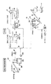
図1において、10は本発明の実施例1に係る、下水処理場の沈砂池11の底部に沈降した沈砂を洗浄する沈砂洗浄装置である。この沈砂洗浄装置10は、沈砂池11の底部から沈砂移送機12により移送された有機物や土砂を含む汚水を導入する洗浄槽13を有し、この洗浄槽13に収納され、円錐状螺旋板(傾斜板)14間の平行な螺旋状流路(隙間)14aに流入した汚水中から、有機物と土砂とを比重差を利用して重力分離するスパイラルセパレータ(傾斜板式洗砂分離機)15と、洗浄槽13内に微細気泡を含む混気水をノズル16から噴出して沈砂を洗浄する混気水製造機17と、洗浄槽13の下部から洗浄された土砂を回収する土砂回収コンベア(揚砂コンベア)18とを備え、洗浄槽13の液面付近に浮上した有機物を含む分離液を沈砂池11へ戻す装置である。
Examples of the present invention will be specifically described below.
In FIG. 1,
以下、これらの構成を具体的に説明する。
沈砂池11は、下水道幹線からの下水が直接導入される下水処理場の沈砂池である。
沈砂移送機12としては、加圧水と空気とを利用し、汚水とともに沈砂を真空吸引移送する混気ジェットポンプ方式のもの採用されている。これは、空気と加圧水とを真空吸引移送の動力としたポンプである。その他、V字バケットコンベア19により回収した沈砂を希釈水とともに送水する送砂ポンプ方式の沈砂移送機12Aを採用してもよい。これは、V字バケットコンベア19により沈砂池11の底部に沈積した沈砂を掻き揚げ、これを沈砂槽12aにいったん溜めたのち、沈砂槽12a内の沈砂を希釈水とともにサンドポンプ20により送水するものである。
Hereinafter, these configurations will be described in detail.
The sand basin 11 is a sand basin of a sewage treatment plant into which sewage from a sewer main line is directly introduced.
As the sand settling machine 12, a mixed-air jet pump system that uses pressurized water and air to suck and transfer the settling sand together with the sewage is employed. This is a pump using air and pressurized water as power for vacuum suction transfer. In addition, you may employ | adopt the sand-sink-pump type sand-
沈砂移送機12により真空吸引移送された沈砂を含む汚水は、沈砂供給管21を経て沈砂洗浄装置10の洗浄槽13へ導入される。沈砂供給管21の途中には、脱水・送泥前処理設備23の液体サイクロン24により分離された分離砂を含む汚水などが混入される。
脱水・送泥前処理設備23では、液体サイクロン24のホッパの上部周側面の一部から初沈汚泥を投入し、サイクロン24内で遠心分離された分離砂を、ホッパ下端部からスクリューコンベア25の下端部に投入する。一方、ホッパ上端部から排出された分離された汚泥は送泥井へ移送されて処理される。スクリューコンベア25の上端部に移送された分離砂は、直下の分離砂溶解タンク26へ落下する。ここでは、所定量の溶解水を供給しながら希釈タンク曝気用ブロア27からの圧縮空気をバブリングし、さらに攪拌機28による攪拌が行われる。このようにして、分離砂溶解タンク26の底部に沈降した分離砂が、分離砂移送ポンプ29により前記沈砂供給管21に導入される。
The sewage containing the sand settling by vacuum suction by the sand settling machine 12 is introduced into the
In the dewatering /
次に、図2を参照して、前記スパイラルセパレータ15を詳細に説明する。
ここでは、傾斜板式洗砂分離機として、筒状の洗浄槽13内で、螺旋状流路14aが形成された円錐状螺旋板14を、軸線が垂直な回転軸を中心として回転モータ30により回転させるスパイラルセパレータ15が採用されている。
スパイラルセパレータ15は、洗浄槽13を有する。洗浄槽13の下部は、下方へ向けて徐々に先細りとなるホッパ部31となっている。ホッパ部31の下端部には、中央砂出口32が形成されている。
Next, the
Here, as an inclined plate type sandwashing separator, a
The
洗浄槽13の円筒状壁33の上部端には、せき(ウェア)34が形成されており、せき34の周囲には、分離液(有機物を含む汚水)を回収する環状樋35が形成されている。環状樋35に流れ落ちた分離液は、図示しない分離液戻し管により沈砂池11へ戻される。
沈砂を含む汚水が流れ込む洗浄槽13の上端部中央の入口筒36の先端部は、洗浄槽13の上蓋37の中央部から洗浄槽13に侵入し、洗浄槽13の軸に向かって内側に延在する。入口筒36の周囲には、液体表面の位置より上から洗浄槽13の円筒状部のおおよそ中間まで延在する円筒状管状壁(回転軸)38が配置されている。
A cough (wear) 34 is formed at the upper end of the cylindrical wall 33 of the
The tip of the
円筒状環状壁38の外部表面は、円筒状環状壁38から下方にかつ外向きで、しかも、より合わされた螺旋状形状で円筒状環状壁38の周辺に延在する一連の円錐状螺旋板14を支持している。円錐状螺旋板14は、洗浄槽13の円筒状壁33に隣接するところで集結するように放射状に延在する。円錐状螺旋板14の傾斜、すなわち、円錐状螺旋板14の表面上の放射線と螺旋の軸との間で形成された角度は約45°で、ボルトのねじ部と同じ左巻きである。円錐状螺旋板14の回転速度および円錐状螺旋板14のピッチは、好ましくは、沈砂を含む汚水の垂直の流速(非渦巻き速度(no swirl speed))に対応して調整される。この「非渦巻き速度」において、流体は、実質的に垂直な方向で洗浄槽13を通過して流れる。
The outer surface of the cylindrical
円錐状螺旋板14と円筒状環状壁38とは、上蓋37の中央部付近に配置された回転モータ30により、洗浄槽13の軸を中心に右方向へ回転可能となっている。
入口筒36から円筒状環状壁38へ流れ込んだ沈砂を含む汚水は、円筒状環状壁38の内部空間のうち、その水面または水面付近で排出される。
沈砂を含む汚水は、その後、円筒状環状壁38の下端部に到達するまで円筒状環状壁38内を軸方向の下側に流れる。流れの方向は、ここで反転し、沈砂を含む汚水は、円錐状円錐状螺旋板14の配列を通過して上方向に流れる。
The
The sewage containing sedimentation that flows into the cylindrical
Thereafter, the sewage containing the settling sand flows downward in the axial direction in the cylindrical
沈砂を含む汚水が円錐状螺旋板14の間を上方向に通過する間に、微粒子状物質である土砂は分離され、円錐状螺旋板14の上側表面に堆積される。この土砂は、プレートの上側表面に沿って下方にかつ半径方向に外に向かって移動し、洗浄槽13の円筒状環状壁38の近傍で排出される。前記土砂は、その後、洗浄槽13のホッパ部31へ沈んで行き、中央砂出口32から排出される。このとき、混気水製造機17により発生した混気水が、ホッパ部31の周壁の一部に固定されたノズル16からホッパ部31の中央に向って噴出される。
混気水製造機17は、沈砂洗浄装置10の処理水の圧送ポンプ39と、圧縮空気を発生させる図示しないコンプレッサと、混合器(エジェクター)40とを有している。混気水の洗浄槽13内への噴出により、沈降中の比較的大きな土砂や土砂粒子を含む大きい有機物や絡まった繊維質の有機物が再び巻き上げられ、土砂の洗浄効果がさらに高まる。なお、ノズル16の噴出口の向きは、下向きが好ましいが上向きでもよい。
While the sewage containing sedimentation passes upward between the
The air-mixed water production machine 17 includes a pump for pumping treated water of the sand
洗浄槽13のホッパ部31の下端部には、洗浄槽13の下部から洗浄後の土砂を回収する土砂回収コンベア18の搬送管41の下端部が連通されている。土砂回収コンベア18は支柱42を介して傾斜配置されている。土砂回収コンベア18の下端部には、中央砂出口32と連通する開口43が形成されている。搬送管41内には、スクリュー44が回転自在に収納されている。搬送管41の上端部には、プーリ式動力伝達部を介して、スクリュー44に回転力を伝達する電動モータ45が固定されている。また、搬送管41の上端部には、回収された砂の排出口46が形成されている。この排出口46から排出された土砂は、洗砂貯留ホッパ47にいったん貯留された後、トラックの荷台に投下されて埋立地へ運送される。
The lower end of the
次に、この発明の実施例1に係る沈砂洗浄装置10の運転方法を説明する。
図1に示すように、混気ジェットポンプ方式の沈砂移送機12により、空気と加圧水とを真空吸引移送の動力とし、沈砂池11の底部に沈降した沈砂を汚水とともに、沈砂供給管21を経て沈砂洗浄装置10の洗浄槽13、具体的にはスパイラルセパレータ15の入口筒36に導入される。沈砂供給管21の途中には脱水・送泥前処理設備23の液体サイクロン24により分離された分離砂を含む汚水が混入される。
Next, an operation method of the sand
As shown in FIG. 1, air and pressurized water are used as power for vacuum suction transfer by an air-jet pump type sand settling machine 12, and the sand settling on the bottom of the sand settling basin 11 together with sewage is passed through a
前記入口筒36に導入された沈砂を含む汚水は、円筒状環状壁38の内部空間のうち、その水面または水面付近で排出される。スパイラルセパレータ15内では、沈砂を含む汚水が入口筒36から円筒状環状壁38の内部空間へ供給される。その後、沈砂を含む汚水は、円筒状環状壁38内を下り、洗浄槽13のホッパ部31へと降下する。このとき、回転モータ30により円筒状環状壁38を介して円錐状螺旋板14が右回転している。そのため、いったんホッパ部31へ向った沈砂を含む汚水は微細な土砂と有機物を含み上昇し、円錐状螺旋板14の下部の螺旋状流路14aへ流れ込む。その後、汚水は、円錐状螺旋板14の回転に伴って螺旋状流路14aに沿って上昇する。このとき、混気水製造機17により発生した混気水が、ホッパ部31の周壁の一部に固定されたノズル16からホッパ部31の中央に向って噴出される。混気水の洗浄槽13内への噴出により、そのまま沈降中の比較的大きな土砂や土砂粒子を含む大きい有機物や絡まった繊維質の有機物が再び巻き上げられ、有機物が解され浮上することで土砂の洗浄効果がさらに高まる。
The sewage containing sedimentation introduced into the
微細な土砂と有機物を含む汚水が螺旋状流路14aに沿って上昇する途中、汚水中の土砂と液分とが固液分離される。比重の軽い有機物の多くは液分と共に上昇する。固形分である土砂は円錐状螺旋板14の傾斜した表面を転がり落ち、ホッパ部31の下端部の中央砂出口32から、土砂回収コンベア18を介して巻き上げられ、洗砂貯留ホッパ47にいったん貯留された後、トラックの荷台に投下されて埋立地へ運送される。
一方、洗浄され沈砂の土砂から分離された有機物を含む分離液は、洗浄槽13の上部端付近まで上昇し、オーバーフローした分離液がせき34を越して環状樋35へ溢れ出て、前記沈砂池11へ自然落下により戻される。円錐状螺旋板14に捕捉された土砂とともに沈降した一部の有機物も、再度ノズル16から噴出される混気水により洗浄され、微細気泡が付着することでより見かけの比重が軽くなり、螺旋状流路14aを通過し、環状樋35へ溢れ出る。
While the sewage containing fine earth and sand and the organic matter rises along the spiral flow path 14a, the earth and sand in the sewage and the liquid are separated into solid and liquid. Many of the light organic substances increase with liquid content. The earth and sand, which is solid content, rolls down on the inclined surface of the
On the other hand, the separated liquid containing the organic matter that has been washed and separated from the sedimented sediment rises to the vicinity of the upper end of the
このように、洗浄槽13内に微細気泡を含む混気水をノズル16から噴出することで、沈砂に付着した有機物を洗い流す。混気水が微細気泡を含むので、沈砂中の土砂と有機物を解すことができ、かつ有機物に微細気泡を付着させることで有機物の浮上性を高め、スパイラルセパレータ15での有機物と土砂との分離性を高めることができる。しかも、微細気泡を混気水として洗浄槽13内、特にその底部にノズル16から吹き込むことで、土砂と共沈した紙繊維や髪の毛などの繊維状有機物から土砂粒子を解し取り、繊維状有機物、あるいは粗大な野菜屑やタバコのフィルターなどのし渣を再度洗い解し、流し出すことができる。
また、スパイラルセパレータ15を採用したので、汚水が円錐状螺旋板14間の平行な螺旋状流路14aに流入した際、土砂と有機物の沈降速度差をつけ、比重差を利用して効率よく重力分離することができる。これにより、汚水に含まれる土砂の高回収率と、汚土砂に含まれる有機物の高除去率とを同時に得ることができる。
As described above, the mixed water containing fine bubbles is ejected from the
In addition, since the
混気ジェットポンプ方式の沈砂移送機12および混気ジェットポンプ方式の沈砂移送機を採用したので、多量の希釈水と共に汚水として送水されることで、送水管内で予め土砂と有機物が分散される効果が得られる。
また、傾斜板式洗砂分離機15としてスパイラルセパレータ15を採用したので、上向流と微細気泡を円錐状螺旋板14全体で均一に受けることができる。これにより、洗砂槽全体への混気水噴出ノズルによる攪拌力を抑え、気泡による上向偏流をなくし、最適な回転により流れを乱さず傾斜板群内に処理対象液を呼び込むことで、傾斜板群下を混気水で攪拌しつつ高い分離性を維持できるという効果が得られる。
また、傾斜板全体で高い分離効率を得ることができるとともに、微細気泡により発生する上向偏流を抑え、有機物に付着しない余分な気泡は円筒状環状壁38へ集め、収集孔から円筒状環状壁38内部に取り込むことで、螺旋状流路14a内での水流の乱れを無くす効果が得られる。
さらに、液体サイクロン24により分離された分離砂を、沈砂移送機12により移送中の汚水中に混入するようにしたので、別途、希釈水を必要とせずに処理が可能である。また、従来、ほとんどの分離砂中の土砂は洗砂槽から流出し、下水処理場内を循環していたが、分離砂中の土砂の回収率を高めることで循環量を減らし、液体サイクロンへの負荷を低減することで汚泥濃縮装置のトラブルや送泥管やピットへの土砂堆積が減る。すなわち沈砂池で捕捉されず通過した200μm以下の微細な土砂も同時に洗浄・回収することが可能となり、沈砂池11と最初沈澱池を経由し液体サイクロン24へ再度戻る200μm以下の微細な土砂も少なくすることができる。このため液体サイクロン24から汚泥とともに送泥井へ移送される土砂量が減り、送泥管やピットに堆積する土砂を低減できる効果が得られる。
Since the mixed-air jet pump type sand settling machine 12 and the mixed-air jet pump type sand settling machine are adopted, the soil and organic matter are dispersed in advance in the water supply pipe by being fed as sewage with a large amount of diluted water. Is obtained.
Further, since the
In addition, it is possible to obtain high separation efficiency with the entire inclined plate, suppress upward drift caused by fine bubbles, and collect excess bubbles that do not adhere to organic matter to the cylindrical
Furthermore, since the separated sand separated by the liquid cyclone 24 is mixed into the sewage being transferred by the sand settling machine 12, it can be processed without requiring separate dilution water. In the past, most of the sediment in the separated sand flowed out of the sand-washing tank and circulated in the sewage treatment plant.However, by increasing the recovery rate of the sediment in the separated sand, the circulation rate was reduced and the liquid cyclone was recycled. By reducing the load, troubles in the sludge concentrator and sediment accumulation in the mud pipe and pit are reduced. In other words, it becomes possible to simultaneously wash and collect the fine sediment of 200 μm or less that has passed without being captured by the sedimentation basin, and there is little fine sediment of 200 μm or less that returns to the hydrocyclone 24 again through the sedimentation basin 11 and the first sedimentation basin. can do. For this reason, the amount of earth and sand transferred from the hydrocyclone 24 to the mud well with the sludge is reduced, and the effect of reducing the earth and sand accumulated in the mud pipe and the pit can be obtained.
10 沈砂洗浄装置
11 沈砂池
12 沈砂移送機
12A 送砂ポンプ方式の沈砂移送機
13 洗浄槽
14 円錐状螺旋板(傾斜板)
14a 螺旋状流路(隙間)
15 スパイラルセパレータ(回転傾斜板式沈降分離機)
16 ノズル
17 混気水製造機
18 土砂回収コンベア
19 バケットコンベア
23 脱水・送泥前処理設備
24 液体サイクロン
30 回転モータ(回転手段)
DESCRIPTION OF
14a Spiral channel (gap)
15 Spiral separator (rotating inclined plate type sedimentation separator)
16 Nozzle 17 Mixed Water Production Machine 18
Claims (6)
該洗浄槽に収納され、傾斜板間の平行な隙間に流入した前記汚水中から、前記有機物と前記土砂とを比重差を利用して重力分離する傾斜板式洗砂分離機と、
前記洗浄槽内に微細気泡を含む混気水をノズルから噴出して前記土砂を洗浄する混気水製造機と、
前記洗浄槽の下部から洗浄された土砂を回収する土砂回収コンベアとを備え、
前記洗浄槽の液面付近に浮上した有機物を含む分離液を前記沈砂池へ戻す管路を設けたこと特徴とした沈砂洗浄装置。 It has a washing tank that introduces sewage containing organic matter and earth and sand transferred from the bottom of the sand settling basin by a sand settling machine,
An inclined plate type sandwashing machine that gravity-separates the organic matter and the earth and sand from the sewage that is stored in the washing tank and flows into parallel gaps between the inclined plates using a difference in specific gravity,
An air-mixed water producing machine for cleaning the earth and sand by jetting air-mixed water containing fine bubbles in the cleaning tank;
A sediment collection conveyor for collecting the washed soil from the lower part of the washing tank,
A sand sediment washing apparatus comprising a pipe for returning a separation liquid containing an organic substance floating near the liquid surface of the washing tank to the sand settling basin.
Priority Applications (1)
| Application Number | Priority Date | Filing Date | Title |
|---|---|---|---|
| JP2008264778A JP5067809B2 (en) | 2008-10-14 | 2008-10-14 | Sand settling equipment |
Applications Claiming Priority (1)
| Application Number | Priority Date | Filing Date | Title |
|---|---|---|---|
| JP2008264778A JP5067809B2 (en) | 2008-10-14 | 2008-10-14 | Sand settling equipment |
Publications (2)
| Publication Number | Publication Date |
|---|---|
| JP2010094568A true JP2010094568A (en) | 2010-04-30 |
| JP5067809B2 JP5067809B2 (en) | 2012-11-07 |
Family
ID=42256642
Family Applications (1)
| Application Number | Title | Priority Date | Filing Date |
|---|---|---|---|
| JP2008264778A Active JP5067809B2 (en) | 2008-10-14 | 2008-10-14 | Sand settling equipment |
Country Status (1)
| Country | Link |
|---|---|
| JP (1) | JP5067809B2 (en) |
Cited By (5)
| Publication number | Priority date | Publication date | Assignee | Title |
|---|---|---|---|---|
| JP2011056487A (en) * | 2009-09-07 | 2011-03-24 | Sanei:Kk | Cleaning treatment method and apparatus |
| JP2012050946A (en) * | 2010-09-02 | 2012-03-15 | Sumitomo Heavy Industries Environment Co Ltd | System for separating precipitated sand |
| JP2012200645A (en) * | 2011-03-24 | 2012-10-22 | Sumitomo Heavy Industries Environment Co Ltd | Separator for sedimented sand |
| JP2013059755A (en) * | 2011-09-15 | 2013-04-04 | Mitsubishi Kakoki Kaisha Ltd | Grit cleaning apparatus |
| CN114904827A (en) * | 2022-05-14 | 2022-08-16 | 洛阳隆中重工机械有限公司 | High-efficient ore sand desliming equipment |
Citations (5)
| Publication number | Priority date | Publication date | Assignee | Title |
|---|---|---|---|---|
| JPS5584152U (en) * | 1978-12-07 | 1980-06-10 | ||
| JPS60216813A (en) * | 1984-03-28 | 1985-10-30 | Hitachi Metals Ltd | Method for conveying and storing grit |
| JPH0214761A (en) * | 1988-07-01 | 1990-01-18 | Marusei Jukogyo Kk | Method and device for cleaning grit and scum of grit chamber |
| JP2004275182A (en) * | 2003-02-28 | 2004-10-07 | Shikoku Chuboki Seizo Kk | Apparatus and method for eliminating foreign matter from nemacystus decipiens |
| JP2006198605A (en) * | 2004-12-24 | 2006-08-03 | Hitachi Kiden Kogyo Ltd | Sand separating and washing apparatus |
-
2008
- 2008-10-14 JP JP2008264778A patent/JP5067809B2/en active Active
Patent Citations (5)
| Publication number | Priority date | Publication date | Assignee | Title |
|---|---|---|---|---|
| JPS5584152U (en) * | 1978-12-07 | 1980-06-10 | ||
| JPS60216813A (en) * | 1984-03-28 | 1985-10-30 | Hitachi Metals Ltd | Method for conveying and storing grit |
| JPH0214761A (en) * | 1988-07-01 | 1990-01-18 | Marusei Jukogyo Kk | Method and device for cleaning grit and scum of grit chamber |
| JP2004275182A (en) * | 2003-02-28 | 2004-10-07 | Shikoku Chuboki Seizo Kk | Apparatus and method for eliminating foreign matter from nemacystus decipiens |
| JP2006198605A (en) * | 2004-12-24 | 2006-08-03 | Hitachi Kiden Kogyo Ltd | Sand separating and washing apparatus |
Cited By (5)
| Publication number | Priority date | Publication date | Assignee | Title |
|---|---|---|---|---|
| JP2011056487A (en) * | 2009-09-07 | 2011-03-24 | Sanei:Kk | Cleaning treatment method and apparatus |
| JP2012050946A (en) * | 2010-09-02 | 2012-03-15 | Sumitomo Heavy Industries Environment Co Ltd | System for separating precipitated sand |
| JP2012200645A (en) * | 2011-03-24 | 2012-10-22 | Sumitomo Heavy Industries Environment Co Ltd | Separator for sedimented sand |
| JP2013059755A (en) * | 2011-09-15 | 2013-04-04 | Mitsubishi Kakoki Kaisha Ltd | Grit cleaning apparatus |
| CN114904827A (en) * | 2022-05-14 | 2022-08-16 | 洛阳隆中重工机械有限公司 | High-efficient ore sand desliming equipment |
Also Published As
| Publication number | Publication date |
|---|---|
| JP5067809B2 (en) | 2012-11-07 |
Similar Documents
| Publication | Publication Date | Title |
|---|---|---|
| CN102718375B (en) | Oily sediment treatment method and device | |
| KR101729262B1 (en) | Adulteration disposal equipment with wedge bar screen | |
| JP5916005B2 (en) | Sand settling device | |
| KR102141236B1 (en) | Various dredged soil purification system | |
| JP5067809B2 (en) | Sand settling equipment | |
| US20140190897A1 (en) | Enhanced separation of nuisance materials from wastewater | |
| KR101782615B1 (en) | Contaminated soil remediation system and remediation method having the same | |
| CN202729965U (en) | Oil field skid-mounted type oil field waste treatment device | |
| KR102081851B1 (en) | Vortex type Combined Screening and Grit Removal system having a scum removal device | |
| CN211097707U (en) | Fine sand recovery device and concrete waste recovery processing system | |
| KR101431161B1 (en) | Filtering, dehydrating equipment of sand and impurities | |
| JP2009268954A (en) | Solid-liquid separation/washing apparatus and solid-liquid separation/washing system using the same | |
| CN106830594B (en) | Sludge treatment system | |
| JP2004216258A (en) | Treatment system for oil-contaminated soil, treatment device and treatment method | |
| CN201882993U (en) | Oily sewage settling treatment device | |
| JP4794605B2 (en) | Solid-liquid separation cleaning system | |
| CN102583674B (en) | Integrated oily mud wastewater pipe bundle coagulation and separation reactor | |
| CN206607098U (en) | One kind cleaning HDPE reclaimed materials sewage disposal systems | |
| KR900006074B1 (en) | Method and apparatus for seperating solids from liquids | |
| CN211885784U (en) | Mortar pump type fine sand recovery equipment | |
| JP2006095413A (en) | Sand separation/washing device | |
| NZ546587A (en) | Grit trap | |
| GB2457068A (en) | Aggregate washing apparatus | |
| JP4230366B2 (en) | Oil recovery unit | |
| KR20210023274A (en) | Integrated waste water treatment tank facility for wet type sand product plant |
Legal Events
| Date | Code | Title | Description |
|---|---|---|---|
| A621 | Written request for application examination |
Free format text: JAPANESE INTERMEDIATE CODE: A621 Effective date: 20110519 |
|
| A977 | Report on retrieval |
Free format text: JAPANESE INTERMEDIATE CODE: A971007 Effective date: 20120521 |
|
| A131 | Notification of reasons for refusal |
Free format text: JAPANESE INTERMEDIATE CODE: A131 Effective date: 20120530 |
|
| A521 | Request for written amendment filed |
Free format text: JAPANESE INTERMEDIATE CODE: A523 Effective date: 20120719 |
|
| TRDD | Decision of grant or rejection written | ||
| A01 | Written decision to grant a patent or to grant a registration (utility model) |
Free format text: JAPANESE INTERMEDIATE CODE: A01 Effective date: 20120808 |
|
| A01 | Written decision to grant a patent or to grant a registration (utility model) |
Free format text: JAPANESE INTERMEDIATE CODE: A01 |
|
| A61 | First payment of annual fees (during grant procedure) |
Free format text: JAPANESE INTERMEDIATE CODE: A61 Effective date: 20120808 |
|
| FPAY | Renewal fee payment (event date is renewal date of database) |
Free format text: PAYMENT UNTIL: 20150824 Year of fee payment: 3 |
|
| R150 | Certificate of patent or registration of utility model |
Ref document number: 5067809 Country of ref document: JP Free format text: JAPANESE INTERMEDIATE CODE: R150 Free format text: JAPANESE INTERMEDIATE CODE: R150 |
|
| R250 | Receipt of annual fees |
Free format text: JAPANESE INTERMEDIATE CODE: R250 |
|
| R250 | Receipt of annual fees |
Free format text: JAPANESE INTERMEDIATE CODE: R250 |
|
| R250 | Receipt of annual fees |
Free format text: JAPANESE INTERMEDIATE CODE: R250 |
|
| R250 | Receipt of annual fees |
Free format text: JAPANESE INTERMEDIATE CODE: R250 |
|
| R250 | Receipt of annual fees |
Free format text: JAPANESE INTERMEDIATE CODE: R250 |
|
| R250 | Receipt of annual fees |
Free format text: JAPANESE INTERMEDIATE CODE: R250 |
|
| R250 | Receipt of annual fees |
Free format text: JAPANESE INTERMEDIATE CODE: R250 |
|
| R250 | Receipt of annual fees |
Free format text: JAPANESE INTERMEDIATE CODE: R250 |
|
| R250 | Receipt of annual fees |
Free format text: JAPANESE INTERMEDIATE CODE: R250 |
|
| R250 | Receipt of annual fees |
Free format text: JAPANESE INTERMEDIATE CODE: R250 |