JP2010094271A - Toilet seat device - Google Patents

Toilet seat device Download PDF

Info

Publication number
JP2010094271A
JP2010094271A JP2008267313A JP2008267313A JP2010094271A JP 2010094271 A JP2010094271 A JP 2010094271A JP 2008267313 A JP2008267313 A JP 2008267313A JP 2008267313 A JP2008267313 A JP 2008267313A JP 2010094271 A JP2010094271 A JP 2010094271A
Authority
JP
Japan
Prior art keywords
toilet seat
pivot
shaft
mounting portion
support
Prior art date
Legal status (The legal status is an assumption and is not a legal conclusion. Google has not performed a legal analysis and makes no representation as to the accuracy of the status listed.)
Pending
Application number
JP2008267313A
Other languages
Japanese (ja)
Inventor
Hiroshi Matsuda
宏 松田
Yoshikazu Kobayashi
由和 小林
Current Assignee (The listed assignees may be inaccurate. Google has not performed a legal analysis and makes no representation or warranty as to the accuracy of the list.)
Inax Corp
Original Assignee
Inax Corp
Priority date (The priority date is an assumption and is not a legal conclusion. Google has not performed a legal analysis and makes no representation as to the accuracy of the date listed.)
Filing date
Publication date
Application filed by Inax Corp filed Critical Inax Corp
Priority to JP2008267313A priority Critical patent/JP2010094271A/en
Publication of JP2010094271A publication Critical patent/JP2010094271A/en
Pending legal-status Critical Current

Links

Images

Landscapes

  • Toilet Supplies (AREA)

Abstract

<P>PROBLEM TO BE SOLVED: To control backlash of a toilet seat 2 in the direction of shaft center Y2 of the toilet seat. <P>SOLUTION: The toilet seat device has one pivotally supporting part X1 and another pivotally supporting part X2 for pivotally supporting the toilet seat 2 to a support body 6 in such a way as swingable via both attaching arms 4 and 5. The another pivotally supporting part X2 has a toilet seat transfer regulating part 39 to regulate the transfer of the attached toilet seat 2 in one direction (to the right side) to a regulated position Q. The one pivotally supporting part X1 includes: a pivot 10 projecting from a swelling part 7; a bearing part 13 disposed in one attaching arm 4 and having a shaft mounting part 13a and one pivot inserting/extracting opening 13b for inserting/extracting the pivot 10 into/from the shaft mounting part 13a; and a pressing means 40 for pressing the shaft mounting part 13a with the inserted pivot 10 passing through the pivot inserting/extracting opening 13b toward the projection distal end side of the pivot 10. The toilet seat 2 is moved to the regulated position Q or close to the regulated position Q by pressing the shaft mounting part 13a by the pressing means 40. <P>COPYRIGHT: (C)2010,JPO&INPIT

Description

本発明は、便器本体に取付ける支持体に便座を着脱ができる便座装置に関するものである。   The present invention relates to a toilet seat device in which a toilet seat can be attached to and detached from a support attached to a toilet bowl body.

従来、便座を着脱に取り付ける便座取付構造は、便器に固定される固定部材と、固定部材に一対に設けられて対向する穴を備えた軸支持体と、便座軸を備えて軸支持体に回動自在に軸支される便座と、固定部材に装着されるカバーにて構成され、便座軸と穴との間には便座を便座軸の軸芯方向(以下、「便座軸芯方向」という。)へ摺動することにより固定部材から着脱自在とするための隙間を設け、カバーには便座を便座軸芯方向へ摺動するのを規制する摺動規制手段を備えたものがある(特許文献1)。
特開2003−265361号
Conventionally, a toilet seat mounting structure for detachably mounting a toilet seat includes a fixing member that is fixed to the toilet, a shaft support that is provided with a pair of opposed holes in the fixing member, and a shaft support that includes a toilet seat shaft. The toilet seat is composed of a movably supported toilet seat and a cover attached to the fixed member. The toilet seat is referred to as an axial direction of the toilet seat shaft (hereinafter referred to as “toilet seat axial direction”). ) Is provided so as to be detachable from the fixing member, and there is a cover provided with sliding restriction means for restricting the toilet seat from sliding in the axial direction of the toilet seat (Patent Document) 1).
JP 2003-265361 A

ところで、従来の便座取付構造は、固定部材に設けられた一対の軸支持体の穴と便座軸との間に着脱自在とするための隙間が設けられているので、穴に便座軸を挿着しただけでは便座が便座軸芯方向へ摺動して脱落することがあり、便座軸芯方向へ便座が摺動するのを規制するカバーを固定部材に装着する必要がある。そのため、従来の便座取付構造は、大きなカバーを着脱するために多くの手間を要すると共に、カバーの規制を受ける所定位置に便座を配置しつつ固定部材にカバーを装着するのに注意を要し、もしカバーの装着が不完全であると便座の脱落や、便座軸芯方向への便座のガタ付きを招くことがある。   By the way, in the conventional toilet seat mounting structure, since a clearance is provided between the hole of the pair of shaft supports provided on the fixing member and the toilet seat shaft, the toilet seat shaft is inserted into the hole. If only the toilet seat is slid in the axial direction of the toilet seat and falls off, it is necessary to attach a cover that restricts the sliding of the toilet seat in the axial direction of the toilet seat to the fixing member. Therefore, the conventional toilet seat mounting structure requires a lot of labor to attach and detach a large cover, and requires attention to mount the cover on the fixing member while placing the toilet seat at a predetermined position subject to the restriction of the cover, If the cover is incompletely attached, the toilet seat may fall off or the toilet seat may rattle in the axial direction of the toilet seat.

本発明は、便座の摺動を規制するカバーを用いることなく、便座軸芯方向への便座のガタ付きを抑制できる便座装置の提供を目的とする。   An object of this invention is to provide the toilet seat apparatus which can suppress the backlash of the toilet seat to the toilet seat axial direction, without using the cover which controls sliding of a toilet seat.

便座軸芯方向への便座のガタ付きを抑制できるように請求項1記載の本発明が採用した手段は、着座面を形成した本体部に左右の一方の取付用腕部と左右の他方の取付用腕部を突設した便座と、両方の取付用腕部で挟まれる膨出部を形成した支持体と、支持体に両方の取付用腕部を介して便座を揺動自在に枢支する一方の枢支部及び他方の枢支部とを備え、便座が支持体に対し着脱可能である便座装置において、他方の枢支部は、装着する便座の一方側へ向かう移動を規制位置までとする便座移動規制部が形成され、一方の枢支部は、膨出部から突出する一方枢軸と、一方の取付用腕部に設けられ、軸装部及び軸装部へ一方枢軸を出し入れするための一方枢軸出入用開口部を有する一方軸受部と、一方枢軸出入用開口部を通過させて一方枢軸を入れた軸装部を一方枢軸の突出先端側へ向かって押圧する押圧手段とを備え、軸装部を押圧手段で押圧することで、便座を規制位置又は規制位置の近傍まで移動させるようにしたことを特徴とする便座装置である。   The means adopted by the present invention according to claim 1 to prevent the backlash of the toilet seat in the toilet seat axial direction is that the left and right attachment arm portions and the left and right other attachment portions are attached to the body portion on which the seating surface is formed. The toilet seat is provided with a protruding arm portion, a support member having a bulging portion sandwiched between both attachment arm portions, and the toilet seat is pivotally supported on the support member via both attachment arm portions. In a toilet seat device having one pivotal support part and the other pivotal support part, wherein the toilet seat is detachable from the support body, the other pivotal support part moves the toilet seat toward one side of the toilet seat to be mounted up to the restriction position. A restricting portion is formed, and one pivot support portion is provided on one pivot shaft projecting from the bulging portion and one mounting arm portion, and the one pivot shaft entry / exit for inserting / removing the one pivot shaft to / from the shaft mounting portion One bearing part with an opening for use, and one pivot through the one pivot entry / exit opening And a pressing means for pressing the inserted shaft mounting portion toward the projecting tip side of the one pivot, and the toilet seat is moved to the restriction position or the vicinity of the restriction position by pressing the shaft mounting part with the pressing means. This is a toilet seat device.

他方の枢支部における便座の着脱が簡単且つ確実にできるようにするために請求項2記載の本発明が採用した手段は、前記他方の枢支部は、膨出部及び他方の取付用腕部のいずれか一方から突出する他方枢軸と、これらの他方に開設した嵌挿用凹部へ他方枢軸を出入れできる他方軸受部とを備え、この他方軸受部は、便座枢支の中心となる支持体の支持体軸芯と分離状態の便座の便座軸芯との交差角を大きくした便座傾斜姿勢のまま他方枢軸を受け入れでき、他方枢軸を受け入れたまま両軸芯の交差角を小さくさせる便座傾斜姿勢を経て両軸芯を合致させる便座接合姿勢へ移行させるのに伴い、前記一方枢軸が一方枢軸出入用開口部を通過して軸装部へ入ることができるように、嵌挿用凹部の奥側に比べて開口端側を大径に形成した請求項1に記載の便座装置である。   In order that the toilet seat can be easily and reliably attached to and detached from the other pivotal support portion, the means adopted by the present invention according to claim 2 is characterized in that the other pivotal support portion includes the bulging portion and the other mounting arm portion. The other pivot that protrudes from one of the two and the other bearing that allows the other pivot to be inserted into and retracted from the recess for insertion that is provided on the other of the pivots. Toilet seat tilt posture that can accept the other pivot while maintaining the tilt angle of the toilet seat with the increased intersection angle between the support shaft core and the toilet seat shaft core of the separated toilet seat, and reduces the intersection angle of both shaft cores while receiving the other pivot axis As a result of the transition to the toilet seat joint posture in which the two shaft cores are matched, the one pivot is placed on the back side of the recess for insertion so that the one pivot can enter the shaft mounting part through the one pivot access opening. The opening end side is formed to have a larger diameter than that of claim 1. A toilet seat apparatus according.

なお、請求項2に記載の前記他方軸受部は、嵌挿用凹部の奥側突き当たりに、前記両軸芯を大きく交差させる便座傾斜姿勢のまま他方枢軸を受け入れるときに他方枢軸の一方側外隅部を侵入させる侵入用空間部と、前記両軸芯を小さく交差させる便座傾斜姿勢を経て両軸芯を合致させる便座接合姿勢へ移行させるのに伴い傾動する他方枢軸の先端面を当接させて一方側外隅部を侵入用空間部から引き出させる引出し面とを設けることで、両軸芯を小さく交差させる便座傾斜姿勢を経て両軸芯を合致させる便座接合姿勢へ移行させるのに伴い傾動する他方枢軸の一方側外隅部を侵入用空間部から引き出させて他方枢軸の先端面を引出し面に当接させることで、引き出させた分だけ便座軸芯方向に沿う移動を減少させるので、装着状態の便座の便座軸芯方向に沿うガタ付きを小さくすることができるようになる。   The other bearing portion according to claim 2 is configured such that when the other pivot is received in the toilet seat tilt posture in which the two shaft cores are largely intersected at the rear end of the insertion recess, the one outer corner of the other pivot is received. The intrusion space part that intrudes the part and the distal end surface of the other pivot that is tilted as a result of the transition to the toilet seat jointing posture that matches both shaft cores through the toilet seat tilting posture that slightly intersects both shaft cores By providing a pull-out surface that pulls out the outer corner on one side from the intrusion space, it tilts as it shifts to a toilet seat joint posture that matches both shaft cores through a toilet seat tilt posture that crosses both shaft cores slightly. Since the outer corner of one side of the other pivot is pulled out of the space for entry and the tip surface of the other pivot is brought into contact with the drawer surface, movement along the toilet seat axial direction is reduced by the amount pulled out. Toilet seat in state It is possible to reduce the looseness along the axial direction.

一方の枢支部に便座揺動用モータの回転出力を便座へ伝達する機構を簡単に組み込むために請求項3記載の本発明が採用した手段は、前記押圧手段は、便座揺動用モータの回転出力軸で形成した一方枢軸に固着され、便座接合姿勢のときに軸装部へ入ってモータ回転出力を軸装部へ伝達する伝動具と、一方枢軸に摺動自在に外嵌され、便座接合姿勢のときに軸装部へ入る移動具と、伝動具と移動具の間に配置されたバネとを備え、移動具を介してバネ力で軸装部を押圧する請求項1又は2記載の便座装置である。   In order to easily incorporate a mechanism for transmitting the rotation output of the toilet seat swing motor to the toilet seat in one pivotal support portion, the means employed by the present invention according to claim 3 is characterized in that the pressing means is a rotation output shaft of the toilet seat swing motor. A transmission device that is fixed to the one pivot formed in the above, and that enters the shaft mounting portion when the toilet seat is in the posture of joining the toilet seat, and transmits the motor rotation output to the shaft mounting portion. The toilet seat device according to claim 1 or 2, further comprising a moving tool that sometimes enters the shaft mounting section, and a spring disposed between the transmission tool and the moving tool, and pressing the shaft mounting section with a spring force through the moving tool. It is.

一方の枢支部に便座揺動用モータの回転出力を便座へ伝達する機構を簡単に組み込むために請求項4記載の本発明が採用した手段は、前記押圧手段は、便座揺動用モータの回転出力軸で形成した一方枢軸に摺動自在に外嵌され、一方枢軸と一緒に回転する中空軸と、中空軸に固着され、便座接合姿勢のときに軸装部へ入ってモータ回転出力を軸装部へ伝達する伝動具と、一方枢軸に外嵌され、一端を膨出部側に固定すると共に他端を中空軸に当接するバネとを備え、伝動具を介してバネ力で軸装部を押圧する請求項1又は2記載の便座装置である。   In order to easily incorporate a mechanism for transmitting the rotation output of the toilet seat swinging motor to the toilet seat in one of the pivots, the means employed by the present invention according to claim 4 is characterized in that the pressing means is a rotation output shaft of the toilet seat swinging motor. A hollow shaft that is slidably fitted to the one pivot formed in the above, and rotates together with the one pivot, and is fixed to the hollow shaft, and enters the shaft mounting portion when the toilet seat is in the posture of joining the toilet seat. And a spring that is externally fitted to one pivot and has one end fixed to the bulging portion and the other end abutting against the hollow shaft, and presses the shaft mounting portion with a spring force through the transmission The toilet seat device according to claim 1 or 2.

便座揺動用モータを備えないときに押圧手段を一方の枢支部へ簡単に組み込むために請求項5記載の本発明が採用した手段は、前記押圧手段は、固定した一方枢軸に摺動自在に外嵌された中空軸と、中空軸に固着され、便座接合姿勢のときに軸装部へ入る移動具と、一方枢軸に外嵌され、一端を膨出部側に固定すると共に他端を中空軸に当接するバネとを備え、移動具を介してバネ力で軸装部を押圧する請求項1又は2記載の便座装置である。   In order to easily incorporate the pressing means into one of the pivotal support portions when the toilet seat swinging motor is not provided, the means adopted by the present invention according to claim 5 is characterized in that the pressing means is slidably mounted on the fixed one pivot. The fitted hollow shaft, the moving tool that is fixed to the hollow shaft and enters the shaft mounting portion when in the toilet seat joint posture, and is externally fitted to one pivot, and fixes one end to the bulging portion and the other end to the hollow shaft. The toilet seat device according to claim 1, further comprising a spring abutting on the shaft and pressing the shaft mounting portion with a spring force through the moving tool.

一方の枢支部における便座の装着が確実にできるようにするために請求項6記載の本発明が採用した手段は、前記一方の枢支部は、軸装部から一方枢軸が出るのを防ぐ軸抜け防止手段を備えた請求項1乃至5のいずれか1項に記載の便座装置である。   In order to ensure that the toilet seat can be mounted on one pivot part, the means adopted by the present invention according to claim 6 is that the one pivot part prevents the one pivot from coming out of the shaft mounting part. It is a toilet seat apparatus of any one of Claim 1 thru | or 5 provided with the prevention means.

軸抜け防止手段の操作を容易とするために請求項7記載の本発明が採用した手段は、前記軸抜け防止手段は、一方の取付用腕部に移動自在に設けたロック具を有し、ロック具を軸装部から一方枢軸が出ることを防止しない待機位置から防止するロック位置まで移動させるようにした請求項6記載の便座装置である。   In order to facilitate the operation of the shaft slip-off preventing means, the means adopted by the present invention according to claim 7 is characterized in that the shaft slip-off preventing means has a lock tool provided movably on one mounting arm portion, The toilet seat device according to claim 6, wherein the lock device is moved from a standby position where the one pivot is prevented from coming out of the shaft mounting portion to a lock position where the lock is prevented.

便座に設けた電気式加熱手段に対してコードレスで且つ安定して給電できるように請求項8記載の本発明が採用した手段は、前記支持体に設けた制御部と、前記支持体における他方軸受部より奥側に設けて制御部に接続した一次コイルと、便座に設けた電気式加熱手段と、前記他方枢軸に設けて加熱手段に接続した二次コイルとからなり、両コイル間の電磁誘導で給電を行うようにした給電装置を備えた請求項2に記載の便座装置である。   The means adopted by the present invention according to claim 8 so that the electric heating means provided in the toilet seat can be fed cordlessly and stably is the control unit provided in the support and the other bearing in the support. An electromagnetic induction between the two coils, comprising a primary coil provided on the back side of the unit and connected to the control unit; an electric heating means provided on the toilet seat; and a secondary coil provided on the other pivot and connected to the heating means. The toilet seat device according to claim 2, further comprising a power feeding device configured to perform power feeding at the point.

便座に設けた電気式加熱手段に対してコードレスで且つ安定して給電できるように請求項9記載の本発明が採用した手段は、前記支持体に設けた制御部と、前記支持体における他方枢軸に設けて制御部に接続した一次コイルと、便座に設けた電気式加熱手段と、前記他方軸受部より奥側に設けて加熱手段に接続した二次コイルとからなり、両コイル間の電磁誘導で給電を行うようにした給電装置を備えた請求項2に記載の便座装置である。   The means adopted by the present invention according to claim 9 to provide a cordless and stable power supply to the electric heating means provided on the toilet seat includes a control unit provided on the support and the other pivot on the support. A primary coil connected to the control unit, an electric heating means provided on the toilet seat, and a secondary coil provided on the back side of the other bearing part and connected to the heating means, and electromagnetic induction between the two coils The toilet seat device according to claim 2, further comprising a power feeding device configured to perform power feeding at the point.

なお、前記他方の枢支部における便座の装着が簡単にできるようにするために前記他方の枢支部は、膨出部の他方側から突出する他方枢軸と、他方の取付用腕部に設けられ、他方枢軸用軸装部及びこの軸装部へ他方枢軸を便座着脱時に出し入れするための他方枢軸出入用開口部を有する他方軸受部とを備えることもある。また、前記他方の枢支部における便座の装着が確実にできるようにするために前記他方の枢支部は、軸装部から一方枢軸が出るのを防ぐ軸抜け防止手段を備えることもある。更に、前記他方の枢支部における上記軸抜け防止手段の操作を容易とするために上記軸抜け防止手段は、他方の取付用腕部に移動自在に設けたロック具を有し、ロック具を軸装部から他方枢軸が出ることを防止しない待機位置から防止するロック位置まで移動させるようにすることもある。   In order to facilitate the mounting of the toilet seat on the other pivot part, the other pivot part is provided on the other pivot projecting from the other side of the bulging part and the other mounting arm part, There may be provided a shaft mounting portion for the other pivot and another bearing portion having an opening for entering and exiting the other pivot for taking the shaft into and out of the shaft mounting portion when the toilet seat is attached and detached. Further, in order to ensure that the toilet seat can be mounted on the other pivotal support part, the other pivotal support part may be provided with a shaft slip-off preventing means for preventing one pivot from coming out of the shaft mounting part. Further, in order to facilitate the operation of the shaft slip-off preventing means in the other pivotal support portion, the shaft slip-off preventing means has a lock tool provided movably on the other mounting arm portion, and the lock tool is pivoted. The other pivot may be moved from the stand-by position where it is prevented from coming out of the mounting portion to the locked position where it is prevented.

請求項1記載の本発明に係る便座装置は、一方枢軸が一方枢軸出入用開口部を通過して軸装部へ入り又は出ることで便座の着脱ができ、便座を装着するときに、一方枢軸を入れた軸装部を一方枢軸の突出先端側へ向かって押圧手段で押圧することで、便座を規制位置又は規制位置の近傍まで移動させて、便座軸芯方向に沿った便座のガタ付きを抑制できる。   The toilet seat device according to the first aspect of the present invention can be attached to or detached from the toilet seat when the one pivot passes through the one pivot entry / exit opening and enters or exits the shaft mounting portion. The toilet seat is moved to the restricting position or the vicinity of the restricting position by pressing the shaft mounting part into which the pivot is placed toward the protruding front end side of the one pivot, and the toilet seat is rattled along the toilet seat axial direction. Can be suppressed.

請求項2記載の本発明に係る便座装置は、分離した便座を装着するときには、支持体軸芯と便座軸芯を大きく交差させた便座傾斜姿勢のまま他方枢軸を他方軸受部の嵌挿用凹部の奥側へ挿入した後に、両軸芯を小さく交差させる便座傾斜姿勢を経て両軸芯を合致させるように移行させることで、一方枢軸が一方枢軸出入用開口部を通過して軸装部へ入って便座装着ができ、便座を分離するときには、上記操作と逆の操作を行うことで、両軸芯を大きく交差させた便座傾斜姿勢のまま他方枢軸を他方軸受部の嵌挿用凹部の奥側から抜き出して便座分離ができるため、便座の着脱が簡単且つ確実にできる。   In the toilet seat device according to the second aspect of the present invention, when the separated toilet seat is mounted, the other pivot is inserted into the recess of the other bearing portion while maintaining the toilet seat tilt posture in which the support shaft axis and the toilet seat axis are largely intersected. After being inserted into the back of the shaft, it is moved so that both shaft cores are matched through a toilet seat tilting posture in which both shaft cores intersect slightly, so that one pivot passes through one pivot access opening to the shaft mounting section. When the toilet seat can be installed and the toilet seat is separated, the reverse operation of the above operation is performed, so that the other pivot is placed in the back of the recess for insertion of the other bearing portion while the toilet seat is tilted with the two shaft cores largely intersecting. Since the toilet seat can be separated from the side, the toilet seat can be attached and detached easily and reliably.

請求項3記載の本発明に係る便座装置は、押圧手段が、便座揺動用モータの回転出力軸で形成した一方枢軸に固着された伝動具と、一方枢軸に摺動自在に外嵌された移動具と、伝動具と移動具の間に配置されたバネとからなるため、一方の枢支部に便座揺動用モータの回転出力を便座へ伝達する機構を簡単に組み込むことができる。   According to a third aspect of the present invention, there is provided a toilet seat device, wherein the pressing means includes a transmission member fixed to one pivot formed by a rotation output shaft of a toilet seat swinging motor, and a movement slidably fitted to the first pivot. And a spring disposed between the transmission tool and the moving tool, a mechanism for transmitting the rotation output of the toilet seat swinging motor to the toilet seat can be easily incorporated into one pivotal support portion.

請求項4記載の本発明に係る便座装置は、押圧手段が、便座揺動用モータの回転出力軸で形成した一方枢軸に摺動自在に外嵌された中空軸と、中空軸に固着された伝動具と、一方枢軸に外嵌されたバネとからなるため、一方の枢支部に便座揺動用モータの回転出力を便座へ伝達する機構を簡単に組み込むことができる。   The toilet seat device according to the present invention as set forth in claim 4 is characterized in that the pressing means has a hollow shaft slidably fitted on one pivot formed by a rotation output shaft of a toilet seat swinging motor, and a transmission fixed to the hollow shaft. And a mechanism that transmits the rotational output of the toilet seat swinging motor to the toilet seat can be easily incorporated in the one pivotal support portion.

請求項5記載の本発明に係る便座装置は、押圧手段が、固定した一方枢軸に摺動自在に外嵌された中空軸と、中空軸に固着された移動具と、一方枢軸に外嵌されたバネとからなるため、便座揺動用モータを備えないときに、押圧手段を一方の枢支部へ簡単に組み込むことができる。   In the toilet seat device according to the fifth aspect of the present invention, the pressing means has a hollow shaft slidably fitted to the fixed one pivot, a moving tool fixed to the hollow shaft, and a one fitted to the one pivot. Therefore, when the toilet seat swinging motor is not provided, the pressing means can be easily incorporated into one pivotal support portion.

請求項6記載の本発明に係る便座装置は、便座の装着時に一方の枢支部の軸装部から一方枢軸が出るのを軸抜け防止手段で防ぐことで、一方の枢支部における便座の装着が確実にできる。   The toilet seat device according to the present invention described in claim 6 prevents the one pivot from coming out of the shaft mounting portion of the one pivot support portion when the toilet seat is mounted, thereby preventing the toilet seat from being mounted on one pivot support portion. You can be sure.

請求項7記載の本発明に係る便座装置は、一方の取付用腕部に待機位置からロック位置までロック具を移動自在に設けてあるため、軸抜け防止手段の操作を容易とすることができる。   In the toilet seat device according to the seventh aspect of the present invention, since the locking tool is provided on one of the attachment arm portions so as to be movable from the standby position to the lock position, the operation of the shaft dropout prevention means can be facilitated. .

請求項8記載の本発明に係る便座装置は、支持体から便座へ両コイル間の電磁誘導による無配線方式で給電を行うことができるので、支持体と便座の間に給電用コードを備える必要がなく、電気式加熱手段を設けた便座の分離をコードレスで簡単にできると共に、便座の便座軸芯方向のガタ付きを抑制することで、一次コイルと二次コイルの間の距離を一定に維持して安定した給電を確保できる。本発明に係る便座装置は、便座の他方の取付用腕部から突出する他方枢軸が支持体の膨出部側に備えた他方軸受部に比べて小さなスペースですむことから、他方の取付用腕部側をコンパクトにすることができ、便座の扱いがし易くなる。   Since the toilet seat device according to the present invention according to claim 8 can supply power from the support to the toilet seat by a non-wiring method using electromagnetic induction between the coils, it is necessary to provide a power supply cord between the support and the toilet seat. The toilet seat with electric heating means can be easily separated cordlessly, and the distance between the primary coil and the secondary coil can be kept constant by suppressing backlash of the toilet seat in the axial direction of the toilet seat. And stable power supply can be secured. In the toilet seat device according to the present invention, since the other pivot protruding from the other mounting arm portion of the toilet seat requires less space than the other bearing portion provided on the bulging portion side of the support body, the other mounting arm The part side can be made compact and it becomes easy to handle the toilet seat.

請求項9記載の本発明に係る便座装置は、支持体から便座へ両コイル間の電磁誘導による無配線方式で給電を行うことができるので、支持体と便座の間に給電用コードを備える必要がなく、電気式加熱手段を設けた便座の分離をコードレスで簡単にできると共に、便座の便座軸芯方向のガタ付きを抑制することで、一次コイルと二次コイルの間の距離を一定に維持して安定した給電を確保できる。本発明に係る便座装置は、便座の他方の取付用腕部に他方枢軸を出入れできる嵌挿用凹部を開設した他方軸受部を備えるので、便座を着脱するときに誤って便座を落としたとしても、他方の取付用腕部で保護される他方軸受部を破損させることもなく、便座を円滑に着脱させることができる。   Since the toilet seat device according to the present invention according to claim 9 can supply power from the support to the toilet seat by a non-wiring method using electromagnetic induction between the coils, it is necessary to provide a power supply cord between the support and the toilet seat. The toilet seat with electric heating means can be easily separated cordlessly, and the distance between the primary coil and the secondary coil can be kept constant by suppressing backlash of the toilet seat in the axial direction of the toilet seat. And stable power supply can be secured. Since the toilet seat device according to the present invention includes the other bearing portion in which the other mounting arm portion of the toilet seat is provided with a recess for inserting and inserting the other pivot, the toilet seat is accidentally dropped when the toilet seat is attached and detached. However, the toilet seat can be smoothly attached and detached without damaging the other bearing portion protected by the other mounting arm portion.

(第1の実施の形態)
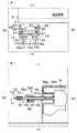
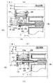
図1乃至図18は本発明に係る便座装置(以下、「本発明便座装置」と言う。)の第1の実施の形態を示すものであって、図1は支持体6に便座2を装着した状態の本発明便座装置1の概略構成を示す平面図、図2は同装着状態の本発明便座装置1の左側面図、図3は図2の一点鎖線イで囲まれた箇所を拡大して示す断面図である。図4は一方の枢支部X1の一方軸受部13及び軸抜け防止手段26を示すものであって、図(A)は左側面図、図(B)は正面図、図(C)は底面図、図(D)は図(A)のd−d線で断面した断面図、図(E)はロック状態の半截した正面図である。図5は一方の枢支部X1の一方枢軸10及び押圧手段40を断面して示すものであって、図(A)は平面図、図(B)は要部を断面した正面図である。図6は一方の枢支部X1の一方軸受部13及び軸抜け防止手段26の別態様を示すものであって、図(A)は左側面図、図(B)は半截した正面図である。図7の図(A)及び図(B)は押圧手段の異なる別態様を断面して示す正面図である。図8は一方の枢支部を示すものであって、図(A)は一方枢軸10と一方軸受部13の分離状態を示す左側面図、図(B)は同分離状態を示す正面図、図(C)は一方軸受部13に一方枢軸10を入れている途中の状態を示す左側面図、図(D)は同状態を示す正面図である。図9は一方の枢支部X1を示すものであって、図(A)は一方軸受部13に一方枢軸10を入れて軸抜け防止手段26が非ロック状態の左側面図、図(B)は同状態を示す正面図、図(C)は一方軸受部13に一方枢軸10を入れて軸抜け防止手段26をロック状態とした左側面図、図(D)は同状態を示す正面図である。
(First embodiment)
1 to 18 show a first embodiment of a toilet seat device according to the present invention (hereinafter referred to as “the toilet seat device of the present invention”). FIG. 1 shows that a toilet seat 2 is attached to a support 6. FIG. 2 is a left side view of the toilet seat device 1 of the present invention in the mounted state, and FIG. 3 is an enlarged view of a portion surrounded by a dashed line in FIG. FIG. 4A and 4B show the one bearing portion 13 and the shaft dropout prevention means 26 of one pivotal support portion X1, wherein FIG. 4A is a left side view, FIG. 4B is a front view, and FIG. (D) is a cross-sectional view taken along the line dd in FIG. (A), and (E) is a half-front view in a locked state. FIG. 5 is a cross-sectional view of the one pivot shaft 10 and the pressing means 40 of one pivot portion X1, wherein FIG. 5 (A) is a plan view and FIG. 6A and 6B show another embodiment of the one bearing portion 13 and the shaft dropout prevention means 26 of the one pivot support portion X1, wherein FIG. 6A is a left side view and FIG. FIG. 7A and FIG. 7B are front views showing in cross section different modes of the pressing means. FIG. 8 shows one pivotal support, where FIG. (A) is a left side view showing a separated state of the one pivot 10 and one bearing 13, and FIG. 8 (B) is a front view showing the separated state. (C) is the left view which shows the state in the middle of putting the one pivot 10 in the one bearing part 13, and figure (D) is a front view which shows the same state. FIG. 9 shows one pivotal support portion X1, FIG. 9A is a left side view in which the pivot shaft 10 is inserted into the one bearing portion 13 and the shaft removal preventing means 26 is unlocked, and FIG. A front view showing the same state, FIG. (C) is a left side view in which the one pivot 10 is inserted into the one bearing portion 13 and the shaft dropout preventing means 26 is locked, and FIG. (D) is a front view showing the same state. .

図10は他方の枢支部X2を示すものであって他方軸受部15と他方枢軸14の接合状態の正面図である。図11は他方の枢支部X2の他方枢軸14を示すものであって、図(A)は部分断面した正面図、図(B)は左側面図、図(C)は別態様の要部を示す正面図である。図12は他方の枢支部X2の他方軸受部15を示すものであって、図(A)は便座接合作業の開始状態の他方枢軸14を二点鎖線で示す正面図、図(B)は右側面図である。図13は他方の枢支部X2の他方軸受部15を示すものであって、図(A)は便座接合作業の完了状態の他方枢軸14を二点鎖線で示す正面図、図(B)は同状態の右側面図である。図14は便座を水平な姿勢(伏倒状態)にして便座接合作業ができるようにした態様の他方の枢支部X2の他方軸受部15を示すものであって、図(A)は便座接合作業の開始状態の他方枢軸14を二点鎖線で示す平面図、図(B)は右側面図である。図15は異物侵入防止具38を備えた態様の他方の枢支部X2を示すものであって他方軸受部15と他方枢軸14の接合状態の正面図である。図16は異物侵入防止具38を備えた態様の他方の枢支部X2の他方枢軸14を示すものであって、図(A)は部分断面した正面図、図(B)は左側面図である。   FIG. 10 is a front view showing the other pivotal support portion X <b> 2, in which the other bearing portion 15 and the other pivot shaft 14 are joined. FIG. 11 shows the other pivot 14 of the other pivot X2, in which FIG. (A) is a partially sectioned front view, FIG. (B) is a left side view, and FIG. FIG. FIG. 12 shows the other bearing portion 15 of the other pivot portion X2. FIG. 12 (A) is a front view showing the other pivot 14 in the start state of the toilet seat joining operation with a two-dot chain line, and FIG. FIG. FIG. 13 shows the other bearing portion 15 of the other pivot support portion X2. FIG. 13 (A) is a front view showing the other pivot shaft 14 in a state where the toilet seat joining operation is completed by a two-dot chain line, and FIG. It is a right view of a state. FIG. 14 shows the other bearing portion 15 of the other pivotal support portion X2 in a mode in which the toilet seat can be joined in a horizontal posture (downward state), and FIG. 14 (A) shows the toilet seat joining operation. A plan view showing the other pivot 14 in the starting state by a two-dot chain line, and FIG. FIG. 15 is a front view showing the other pivotal support portion X <b> 2 having the foreign object intrusion prevention tool 38, and the joined state of the other bearing portion 15 and the other pivot shaft 14. FIG. 16 shows the other pivot shaft 14 of the other pivotal support portion X2 in the aspect provided with the foreign substance intrusion prevention device 38, wherein FIG. 16 (A) is a partially sectional front view, and FIG. 16 (B) is a left side view. .

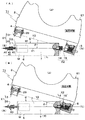
図17及び図18は支持体6に便座2を装着する手順を示す部分断面した正面図であって、図17(A)は支持体6と便座2を完全に分離した状態を示し、図17(B)は便座傾斜姿勢E1のまま他方軸受部15の嵌挿用凹部16へ他方枢軸14を挿入する装着開始状態を示し、図18(A)は一方の枢支部X1の一方枢軸10へ一方軸受部13を接近させた状態を示し、図18(B)は便座2の装着状態を示す。なお、図中に「伏倒状態」と記述されている便座2は、水平な状態に倒れて着座使用可能な状態になっており、図中に「起立状態」と記述されている便座2は、揺動中心側(便座後方側)を下にして揺動先端側(便座前方側)を起こした状態となっている(以下同様)。   17 and 18 are partially sectional front views showing a procedure for mounting the toilet seat 2 on the support body 6. FIG. 17A shows a state in which the support body 6 and the toilet seat 2 are completely separated. FIG. 18B shows a mounting start state in which the other pivot 14 is inserted into the fitting recess 16 of the other bearing portion 15 with the toilet seat tilted posture E1, and FIG. 18A shows one of the pivots X1 toward the one pivot 10. FIG. 18B shows a state in which the toilet seat 2 is mounted. Note that the toilet seat 2 described in the figure as “in a prone state” falls into a horizontal state and is ready for seating, and the toilet seat 2 described in the figure as “standing state” is The swinging center side (toilet seat rear side) faces down and the swinging tip side (toilet seat front side) is raised (the same applies hereinafter).

本発明便座装置1は、図1に示す如く、便器(図示省略)の後方上面に設置される支持体6と、支持体6に揺動自在に支持される便座2と、支持体6に便座2を揺動自在に枢支する左右の一方(本例では「左」を言う。以下同様)の枢支部X1及び左右の他方(本例では「右」を言う。以下同様)の枢支部X2を備え、支持体6に対して便座2が両方の枢支部X1,X2を介して着脱可能になっている。なお、本発明便座装置1は、図1に示す態様のものと左右対称に形成して、一方を「右」とすると共に他方を「左」とすることもある。   As shown in FIG. 1, the toilet seat device 1 of the present invention includes a support body 6 installed on a rear upper surface of a toilet (not shown), a toilet seat 2 supported swingably on the support body 6, and a toilet seat on the support body 6. 2 pivotally supports the left and right (referred to as “left” in this example; the same applies hereinafter) and the other left and right (referred to as “right” in the present example; hereinafter applies) X2 The toilet seat 2 can be attached to and detached from the support body 6 through both pivotal support portions X1 and X2. The toilet seat device 1 according to the present invention is formed symmetrically with the one shown in FIG. 1 so that one is “right” and the other is “left”.

前記便座2は、図1及び図2に示す如く、着座面(着座した使用者の臀部の接触が予定される部分)3aを形成した本体部3と、本体部3の揺動中心側となる後方の両側に突設した一方の取付用腕部4及び他方の取付用腕部5とからなる。便座2は、本体部3の内部に、電気式加熱手段H、温度センサT及び便座側制御部C2が設けられ、便座側制御部C2で加熱手段H及び温度センサTの通電を制御するようにしてある。   As shown in FIGS. 1 and 2, the toilet seat 2 is a main body portion 3 on which a seating surface (a portion where a seated user's buttocks contact is planned) 3 a and a swing center side of the main body portion 3. It consists of one mounting arm 4 and the other mounting arm 5 projecting on both sides of the rear. The toilet seat 2 is provided with an electric heating means H, a temperature sensor T, and a toilet seat side control unit C2 inside the main body 3, and the energization of the heating means H and the temperature sensor T is controlled by the toilet seat side control unit C2. It is.

前記加熱手段Hは、図1〜図3に示す如く、本体部3の着座面3aを形成する表面材3bの裏面側に設けた鉄・銅・アルミニウム等の金属や、これらを主体とする合金又は金属化合物などの導電性材料をシート状の形態とした発熱体17と、発熱体17の下方側で底板3c上に設けた誘導コイル18と、発熱体17と誘導コイル18の間に充填した断熱層19との組み合わせからなり、誘導コイル18で発熱体17に渦電流を生じさせて発熱体17を発熱させて着座面3aを迅速に昇温するようにしてある。加熱手段Hは、誘導加熱による迅速加熱方式に限定するものではなく、面状等の電気ヒータで構成することもある。便座側制御部C2は、温度センサTが出力する温度信号を高周波信号に変換して、図1に示す一方の枢支部X1に設けた信号伝達部20の一次信号コイル21及び二次信号コイル22を介して、後述する支持体側制御部C1へ伝送する機能を有している。   As shown in FIGS. 1 to 3, the heating means H is a metal such as iron, copper, or aluminum provided on the back side of the surface material 3 b that forms the seating surface 3 a of the main body 3, or an alloy mainly composed of these metals. Alternatively, a heating element 17 in the form of a sheet of a conductive material such as a metal compound, an induction coil 18 provided on the bottom plate 3c below the heating element 17, and a space between the heating element 17 and the induction coil 18 are filled. It consists of a combination with the heat insulating layer 19, and an eddy current is generated in the heating element 17 by the induction coil 18 to cause the heating element 17 to generate heat, thereby rapidly raising the temperature of the seating surface 3a. The heating means H is not limited to the rapid heating method by induction heating, and may be constituted by a planar electric heater or the like. The toilet seat side control unit C2 converts the temperature signal output from the temperature sensor T into a high frequency signal, and the primary signal coil 21 and the secondary signal coil 22 of the signal transmission unit 20 provided in one pivotal support portion X1 shown in FIG. And has a function of transmitting to the support side control unit C1 to be described later.

前記支持体6は、図1に示す如く、例えば箱状の形態を有し、前記便座2の両方の取付用腕部4,5で挟まれる膨出部7を前面部に形成してある。前記支持体6は、その内部に、電源Wに接続されて電力の供給を受けると共に前記信号伝達部20の二次信号コイル22を介して温度信号を受ける支持体側制御部C1が設けられている。支持体側制御部C1は、他方の枢支部X2に設けられる給電装置23と、もう一方の枢支部X1に設けられる駆動モータMとに電力を供給する。給電装置23は、他方の枢支部X2に設けて制御部C1に接続した一次コイル24(図7参照)と、他方の枢支部X2に設けて加熱手段Hに接続した二次コイル25(図7参照)とからなり、両コイル間の電磁誘導で給電を行うようにしてある。駆動モータMは、便座2を強制的に揺動させたり、便蓋(図示略)を自動開閉したりするものである。   As shown in FIG. 1, the support 6 has a box shape, for example, and is formed with a bulging portion 7 sandwiched between both attachment arm portions 4 and 5 of the toilet seat 2 on the front surface portion. The support 6 is provided with a support-side control unit C1 that is connected to a power source W and receives power supply, and receives a temperature signal through the secondary signal coil 22 of the signal transmission unit 20. . The support body side control part C1 supplies electric power to the electric power feeder 23 provided in the other pivot part X2, and the drive motor M provided in the other pivot part X1. The power feeding device 23 includes a primary coil 24 (see FIG. 7) provided on the other pivot X2 and connected to the controller C1, and a secondary coil 25 provided on the other pivot X2 and connected to the heating means H (FIG. 7). The power is fed by electromagnetic induction between the two coils. The drive motor M forcibly swings the toilet seat 2 and automatically opens and closes the toilet lid (not shown).

本発明便座装置1は、図1に示す如く、便座2の温度センサTが出力する温度信号を信て伝達部20の一次信号コイル21及び二次信号コイル22による無配線方式で支持体6の制御部C1へ伝送できると共に、支持体6の制御部C1から便座2の加熱手段Hへ給電装置23の一次コイル24及び二次コイル25による無配線方式で給電できるので、支持体6と便座2の間に電気コードを備える必要がなく、電気式加熱手段Hを設けた便座2の分離をコードレスで簡単にできるようになっている。   As shown in FIG. 1, the toilet seat device 1 of the present invention receives a temperature signal output from the temperature sensor T of the toilet seat 2 and transmits the support 6 in a non-wiring manner using the primary signal coil 21 and the secondary signal coil 22 of the transmission unit 20. In addition to being able to transmit to the control unit C1, power can be supplied from the control unit C1 of the support 6 to the heating means H of the toilet seat 2 in a non-wired manner by the primary coil 24 and the secondary coil 25 of the power supply device 23. There is no need to provide an electric cord between the two, and the toilet seat 2 provided with the electric heating means H can be easily separated cordlessly.

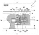
前記一方(左)の枢支部X1は、図1、図8及び図9に示す如く、前記モータMの出力軸であって支持体6の膨出部7の一方側面7cから更に一方の方向(左方向)へ向かって突出する一方枢軸10と、一方の取付用腕部4に設けられ、軸装部13a及び軸装部13aへ一方枢軸10を出し入れするための一方枢軸出入用開口部13bを有する一方軸受部13と、一方枢軸出入用開口部13bを通過させて一方枢軸10を入れた軸装部13aを一方枢軸10の突出先端側(左側)へ向かって押圧する押圧手段40と、軸装部13aへ挿着した一方枢軸10が抜け出すのを防止するための軸抜け防止手段26とを備えている。なお、一方の枢支部X1は、前記信号伝達部20の一次信号コイル21(図1参照)を一方軸受部13に備えると共に、二次信号コイル22を一方枢軸10側となる膨出部7の一方側面近傍に備えている。   The one (left) pivot portion X1 is an output shaft of the motor M and is further in one direction (from one side surface 7c of the bulging portion 7 of the support body 6 as shown in FIGS. One pivot 10 projecting toward the left) and one pivot arm opening / closing opening 13b provided on one mounting arm 4 for inserting / removing the pivot 10 to / from the shaft mount 13a. The one bearing portion 13, the pressing means 40 that presses the shaft mounting portion 13 a through which the one pivot 10 is inserted through the one pivot opening / closing opening 13 b toward the protruding tip side (left side) of the one pivot 10, and the shaft A shaft drop prevention means 26 for preventing the one pivot 10 inserted into the mounting portion 13a from coming out is provided. One pivot portion X1 includes the primary signal coil 21 (see FIG. 1) of the signal transmission portion 20 in the one bearing portion 13 and the secondary signal coil 22 of the bulging portion 7 on the one pivot 10 side. On the other hand, it is provided near the side surface.

前記一方枢軸10は、図5及び図8(B)に示す如く、膨出部7に取付け固定された前記モータMの出力軸であって、同芯二軸の便座駆動用軸11と便蓋駆動用軸12からなり、便蓋駆動用軸12が便座駆動用軸11を貫通して突出している。   As shown in FIGS. 5 and 8B, the one pivot 10 is an output shaft of the motor M attached and fixed to the bulging portion 7, and is a concentric biaxial toilet seat drive shaft 11 and a toilet lid. The toilet lid driving shaft 12 includes a driving shaft 12 and projects through the toilet seat driving shaft 11.

前記押圧手段40は、図5及び図8(B)に示す如く、便座・便蓋揺動用モータMの回転出力軸で形成した一方枢軸10の便座駆動用軸11にセットネジ45等で固着され、起立状態の便座2が便座接合姿勢F(図9(A)〜(D)、図18(B)参照)のときに一方軸受部13の軸装部13aへ入ってモータ回転出力を軸装部13aへ伝達する伝動具42と、一方枢軸10の便座駆動用軸11に摺動自在に外嵌され、便座2が便座接合姿勢Fのときに軸装部13aへ入る移動具43と、便座駆動用軸11を外嵌するようにして伝動具42と移動具43の間に配置された圧縮コイルバネからなるバネ44とを備え、便座2が便座接合姿勢Fのときに、伝動具42、移動具43及びバネ44が一体となって、一方軸受部13の軸装部13aの内側空間へ入って、バネ力で移動具43を介して軸装部13aを一方枢軸10の先端側(左側)へ向かって押圧するようにしてある。移動具43は、便座駆動用軸11と一体に回転するように、便座駆動用軸11に固着された伝動具42にバネ44を介して連結されるか、または、便座駆動用軸11の横断面の外形を多角形(例えば、四角形)にして便座駆動用軸11の回りを回転しないように外嵌される。   As shown in FIGS. 5 and 8B, the pressing means 40 is fixed to the toilet seat drive shaft 11 of the pivot 10 formed by the rotation output shaft of the toilet seat / toilet lid swinging motor M with a set screw 45 or the like. When the toilet seat 2 in the upright state is in the toilet seat joint posture F (see FIGS. 9A to 9D and FIG. 18B), it enters the shaft mounting portion 13a of the one bearing portion 13 and shafts the motor rotation output. A transmission tool 42 that transmits to the portion 13a, a movable tool 43 that is slidably fitted to the toilet seat drive shaft 11 of the one pivot 10, and enters the shaft mounting portion 13a when the toilet seat 2 is in the toilet seat joint posture F; A spring 44 made of a compression coil spring disposed between the transmission tool 42 and the moving tool 43 so as to fit the drive shaft 11 is provided. When the toilet seat 2 is in the toilet seat joint posture F, the transmission tool 42 is moved. The tool 43 and the spring 44 are integrated, and one of the shaft mounting portions 13a of the one bearing portion 13 Enter into the space, it is to be pressed toward the distal end side of JikuSobu 13a the other hand pivot 10 via a moving fixture 43 by the spring force (left side). The moving tool 43 is connected to a transmission tool 42 fixed to the toilet seat driving shaft 11 via a spring 44 so as to rotate integrally with the toilet seat driving shaft 11, or crossing the toilet seat driving shaft 11. The outer shape of the surface is a polygon (for example, a quadrangle), and is fitted so as not to rotate around the toilet seat drive shaft 11.

前記押圧手段40は、図5に示す如く、モータMが便座を起立状態とする回転位置で停止している状態のとき、移動具43の一方側(左側)の外面43aが、上方から下方へ向かう程に一方側(左側)へ移行する傾斜面に形成されている。また、押圧手段40と対となる一方軸受部13の軸装部13aは、図4に示す如く、一方枢軸出入用開口部13bを除く部分が四周の周壁13c,13d,13e,13fで囲まれて形成され、一方側(左側)の周壁13cの内面13c−1が、便座2の起立状態で上方から下方へ向かう程に一方側(左側)へ移行する傾斜面に形成されている。押圧手段40及び一方軸受部13は、このように移動具43の外面43a及び軸装部13aの内面13c−1の各々を傾斜面とすることで、図18に示すように便座2が便座傾斜姿勢E2から便座接合姿勢Fへ移行するときに、伝動具42、移動具43及びバネ44からなる押圧手段40が軸装部13aの内側空間へ入り易くなっている。   As shown in FIG. 5, when the motor M is stopped at the rotational position where the toilet seat is raised, the outer surface 43a on one side (left side) of the moving tool 43 is moved downward from above. It is formed in the inclined surface which transfers to one side (left side), so that it goes. Further, as shown in FIG. 4, the shaft mounting portion 13a of the one bearing portion 13 that is paired with the pressing means 40 is surrounded by four peripheral walls 13c, 13d, 13e, and 13f, except for the one pivot opening / closing opening 13b. The inner surface 13c-1 of the peripheral wall 13c on one side (left side) is formed as an inclined surface that shifts to one side (left side) from the upper side to the lower side in the standing state of the toilet seat 2. As shown in FIG. 18, the pressing means 40 and the one-side bearing portion 13 incline the toilet seat 2 as shown in FIG. 18 by making each of the outer surface 43a of the moving tool 43 and the inner surface 13c-1 of the shaft mounting portion 13a as inclined surfaces. When shifting from the posture E2 to the toilet seat joining posture F, the pressing means 40 including the transmission tool 42, the moving tool 43, and the spring 44 is easy to enter the inner space of the shaft mounting portion 13a.

前記押圧手段40は、図5に示すようにバネ44を圧縮コイルバネで形成する以外に、図7(A)に示すように板バネで形成することもある。また、押圧手段40は、便座駆動用軸11に移動具43を摺動自在に外嵌させるために、図5に示すように移動具43に挿通孔43bを設ける以外に、図7(B)に示すように逆U字状の挿通溝43cを設けることもある。   The pressing means 40 may be formed by a leaf spring as shown in FIG. 7A, in addition to the spring 44 being formed by a compression coil spring as shown in FIG. Further, the pressing means 40 is provided with an insertion hole 43b as shown in FIG. 5 in order to slidably fit the moving tool 43 on the toilet seat drive shaft 11, as shown in FIG. In some cases, an inverted U-shaped insertion groove 43c may be provided.

前記押圧手段40は、図5に示す如く、便座揺動用モータMの回転出力軸で形成した一方枢軸10に固着された伝動具42と、一方枢軸10に摺動自在に外嵌された移動具43と、伝動具42と移動具43の間に配置されたバネ44とからなるため、一方の枢支部X1に便座揺動用モータMの回転出力を便座2へ伝達する機構を簡単に組み込むことができる。   As shown in FIG. 5, the pressing means 40 includes a transmission tool 42 fixed to the one pivot 10 formed by the rotation output shaft of the toilet seat swinging motor M, and a moving tool slidably fitted to the one pivot 10. 43 and a spring 44 disposed between the transmission tool 42 and the moving tool 43, a mechanism for transmitting the rotational output of the toilet seat swinging motor M to the toilet seat 2 can be easily incorporated into one pivotal support portion X1. it can.

前記便座駆動用軸11は、図9(C)(D)に示す如く、押圧手段40の駆動力伝達用の伝動具42が、一方軸受部13の軸装部13aに入って周壁13e,13f(図4参照)に係合することで、駆動モータMの便座駆動用出力を伝動具42、一方軸受部13及び一方の取付用腕部4を介して便座本体3へ伝達して、便座2を電動式で強制的に仰伏揺動させるようになっている。前記便蓋駆動用軸12は、図示は省略したが、便蓋の軸受部が着脱自在に外嵌装着され、駆動モータMの便蓋駆動用出力を軸受部を介して便蓋へ伝達して、便蓋を電動式で強制的に仰伏揺動させるようになっている。   As shown in FIGS. 9C and 9D, the toilet seat drive shaft 11 includes a transmission member 42 for transmitting the driving force of the pressing means 40 and enters the shaft mounting portion 13a of the one bearing portion 13 so that the peripheral walls 13e and 13f. (See FIG. 4), the toilet seat drive output of the drive motor M is transmitted to the toilet seat body 3 via the transmission device 42, the one bearing portion 13 and the one mounting arm portion 4. Is forcibly oscillated on and off. Although not shown, the toilet lid driving shaft 12 is detachably fitted with a bearing portion of the toilet lid, and transmits the toilet lid driving output of the drive motor M to the toilet lid via the bearing portion. The toilet lid is forcibly turned on and off by electric.

前記軸抜け防止手段26は、図4に示す如く、一方の取付用腕部4に移動自在に設けたロック具28を、一方の枢支部X1の軸装部13aから一方枢軸10が出ることを防止しない待機位置K(図9(A)参照)から防止するロック位置L(図9(B)参照)まで移動させるものであり、本例では、一方の取付用腕部4にロック具28を揺動自在に枢支27してある。ロック具28は、左右の揺動片30,30を枢支27側の連結軸31及び揺動先端側の操作棒32で連結して一体とし、各揺動片30に嵌合用凹部33を切込み形成し、待機位置Kからロック位置Lへ前進させたとき、図9(C)(D)に示すように、一方軸受部13の軸装部13aへ挿着している一方枢軸10を嵌合用凹部33,33で外嵌して、一方軸受部13と一方枢軸10との分離を防止するようにしてある。上記操作棒32は、ロック具28を揺動させるときに、指先で摘んで操作できるようになっている。ロック具28は、左右の各嵌合用凹部33に係止用突起33a,33aを設けて、嵌合用凹部33,33が外嵌した一方枢軸10(図9(C)(D)参照)を係止用突起33a,33aで無理バメ状態にして抜け難くしてある。   As shown in FIG. 4, the shaft slip-off preventing means 26 is provided with a lock tool 28 movably provided on one mounting arm portion 4 so that the one pivot 10 comes out from the shaft mounting portion 13a of one pivot support portion X1. It is moved from a standby position K (see FIG. 9 (A)) that is not prevented to a locked position L (see FIG. 9 (B)) that is prevented. A pivot 27 is swingably supported. The locking device 28 is formed by connecting the left and right swinging pieces 30, 30 with a connecting shaft 31 on the pivot 27 side and an operating rod 32 on the swinging tip side, and cutting a fitting recess 33 into each swinging piece 30. When formed and advanced from the standby position K to the lock position L, as shown in FIGS. 9C and 9D, the one pivot 10 inserted into the shaft mounting portion 13a of the one bearing portion 13 is used for fitting. The recesses 33 and 33 are externally fitted to prevent the one bearing portion 13 and the one pivot 10 from being separated. The operating bar 32 can be operated by picking it with a fingertip when the locking device 28 is swung. The locking device 28 is provided with locking projections 33a and 33a in the left and right fitting recesses 33, and engages the one pivot 10 (see FIGS. 9C and 9D) on which the fitting recesses 33 and 33 are fitted. The stop projections 33a and 33a are forced into a swallowed state and are not easily removed.

なお、前記軸抜け防止手段26は、図6(A)(B)に示す如く、一方の取付用腕部4とロック具28の間に、ロック具28を矢符P方向へ付勢するロック用付勢具35を設け、ロック具28について待機位置Kで手を離すとロック用付勢具35に貯えられている反発力でロック位置Lへ自動的に移動させて、ロック具28のロック状態を確実なものとするように構成することもある。ロック用付勢具35は、例えば連結軸31に外嵌したつる巻バネを用い、連結軸31の中間に固着した鍔部36と取付用腕部4との間に配置して、鍔部36及び取付用腕部4につる巻バネの端部を連結してある。ロック具28は、ロック用付勢具35を設けるとき、各嵌合用凹部33の係止用突起33a,33a(図4(A)参照)を省略することができる。   As shown in FIGS. 6A and 6B, the shaft slip-off preventing means 26 is a lock that urges the lock tool 28 in the direction of the arrow P between one mounting arm 4 and the lock tool 28. When the locking device 28 is released at the standby position K, the locking device 28 is automatically moved to the locking position L by the repulsive force stored in the locking device 35 to lock the locking device 28. It may be configured to ensure the state. The locking urging tool 35 is, for example, a helical spring that is externally fitted to the connecting shaft 31 and is disposed between the flange portion 36 fixed to the middle of the connecting shaft 31 and the mounting arm portion 4. And the edge part of the coiled spring is connected with the arm part 4 for attachment. When the locking device 28 is provided with the locking urging device 35, the locking projections 33a and 33a (see FIG. 4A) of the respective fitting recesses 33 can be omitted.

前記一方側(左側)の取付用腕部4及び軸抜け防止手段26は、図18(A)、図8(A)〜(D)及び図9(A)(B)に示すように、ロック具28を待機位置Kに位置させたまま分離状態の便座2を支持体6に装着できるようにするために、他方(右)の枢支部X2の後述する他方枢軸14に他方軸受部15に挿入して便座2を装着方向へ揺動させたとき、支持体6の膨出部7の隅部7a等にロック具28を衝突させないように便座本体部3に設けられている。   As shown in FIGS. 18A, 8A to 8D, and FIGS. 9A and 9B, the one side (left side) mounting arm 4 and the shaft slip-off preventing means 26 are locked. In order to allow the toilet seat 2 in the separated state to be mounted on the support body 6 while the tool 28 is positioned at the standby position K, the other bearing portion 15 is inserted into the other pivot 14 described later of the other (right) pivot X2. Thus, when the toilet seat 2 is swung in the mounting direction, the toilet seat body 3 is provided so that the lock tool 28 does not collide with the corner portion 7a of the bulging portion 7 of the support 6 or the like.

前記他方(右)の枢支部X2は、図10乃至図13に示す如く、他方の取付用腕部5から一方の方向(左方向)へ向かって突出する短円柱状の他方枢軸14と、支持体6の膨出部7の他方側に開設した横向きの嵌挿用凹部16へ開口端16bから他方枢軸14を出し入れできる他方軸受部15とからなる。他方軸受部15は、便座2の装着手順を説明する図17に示す如く、支持体6の一方枢軸10及び他方軸受部15が形成する支持体軸芯Y1(便座2を揺動自在に枢支するときの支持体側の枢支中心となるもの)と分離状態の便座2の一方軸受部13及び他方枢軸14が形成する便座軸芯Y2(便座2を揺動自在に枢支するときの便座側の枢支中心となるもの)との交差角θを大きくした便座傾斜姿勢E1のまま他方枢軸14を受け入れでき、更に、同手順を説明する図18に示す如く、他方枢軸14を受け入れたまま両軸芯Y1,Y2の交差角θを小さくさせる便座傾斜姿勢E2(図18(A)参照)を経て両軸芯Y1,Y2を合致させる便座接合姿勢F(図18(B)参照)へ移行させるのに伴い、前記一方(左)の枢支部X1の一方枢軸10が、図8(C)(D)に示す如く一方軸受部13の開口部13bを通過して軸装部13aへ挿着できるように、図12に示すように嵌挿用凹部16の奥側16aに比べて開口端16b側を大径となるように傾斜部16cを形成してある。嵌挿用凹部16は、この開口端16b側を大径にする傾斜部16cが設けられる領域を、便座傾斜姿勢E1の他方枢軸14を受け入れるときの便座軸芯Y2が通過する他方枢軸受入れ側とすることで、他方枢軸受入れ側以外の大径でない領域を設けて異物が嵌挿用凹部内へ侵入するのを抑制するようにしてある。嵌挿用凹部16は、この大径となる他方枢軸受入れ側を嵌挿用凹部16の下半側に位置させてあり、大径の他方枢軸受入れ側を便座使用者から見え難くして見栄えよくなるようにしてある。   The other (right) pivot X2, as shown in FIGS. 10 to 13, is supported by a short columnar other pivot 14 projecting from the other mounting arm 5 in one direction (left direction). It comprises the other bearing portion 15 in which the other pivot 14 can be taken in and out from the opening end 16b into a laterally fitting recess 16 which is opened on the other side of the bulging portion 7 of the body 6. As shown in FIG. 17 for explaining the mounting procedure of the toilet seat 2, the other bearing portion 15 is pivotally supported so that the pivot shaft 10 of the support 6 and the support shaft core Y1 formed by the other bearing portion 15 (the toilet seat 2 can swing freely). The toilet seat core Y2 formed by the one bearing portion 13 and the other pivot 14 of the toilet seat 2 in a separated state and the pivot seat side when the toilet seat 2 is pivotably supported. The other pivot 14 can be received in the toilet seat tilted posture E1 with a larger crossing angle θ with the center of the pivot support), and the both pivots 14 can be received while the other pivot 14 is received as shown in FIG. After passing through the toilet seat tilting posture E2 (see FIG. 18A) for reducing the crossing angle θ between the shaft cores Y1 and Y2, a transition is made to the toilet seat joining posture F (see FIG. 18B) for matching both shaft cores Y1 and Y2. As a result, the one pivot of the one (left) pivot X1 As shown in FIG. 12, the back of the recessed portion 16 for insertion can be inserted into the shaft mounting portion 13a through the opening 13b of the one bearing portion 13 as shown in FIGS. The inclined portion 16c is formed so that the opening end 16b side has a larger diameter than the side 16a. The recessed portion 16 for insertion is provided on the other pivot bearing insertion side through which the toilet seat axis Y2 passes when receiving the other pivot 14 of the toilet seat tilt posture E1 in the region where the inclined portion 16c having a large diameter on the opening end 16b side is provided. By doing so, a non-large-diameter region other than the other pivot bearing insertion side is provided to prevent foreign matter from entering the insertion recess. The recess 16 for insertion is positioned on the lower half side of the other pivot bearing 16 having the large diameter on the lower half side of the recess 16 for insertion. It is like that.

前記他方軸受部15は、図12に示す如く、嵌挿用凹部16の奥側突き当たりに、前記両軸芯Y1,Y2を大きく交差させる便座傾斜姿勢E1(図17(B)参照)のまま他方枢軸14を受け入れるときに他方枢軸14の一方側外隅部14aを侵入させる侵入用空間部16dと、前記両軸芯Y1,Y2を小さく交差させる便座傾斜姿勢E2(図18(A)参照)を経て両軸芯Y1,Y2を合致させる便座接合姿勢F(図18(B)及び図13参照)へ移行させるのに伴い傾動する他方枢軸14の先端面14bを当接させて一方側外隅部14aを侵入用空間部16dから引き出させる当接面16eとを設けてある。侵入用空間部16d及び当接面16eは、図18(A)に示す如く、便座2が両軸芯Y1,Y2を小さく交差させる便座傾斜姿勢E2で傾動するとき、一方(左)の枢支部X1の一方軸受部13が支持体6の膨出部7の一方側の外隅部7aの外側を通過し始めた後に、当接面16e(図12参照)に対する他方枢軸14の先端面14bの当接を開始させ、一方側の外隅部7aの外側を通過するまでは便座2を他方(右)へ移動させないようにしてある。本例の他方軸受部15は、図12に示す如く、便座2を起立させた状態で着脱操作を行うようにするために(図17及び図18参照)、侵入用空間部16dを下方に設けると共に、当接面16eを上方に設けてある。他方軸受部15は、嵌挿用凹部16の奥側突当りに、侵入用空間部16dから当接面16eへ向かって連続的に傾斜する奥側突き当たり面16gを形成することにより、他方枢軸14の先端面14bを傾斜させつつ侵入用空間部16dから当接面16eへ円滑に引き出させるようにしてある。また、奥側突き当たり面16gは、侵入用空間部16dへ侵入したコイン等の異物が嵌挿用凹部16に密着して外れ難くなるのを防止する役割もある。   As shown in FIG. 12, the other bearing portion 15 has the toilet seat tilted posture E1 (see FIG. 17B) that makes the two shaft cores Y1 and Y2 substantially intersect at the back end of the recessed portion 16 for insertion. An intrusion space portion 16d that allows one side outer corner portion 14a of the other pivot shaft 14 to enter when the pivot shaft 14 is received, and a toilet seat inclination posture E2 (see FIG. 18A) that slightly intersects the two shaft cores Y1 and Y2. Then, the tip end surface 14b of the other pivot shaft 14 which is tilted as it is shifted to the toilet seat joint posture F (see FIGS. 18B and 13) for matching both the shaft cores Y1 and Y2 is brought into contact with the one outer corner portion. A contact surface 16e for pulling out 14a from the intrusion space 16d is provided. As shown in FIG. 18A, when the toilet seat 2 tilts in the toilet seat tilting posture E2 that slightly intersects the two shaft cores Y1 and Y2, as shown in FIG. After the one bearing portion 13 of X1 starts to pass the outside of the outer corner portion 7a on one side of the bulging portion 7 of the support 6, the tip surface 14b of the other pivot 14 with respect to the contact surface 16e (see FIG. 12). The abutment is started and the toilet seat 2 is not moved to the other (right) until it passes the outside of the outer corner 7a on one side. As shown in FIG. 12, the other bearing portion 15 of this example is provided with an intrusion space portion 16d below in order to perform the detaching operation with the toilet seat 2 raised (see FIGS. 17 and 18). In addition, the contact surface 16e is provided on the upper side. The other bearing portion 15 is formed with a rear end surface 16g that continuously inclines from the intrusion space portion 16d toward the contact surface 16e at the rear end of the fitting insertion recess 16, thereby allowing the other pivot 14 to move. The front end surface 14b is inclined and smoothly drawn from the entry space 16d to the contact surface 16e. Further, the rear side abutting surface 16g also serves to prevent foreign matter such as coins that have entered the intrusion space 16d from coming into close contact with the insertion recess 16 and being difficult to come off.

更に、前記他方軸受部15は、図13に示す如く、嵌挿用凹部16の傾斜部16cと侵入用空間部16dとの間に、軸受面16fを支持体軸芯Y1と平行に形成してある。軸受面16fは、正面側からみて半円状に形成され(図(B)参照)、他方枢軸14の下半外周面を軸支して便座2の荷重を受けるようにしてある(図15参照)。このように構成された他方軸受部15は、便座接合姿勢F(図18(B)参照)のときに、他方枢軸14が一方枢軸側(左側)へ向かって移動するのを当接面16eで阻止しつつ軸受面16fで回転自在に枢支できる。前記他方枢軸14は、便座2が前記押圧手段40の押圧力で一方側(左側)へ押されるのに伴い、先端面14bを他方軸受部15の当接面16eに圧接しつつ回転するとき、円滑な回転が得られるように、図11(C)に示す如く、先端面14bを滑りが良好な滑り部材14cで形成するとよい。   Further, as shown in FIG. 13, the other bearing portion 15 has a bearing surface 16f formed in parallel with the support axis Y1 between the inclined portion 16c of the recess 16 for insertion and the space portion 16d for intrusion. is there. The bearing surface 16f is formed in a semicircular shape when viewed from the front side (see FIG. (B)), and supports the lower half outer peripheral surface of the other pivot 14 to receive the load of the toilet seat 2 (see FIG. 15). ). The other bearing portion 15 configured as described above has the contact surface 16e that the other pivot 14 moves toward the one pivot side (left side) in the toilet seat joining posture F (see FIG. 18B). It can be pivotally supported by the bearing surface 16f while blocking. When the toilet pivot 2 rotates while pressing the front end surface 14b against the contact surface 16e of the other bearing portion 15 as the toilet seat 2 is pressed to one side (left side) by the pressing force of the pressing means 40, As shown in FIG. 11C, the front end surface 14b may be formed of a sliding member 14c having good sliding so that smooth rotation can be obtained.

前記他方(右)の枢支部X2は、図10に示す如く、他方軸受部15を形成する嵌挿用凹部16の奥側の当接面16eと他方枢軸14の先端面14bとで便座移動規制部39が形成され、当接面16eに先端面14bを当接させる位置(便座2の一方側へ向かう移動が規制される規制位置Q)まで、装着する便座2を一方側(左側)へ向かって移動できるようにしてある。   As shown in FIG. 10, the other (right) pivotal support portion X <b> 2 is configured to restrict toilet seat movement by a contact surface 16 e on the inner side of the recess 16 for insertion that forms the other bearing portion 15 and a distal end surface 14 b of the other pivot shaft 14. A portion 39 is formed, and the toilet seat 2 to be mounted is directed to one side (left side) until a position where the tip surface 14b contacts the contact surface 16e (a restriction position Q where movement toward the one side of the toilet seat 2 is restricted). Can be moved.

本発明便座装置1は、図12及び図13に示す如く、他方軸受部15に侵入用空間部16d及び当接面16eを設けることにより、前記両軸芯Y1,Y2を小さく交差させる便座傾斜姿勢E2(図18(A)参照)を経て両軸芯Y1,Y2を合致させる便座接合姿勢F(図18(B)参照)へ移行させるのに伴い傾動する他方枢軸14の一方側外隅部14aを侵入用空間部16dから引き出させて他方枢軸14の先端面14bを当接面16eに乗り上がるように当接させることで、引き出させた寸法分だけ便座軸芯方向Y2に沿う移動を減少させて、装着状態の便座2の便座軸芯方向Y2に沿うガタ付きを小さくすることができる。なお、便座2の便座軸芯方向Y2に沿うガタ付きを押圧手段40で抑制することができるため、他方軸受部15は、図示は省略したが、侵入用空間部16d及び当接面16eを設けることなく、嵌挿用凹部16の奥側突き当たり面の全体を平坦に仕上げた当接面に仕上げて、この当接面に他方枢軸14の先端面14bを当接させて当接面積を大きくすることも可能である。   As shown in FIGS. 12 and 13, the toilet seat device 1 according to the present invention has a toilet seat tilting posture in which both the shaft cores Y1 and Y2 are slightly crossed by providing an intrusion space portion 16d and a contact surface 16e in the other bearing portion 15. One side outer corner portion 14a of the other pivot shaft 14 tilted with the transition to the toilet seat joint posture F (see FIG. 18B) that matches the two shaft cores Y1 and Y2 through E2 (see FIG. 18A). Is pulled out from the intrusion space 16d and the tip surface 14b of the other pivot 14 is brought into contact with the contact surface 16e, thereby reducing the movement along the toilet seat axial direction Y2 by the amount of the drawn-out dimension. Thus, the backlash along the toilet seat axial direction Y2 of the toilet seat 2 in the mounted state can be reduced. In addition, since the backlash along the toilet seat axial direction Y2 of the toilet seat 2 can be suppressed by the pressing means 40, the other bearing portion 15 is omitted from the illustration, but is provided with an intrusion space portion 16d and a contact surface 16e. Instead, the entire abutting surface of the recess 16 for insertion is finished to a flat abutting surface, and the abutting surface is increased by abutting the tip surface 14b of the other pivot 14 with the abutting surface. It is also possible.

本発明便座装置1は、図1乃至図13に示す態様では便座2を起立させた状態で便座接合作業を行うようにしたものであるが、図14に示す如く、便座2を水平な姿勢にして便座接合作業ができるように、他方の枢支部X2の他方軸受部15を形成することも可能である。   The toilet seat device 1 according to the present invention is configured to perform the toilet seat joining operation in a state where the toilet seat 2 is erected in the mode shown in FIGS. 1 to 13, but the toilet seat 2 is set in a horizontal posture as shown in FIG. It is also possible to form the other bearing portion 15 of the other pivotal support portion X2 so that the toilet seat can be joined.

本発明便座装置1は、嵌挿用凹部16への異物の侵入防止を完全なものとするために、図15及び図16に示す如く、他方軸受部15と他方の取付用腕部5との間に異物侵入防止具38を設け、嵌挿用凹部16と他方枢軸14の隙間を異物侵入防止具38で覆うこともある。異物侵入防止具38は、硬質の合成樹脂やゴム素材からなる当接表面が滑り易い閉塞板38aと、軟質の合成樹脂やゴム素材又はバネ材からなる圧縮変形可能な弾性を有する環状の押圧部38bとを備え、図16に示すように他方枢軸14に押圧部38bを外嵌装着させると共に、他方枢軸14に閉塞板38aを遊嵌合させてある。異物侵入防止具38は、図17(B)に示すように支持体軸芯Y1と便座軸芯Y2を大きく交差させた便座傾斜姿勢E1のまま他方枢軸14を他方軸受部15の嵌挿用凹部16の奥側へ挿入するとき、この挿入を阻害しないように環状の押圧部38bの一部が圧縮変形し、また、図15に示すように支持体軸芯Y1と便座軸芯Y2を一致させるように便座2の装着状態を終了して便座2を揺動できる状態となったとき、嵌挿用凹部16の開口端16bの開口周縁に閉塞板38aの当接表面を押圧部38bの弾性押圧力で圧着させて、開口端16bを覆うようになる。異物侵入防止具38は、閉塞板38aの当接表面が滑り易くなっているため、便座2の揺動に伴い、嵌挿用凹部16の開口端16bの開口周縁に対して円滑に摺動して開口端16bを常に覆うことができる。   As shown in FIGS. 15 and 16, the toilet seat device 1 according to the present invention is provided between the other bearing portion 15 and the other mounting arm portion 5 in order to completely prevent foreign matter from entering the fitting insertion recess portion 16. A foreign matter intrusion prevention tool 38 may be provided between them, and the gap between the insertion recess 16 and the other pivot 14 may be covered with the foreign matter intrusion prevention device 38. The foreign matter intrusion prevention tool 38 includes a closing plate 38a having a slippery contact surface made of a hard synthetic resin or a rubber material, and an annular pressing portion having a compressible and deformable elasticity made of a soft synthetic resin, a rubber material, or a spring material. As shown in FIG. 16, the pressing portion 38 b is externally fitted to the other pivot 14, and the closing plate 38 a is loosely fitted to the other pivot 14. As shown in FIG. 17 (B), the foreign matter intrusion prevention tool 38 is a recess for inserting the other pivot shaft 14 into the other bearing portion 15 while maintaining the toilet seat tilting posture E1 in which the support body axis Y1 and the toilet seat axis Y2 are largely intersected. When inserting into the back side of 16, a part of the annular pressing portion 38b is compressed and deformed so as not to inhibit this insertion, and the support body axis Y1 and the toilet seat axis Y2 are made to coincide as shown in FIG. As described above, when the toilet seat 2 is finished mounted and the toilet seat 2 can be swung, the contact surface of the closing plate 38a is placed on the peripheral edge of the opening end 16b of the recess 16 for insertion and elastically pressed by the pressing portion 38b. The opening end 16b is covered by pressure bonding. Since the contact surface of the blocking plate 38a is easy to slip, the foreign substance intrusion prevention device 38 slides smoothly with respect to the opening periphery of the opening end 16b of the recess 16 for insertion as the toilet seat 2 swings. Thus, the open end 16b can always be covered.

前記他方(右)の枢支部X2は、図10に示す如く、他方軸受部15の嵌挿用凹部16より奥側に給電装置23の一次コイル24を埋設すると共に、他方枢軸14に給電装置23の二次コイル25を埋設してある。一次コイル24は、ボビン24aの内部にコイル24bを内蔵させたものであり、また、二次コイル25は、ボビン25aの内部にコイル25bを内蔵させたものである。本発明便座装置1は、便座2の便座軸芯方向Y2に沿うガタ付きを押圧手段40で抑制することができるため、給電装置23の一次コイル24と二次コイル25の間の距離を一定に維持して安定した給電を確保できる。   As shown in FIG. 10, the other (right) pivot support portion X <b> 2 embeds a primary coil 24 of the power feeding device 23 on the back side of the fitting recess 16 of the other bearing portion 15, and the power feeding device 23 on the other pivot 14. The secondary coil 25 is embedded. The primary coil 24 has a coil 24b built in a bobbin 24a, and the secondary coil 25 has a coil 25b built in a bobbin 25a. The toilet seat device 1 according to the present invention can suppress the backlash along the toilet seat axial direction Y2 of the toilet seat 2 by the pressing means 40, so that the distance between the primary coil 24 and the secondary coil 25 of the power feeding device 23 is constant. Maintaining stable power supply can be ensured.

本発明便座装置1は、図示は省略したが、他方の枢支部X2側に備えた給電装置23の外回りに、一次コイル側シール具及び二次コイル側シール具からなる磁気シール具を設け、一次コイル24と二次コイル25の間の電磁誘導による低周波の磁界が給電装置23の外側へ漏れ出るのを抑制するように構成することもある。なお、給電装置23は、磁気シール具が設けられることで、磁界の漏れ出しを抑制すると共に、一次コイル24と二次コイル25の間の伝送効率を上昇させることができるようになる。   Although the illustration of the toilet seat device 1 of the present invention is omitted, a magnetic seal device including a primary coil side seal device and a secondary coil side seal device is provided on the outer periphery of the power supply device 23 provided on the other pivotal support X2 side. The low frequency magnetic field due to electromagnetic induction between the coil 24 and the secondary coil 25 may be configured to suppress leakage to the outside of the power feeding device 23. The power feeding device 23 is provided with the magnetic seal tool, thereby suppressing the leakage of the magnetic field and increasing the transmission efficiency between the primary coil 24 and the secondary coil 25.

本発明便座装置1は、便器(図示略)に固定されている支持体6に分離状態の便器2を手作業で装着するとき、図17(B)に示すように支持体軸芯Y1と便座軸芯Y2を大きく交差させた便座傾斜姿勢E1のまま他方側(右側)の他方枢軸14を他方軸受部15の嵌挿用凹部16の奥側へ挿入した後に、図18(A)(B)に示すように両軸芯Y1,Y2を小さく交差させる便座傾斜姿勢E2を経て両軸芯Y1,Y2を合致させる便座接合姿勢Fへ移行させることで、一方側(左側)の一方枢軸10及び押圧手段40が、移動する一方軸受部13の開口部13bを通過して軸装部13aへ入って便座装着ができる。   The toilet seat device 1 according to the present invention has a support shaft core Y1 and a toilet seat as shown in FIG. 17B when the separated toilet 2 is manually attached to a support 6 fixed to a toilet (not shown). 18A and 18B, after the other pivot shaft 14 on the other side (right side) is inserted into the back side of the recess 16 for insertion of the other bearing portion 15 with the toilet seat tilted posture E1 substantially intersecting the axis Y2. As shown in FIG. 4, the toilet seat tilt posture E2 that slightly intersects the two shaft cores Y1 and Y2 is shifted to the toilet seat joint posture F that matches the two shaft cores Y1 and Y2. The means 40 can pass through the opening 13b of the one bearing portion 13 that moves and enter the shaft mounting portion 13a to attach the toilet seat.

傾動する便座2の軸装部13aの内側空間へ一方枢軸10を入れようとするとき、図8(C)(D)及び図9(A)(B)に示すように、押圧手段40は、一方枢軸10側に設けらている移動具43の傾斜した外面43aに軸装部13aの内面13c−1が当接し、バネ44に反発力を貯えさせつつ移動具43が移動する。次に、便座2が便座接合姿勢F(図18(B)参照)となったときに、便座2を持って装着操作している操作者が便座2から手を離すと、押圧手段40は、バネ44の反発力で移動具43を移動させて軸装部13aを一方枢軸10の突出先端側(左側)へ向かって押圧して、他方(右)の枢支部X2の他方枢軸14を、一方側(左側)へ向かって移動するのが規制される位置(図10及び図18(B)に示すように、他方枢軸14の先端面14bが他方軸受部15の奥側の当接面16eに当接して便座2の一方側へ向かう移動が規制される規制位置Q)又はこの規制される位置(便座2の規制位置Q)の近傍(他方枢軸14の先端面14bが他方軸受部15の当接面16eに接近する状態の位置)まで移動させ、便座軸芯Y2方向に沿った便座2のガタ付きを抑制することができる。   When the one pivot 10 is to be inserted into the inner space of the shaft mounting portion 13a of the tilting toilet seat 2, as shown in FIGS. 8C, 9D, and 9B, the pressing means 40 is On the other hand, the inner surface 13c-1 of the shaft mounting portion 13a comes into contact with the inclined outer surface 43a of the moving tool 43 provided on the pivot 10 side, and the moving tool 43 moves while the spring 44 stores the repulsive force. Next, when the operator who is wearing the toilet seat 2 releases the hand when the toilet seat 2 is in the toilet seat joint posture F (see FIG. 18B), the pressing means 40 is The moving tool 43 is moved by the repulsive force of the spring 44 to press the shaft mounting portion 13a toward the projecting tip side (left side) of the one pivot 10, and the other pivot 14 of the other (right) pivot X2 is The position where movement toward the side (left side) is restricted (as shown in FIGS. 10 and 18B), the tip surface 14b of the other pivot 14 is brought into contact with the contact surface 16e on the back side of the other bearing portion 15. The restriction position Q where the movement toward the one side of the toilet seat 2 is restricted and the vicinity of this restricted position (the restriction position Q of the toilet seat 2) (the front end surface 14b of the other pivot 14 is the contact of the other bearing portion 15). Stool along the toilet seat axis Y2 direction. It can be suppressed with 2 backlash.

最後に、軸装部13aに一方枢軸10及び押圧手段40を挿入した後は、軸抜け防止手段26のロック具28を待機位置Kからロック位置Lへ移動させて、一方軸受部13から一方側(左側)の一方枢軸10が抜け出るのを防止して便座2の装着を終了する。   Finally, after the one pivot 10 and the pressing means 40 are inserted into the shaft mounting portion 13a, the locking tool 28 of the shaft dropout prevention means 26 is moved from the standby position K to the lock position L, and from the one bearing portion 13 to the one side. (Left side) One pivot 10 is prevented from coming off, and the installation of toilet seat 2 is terminated.

逆に、固定されている支持体6から便座2を分離するときには、上記操作と逆の操作を行うことで、図17(A)(B)に示すように両軸芯Y1,Y2を大きく交差させた便座傾斜姿勢E1のまま他方枢軸14を他方軸受部15の嵌挿用凹部16の奥側から抜き出して便座分離ができるため、便座2の着脱が簡単且つ確実にできる。   On the other hand, when separating the toilet seat 2 from the fixed support 6, the operations opposite to those described above are performed, so that both the axes Y1 and Y2 greatly intersect as shown in FIGS. The toilet seat 2 can be easily and reliably attached and detached because the toilet seat 2 can be separated by extracting the other pivot 14 from the back side of the recess 16 for insertion of the other bearing portion 15 with the toilet seat tilted posture E1.

本実施の形態に係る本発明便座装置1は、便座2の他方の取付用腕部5から突出する他方枢軸14が支持体6の膨出部7側に備えた他方軸受部16に比べて小さなスペースですむことから、他方の取付用腕部5側をコンパクトにすることができ、便座2の着脱時の扱いがし易くなる。   In the toilet seat device 1 according to the present embodiment, the other pivot 14 protruding from the other mounting arm 5 of the toilet seat 2 is smaller than the other bearing portion 16 provided on the bulging portion 7 side of the support 6. Since space is sufficient, the other mounting arm portion 5 side can be made compact, and the toilet seat 2 can be easily handled when attached and detached.

(第2の実施の形態) 図19及び図20は本発明便座装置1に備える第2の実施の形態に係る押圧手段50及び一方軸受部13を示すものであり、図19の図(A)は一方軸受部13を部分断面した正面図、図(B)は押圧手段50を部分断面した正面図である。図20の図(A)は一方軸受部13に一方枢軸10及び押圧手段50を入れている途中の状態を示す部分断面した正面図、図20の図(B)は一方軸受部13に一方枢軸10及び押圧手段50を入れて軸抜け防止手段26をロック状態とした部分断面した正面図である。 (2nd Embodiment) FIG.19 and FIG.20 shows the press means 50 and the one bearing part 13 which concern on 2nd Embodiment with which this invention toilet seat apparatus 1 is equipped, The figure (A) of FIG. Is a front view in which the one bearing portion 13 is partially sectioned, and FIG. (B) is a front view in which the pressing means 50 is partially sectioned. 20A is a partially sectional front view showing a state in which the one pivot 10 and the pressing means 50 are being inserted into the one bearing portion 13, and FIG. 20B is a one pivot having the one bearing portion 13. 10 is a partial cross-sectional front view in which the shaft slip-out prevention means 26 is locked by inserting the pressing means 10 and the pressing means 50.

本実施の形態に係る本発明便座装置1が図1乃至図18に示す前記第1の実施の形態と相違する点は、押圧手段50の構造と一方軸受部13の軸装部13aの形状である。本実施の形態に係る本発明便座装置1におけるこの相違点以外の構成は、図1乃至図18に示す前記第1の実施の形態に係る本発明便座装置1と実質的に同一であり、同一符号は同一構成要素等を示している。   The toilet seat device 1 according to this embodiment differs from the first embodiment shown in FIGS. 1 to 18 in the structure of the pressing means 50 and the shape of the shaft mounting portion 13a of the one bearing portion 13. is there. The rest of the configuration of the toilet seat device 1 according to the present embodiment other than this difference is substantially the same as that of the toilet seat device 1 according to the first embodiment shown in FIGS. Reference numerals indicate the same components and the like.

前記押圧手段50は、便座揺動用モータMの回転出力軸で形成した一方枢軸10の便座駆動用軸11に摺動自在に外嵌され、一方枢軸10の便座駆動用軸11と一緒に回転する中空軸51と、中空軸51にセットネジ45等で固着され、便座2の便座接合姿勢F(図20(B)参照)のときに軸装部13aへ入ってモータ回転出力を軸装部13aへ伝達する伝動具52と、一方枢軸10に外嵌され、一端54aを中空軸51に当接すると共に他端54bを膨出部7側に固定するバネ54とを備え、伝動具52を介してバネ力で軸装部13aを押圧するように構成されている。中空軸51を便座駆動用軸11と一緒に回転させる構造としては、図示する如く、中空軸51に開設した長孔51aに、便座駆動用軸11に植設したピン55を係止させるか、図示は使用略したが、便座駆動用軸11の横断面の外形を多角形(例えば、四角形)にして便座駆動用軸11の回りを回転しないように外嵌させる。   The pressing means 50 is slidably fitted on the toilet seat driving shaft 11 of the one pivot 10 formed by the rotation output shaft of the toilet seat swinging motor M, and rotates together with the toilet seat driving shaft 11 of the one pivot 10. The hollow shaft 51 is fixed to the hollow shaft 51 with a set screw 45 or the like, and enters the shaft mounting portion 13a when the toilet seat 2 is in the toilet seat joining posture F (see FIG. 20B), and the motor rotation output is transmitted to the shaft mounting portion 13a. And a spring 54 that is externally fitted to the one pivot shaft 10 and that abuts one end 54a against the hollow shaft 51 and fixes the other end 54b to the bulging portion 7 side. It is comprised so that the shaft mounting part 13a may be pressed with a spring force. As a structure for rotating the hollow shaft 51 together with the toilet seat driving shaft 11, as shown in the drawing, a pin 55 implanted in the toilet seat driving shaft 11 is locked in a long hole 51 a opened in the hollow shaft 51, or Although illustration is omitted, the outer shape of the cross section of the toilet seat driving shaft 11 is polygonal (for example, a quadrangle), and is fitted outside so as not to rotate around the toilet seat driving shaft 11.

前記伝動具52は、図20に示す如く、両側(左右)の外側面52a,52bを傾斜面とした板厚みが一定の台形に形成されており、モータMが便座を起立状態とする回転位置で停止している状態のとき、一方側(左側)の外面52aが上方から下方へ向かう程に一方側(左側)へ移行する傾斜面に形成されていると共に、他方側(右側)の外面52bが上方から下方へ向かう程に他方側(右側)へ移行する傾斜面に形成され、図示は省略したが、前後の外側面が、板厚みが一定となるように平行に形成されて、一方軸受部13の軸装部13aを形成する周壁13e,13f(図4参照)の間に挿入されて周壁13e,13fで挟まれるようになっている。前記一方軸受部13の軸装部13aは、台形の伝動具52を挿入できるように、内側空間が台形に形成されている。   As shown in FIG. 20, the transmission device 52 is formed in a trapezoidal shape having a constant plate thickness with the outer surfaces 52a and 52b on both sides (left and right) as inclined surfaces, and the rotational position where the motor M stands up. The outer surface 52a on one side (left side) is formed on an inclined surface that transitions to one side (left side) from the top to the bottom, and the outer surface 52b on the other side (right side). Is formed on an inclined surface that shifts to the other side (right side) from the top to the bottom and is omitted from illustration, but the front and rear outer surfaces are formed in parallel so that the plate thickness is constant, It is inserted between the peripheral walls 13e and 13f (see FIG. 4) forming the shaft mounting portion 13a of the portion 13 and is sandwiched between the peripheral walls 13e and 13f. As for the shaft mounting part 13a of the said one bearing part 13, inner space is formed in trapezoid so that the trapezoid transmission tool 52 can be inserted.

図20(A)に示す如く、傾動する便座2の軸装部13aの内側空間へ一方枢軸10を入れようとするとき、押圧手段50は、一方枢軸10側に設けらている伝動具52の傾斜した外面52aに軸装部13aの内面13c−1が当接し、バネ54に反発力を貯えさせつつ伝動具52及び中空軸51が移動する。次に、同図(B)に示す如く、便座2が便座接合姿勢Fとなったときに、便座2を持って装着操作している操作者が便座2から手を離すと、押圧手段50は、バネ54の反発力で伝動具52を移動させて軸装部13aを一方枢軸10の突出先端側(左側)へ向かって押圧して、図18(B)に示す他方(右)の枢支部X2の他方枢軸14を、一方側(左側)へ向かって移動するのが規制される位置(他方枢軸14の先端面14bが他方軸受部15の奥側の当接面16eに当接して便座2の一方側へ向かう移動が規制される規制位置Q)又はこの規制される位置(便座2の規制位置Q)の近傍(他方枢軸14の先端面14bが他方軸受部15の当接面16eに接近する状態の位置)まで移動させ、便座軸芯Y2方向に沿った便座2のガタ付きを抑制することができる。   As shown in FIG. 20 (A), when the one pivot 10 is to be inserted into the inner space of the shaft mounting portion 13a of the toilet seat 2 that tilts, the pressing means 50 is provided with the transmission tool 52 provided on the one pivot 10 side. The inner surface 13c-1 of the shaft mounting portion 13a comes into contact with the inclined outer surface 52a, and the transmission tool 52 and the hollow shaft 51 move while the spring 54 stores the repulsive force. Next, as shown in FIG. 5B, when the operator who is wearing the toilet seat 2 releases the hand when the toilet seat 2 is in the toilet seat joint posture F, the pressing means 50 is Then, the transmission tool 52 is moved by the repulsive force of the spring 54 to press the shaft mounting portion 13a toward the projecting tip side (left side) of the one pivot 10, and the other (right) pivot support portion shown in FIG. The position where movement of the other pivot 14 of X2 toward one side (left side) is restricted (the front end surface 14b of the other pivot 14 abuts against the abutment surface 16e of the other bearing portion 15 and the toilet seat 2 (The restriction position Q where movement toward one side is restricted) or the vicinity of this restriction position (regulation position Q of the toilet seat 2) (the tip surface 14b of the other pivot 14 approaches the contact surface 16e of the other bearing portion 15). The back of the toilet seat 2 along the toilet seat axis Y2 direction. It is possible to win.

本実施の形態に係る押圧手段50は、便座揺動用モータMの回転出力軸で形成した一方枢軸10に摺動自在に外嵌された中空軸51と、中空軸51に固着された伝動具52と、一方枢軸10に外嵌されたバネ54とからなるため、一方の枢支部X1に便座揺動用モータMの回転出力を便座2へ伝達する機構を簡単に組み込むことができる。   The pressing means 50 according to the present embodiment includes a hollow shaft 51 slidably fitted on the one pivot 10 formed by the rotation output shaft of the toilet seat swinging motor M, and a transmission tool 52 fixed to the hollow shaft 51. And the spring 54 externally fitted to the one pivot 10, a mechanism for transmitting the rotation output of the toilet seat swinging motor M to the toilet seat 2 can be easily incorporated into the one pivotal support X 1.

(第3の実施の形態) 図21及び図22は本発明便座装置1に備える第3の実施の形態に係る押圧手段60及び一方軸受部13を示すものであり、図21の図(A)は一方軸受部13を部分断面した正面図、図(B)は押圧手段60を部分断面した正面図である。図22の図(A)は一方軸受部13に一方枢軸10及び押圧手段60を入れている途中の状態を示す部分断面した正面図、図22の図(B)は一方軸受部13に一方枢軸10及び押圧手段60を入れて軸抜け防止手段26をロック状態とした部分断面した正面図である。 (Third Embodiment) FIGS. 21 and 22 show a pressing means 60 and one bearing portion 13 according to a third embodiment provided in the toilet seat device 1 of the present invention, and FIG. Is a front view in which the one bearing portion 13 is partially sectioned, and FIG. (B) is a front view in which the pressing means 60 is partially sectioned. 22A is a partial cross-sectional front view showing a state in which the one pivot 10 and the pressing means 60 are being inserted into the one bearing portion 13, and FIG. 22B is a one pivot on the one bearing portion 13. 10 is a partial cross-sectional front view in which 10 and the pressing means 60 are inserted and the shaft dropout prevention means 26 is locked.

本実施の形態に係る本発明便座装置1が図1乃至図18に示す第1の実施の形態と相違する点は、便座・便蓋揺動用モータMを備えることなく一方枢軸10を支持体6の膨出部7に固定したこと、押圧手段60の構造、及び一方軸受部13の軸装部13aの形状である。本実施の形態に係る本発明便座装置1におけるこの相違点以外の構成は、図1乃至図18に示す前記第1の実施の形態に係る本発明便座装置1と実質的に同一であり、同一符号は同一構成要素等を示している。   The toilet seat device 1 according to the present embodiment is different from the first embodiment shown in FIGS. 1 to 18 in that the pivot 10 is supported by the support body 6 without the toilet seat / toilet lid swinging motor M. It is fixed to the bulging part 7, the structure of the pressing means 60, and the shape of the shaft mounting part 13 a of the one bearing part 13. The rest of the configuration of the toilet seat device 1 according to the present embodiment other than this difference is substantially the same as that of the toilet seat device 1 according to the first embodiment shown in FIGS. Reference numerals indicate the same components and the like.

前記押圧手段60は、図21に示す如く、一方枢軸10の固定した便蓋用軸63に摺動自在に外嵌され中空軸61(便座用軸となる)と、中空軸61にセットネジ45等で固着され、便座接合姿勢F(図22(B)参照)のときに軸装部13aへ入る移動具62と、一方枢軸10の便蓋用軸63に外嵌され、一端64aを中空軸61に当接すると共に他端64bを膨出部7側に当接するバネ64とを備え、移動具62を介してバネ力で軸装部13aを押圧するように構成されている。   As shown in FIG. 21, the pressing means 60 is slidably fitted on a toilet lid shaft 63 fixed to the one pivot 10 so as to be slidable, and the hollow shaft 61 has a set screw 45. And the like, and is fitted on the toilet lid shaft 63 of the pivot 10 and the one end 64a on the hollow shaft. The moving tool 62 enters the shaft mounting portion 13a in the toilet seat joint posture F (see FIG. 22B). And a spring 64 that abuts the other end 64b on the bulging portion 7 side and is configured to press the shaft mounting portion 13a with a spring force via the moving tool 62.

前記移動具62は、両側(左右)の外側面62a,62bを傾斜面とした算盤玉状に形成されている。前記一方軸受部13の軸装部13aは、移動具62を挿入できるように内側空間が形成されている。   The moving tool 62 is formed in an abacus ball shape with the outer surfaces 62a and 62b on both sides (left and right) as inclined surfaces. An inner space is formed in the shaft mounting portion 13a of the one bearing portion 13 so that the moving tool 62 can be inserted.

図22(A)に示す如く、傾動する便座2の軸装部13aの内側空間へ一方枢軸10を入れようとするとき、押圧手段60は、一方枢軸10側に設けらている移動具62の傾斜した外面62aに軸装部13aの内面13c−1が当接し、バネ64に反発力を貯えさせつつ移動具62及び中空軸61が移動する。次に、同図(B)に示す如く、便座2が便座接合姿勢Fとなったときに、便座2を持って装着操作している操作者が便座2から手を離すと、押圧手段60は、バネ64の反発力で移動具62を移動させて軸装部13aを一方枢軸10の突出先端側(左側)へ向かって押圧して、図18(B)に示す他方(右)の枢支部X2の他方枢軸14を、一方側(左側)へ向かって移動するのが規制される位置(他方枢軸14の先端面14bが他方軸受部15の奥側の当接面16eに当接して便座2の一方側へ向かう移動が規制される規制位置Q)又はこの規制される位置(便座2の規制位置Q)の近傍(他方枢軸14の先端面14bが他方軸受部15の当接面16eに接近する状態の位置)まで移動させ、便座軸芯Y2方向に沿った便座2のガタ付きを抑制することができる。   As shown in FIG. 22 (A), when the one pivot 10 is to be inserted into the inner space of the shaft mounting portion 13a of the toilet seat 2 that tilts, the pressing means 60 is provided for the moving tool 62 provided on the one pivot 10 side. The inner surface 13c-1 of the shaft mounting portion 13a comes into contact with the inclined outer surface 62a, and the moving tool 62 and the hollow shaft 61 move while the spring 64 stores repulsive force. Next, as shown in FIG. 4B, when the operator who is wearing the toilet seat 2 releases the hand when the toilet seat 2 assumes the toilet seat joint posture F, the pressing means 60 is Then, the moving tool 62 is moved by the repulsive force of the spring 64 to press the shaft mounting portion 13a toward the protruding distal end side (left side) of the one pivot 10, and the other (right) pivot portion shown in FIG. The position where movement of the other pivot 14 of X2 toward one side (left side) is restricted (the front end surface 14b of the other pivot 14 abuts against the abutment surface 16e of the other bearing portion 15 and the toilet seat 2 (The restriction position Q where movement toward one side is restricted) or the vicinity of this restriction position (regulation position Q of the toilet seat 2) (the tip surface 14b of the other pivot 14 approaches the contact surface 16e of the other bearing portion 15). The back of the toilet seat 2 along the toilet seat axis Y2 direction. It is possible to win.

本実施の形態に係る本発明便座装置1は、押圧手段60が、固定した一方枢軸10の便蓋用軸63に摺動自在に外嵌された中空軸61と、中空軸61に固着された移動具62と、一方枢軸10の便蓋用軸63に外嵌されたバネ64とからなるため、便座揺動用モータを備えないときに、押圧手段60を一方の枢支部X1へ簡単に組み込むことができる。   In the toilet seat device 1 according to the present embodiment, the pressing means 60 is fixed to the hollow shaft 61 and the hollow shaft 61 slidably fitted on the toilet lid shaft 63 of the fixed one pivot 10. Since the moving tool 62 and the spring 64 externally fitted to the toilet lid shaft 63 of the one pivot 10, the pressing means 60 can be easily incorporated into one pivot X1 when the toilet seat swinging motor is not provided. Can do.

(第4の実施の形態)
図23乃至図25は本発明便座装置の第4の実施の形態を示すものであり、図23は他方の枢支部X2を示すものであって他方軸受部15と他方枢軸14の接合状態の正面図である。図24及び図25は支持体6に便座2を装着する手順を示す部分断面した正面図であって、図24(A)は支持体6と便座2を完全に分離した状態を示し、図24(B)は便座傾斜姿勢のまま他方の枢支部X2の他方軸受部15の嵌挿用凹部16の奥側へ他方枢軸14を挿入させる装着開始状態を示し、図25(A)は一方の枢支部X1の一方枢軸10へ一方軸受部13を接近させた状態を示し、図25(B)は便座2の装着完了の状態を示す。
(Fourth embodiment)
FIG. 23 to FIG. 25 show a fourth embodiment of the toilet seat device of the present invention, and FIG. 23 shows the other pivotal support portion X2, and the front face of the joined state of the other bearing portion 15 and the other pivot shaft 14. FIG. 24 and 25 are partially sectional front views showing a procedure for mounting the toilet seat 2 on the support body 6. FIG. 24A shows a state in which the support body 6 and the toilet seat 2 are completely separated. FIG. 25B shows a mounting start state in which the other pivot 14 is inserted into the back side of the recess 16 for insertion of the other bearing portion 15 of the other pivot support portion X2 while the toilet seat is inclined, and FIG. FIG. 25B shows a state where the one bearing portion 13 is brought close to the one pivot 10 of the support portion X1, and FIG.

本実施の形態に係る本発明便座装置71が図1乃至図18に示す前記第1の実施の形態に係る本発明便座装置1と相違する点は、他方(右)の枢支部X2について、他方枢軸14を支持体6の膨出部7の他方側(右側)に設けると共に、他方軸受部15を便座2の他方の取付用腕部5に設けたことである。本実施の形態に係る本発明便座装置71におけるこの相違点以外の構成は、図1乃至図18に示す本発明便座装置1と実質的に同一であり、同一符号は同一構成要素等を示している。   The toilet seat device 71 according to the present embodiment is different from the toilet seat device 1 according to the first embodiment shown in FIGS. 1 to 18 in that the other (right) pivot support portion X2 The pivot shaft 14 is provided on the other side (right side) of the bulging portion 7 of the support 6, and the other bearing portion 15 is provided on the other mounting arm portion 5 of the toilet seat 2. The rest of the configuration of the toilet seat device 71 according to the present embodiment other than this difference is substantially the same as that of the toilet seat device 1 of the present invention shown in FIGS. 1 to 18, and the same reference numerals indicate the same components and the like. Yes.

他方(右)の枢支部X2は、図23に示す如く、支持体6の膨出部7から他方の方向(右方向)へ向かって突出する短円柱状の他方枢軸14と、他方の取付用腕部5の一方側(左側)に開設した横向きの嵌挿用凹部16へ開口端16bから他方枢軸14を出し入れできる他方軸受部15とからなる。他方軸受部15は、便座2の装着手順を説明する図24に示す如く、支持体6の一方枢軸10及び他方枢軸14が形成する支持体軸芯Y1と分離状態の便座2の一方軸受部13及び他方軸受部15が形成する便座軸芯Y2との交差角θを大きくした便座傾斜姿勢E1のまま他方枢軸14を受け入れでき、更に、同手順を説明する図25に示す如く、他方枢軸14を受け入れたまま両軸芯Y1,Y2の交差角θを小さくさせる便座傾斜姿勢E2(図(A)参照)を経て両軸芯Y1,Y2を合致させる便座接合姿勢F(図(B)参照)へ移行させるのに伴い、前記一方(左)の枢支部X1の一方枢軸10が、図8(A)(B)及び図9(A)に示す如く一方軸受部13の開口部13bを通過して軸装部13aへ挿着できるように、嵌挿用凹部16の奥側16aに比べて開口端16b側を大径となるように傾斜部16cを形成してある。   As shown in FIG. 23, the other (right) pivot portion X2 includes a short columnar other pivot 14 projecting from the bulging portion 7 of the support 6 toward the other direction (right direction), and the other mounting portion X2. It consists of the other bearing part 15 in which the other pivot 14 can be taken in and out from the opening end 16b to the laterally fitting recess 16 opened on one side (left side) of the arm part 5. As shown in FIG. 24 for explaining the mounting procedure of the toilet seat 2, the other bearing portion 15 is separated from the support shaft core Y1 formed by the one pivot 10 and the other pivot 14 of the support 6 and the one bearing 13 of the toilet seat 2 in a separated state. The other pivot 14 can be received in the toilet seat tilted posture E1 having a larger crossing angle θ with the toilet seat axis Y2 formed by the other bearing portion 15, and the other pivot 14 is moved as shown in FIG. The toilet seat joint posture F (see FIG. (B)) for matching the two shaft cores Y1 and Y2 through the toilet seat tilting posture E2 (see FIG. (A)) that decreases the crossing angle θ between the two shaft cores Y1 and Y2 while being received. In accordance with the transition, the one pivot shaft 10 of the one (left) pivot portion X1 passes through the opening 13b of the one bearing portion 13 as shown in FIGS. 8A, 8B, and 9A. In order to be able to be inserted into the shaft mounting portion 13a, The inclined portion 16c is formed so that the opening end 16b side has a larger diameter than the back side 16a.

便座2を支持する支持体6から便座2へ給電する給電装置23は、図23に示す如く、他方枢軸14に埋設した一次コイル24と、他方軸受部15の嵌挿用凹部16より奥側に埋設した二次コイル25とからなる。   As shown in FIG. 23, a power feeding device 23 that feeds power to the toilet seat 2 from the support 6 that supports the toilet seat 2 is provided on the back side of the primary coil 24 embedded in the other pivot 14 and the recess 16 for insertion of the other bearing portion 15. It consists of a buried secondary coil 25.

本発明便座装置71は、分離した便座2を支持体6に装着するとき、図24(B)に示すように支持体軸芯Y1と便座軸芯Y2を大きく交差させた便座傾斜姿勢E1のまま他方側(右側)の他方軸受部15の嵌挿用凹部16の奥側へ他方枢軸14を挿入した後に、図25(A)(B)に示すように両軸芯Y1,Y2を小さく交差させる便座傾斜姿勢E2を経て両軸芯Y1,Y2を合致させる便座接合姿勢Fへ移行させることで、一方側(左側)の一方枢軸10及び押圧手段40が、移動する一方軸受部13の開口部13b(図8参照)を通過して軸装部13aへ入り、便座装着ができる。   When the separated toilet seat 2 is mounted on the support 6, the toilet seat device 71 of the present invention maintains the toilet seat tilted posture E1 in which the support body axis Y1 and the toilet seat axis Y2 are largely crossed as shown in FIG. After inserting the other pivot 14 into the back side of the recess 16 for insertion of the other bearing portion 15 on the other side (right side), the two shaft cores Y1 and Y2 are slightly crossed as shown in FIGS. By moving to the toilet seat joint posture F in which the two shaft cores Y1 and Y2 are aligned through the toilet seat tilt posture E2, the one pivot shaft 10 and the pressing means 40 on one side (left side) move the opening 13b of the one bearing portion 13. Passing through (see FIG. 8) and entering the shaft mounting portion 13a, the toilet seat can be mounted.

傾動する便座2の軸装部13aの内側空間へ一方枢軸10を入れようとするとき、押圧手段40は、一方枢軸10側に設けらている移動具43の傾斜した外面43aに軸装部13aの内面13c−1が当接し、バネ44に反発力を貯えさせつつ移動具43が移動する。次に、便座2が便座接合姿勢Fとなったときに、便座2を持って装着操作している操作者が便座2から手を離すと、押圧手段40は、バネ44の反発力で移動具43を移動させて軸装部13aを一方枢軸10の突出先端側(左側)へ向かって押圧して、他方(右)の枢支部X2の他方軸受部15を、一方側(左側)へ向かって移動するのが規制される位置(図25(B)に示す他方軸受部15の奥側の当接面16eが他方枢軸14の先端面14bに当接して便座2の一方側へ向かう移動が規制される規制位置Q)又はこの規制される位置(便座2の規制位置Q)の近傍(他方枢軸14の先端面14bが他方軸受部15の当接面16eに接近する状態の位置)まで移動させ、便座軸芯Y2方向に沿った便座2のガタ付きを抑制することができる。   When the one pivot 10 is to be inserted into the inner space of the shaft mounting portion 13a of the toilet seat 2 that tilts, the pressing means 40 is placed on the inclined outer surface 43a of the moving tool 43 provided on the one pivot 10 side. The inner surface 13c-1 is in contact, and the moving tool 43 moves while the spring 44 stores the repulsive force. Next, when the operator who is wearing the toilet seat 2 releases the hand when the toilet seat 2 is in the toilet seat joint posture F, the pressing means 40 is moved by the repulsive force of the spring 44. 43 is moved to press the shaft mounting portion 13a toward the projecting tip side (left side) of the one pivot 10, and the other bearing portion 15 of the other (right) pivot portion X2 is moved toward one side (left side). A position where movement is restricted (the contact surface 16e on the back side of the other bearing portion 15 shown in FIG. 25B abuts on the tip surface 14b of the other pivot 14 and movement toward the one side of the toilet seat 2 is restricted). To the restricted position (the restricted position Q of the toilet seat 2) (the position where the tip surface 14b of the other pivot 14 approaches the contact surface 16e of the other bearing portion 15). The rattling of the toilet seat 2 along the toilet seat axis Y2 direction can be suppressed.

最後に、軸装部13aに一方枢軸10及び押圧手段40を挿入した後は、軸抜け防止手段26のロック具28を待機位置Kからロック位置Lへ移動させて、一方軸受部13から一方側(左側)の一方枢軸10が抜け出るのを防止して便座2の装着を終了する。   Finally, after the one pivot 10 and the pressing means 40 are inserted into the shaft mounting portion 13a, the locking tool 28 of the shaft dropout prevention means 26 is moved from the standby position K to the lock position L, and from the one bearing portion 13 to the one side. (Left side) One pivot 10 is prevented from coming off, and the installation of toilet seat 2 is terminated.

逆に、固定されている支持体6から便座2を分離するときには、上記操作と逆の操作を行うことで、図24(A)(B)に示すように両軸芯Y1,Y2を大きく交差させた便座傾斜姿勢E1のまま他方枢軸14を他方軸受部15の嵌挿用凹部16の奥側から抜き出して便座分離ができるため、便座2の着脱が簡単且つ確実にできる。   Conversely, when the toilet seat 2 is separated from the fixed support 6, the operations opposite to those described above are performed, so that both the axes Y1 and Y2 are largely crossed as shown in FIGS. The toilet seat 2 can be easily and reliably attached and detached because the toilet seat 2 can be separated by extracting the other pivot 14 from the back side of the recess 16 for insertion of the other bearing portion 15 with the toilet seat tilted posture E1.

本実施の形態に係る本発明便座装置71は、便座2の他方の取付用腕部5に、他方枢軸14を出入れできる嵌挿用凹部16を開設した他方軸受部15を内蔵するように備えるので、便座2を着脱するときに誤って便座2を落としたとしても、他方の取付用腕部5で保護される他方軸受部15及び二次コイル25を破損させることもなく、便座2を円滑に着脱させることができる。   The toilet seat device 71 of the present invention according to the present embodiment includes the other bearing portion 15 in which the other mounting arm portion 5 of the toilet seat 2 is provided with a fitting insertion recess 16 into which the other pivot 14 can be put in and out. Therefore, even if the toilet seat 2 is accidentally dropped when the toilet seat 2 is attached or detached, the toilet seat 2 can be smoothly moved without damaging the other bearing portion 15 and the secondary coil 25 protected by the other mounting arm portion 5. Can be attached and detached.

(第5の実施の形態)
図26乃至図29は本発明便座装置の第5の実施の形態を示すものであって、図26は支持体6に便座2を装着する手順を示す正面図であって、図(A)は支持体6と便座2を分離した状態を示し、図(B)は支持体6に便座2を装着した状態を示す。図27は他方(右)の枢支部X2を示すものであって、図(A)は他方枢軸84と他方軸受部83の分離状態を示す正面図、図(B)は同分離状態を示す一部破断した右側面図、図(C)は他方軸受部83に他方枢軸84を入れて他方の軸抜け防止手段86が非ロック状態の正面図、図(D)は同状態を示す右側面図である。図28は他方の枢支部X2を示すものであって、図(A)は他方軸受部83に他方枢軸84を入れて他方の軸抜け防止手段86をロック状態とした正面図、図(B)は同状態を示す右側面図である。図29は便座2を装着した状態の本発明便座装置81の要部を示す左側面図である。
(Fifth embodiment)
26 to 29 show a fifth embodiment of the toilet seat device of the present invention, and FIG. 26 is a front view showing a procedure for attaching the toilet seat 2 to the support 6, and FIG. The state where the support body 6 and the toilet seat 2 are separated is shown, and FIG. 5B shows the state where the toilet seat 2 is mounted on the support body 6. FIG. 27 shows the other (right) pivot X2, where FIG. (A) is a front view showing a separated state of the other pivot 84 and the other bearing 83, and FIG. FIG. 4C is a front view in which the other pivot shaft 84 is inserted into the other bearing portion 83 and the other shaft slip-off preventing means 86 is in an unlocked state, and FIG. It is. FIG. 28 shows the other pivot portion X2, and FIG. 28 (A) is a front view in which the other pivot shaft 84 is inserted into the other bearing portion 83 and the other shaft slip-out preventing means 86 is locked. FIG. 4 is a right side view showing the same state. FIG. 29 is a left side view showing the main part of the toilet seat device 81 of the present invention with the toilet seat 2 mounted.

本実施の形態に係る本発明便座装置81は、図1乃至図18に示す前記第1の実施の形態に係る本発明便座装置1と他方(右)の枢支部X2の構成が相違し、この相違する以外の構成については本発明便座装置1と実質的に同一であり、同一符号は同一構成要素等を示している。   The toilet seat device 81 according to the present embodiment is different from the toilet seat device 1 according to the first embodiment shown in FIGS. 1 to 18 in the configuration of the other (right) pivot portion X2. The configuration other than the difference is substantially the same as that of the toilet seat device 1 of the present invention, and the same reference numerals indicate the same components.

他方の枢支部X2は、図27に示す如く、支持体6の膨出部7の他方側面7dから更に他方の方向(右方向)へ向かって突出した他方枢軸84と、便座2の他方の取付用腕部5に設けられ、他方軸用軸装部83a及びこの軸装部83aへ他方枢軸84を出し入れするための他方枢軸出入用開口部83bを有する他方軸受部83とを備え、軸装部83aへ挿着した他方枢軸84が抜け出すのを防止するための他方の軸抜け防止手段86とを備えている。他方枢軸84は、膨出部7に固着され、便座2及び便蓋(図示略)を揺動自在に支持するようになっている。他方枢軸84は、位置決め用板85が固着され、位置決め用板85に他方軸受部83を形成する他方の取付用腕部5を当接させ(図28(A)参照)て、便座2が一方の方向(右方向)へ移動するのを阻止するようにしてある。なお、本発明便座装置81は、位置決め用板85を省略して、膨出部7の他方側面7dに他方の取付用腕部5を直接当接させるように構成することもある。   As shown in FIG. 27, the other pivot portion X2 includes the other pivot 84 protruding from the other side surface 7d of the bulging portion 7 of the support 6 toward the other direction (right direction) and the other attachment of the toilet seat 2. A shaft mounting portion that is provided on the arm portion 5 and includes a shaft mounting portion 83a for the other shaft and an other bearing portion 83 having an opening portion 83b for the other shaft for moving the shaft 84 in and out of the shaft mounting portion 83a. The other pivot removal preventing means 86 for preventing the other pivot 84 inserted into the 83a from slipping out is provided. The other pivot 84 is fixed to the bulging portion 7 so as to swingably support the toilet seat 2 and the toilet lid (not shown). The other pivot 84 has a positioning plate 85 fixed thereto, and the other mounting arm portion 5 that forms the other bearing portion 83 is brought into contact with the positioning plate 85 (see FIG. 28 (A)), so that the toilet seat 2 is placed on one side. Is prevented from moving in the direction (right direction). The toilet seat device 81 of the present invention may be configured such that the positioning plate 85 is omitted and the other mounting arm portion 5 is brought into direct contact with the other side surface 7d of the bulging portion 7.

前記他方(右)の枢支部X2は、図28(A)に示す如く、他方軸受部83を形成する他方の取付用腕部5の左側の腕片5aと位置決め用板85(位置決め用板85が無いときには膨出部7の他方側面7d)とで便座移動規制部82が形成され、位置決め用板85(又は他方側面7d)に腕片5aを当接させる位置(便座2の一方側へ向かう移動が規制される規制位置Q)まで、装着する便座2を一方側(左側)へ向かって移動できるようにしてある。   As shown in FIG. 28 (A), the other (right) pivotal support portion X2 includes the left arm piece 5a of the other mounting arm portion 5 forming the other bearing portion 83 and the positioning plate 85 (positioning plate 85). When there is no toilet seat movement restricting portion 82 is formed with the other side surface 7d of the bulging portion 7, and the arm piece 5a is brought into contact with the positioning plate 85 (or the other side surface 7d) (toward one side of the toilet seat 2). The toilet seat 2 to be mounted can be moved toward one side (left side) until a restriction position Q) where movement is restricted.

前記他方の軸抜け防止手段86は、非ロック状態(図26(A)び図27参照)のときには、他方枢軸84が他方枢軸出入用開口部83bを通じて他方軸用軸装部83aへ挿着又は離脱でき、ロック状態(図26(B)及び図28参照)のときには、他方軸受部83の軸装部83aから他方枢軸84が出ることを防止するようになっている。他方の軸抜け防止手段86は、他方の取付用腕部5の左右の腕片5a,5aの間に配置され、枢軸87を介して揺動自在に枢支した他方のロック具88を備え、他方のロック具88の揺動範囲を、他方軸受部83の他方軸用軸装部83aから他方枢軸84が出ることを防止しない待機位置K(図27(C)(D))から防止するロック位置L(図28)までとしてある。ロック具88は、嵌合用凹部89を切込み形成し、待機位置Kからロック位置Lへ前進させたとき、図28に示すように、他方軸受部83の軸装部83aへ挿着している他方枢軸84を嵌合用凹部89で外嵌して、他方軸受部83と他方枢軸84との分離を防止するようにしてある。ロック具88は、嵌合用凹部89に係止用突起89a,89a(図27(B)参照)を設けて、嵌合用凹部89が外嵌した他方枢軸84を係止用突起89a,89aで無理バメ状態にして抜け難くしてある。   In the non-locked state (see FIG. 26A and FIG. 27), the other shaft drop prevention means 86 is inserted into the other shaft shaft mounting portion 83a through the other pivot shaft opening / closing opening 83b. In the locked state (see FIGS. 26B and 28), the other pivot 84 is prevented from coming out of the shaft mounting portion 83a of the other bearing portion 83. The other shaft disengagement prevention means 86 is provided between the left and right arm pieces 5a, 5a of the other mounting arm portion 5 and includes the other lock device 88 pivotally supported via a pivot shaft 87. The lock which prevents the rocking | fluctuation range of the other lock tool 88 from the stand-by position K (FIG. 27 (C) (D)) which does not prevent the other pivot 84 coming out from the shaft mounting part 83a for the other shaft of the other bearing part 83. Up to position L (FIG. 28). The locking device 88 is formed by cutting the fitting recess 89 and, when advanced from the standby position K to the lock position L, the other inserted into the shaft mounting portion 83a of the other bearing portion 83 as shown in FIG. The pivot 84 is externally fitted with a fitting recess 89 to prevent the other bearing 83 and the other pivot 84 from being separated. The locking tool 88 is provided with locking projections 89a and 89a (see FIG. 27B) in the fitting recess 89, and the other pivot 84 on which the fitting recess 89 is fitted is not possible with the locking projections 89a and 89a. It is hard to come off in a swallow state.

本発明便座装置81は、分離した便座2を支持体6に装着するとき、図26(A)に示すように支持体軸芯Y1と便座軸芯Y2を平行又は略平行にした状態のまま便座2を支持体6へ向かって移動させ、一方(左)の枢支部X1の移動する一方軸受部13の一方枢軸出入用開口部13b(図8及び図9参照)に固定状態の一方枢軸10を通過させて一方の軸装部13aへ入れると共に、他方(右)の枢支部X2の移動する他方軸受部83の他方枢軸出入用開口部83b(図27参照)に他方枢軸84を通過させて他方の軸装部83aへ入れて便座装着ができる。このように便座2の一方(左)の枢支部X1の軸装部13aの内側空間へ一方枢軸10を入れようとするとき、押圧手段40は、一方枢軸10側に設けらている移動具43の傾斜した外面43aに軸装部13aの内面13c−1が当接し、バネ44に反発力を貯えさせつつ移動具43が移動する。次に、便座2を持って装着操作している操作者が便座2から手を離すと、押圧手段40は、バネ44の反発力で移動具43を移動させて軸装部13aを一方枢軸10の突出先端側(左側)へ向かって押圧して、他方(右)の枢支部X2の他方軸受部83を、一方側(左側)へ向かって移動するのが規制される位置(図28(A)に示すように、位置決め用板85に他方の取付用腕部5が当接して便座2の一方側(右側)へ向かう移動が規制される規制位置Q)又はこの規制される位置(便座2の規制位置Q)の近傍(位置決め用板85に他方の取付用腕部5が接近する状態の位置)まで移動させ、便座軸芯Y2方向に沿った便座2のガタ付きを抑制することができる。   When the separated toilet seat 2 is mounted on the support 6, the toilet seat device 81 according to the present invention has the support shaft Y1 and the toilet seat core Y2 in a parallel or substantially parallel state as shown in FIG. 2 is moved toward the support body 6, and the one pivot 10 in a fixed state is placed in the one pivot opening / closing opening 13b (see FIGS. 8 and 9) of the one bearing 13 in which one (left) pivot X1 moves. While passing through one shaft mounting portion 13a, the other pivot shaft 84 is passed through the other pivot shaft opening / closing opening 83b (see FIG. 27) of the other bearing portion 83 to which the other (right) pivot support portion X2 moves. The toilet seat can be mounted by inserting it into the shaft mounting portion 83a. Thus, when the one pivot 10 is to be inserted into the inner space of the shaft mounting portion 13a of one (left) pivot portion X1 of the toilet seat 2, the pressing means 40 is provided on the one pivot 10 side. The inner surface 13c-1 of the shaft mounting portion 13a comes into contact with the inclined outer surface 43a, and the moving tool 43 moves while the spring 44 stores the repulsive force. Next, when the operator who is wearing the toilet seat 2 releases his / her hand from the toilet seat 2, the pressing means 40 moves the moving tool 43 by the repulsive force of the spring 44 to move the shaft mounting portion 13 a to the one pivot 10. Is pushed toward the projecting tip side (left side), and the other bearing portion 83 of the other (right) pivot portion X2 is restricted from moving toward one side (left side) (FIG. 28A). ), The other mounting arm 5 is brought into contact with the positioning plate 85 to restrict the movement toward one side (right side) of the toilet seat 2) or the restricted position (toilet seat 2). Of the toilet seat 2 along the direction of the toilet seat axis Y2 can be suppressed by moving to the vicinity of the restriction position Q) (position where the other mounting arm 5 approaches the positioning plate 85). .

最後に、一方(左)の枢支部X1の軸装部13aに一方枢軸10及び押圧手段40を挿入すると共に、他方(右)の枢支部X2の軸装部83aに他方枢軸84を挿入した後には、左右両方の軸抜け防止手段26,86のロック具28,88を待機位置Kからロック位置Lへ移動させて、一方軸受部13から一方枢軸10が抜け出るのを防止すると共に他方軸受部83から他方枢軸84が抜け出るのを防止して便座2の装着を終了する。   Finally, after inserting the one pivot 10 and the pressing means 40 into the shaft mounting portion 13a of the one (left) pivot portion X1, and inserting the other pivot 84 into the shaft mounting portion 83a of the other (right) pivot portion X2. Moves the locking tools 28 and 88 of both the left and right shaft slip-off prevention means 26 and 86 from the standby position K to the lock position L to prevent the one pivot 10 from coming out of the one bearing 13 and the other bearing 83. Thus, the other pivot 84 is prevented from coming off and the installation of the toilet seat 2 is terminated.

逆に、固定されている支持体6から便座2を分離するときには、上記操作と逆の操作を行うことで、一方軸受部13から一方枢軸10を抜き出すと共に、他方軸受部83から他方枢軸84を抜き出して便座分離ができるため、便座2の着脱が簡単且つ確実にできる。   On the contrary, when separating the toilet seat 2 from the fixed support 6, the one pivot 10 is extracted from the one bearing 13 and the other pivot 84 is removed from the other bearing 83 by performing the operation opposite to the above operation. Since the toilet seat can be separated by being extracted, the toilet seat 2 can be attached and detached easily and reliably.

なお、本発明便座装置81は、図26に示す態様のものと左右対称に形成して、一方を「右」とすると共に他方を「左」とすることもある。   Note that the toilet seat device 81 of the present invention is formed symmetrically with that of the embodiment shown in FIG. 26, and one is “right” and the other is “left”.

(第6の実施の形態)
図30乃至図32は一方の枢支部X1における一方軸受部13の軸装部13aから一方枢軸10が出るのを防ぐ軸抜け防止手段の別態様を備えた本発明便座装置91を示すものであって、図30は便座2の装着状態における一方の枢支部X1を示す部分断面した正面図である。図31は一方軸受部13を示すものであって、図(A)は左側面図、図(B)は図(A)のb−b線で断面した正面図である。図32は一方枢軸10及び押圧手段40の要部を断面した正面図である。
(Sixth embodiment)
FIGS. 30 to 32 show the toilet seat device 91 of the present invention provided with another aspect of the shaft slip-off preventing means for preventing the one pivot shaft 10 from coming out of the shaft mounting portion 13a of the one bearing portion 13 in one pivot support portion X1. FIG. 30 is a partial cross-sectional front view showing one pivotal support portion X1 when the toilet seat 2 is mounted. FIG. 31 shows the one bearing portion 13, in which FIG. (A) is a left side view, and FIG. (B) is a front view taken along the line bb in FIG. FIG. 32 is a front view in which the principal parts of the one pivot 10 and the pressing means 40 are sectioned.

本実施の形態に係る本発明便座装置91は、態様の異なる三つの軸抜け防止手段92,93,94を備えているが、三つの軸抜け防止手段92,93,94内からいずれかつ一つ又は二つを選択して備えることも可能である。本実施の形態に係る本発明便座装置91は、図1乃至図18に示す前記第1の実施の形態に係る本発明便座装置1と軸抜け防止手段の構成が相違し、この相違する以外の構成については本発明便座装置1と実質的に同一であり、同一符号は同一構成要素等を示している。なお、図23乃至図25に示す第4の実施の形態に係る本発明便座装置71に備えた軸抜け防止手段26、及び図26乃至図29に示す第5の実施の形態に係る本発明便座装置81に備えた軸抜け防止手段26は、軸抜け防止手段92,93,94に置換することも可能である。   The toilet seat device 91 according to the present embodiment includes three shaft dropout prevention means 92, 93, and 94 having different modes, and any one of the three shaft dropout prevention means 92, 93, and 94 is included. Or it is also possible to select and provide two. The toilet seat device 91 according to the present embodiment is different from the toilet seat device 1 according to the first embodiment shown in FIGS. The configuration is substantially the same as that of the toilet seat device 1 of the present invention, and the same reference numerals indicate the same components. It should be noted that the shaft dropout prevention means 26 provided in the toilet seat device 71 of the present invention according to the fourth embodiment shown in FIGS. 23 to 25 and the toilet seat of the present invention according to the fifth embodiment shown in FIGS. The shaft dropout prevention means 26 provided in the device 81 can be replaced with a shaft dropout prevention means 92, 93, 94.

軸抜け防止手段92は、図30及び図31に示す如く、一方軸受部13を形成する左右の周壁13c,13dの両方又は一方に、一方枢軸出入用開口部13bへ向かって突設させた係止突起13gからなり、一方枢軸出入用開口部13bを通過させて軸装部13aに一方枢軸10を出し入れするときに、一方枢軸10が係止突起13gを弾性変形で後退させつつ強引に通過でき、軸装部13aに挿着した一方枢軸10が軸装部13aから抜き出るのを係止突起13gで防止するようにしてある。軸抜け防止手段92は、係止突起13gの弾性変形が最適な状態で行われるよに、開口スリット等からなる変形逃がし部13hを必要に応じて設けてある。係止突起13gは、一方枢軸出入用開口部13bを介して対峙するように二個一組として設ける態様や、一個一組(図示略)として設ける態様がある。   As shown in FIGS. 30 and 31, the shaft drop-off prevention means 92 is provided on both or one of the left and right peripheral walls 13 c and 13 d forming the one bearing portion 13 so as to project toward the one pivot opening / closing opening 13 b. When the one pivot 10 is inserted into and removed from the shaft mounting part 13a through the one pivot opening 13b, the one pivot 10 can forcibly pass while retreating the locking projection 13g by elastic deformation. The locking projection 13g prevents the pivot 10 inserted into the shaft mounting portion 13a from being pulled out of the shaft mounting portion 13a. The shaft dropout prevention means 92 is provided with a deformation relief portion 13h made up of an opening slit or the like as required so that the elastic deformation of the locking projection 13g is performed in an optimum state. The locking protrusions 13g may be provided as a set of two so as to confront each other via the one-axis pivot opening / closing opening 13b or as a set of one (not shown).

軸抜け防止手段93は、図30に示す如く、一方軸受部13に固着した磁石93aと、一方枢軸10に備えた押圧手段40の伝動具42に固着した磁石93bとからなり、軸装部13aに一方枢軸10を挿着したときに、両磁石93a,93bが磁力で引き合って、一方枢軸10が軸装部13aから抜き出るのを防止するようにしてある。便座2の分離のために軸装部13aから一方枢軸10を抜き出すときには、両磁石93a,93bの磁力に抗して、便座2と一体となっている一方軸受部13を移動させて行う。   As shown in FIG. 30, the shaft dropout prevention means 93 is composed of a magnet 93a fixed to the one bearing portion 13 and a magnet 93b fixed to the transmission member 42 of the pressing means 40 provided on the one pivot 10, and the shaft mounting portion 13a. When the one pivot shaft 10 is inserted, the magnets 93a and 93b are attracted by magnetic force to prevent the one pivot shaft 10 from being pulled out of the shaft mounting portion 13a. When the one pivot 10 is extracted from the shaft mounting portion 13a for separating the toilet seat 2, the one bearing portion 13 integrated with the toilet seat 2 is moved against the magnetic force of both magnets 93a and 93b.

軸抜け防止手段94は、図30〜図32に示す如く、一方軸受部13に凹設され、軸装部13aの内側空間に面する係止凹部94aと、一方枢軸10に備えた押圧手段40の移動具43に突設させた係止凸部94bとからなり、軸装部13aに一方枢軸10を挿着したときに、係止凹部94aに係止凸部94bが自動的に係止して、一方枢軸10が軸装部13aから抜き出るのを防止するようにしてある。係止した状態は、押圧手段40のバネ44の押圧力で維持され、便座2の分離のために軸装部13aから一方枢軸10を抜き出すときには、バネ44の押圧力に抗して、便座2と一体となっている一方軸受部13を移動させて行う。   As shown in FIGS. 30 to 32, the shaft dropout prevention means 94 is recessed in the one bearing portion 13, a locking recess 94 a facing the inner space of the shaft mounting portion 13 a, and a pressing means 40 provided in the one pivot 10. When the one pivot 10 is inserted into the shaft mounting portion 13a, the locking projection 94b is automatically locked to the locking recess 94a. Thus, the one pivot 10 is prevented from being pulled out from the shaft mounting portion 13a. The locked state is maintained by the pressing force of the spring 44 of the pressing means 40. When the one pivot 10 is pulled out from the shaft mounting portion 13a for separating the toilet seat 2, the toilet seat 2 is resisted against the pressing force of the spring 44. This is performed by moving the one bearing portion 13 integrated with the.

(その他の実施の形態) 前記ロック具28は、図9(C)(D)に示すように、一方軸受部13の軸装部13aへ挿着している一方枢軸10を嵌合用凹部33,33で外嵌して、一方軸受部13と一方枢軸10との分離を防止すると共に着座使用時の便座2が前後方向へガタ付かないようにしてあるが、これに限定るものではなく、図示は省略したが、一方軸受部13の開口部13bを覆う覆蓋片を形成して、開口部13bから一方枢軸10が抜けでるのを防止する構造を採用することも可能である。 (Other Embodiments) As shown in FIGS. 9C and 9D, the locking device 28 includes a fitting recess 33 for fitting the one pivot 10 inserted into the shaft mounting portion 13a of the one bearing portion 13. The outer fitting 33 prevents the one bearing portion 13 and the one pivot 10 from being separated and prevents the toilet seat 2 from being rattled in the front-rear direction, but is not limited to this. However, it is also possible to adopt a structure in which a cover piece covering the opening 13b of the one bearing portion 13 is formed to prevent the one pivot 10 from coming off from the opening 13b.

本発明便座装置の第1の実施の形態を示すものであり、支持体に便座を装着した状態の概略構成を示す平面図である。BRIEF DESCRIPTION OF THE DRAWINGS It is 1st Embodiment of this invention toilet seat apparatus, and is a top view which shows schematic structure of the state which mounted | wore the support body with the toilet seat. 同装着状態の本発明便座装置の左側面図である。It is a left view of the toilet seat device of the present invention in the same wearing state. 図2の一点鎖線イで囲まれた箇所を拡大して示す断面図である。It is sectional drawing which expands and shows the location enclosed with the dashed-dotted line a of FIG. 一方の枢支部の一方軸受部及び軸抜け防止手段を示すものであって、図(A)は左側面図、図(B)は正面図、図(C)は底面図、図(D)は図(A)のd−d線で断面した断面図、図(E)はロック状態の半截した正面図である。The one bearing part of one pivotal support part and the shaft slip-off preventing means are shown, wherein FIG. (A) is a left side view, FIG. (B) is a front view, FIG. (C) is a bottom view, and FIG. A sectional view taken along line dd of FIG. (A), and FIG. (E) is a half-front view in a locked state. 一方の枢支部の一方枢軸及び押圧手段を断面して示すものであって、図(A)は平面図、図(B)は要部を断面した正面図である。The one pivot of one pivot and the pressing means are shown in cross section, where FIG. (A) is a plan view and FIG. (B) is a front view of the essential part. 一方の枢支部の一方軸受部及び軸抜け防止手段の別態様を示すものであって、図(A)は左側面図、図(B)は半截した正面図である。FIG. 4A shows another embodiment of the one bearing portion of one pivotal support portion and the shaft slip-off preventing means, in which FIG. (A) is a left side view and FIG. (B) is a half-front view. 図(A)及び図(B)は押圧手段の異なる別態様を断面して示す正面図である。Drawing (A) and a figure (B) are front views showing a different mode from which a pressing means differs. 一方の枢支部を示すものであって、図(A)は一方枢軸と一方軸受部の分離状態を示す左側面図、図(B)は同分離状態を示す正面図、図(C)は一方軸受部に一方枢軸を入れている途中の状態を示す左側面図、図(D)は同状態を示す正面図である。One pivotal support is shown, where FIG. (A) is a left side view showing a separated state of the one pivot and the one bearing, FIG. (B) is a front view showing the separated state, and FIG. The left view which shows the state in the middle of putting the one pivot in the bearing part, FIG. (D) is a front view which shows the same state. 一方の枢支部を示すものであって、図(A)は一方軸受部に一方枢軸を入れて軸抜け防止手段が非ロック状態の左側面図、図(B)は同状態を示す正面図、図(C)は一方軸受部に一方枢軸を入れて軸抜け防止手段をロック状態とした左側面図、図(D)は同状態を示す正面図である。FIG. 1A shows one pivotal support, in which FIG. 1A is a left side view in which one pivot is inserted into one bearing part and the shaft slip-off prevention means is in an unlocked state, and FIG. Fig. (C) is a left side view in which one pivot is inserted into the one bearing portion and the shaft dropout preventing means is in a locked state, and Fig. (D) is a front view showing the same state. 他方の枢支部を示すものであって他方軸受部と他方枢軸の接合状態の正面図である。It is a front view of the other pivotal support part and showing the joined state of the other bearing part and the other pivotal axis. 他方の枢支部の他方枢軸を示すものであって、図(A)は部分断面した正面図、図(B)は左側面図、図(C)は別態様の要部をす正面図である。The other pivot of the other pivot part is shown, wherein FIG. (A) is a partially sectional front view, FIG. (B) is a left side view, and FIG. (C) is a front view showing the main part of another embodiment. . 他方の枢支部の他方軸受部を示すものであって、図(A)は便座接合作業の開始状態の他方枢軸を二点鎖線で示す正面図、図(B)は右側面図である。The other bearing part of the other pivotal support part is shown, and FIG. (A) is a front view showing the other pivotal axis in the start state of the toilet seat joining operation with a two-dot chain line, and FIG. (B) is a right side view. 他方の枢支部の他方軸受部を示すものであって、図(A)は便座接合作業の完了状態の他方枢軸を二点鎖線で示す正面図、図(B)は同状態の右側面図である。The other bearing part of the other pivotal support part is shown, and FIG. (A) is a front view showing the other pivot of the toilet seat joining operation in a two-dot chain line, and FIG. (B) is a right side view of the same state. is there. 便座を水平な姿勢にして便座接合作業ができるようにした態様の他方の枢支部の他方軸受部を示すものであって、図(A)は便座接合作業の開始状態の他方枢軸を二点鎖線で示す平面図、図(B)は右側面図である。The other bearing part of the other pivotal support part of the aspect which made the toilet seat a horizontal attitude | position and enabled the toilet seat joining operation | work is shown, Comprising: The figure (A) shows the other pivot of the toilet seat joining operation start state with a dashed-two dotted line (B) is a right side view. 異物侵入防止具を備えた態様の他方の枢支部を示すものであって他方軸受部と他方枢軸の接合状態の正面図である。It is the front view of the other pivotal support part of the aspect provided with the foreign material penetration | invasion prevention tool, Comprising: The other bearing part and the joining state of the other pivot. 異物侵入防止具を備えた態様の他方の枢支部の他方枢軸を示すものであって、図(A)は部分断面した正面図、図(B)は左側面図である。The other pivot of the other pivotal support part of the aspect provided with the foreign substance intrusion prevention tool is shown, wherein FIG. (A) is a partially sectional front view and FIG. (B) is a left side view. 支持体に便座を装着する手順を示す部分断面した正面図であって、図(A)は支持体と便座を完全に分離した状態を示し、図(B)は便座傾斜姿勢のまま他方軸受部の嵌挿用凹部へ他方枢軸を挿入する装着開始状態を示す。It is the front view which carried out the partial cross section which shows the procedure which mounts a toilet seat to a support body, Comprising: FIG. (A) shows the state which isolate | separated the support body and the toilet seat completely, and FIG. The mounting start state which inserts the other pivot in the recessed part for insertion is shown. 同手順を示す部分断面した正面図であって、図(A)は一方の枢支部の一方枢軸へ一方軸受部を接近させた状態を示し、図(B)は便座の装着状態を示す。It is the front view which carried out the partial cross section which shows the procedure, Comprising: The figure (A) shows the state which made the one bearing part approach the one pivot of one pivot part, and the figure (B) shows the mounting state of the toilet seat. 本発明便座装置に備える第2の実施の形態に係る押圧手段及び一方軸受部を示すものであり、図(A)は一方軸受部を部分断面した正面図、図(B)は押圧手段を部分断面した正面図である。The pressing means and one bearing part which concern on 2nd Embodiment with which this invention toilet seat apparatus is equipped are shown, The figure (A) is the front view which carried out the partial cross section of the one bearing part, FIG. It is the sectional front view. 第2の実施の形態に係る押圧手段及び一方軸受部を示すものであり、図(A)は一方軸受部に一方枢軸及び押圧手段を入れている途中の状態を示す部分断面した正面図、図(B)は一方軸受部に一方枢軸及び押圧手段を入れて軸抜け防止手段をロック状態とした部分断面した正面図である。The press means and one bearing part which concern on 2nd Embodiment are shown, The figure (A) is the front view which carried out the partial cross section which shows the state in the middle of putting the one pivot and the press means in one bearing part, The figure (B) is the front view which carried out the partial cross section which put the one pivot and the press means in the one bearing part, and made the shaft omission prevention means locked. 本発明便座装置に備える第3の実施の形態に係る押圧手段及び一方軸受部を示すものであり、図(A)は一方軸受部を部分断面した正面図、図(B)は押圧手段を部分断面した正面図である。The pressing means and one bearing part which concern on 3rd Embodiment with which this invention toilet seat apparatus is equipped are shown, The figure (A) is the front view which carried out the partial cross section of one bearing part, FIG. It is the front view which carried out the cross section. 第3の実施の形態に係る押圧手段及び一方軸受部を示すものであり、図(A)は一方軸受部に一方枢軸及び押圧手段を入れている途中の状態を示す部分断面した正面図、図(B)は一方軸受部に一方枢軸及び押圧手段を入れて軸抜け防止手段をロック状態とした部分断面した正面図である。The pressing means and the one bearing part which concern on 3rd Embodiment are shown, The figure (A) is the front view which carried out the partial cross section which shows the state in the middle of putting the one pivot and the pressing means in the one bearing part, FIG. (B) is the front view which carried out the partial cross section which put the one pivot and the press means in the one bearing part, and made the shaft omission prevention means locked. 本発明便座装置の第4の実施の形態を示すものであり、他方の枢支部の他方軸受部と他方枢軸の接合状態の正面図である。The 4th Embodiment of this invention toilet seat apparatus is shown, It is a front view of the joining state of the other bearing part of the other pivotal support part, and the other pivot. 第4の実施の形態において支持体に便座を装着する手順を示す部分断面した正面図であって、図(A)は支持体と便座を完全に分離した状態を示し、図(B)は便座傾斜姿勢のまま他方の枢支部の他方軸受部の嵌挿用凹部の奥側へ他方枢軸を挿入させる装着開始状態を示すものである。It is the front view which carried out the partial cross section which shows the procedure which attaches a toilet seat to a support body in 4th Embodiment, Comprising: FIG. (A) shows the state which isolate | separated the support body and the toilet seat completely, and FIG. The mounting start state is shown in which the other pivot is inserted into the back side of the recess for insertion of the other bearing portion of the other pivot support portion in the inclined posture. 第4の実施の形態において支持体に便座を装着する手順を示す部分断面した正面図であって、図(A)は一方の枢支部の一方枢軸へ一方軸受部を接近させた状態を示し、図(B)は便座の装着完了の状態を示す。It is the front view which carried out the partial cross section which shows the procedure which attaches a toilet seat to a support body in 4th Embodiment, and Drawing (A) shows the state where one bearing part was made to approach one pivot of one pivot, FIG. (B) shows a state where the toilet seat is completely attached. 本発明便座装置の第5の実施の形態を示すものであって、支持体に便座を装着する手順を示す正面図であり、図(A)は支持体と便座を分離した状態を示し、図(B)は支持体に便座を装着した状態を示す。FIG. 9 shows a fifth embodiment of the toilet seat device of the present invention, and is a front view showing a procedure for attaching the toilet seat to the support body. FIG. (A) shows a state in which the support body and the toilet seat are separated. (B) shows a state in which a toilet seat is mounted on the support. 第5の実施の形態における他方の枢支部を示すものであって、図(A)は他方枢軸と他方軸受部の分離状態を示す正面図、図(B)は同分離状態を示す右側面図、図(C)は他方軸受部に他方枢軸を入れて他方の軸抜け防止手段が非ロック状態の正面図、図(D)は同状態を示す右側面図である。The other pivotal support part in 5th Embodiment is shown, Comprising: FIG. (A) is a front view which shows the separated state of the other pivot and the other bearing part, FIG. (B) is a right view which shows the separated state. FIG. 4C is a front view of the other bearing portion with the other pivot shaft inserted therein and the other shaft slip-off preventing means being unlocked, and FIG. 4D is a right side view showing the same state. 第5の実施の形態における他方の枢支部を示すものであって、図(A)は他方軸受部に他方枢軸を入れて他方の軸抜け防止手段をロック状態とした正面図、図(B)は同状態を示す右側面図である。The other pivotal support part in 5th Embodiment is shown, Comprising: The figure (A) puts the other pivot in the other bearing part, and the front view which made the other shaft omission prevention means locked state, figure (B) FIG. 4 is a right side view showing the same state. 第5の実施の形態において便座を装着した状態の本発明便座装置の要部を示す左側面図である。It is a left view which shows the principal part of this invention toilet seat apparatus of the state which mounted | wore with the toilet seat in 5th Embodiment. 本発明便座装置の第6の実施の形態を示すものであって、便座の装着状態における一方の枢支部を示す部分断面した正面図である。The 6th Embodiment of the toilet seat apparatus of this invention is shown, Comprising: It is the front view which carried out the partial cross section which shows one pivotal support part in the mounting state of a toilet seat. 第6の実施の形態における一方軸受部を示すものであって、図(A)は左側面図、図(B)は図(A)のb−b線で断面した正面図である。The one bearing part in 6th Embodiment is shown, Comprising: FIG. (A) is a left view, FIG. (B) is the front view cut in the bb line | wire of FIG. (A). 第6の実施の形態における一方枢軸及び押圧手段の要部を断面した正面図である。It is the front view which carried out the cross section of the principal part of the one pivot and the pressing means in a 6th embodiment.

1…本発明便座装置、2…便座、4…一方の取付用腕部、5…他方の取付用腕部、6…支持体、7…膨出部、10…一方枢軸、13…一方軸受部、13a…軸装部、13b…一方枢軸出入用開口部、14(84)…他方枢軸、15(83)…他方軸受部、16…嵌挿用凹部、16c…傾斜部、16d…侵入用空間部、16e…当接面、23…給電装置、24…一次コイル、25…二次コイル、26(86,92,93,94)…軸抜け防止手段、27…枢支、28…ロック具、30…揺動片、31…連結軸、32…操作棒、39(82)…便座移動規制部、40…押圧手段、42…伝動具、43…移動具、44…バネ、50…押圧手段、51…中空軸、52…伝動具、54…バネ、60…押圧手段、61…中空軸、62…移動具、64…バネ、E…便座傾動姿勢、E1…両軸芯Y1,Y2の交差角度を大きくした便座傾斜姿勢、E2…両軸芯Y1,Y2の交差角度を小さくした便座傾斜姿勢、X1…一方の枢支部、X2…他方の枢支部、Y1…支持体軸芯、Y2…便座軸芯、θ…交差角 DESCRIPTION OF SYMBOLS 1 ... Toilet seat apparatus of this invention, 2 ... Toilet seat, 4 ... One attachment arm part, 5 ... The other attachment arm part, 6 ... Support body, 7 ... Swelling part, 10 ... One pivot, 13 ... One bearing part , 13a: shaft mounting portion, 13b: one pivot opening / closing opening, 14 (84) ... other pivot, 15 (83) ... other bearing portion, 16 ... fitting recess, 16c ... inclined portion, 16d ... entry space Part 16e ... contact surface 23 ... power feeding device 24 ... primary coil 25 ... secondary coil 26 (86, 92, 93, 94) ... shaft drop prevention means 27 ... pivot support 28 ... locking device, DESCRIPTION OF SYMBOLS 30 ... Oscillating piece, 31 ... Connecting shaft, 32 ... Operation rod, 39 (82) ... Toilet seat movement control part, 40 ... Pressing means, 42 ... Transmission tool, 43 ... Moving tool, 44 ... Spring, 50 ... Pressing means, DESCRIPTION OF SYMBOLS 51 ... Hollow shaft, 52 ... Transmission tool, 54 ... Spring, 60 ... Pressing means, 61 ... Hollow shaft, 62 ... Moving tool, 64 ... Spring E ... Toilet seat tilting posture, E1 ... Toilet seat tilting posture with a larger intersection angle between both shaft cores Y1, Y2, E2 ... Toilet seat tilting posture with a smaller intersection angle between both shaft cores Y1, Y2, X1 ... One pivot part, X2 ... the other pivot, Y1 ... support axis, Y2 ... toilet axis, θ ... crossing angle

Claims (9)

着座面を形成した本体部に左右の一方の取付用腕部と左右の他方の取付用腕部を突設した便座と、両方の取付用腕部で挟まれる膨出部を形成した支持体と、支持体に両方の取付用腕部を介して便座を揺動自在に枢支する一方の枢支部及び他方の枢支部とを備え、便座が支持体に対し着脱可能である便座装置において、
他方の枢支部は、装着する便座の一方側へ向かう移動を規制位置までとする便座移動規制部が形成され、
一方の枢支部は、膨出部から突出する一方枢軸と、一方の取付用腕部に設けられ、軸装部及び軸装部へ一方枢軸を出し入れするための一方枢軸出入用開口部を有する一方軸受部と、一方枢軸出入用開口部を通過させて一方枢軸を入れた軸装部を一方枢軸の突出先端側へ向かって押圧する押圧手段とを備え、軸装部を押圧手段で押圧することで、便座を規制位置又は規制位置の近傍まで移動させるようにした
ことを特徴とする便座装置。
A toilet seat in which one mounting arm part on the left and right and the other mounting arm part on the left and right are protruded from the main body part on which the seating surface is formed, and a support body in which a bulging part sandwiched between both mounting arm parts is formed. In the toilet seat apparatus, the support body is provided with one pivotal support part pivotally pivoting the toilet seat via both attachment arm parts and the other pivotal support part, and the toilet seat is detachable from the support body.
The other pivotal support portion is formed with a toilet seat movement restricting portion that makes the movement toward one side of the toilet seat to be attached to the restricting position,
One pivot is provided on one pivot that protrudes from the bulge and one mounting arm, and has a pivot opening and an opening for pivoting into and out of the pivot. A bearing portion, and a pressing means that presses the shaft mounting portion that passes through the one-axis pivot opening and inserts the one-axis shaft toward the protruding tip side of the one-axis shaft, and presses the shaft mounting portion with the pressing means. Thus, the toilet seat device is configured to move the toilet seat to the restricted position or the vicinity of the restricted position.
前記他方の枢支部は、膨出部及び他方の取付用腕部のいずれか一方から突出する他方枢軸と、これらの他方に開設した嵌挿用凹部へ他方枢軸を出入れできる他方軸受部とを備え、この他方軸受部は、便座枢支の中心となる支持体の支持体軸芯と分離状態の便座の便座軸芯との交差角を大きくした便座傾斜姿勢のまま他方枢軸を受け入れでき、他方枢軸を受け入れたまま両軸芯の交差角を小さくさせる便座傾斜姿勢を経て両軸芯を合致させる便座接合姿勢へ移行させるのに伴い、前記一方枢軸が一方枢軸出入用開口部を通過して軸装部へ入ることができるように、嵌挿用凹部の奥側に比べて開口端側を大径に形成した請求項1に記載の便座装置。   The other pivotal support includes: the other pivot projecting from one of the bulging part and the other mounting arm; and the other bearing part capable of taking the other pivot into and out of the insertion recess formed in the other. The other bearing portion can receive the other pivot while keeping the toilet seat tilt posture in which the crossing angle between the support body core of the support serving as the center of the toilet seat pivot and the toilet seat shaft of the separated toilet seat is increased, As the axis is moved to the toilet seat joint position in which both axis cores are matched through a toilet seat tilting attitude that reduces the crossing angle of both axis cores while receiving the pivot axis, the one pivot axis passes through the one pivot opening / closing opening. The toilet seat device according to claim 1, wherein the opening end side has a larger diameter than the back side of the recessed portion for insertion so as to be able to enter the mounting portion. 前記押圧手段は、便座揺動用モータの回転出力軸で形成した一方枢軸に固着され、便座接合姿勢のときに軸装部へ入ってモータ回転出力を軸装部へ伝達する伝動具と、一方枢軸に摺動自在に外嵌され、便座接合姿勢のときに軸装部へ入る移動具と、伝動具と移動具の間に配置されたバネとを備え、移動具を介してバネ力で軸装部を押圧する請求項1又は2記載の便座装置。   The pressing means is fixed to one pivot formed by the rotation output shaft of the toilet seat swinging motor, and transmits to the shaft mounting portion when the toilet seat is in the posture of jointing the toilet seat, and transmits the motor rotation output to the shaft mounting portion. A moving tool that is slidably fitted to the toilet seat and enters the shaft mounting portion when the toilet seat is in the posture of joining the toilet seat, and a spring disposed between the transmission tool and the moving tool. The toilet seat apparatus of Claim 1 or 2 which presses a part. 前記押圧手段は、便座揺動用モータの回転出力軸で形成した一方枢軸に摺動自在に外嵌され、一方枢軸と一緒に回転する中空軸と、中空軸に固着され、便座接合姿勢のときに軸装部へ入ってモータ回転出力を軸装部へ伝達する伝動具と、一方枢軸に外嵌され、一端を膨出部側に固定すると共に他端を中空軸に当接するバネとを備え、伝動具を介してバネ力で軸装部を押圧する請求項1又は2記載の便座装置。   The pressing means is slidably fitted to one pivot formed by the rotation output shaft of the toilet seat swinging motor, and is fixed to the hollow shaft that rotates together with the one pivot, and when the toilet seat is in a joint posture. A transmission device that enters the shaft mounting portion and transmits the motor rotation output to the shaft mounting portion; and a spring that is fitted around one pivot, fixes one end to the bulging portion side, and contacts the other end to the hollow shaft, The toilet seat device according to claim 1 or 2, wherein the shaft mounting portion is pressed by a spring force through the transmission tool. 前記押圧手段は、固定した一方枢軸に摺動自在に外嵌された中空軸と、中空軸に固着され、便座接合姿勢のときに軸装部へ入る移動具と、一方枢軸に外嵌され、一端を膨出部側に固定すると共に他端を中空軸に当接するバネとを備え、移動具を介してバネ力で軸装部を押圧する請求項1又は2記載の便座装置。   The pressing means includes a hollow shaft that is slidably fitted to a fixed one pivot, a moving tool that is fixed to the hollow shaft and enters the shaft mounting portion in the toilet seat joint posture, and is fitted to the one pivot. The toilet seat device according to claim 1, further comprising: a spring having one end fixed to the bulging portion and the other end abutting against the hollow shaft, and pressing the shaft mounting portion with a spring force via a moving tool. 前記一方の枢支部は、軸装部から一方枢軸が出るのを防ぐ軸抜け防止手段を備えた請求項1乃至5のいずれか1項に記載の便座装置。   The toilet seat device according to any one of claims 1 to 5, wherein the one pivotal support portion includes a shaft dropout prevention means for preventing the one pivotal shaft from coming out of the shaft mounting portion. 前記軸抜け防止手段は、一方の取付用腕部に移動自在に設けたロック具を有し、ロック具を軸装部から一方枢軸が出ることを防止しない待機位置から防止するロック位置まで移動させるようにした請求項6記載の便座装置。   The shaft disengagement prevention means has a locking device that is movably provided on one mounting arm, and moves the locking device from a standby position that prevents the one pivot from coming out of the shaft mounting portion to a locking position that prevents it. The toilet seat device according to claim 6 made. 前記支持体に設けた制御部と、前記支持体における他方軸受部より奥側に設けて制御部に接続した一次コイルと、便座に設けた電気式加熱手段と、前記他方枢軸に設けて加熱手段に接続した二次コイルとからなり、両コイル間の電磁誘導で給電を行うようにした給電装置を備えた請求項2に記載の便座装置。   A control unit provided on the support, a primary coil provided behind the other bearing part of the support and connected to the control unit, an electric heating unit provided on the toilet seat, and a heating unit provided on the other pivot The toilet seat device according to claim 2, further comprising: a power feeding device that is configured to perform power feeding by electromagnetic induction between the two coils. 前記支持体に設けた制御部と、前記支持体における他方枢軸に設けて制御部に接続した一次コイルと、便座に設けた電気式加熱手段と、前記他方軸受部より奥側に設けて加熱手段に接続した二次コイルとからなり、両コイル間の電磁誘導で給電を行うようにした給電装置を備えた請求項2に記載の便座装置。   A control unit provided on the support, a primary coil provided on the other pivot of the support and connected to the control unit, an electric heating unit provided on the toilet seat, and a heating unit provided on the back side from the other bearing unit The toilet seat device according to claim 2, further comprising: a power feeding device that is configured to perform power feeding by electromagnetic induction between the two coils.
JP2008267313A 2008-10-16 2008-10-16 Toilet seat device Pending JP2010094271A (en)

Priority Applications (1)

Application Number Priority Date Filing Date Title
JP2008267313A JP2010094271A (en) 2008-10-16 2008-10-16 Toilet seat device

Applications Claiming Priority (1)

Application Number Priority Date Filing Date Title
JP2008267313A JP2010094271A (en) 2008-10-16 2008-10-16 Toilet seat device

Publications (1)

Publication Number Publication Date
JP2010094271A true JP2010094271A (en) 2010-04-30

Family

ID=42256385

Family Applications (1)

Application Number Title Priority Date Filing Date
JP2008267313A Pending JP2010094271A (en) 2008-10-16 2008-10-16 Toilet seat device

Country Status (1)

Country Link
JP (1) JP2010094271A (en)

Cited By (1)

* Cited by examiner, † Cited by third party
Publication number Priority date Publication date Assignee Title
JP2020179079A (en) * 2019-04-24 2020-11-05 胡金霞 Automatic toilet bowl lid opener

Cited By (1)

* Cited by examiner, † Cited by third party
Publication number Priority date Publication date Assignee Title
JP2020179079A (en) * 2019-04-24 2020-11-05 胡金霞 Automatic toilet bowl lid opener

Similar Documents

Publication Publication Date Title
JP5774791B2 (en) Milk former
EP4105415B1 (en) Intelligent cabinet system
JP2013087922A (en) Control cable connecting mechanism
JP6578627B2 (en) Drain valve operation device, washing water tank device, and flush toilet
JP2005127438A (en) Power equipment
JP2010094271A (en) Toilet seat device
JP2018204189A (en) key box
US20090022533A1 (en) Closing auxiliary device and image forming apparatus therewith
JP2010075445A (en) Toilet seat device
JP2010082050A (en) Toilet seat device
JP3445531B2 (en) Chair with headrest
JP2008277291A (en) Safety switch
JP2006255960A (en) Operation panel posture changing mechanism for image forming device
JP2008063807A (en) Opening/closing lock mechanism
JP3174356U (en) door
JP3981890B1 (en) Bed
JP7206053B2 (en) toilet seat device
JP2006122148A (en) Toilet bowl device
JP7195056B2 (en) toilet seat device
JP2005279064A (en) Chair
JP2017160645A (en) Electric lock device
JP2008078865A (en) Remote control device
CN223942797U (en) Liftable microphone and intelligent audio amplifier
JP5442238B2 (en) Reclining seat
JP7813173B2 (en) Transmitting and receiving system

Legal Events

Date Code Title Description
A711 Notification of change in applicant

Free format text: JAPANESE INTERMEDIATE CODE: A712

Effective date: 20110523

A621 Written request for application examination

Free format text: JAPANESE INTERMEDIATE CODE: A621

Effective date: 20110831

RD04 Notification of resignation of power of attorney

Free format text: JAPANESE INTERMEDIATE CODE: A7424

Effective date: 20120301

A072 Dismissal of procedure

Free format text: JAPANESE INTERMEDIATE CODE: A073

Effective date: 20130121