JP2010094141A - Embolic substance excising/capturing device - Google Patents
Embolic substance excising/capturing device Download PDFInfo
- Publication number
- JP2010094141A JP2010094141A JP2008264763A JP2008264763A JP2010094141A JP 2010094141 A JP2010094141 A JP 2010094141A JP 2008264763 A JP2008264763 A JP 2008264763A JP 2008264763 A JP2008264763 A JP 2008264763A JP 2010094141 A JP2010094141 A JP 2010094141A
- Authority
- JP
- Japan
- Prior art keywords
- end side
- distal end
- shaft member
- proximal end
- binding portion
- Prior art date
- Legal status (The legal status is an assumption and is not a legal conclusion. Google has not performed a legal analysis and makes no representation as to the accuracy of the status listed.)
- Granted
Links
Images


Abstract
Description
本発明は、生体の管腔における血栓等の塞栓物質を切除し捕捉するための塞栓物質切除捕捉装置に関する。 The present invention relates to an embolic material excision capturing apparatus for excising and capturing an embolic material such as a thrombus in a lumen of a living body.
脳梗塞は、脳の動脈に塞栓物質(血栓のほか、脂肪塞栓、腫瘍塞栓等)が入り込み動脈を狭窄させて血流を遮断し、脳虚血を引き起こした際に生じる疾患である。脳への血流が塞栓物質により遮断されると、脳細胞は酸素と栄養の補給を絶たれ、短時間のうちに壊死へ向かう。このため、脳梗塞の発症初期の段階においては、正常な血流を迅速に確保することが重要である。早期に正常な血流が確保されなければ、脳組織が壊死によりその部位の機能を失い、患者の生命も脅かされる危険性が高くなる。 Cerebral infarction is a disease that occurs when an embolic substance (a blood clot, fat embolus, tumor embolism, etc.) enters a brain artery, narrows the artery, blocks blood flow, and causes cerebral ischemia. When blood flow to the brain is blocked by an embolic material, brain cells are deprived of oxygen and nutrients and head for necrosis in a short time. For this reason, it is important to quickly ensure normal blood flow in the early stage of the onset of cerebral infarction. If normal blood flow is not ensured at an early stage, the brain tissue loses its function due to necrosis, and there is a high risk that the patient's life will be threatened.
脳梗塞の治療は一般的に、発症後三〜六時間以内の早期であれば、静動脈または閉鎖動脈へ直接薬剤を注入して塞栓物質を溶解または移動させ血管を再開通させる脳塞栓物質溶解療法が用いられる。しかし、この脳塞栓物質溶解療法は塞栓物質を完全に溶解できない可能性も有している。また、移動させた塞栓物質が病変部の末梢側に流れて再度血流を遮断し、重篤な合併症を引き起こすこともあり得る。 Treatment of cerebral infarction is generally performed within 3 to 6 hours after onset of cerebral embolism by injecting a drug directly into the arterial or closed artery to dissolve or move the embolic material and reopen the blood vessel. Therapy is used. However, this cerebral embolic material dissolution therapy may not completely dissolve the embolic material. In addition, the moved embolic substance may flow to the peripheral side of the lesioned part, block the blood flow again, and cause serious complications.
そこで、近年では血管内治療の進歩により、外科的に血流を確保する方法や塞栓物質を除去する方法が実施されるようになった。例えば、バルーン付きのマイクロカテーテルで血管を拡張する血管拡張術や、ステントと呼ばれる網状の筒をバルーンにかぶせ、バルーンを膨らませて血管にステントを固定し、バルーンの除去後もステントを留置して血管壁を内側から支え狭窄を防ぐステント留置術等がある。 Therefore, in recent years, with the advancement of endovascular treatment, a method for surgically securing blood flow and a method for removing embolic substances have been implemented. For example, vascular dilation using a microcatheter with a balloon or a reticular tube called a stent is placed on the balloon, the balloon is inflated to fix the stent to the blood vessel, and the stent is placed after the balloon is removed. There is a stent placement method that supports the wall from the inside to prevent stenosis.
また、血管の狭窄部に直接ワイヤを通し、このワイヤに設けられたバスケットやフィルタ等で塞栓物質を捕捉する装置がこれまでに開発されている(例えば特許文献1参照)。
しかしながら、上記のような従来の血管拡張術やステント留置術では、血管を拡張することにより血流が確保されても、術中に遊離した塞栓物質が病変部の抹消側で再度血流を遮断する恐れがあった。また、これらの方法はバルーン等により一時的に血流を遮断して処置を行う必要があり、時間が経過するほど患者に与える影響は大きくなるという問題があった。 However, in the conventional vasodilation and stent placement as described above, even if blood flow is secured by dilating the blood vessel, the embolic material released during the operation again blocks the blood flow on the peripheral side of the lesion. There was a fear. In addition, these methods require treatment by temporarily blocking the blood flow with a balloon or the like, and there is a problem that the influence on the patient increases as time passes.
一方、従来のバスケットやフィルタを用いて塞栓物質を捕捉する方法は、血流を遮断することなく実施できるが、積極的に塞栓物質を切除する機能は有していない。 On the other hand, the conventional method of capturing an embolic material using a basket or filter can be performed without blocking the blood flow, but does not have a function of actively removing the embolic material.
本発明は、上記従来の問題点に鑑みて、血流を遮断することなく細動脈内の塞栓物質を切除し、さらにこれを確実に捕捉できる塞栓物質切除捕捉装置を提供することを目的とする。 In view of the above-described conventional problems, an object of the present invention is to provide an embolus material excision capturing device that can excise an embolus material in an arteriole without blocking the blood flow, and can reliably capture this. .
本発明は、上記課題を解決するために、生体の管腔における塞栓物質を除去するための装置であって、先端と基端とを有し、前記先端が前記管腔の遠位端へ送り出される長尺なシャフト部材と、このシャフト部材の先端側に設けられるとともに、前記シャフト部材に先端側と基端側で結束部において係合し、前記先端側結束部及び基端側結束部の少なくとも一方が前記シャフト部材に沿って移動することにより、装置搬送用のカテーテル内では線状に収縮し、このカテーテルから管腔内へ放出されると拡張するフィルタ部材と、前記シャフト部材の、前記フィルタ部材より基端側に設けられるとともに、前記シャフト部材に先端側と基端側で連結部において係合し、前記先端側連結部及び基端側連結部の少なくとも一方が前記シャフト部材に沿って移動することにより、前記カテーテル内では線状に収縮し、このカテーテルから管腔内へ放出されると螺旋形に拡張するコイル部材と、を備え、管腔内において前記コイル部材が塞栓物質を破壊、捕捉するとともに、前記塞栓物質の遊離片を前記フィルタ部材で捕捉することを特徴とする塞栓物質切除捕捉装置を提供する。 In order to solve the above-mentioned problems, the present invention is an apparatus for removing an embolic material in a lumen of a living body, which has a distal end and a proximal end, and the distal end is delivered to the distal end of the lumen. A long shaft member that is provided on a distal end side of the shaft member, and is engaged with the shaft member at a distal end side and a proximal end side at a binding portion, and at least of the distal end side binding portion and the proximal end side binding portion A filter member that linearly contracts in one of the catheters for transporting the device when one moves along the shaft member and expands when released from the catheter into the lumen, and the filter of the shaft member. The base member is provided on the base end side, and is engaged with the shaft member at the front end side and the base end side at the connection portion, and at least one of the front end side connection portion and the base end side connection portion is connected to the shaft member. A coil member that contracts linearly in the catheter and expands in a spiral shape when released from the catheter into the lumen, and the coil member is an embolic substance in the lumen. The embolic material excision capturing apparatus is characterized in that the embolic material is captured by the filter member.
そして、前記フィルタ部材の先端側結束部及び基端側結束部が前記シャフト部材に沿ってスライド可能に設けられ、前記先端側結束部と前記基端側結束部の間に、前記シャフト部材に固定されたストッパー部材を設けるようにするのが好適である。 And the front end side binding part and the base end side binding part of the filter member are slidably provided along the shaft member, and are fixed to the shaft member between the front end side binding part and the base end side binding part. It is preferable to provide a stopper member.
ここで、前記フィルタ部材は、弾性または形状記憶性を有する金属ワイヤを編み込んだメッシュから略楕円体に形成され、前記拡張の際には、前記ストッパー部材に前記先端側結束部または基端側結束部が前記シャフト部材に沿って接近し、前記略楕円体が拡張されるのが好適である。 Here, the filter member is formed into a substantially elliptical body from a mesh woven with a metal wire having elasticity or shape memory, and the distal end side binding portion or the proximal end side binding portion is attached to the stopper member during the expansion. It is preferable that the portion approaches along the shaft member and the substantially ellipsoid is expanded.
あるいは、前記フィルタ部材は、弾性または形状記憶性を有する金属ワイヤを編み込んだメッシュからなる、管腔に向かって拡張するフィルタ本体と、該フィルタ本体の基端側を前記シャフト部材に支持するための支持ワイヤとから構成されるのが好適である。 Alternatively, the filter member is made of a mesh woven with a metal wire having elasticity or shape memory, and extends to the lumen, and the base end side of the filter body is supported by the shaft member. It is preferable to be composed of a support wire.
さらに、前記フィルタ部材の基端側結束部が前記シャフト部材に固定され、前記先端側結束部が前記シャフト部材に沿ってスライド可能に設けられるようにしても良い。 Furthermore, the proximal end side binding portion of the filter member may be fixed to the shaft member, and the distal end side binding portion may be provided so as to be slidable along the shaft member.
一方、前記コイル部材の基端側連結部が前記シャフト部材に固定され、前記先端側連結部が前記シャフト部材に沿ってスライド可能に設けられるようにしても良い。あるいは、前記コイル部材は、先端側連結部及び基端側連結部が前記シャフト部材に沿ってスライド可能に設けられ、前記先端側連結部と前記基端側連結部の間に、前記シャフト部材に固定されたストッパー部材を設けるのが好適である。さらに、前記コイル部材は、弾性または形状記憶性を有する1乃至5本の金属ワイヤから構成するのが好適である。 On the other hand, the proximal end side coupling portion of the coil member may be fixed to the shaft member, and the distal end side coupling portion may be provided so as to be slidable along the shaft member. Alternatively, the coil member is provided such that a distal end side coupling portion and a proximal end side coupling portion are slidable along the shaft member, and the coil member is disposed between the distal end side coupling portion and the proximal end side coupling portion. It is preferable to provide a fixed stopper member. Further, it is preferable that the coil member is composed of 1 to 5 metal wires having elasticity or shape memory.
そして、前記塞栓物質切除捕捉装置には、ヘパリンコーティングまたは親水性コーティングを施すのが良い。 And it is good to give a heparin coating or a hydrophilic coating to the said embolic substance excision capture apparatus.
本発明の塞栓物質切除捕捉装置によれば、バルーン等により血流を遮断することなく、血流を確保しながら処置を行えるため、患者への影響を最低限に抑えることができる。 According to the embolus material excision capturing apparatus of the present invention, the treatment can be performed while securing the blood flow without blocking the blood flow with a balloon or the like, so that the influence on the patient can be minimized.
また、切除コイルとフィルタを二段構えで配置する構成としたため、塞栓物質を効率的に除去できる。特に、切除コイルの後方に配置したフィルタにより、切除コイルが取り逃した塞栓物質の遊離片をも確実に捕捉することができる。 Further, since the ablation coil and the filter are arranged in two stages, the embolic material can be efficiently removed. In particular, the filter disposed behind the ablation coil can reliably capture the free pieces of embolic material that the ablation coil has missed.
以下、本発明の実施の形態について、図面を参照しながら詳細に説明する。なお、本明細書では生体の管腔において上流側(血管であれば心臓に近い側)を近位、下流側を遠位と呼ぶこととする。 Hereinafter, embodiments of the present invention will be described in detail with reference to the drawings. In this specification, in the living body lumen, the upstream side (the side close to the heart in the case of blood vessels) is referred to as proximal, and the downstream side is referred to as distal.
〔第1の実施形態〕
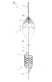
図1は、本発明の第1の実施形態に係る塞栓物質切除捕捉装置の全体概略図である。この図に示すように、本実施形態の塞栓物質切除捕捉装置100は、シャフト1と、このシャフト1に設けられる案内部3と、バスケットフィルタ5と、切除コイル7とから構成される。まず案内部3がシャフト1の先端(遠位端)に設けられ、次いでシャフト1の基端(近位端)側に向かって軸方向にバスケットフィルタ5、切除コイル7が順に配置されている。
[First Embodiment]
FIG. 1 is an overall schematic view of an embolus material excision capturing apparatus according to a first embodiment of the present invention. As shown in this figure, the embolus material
まずシャフト1は、長尺なワイヤ(スクリューワイヤ)から構成され、後述するカテーテルに挿通される。また、基端の操作によりカテーテル内を軸方向に移動可能である。このシャフト1の素材としては、ニッケルチタン系合金やステンレス鋼等の金属が適している。
First, the
シャフト1の先端(遠位端)には、可撓性を有する案内部3が設けられている。この案内部3は、血管やカテーテル内で塞栓物質切除捕捉装置100の進行を案内するため柔らかく、コイル状に巻回されたワイヤ、あるいは編み込まれたワイヤから構成されている。
A
案内部3の近位端側には、バスケットフィルタ5が配置されている。バスケットフィルタ5は、弾性または形状記憶性を有する複数の金属ワイヤ51を編み込んだメッシュからなり、図1鎖線に示すように略楕円体に形成されている。そして弾性または形状記憶性により、自由な状態では図1実線及び点線で示すように、楕円体が略中央で折り返されたパラソル型に変形する。金属ワイヤ51からなるメッシュは、血流を通す一方で塞栓物質は確実に捕捉することができる。
A
この複数の金属ワイヤ51の両端は、リング状の結束部52、53によりそれぞれ結束されている。シャフト1の先端側に位置する結束部52は、シャフト1に固定されているが、シャフト1の基端側に位置する結束部53は、シャフト1の軸方向にスライド可能に設けられている。そのためバスケットフィルタ5は、基端側結束部53が基端(近位端)側へ移動することにより、シャフト1に沿って線状に細く収縮することが可能である。また、基端側結束部53が先端側結束部52側へ移動することで、バスケットフィルタ5を構成するワイヤ51が略中央で折り返され、半径方向に拡張してパラソル型に変形する。パラソル型に変形した際、基端側連結部53は、折り返し部よりも先端側連結部52側に位置している。このように折り返されることにより、バスケットフィルタ5は二重のフィルタとなり、より確実に塞栓物質の捕捉ができるようになる。なお、パラソル型に変形した際の直径は、2.5〜3mm程度であるのが良い。
Both ends of the plurality of
バスケットフィルタ5を構成するワイヤ51は、ニッケルチタンワイヤ、チタンワイヤ、プラチナまたは金から構成されるワイヤとニッケルチタン合金の複合素材のワイヤ、金メッキを施したニッケルワイヤ、またはチタン合金のワイヤ等からなり、編まれた後にこれを熱処理して熱硬化性を持たせたものを用いる。また、ワイヤ51の直径は0.02〜0.2mm程度であるのが望ましい。
The
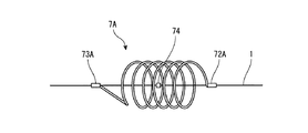
バスケットフィルタ5の近位端側には、切除コイル7が配置されている。切除コイル7は、弾性または形状記憶性を有するワイヤ71から構成される。そして自由な状態では、弾性または形状記憶性により図1に示すような螺旋形状を保持する。この切除コイル7の螺旋の数は2から5であるのが好適である。ワイヤ71の両端は、連結部72、73によりシャフト1に連結されている。シャフト1の先端側に位置する連結部72又は後端側に位置する連結部73は、シャフト1の軸方向にスライド可能である。一方、シャフト1の基端側に位置する連結部73は、シャフト1に固定されている。そのため切除コイル7は、先端側連結部72が塞栓物質切除捕捉装置100の先端側又は後端側へ移動することにより、シャフト1に沿って線状に伸長することが可能である。また、他の実施形態として、シャフト1に先端側連結部72が固定され、基端側連結部73がスライド可能であっても良い。
An
あるいは、図5に示すように、切除コイル7Aの連結部72A、73A間に、シャフト1に固定されるストッパー部材74を設け、連結部72A、73Aの両方をそれぞれスライド可能にしても良い。各連結部72A、73Aはストッパー部材74に引っ掛かるため、ストッパー部材74に位置を規制されつつも、自由に伸長、収縮することが可能となる。
Alternatively, as shown in FIG. 5, a
切除コイル7を構成するワイヤ71は、ニッケルチタンワイヤ、チタンワイヤ、プラチナまたは金から構成されるワイヤとニッケルチタン合金の複合素材のワイヤ、金メッキを施したニッケルワイヤ、またはチタン合金のワイヤ等からなる。このワイヤ71は、さらに熱処理を加えて熱硬化性を持たせても良い。また、ワイヤ71の直径は0.02〜0.1mm程度であるのが望ましい。
The
以下、上記した本実施形態の塞栓物質切除捕捉装置を使用する際の態様について、図2〜4を用いて説明する。 Hereinafter, the aspect at the time of using the above-mentioned embolus substance excision capture apparatus of this embodiment is demonstrated using FIGS.
まず、本装置を使用する前段階として、病変部20の血管21にガイドワイヤを導入する。そしてこのガイドワイヤを通して病変部20の血管21までマイクロカテーテル41を挿入し、ガイドワイヤは取り去る。
First, as a stage before using this apparatus, a guide wire is introduced into the
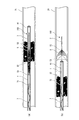
次いで、図3(a)に示すように、病変部20の血管21に挿入したマイクロカテーテル41内に塞栓物質切除捕捉装置100を通し、病変部(狭窄部)の末梢側まで移動させる。このとき、マイクロカテーテル41内で、バスケットフィルタ5の基端側結束部53はシャフト1の基端側へスライドしており、バスケットフィルタ5は線状に収縮している。同様に、切除コイル7の先端側連結部72がシャフト1の先端側へスライドしており、切除コイル7も線状に伸長している。このため、塞栓物質切除捕捉装置100はマイクロカテーテル41内をスムーズに移動できる。
Next, as shown in FIG. 3A, the embolus material
次に、図3(b)に示すように、病変部(狭窄部)の抹消側でマイクロカテーテル41の先端から塞栓物質切除捕捉装置100を突出させる。マイクロカテーテル41からバスケットフィルタ5が離脱すると、バスケットフィルタ5はその弾性もしくは形状記憶性により自動的に拡張して、パラソル型に変形し血管壁に密着する。
Next, as shown in FIG. 3 (b), the embolus material
次に、図4(a)に示すように、マイクロカテーテル41の先端から切除コイル7も取り出した後、マイクロカテーテル41を基端側へ後退させる。マイクロカテーテル41から切除コイル7が離脱すると、切除コイル7はその弾性もしくは形状記憶性により自動的に収縮して、この図に示すような本来のコイル形状に戻る。
Next, as shown in FIG. 4A, after the
次いで、図4(b)に示すように、塞栓物質切除捕捉装置100をゆっくりと基端方向へと移動させ、切除コイル7で塞栓物質22を破壊、切除の後捕捉する。切除コイル7で切除する際に取り逃した塞栓物質の遊離片23は、切除コイル7の後方に位置するバスケットフィルタ5により捕捉される。
Next, as shown in FIG. 4B, the embolic material
処置の終了後は、シャフト1を固定した状態でマイクロカテーテル41を押し出して再びマイクロカテーテル41内に塞栓物質切除捕捉装置100を収納し、マイクロカテーテル41を抜去する。
After completion of the treatment, the
なお、上記でバスケットフィルタ5の先端側結束部52をシャフト1に固定、基端側結束部53をシャフト1に対してスライド可能にすると述べたが、これに代わって、基端側結束部53をシャフト1に固定、先端側結束部52をシャフト1に対してスライド可能としても良い。あるいは、双方の結束部52、53ともスライド可能にしても良い。図6に、そのバスケットフィルタの変形例の構造を示す。バスケットフィルタ5Aの結束部52A、53Aは、シャフト1に対してスライド可能に設けられている。バスケットフィルタ5Aの略中央部では、ストッパー部材54がシャフト1に固定されている。このように構成したため、バスケットフィルタ5Aの拡張時には図6(b)に示すように基端側結束部53Aがストッパー部材54に引っ掛かり、バスケットフィルタ5Aが一定の位置に収まる。要は、バスケットフィルタ5が一定範囲の位置に拘束されつつ自由に拡張及び収縮できる構成であれば良い。
In the above description, the distal end
なお、上記の塞栓物質切除捕捉装置100は、その表面を薬剤によりコーティングされていても良い。例えば、血液凝固を防ぐ目的で抗凝固薬(例えばヘパリン)によるコーティングを施しても良い。また、親水性コーティングを行えば、血液に触れると潤滑性を発揮するようになる。そのため、血管内への挿入操作が容易になる。
The embolus material
〔第2の実施形態〕
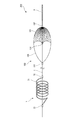
本実施形態では、第1の実施形態のパラソル型のバスケットフィルタに代えて、パラシュート型のバスケットフィルタを用いる例について説明する。図7は、本発明の第2の実施形態に係る塞栓物質切除捕捉装置の全体概略図である。また、図8は、その塞栓物質切除捕捉装置を使用する際の態様を示す模式図である。なお、第1の実施形態と同一の部分については、同一の符号を付して詳細な説明は省略する。
[Second Embodiment]
In this embodiment, an example in which a parachute basket filter is used instead of the parasol basket filter of the first embodiment will be described. FIG. 7 is an overall schematic view of an embolus material excision capturing apparatus according to a second embodiment of the present invention. FIG. 8 is a schematic view showing an aspect when the embolus material excision capturing apparatus is used. In addition, about the part same as 1st Embodiment, the same code | symbol is attached | subjected and detailed description is abbreviate | omitted.
本実施形態の塞栓物質切除捕捉装置200では、バスケットフィルタ150が弾性または形状記憶性を有する複数の金属ワイヤ151を編み込んだメッシュから構成されている。その形状は図8に示すように略楕円体だが、メッシュ部分はその楕円内の半分程度であり、この半楕円体のメッシュ部分を支持ワイヤ155が支持するパラシュートのような形状を有している。このパラシュートの傘体に当たるメッシュ部分で、血流を確保しながら塞栓物質の遊離片23等を捕捉することができる。
In the embolus material
支持ワイヤ155の近位端側は、リング状の結束部(基端側結束部)153により結束されている。また、支持ワイヤ155の遠位端側は、リング状の結束部(先端側結束部)152によりメッシュを構成するワイヤ151とともに結束されている。これらの結束部152、153はそれぞれ、シャフト1の軸方向にスライド可能に設けられている。一方、これらの結束部152、153の間には、シャフト1に固定されるストッパー部材154が配置されている。そのため、バスケットフィルタ150は、ストッパー部材154に規制される範囲でシャフト1に沿って移動することが可能である。
The proximal end side of the
よってバスケットフィルタ150は、マイクロカテーテル41内に導入された際には、図8(a)に示すようにシャフト1に沿って線状に細く収縮される。また、マイクロカテーテル41から取り出すと、図8(b)に示すように弾性または形状記憶性により自動的に半径方向に拡張してパラシュート型に変形し、血管壁に密着する。パラシュート型に変形した際の直径は2.5〜3mm程度であるのが望ましい。
Therefore, when the
バスケットフィルタ150のメッシュを構成するワイヤ151は、ニッケルチタンワイヤ、チタンワイヤ、プラチナまたは金から構成されるワイヤとニッケルチタン合金の複合素材のワイヤ、金メッキを施したニッケルワイヤ、またはチタン合金のワイヤ等からなり、編まれた後にこれを熱処理して熱硬化性を持たせたものを用いる。また、ワイヤ151の直径は0.02〜0.2mm程度であるのが望ましい。
The
なお、上記では、バスケットフィルタ150の結束部152、153をシャフト1に対してスライド可能にするとともに、この結束部152、153間にストッパー部材154を設ける構成としたが、ストッパー部材154を用いずに結束部152、153の片方を固定、他方をスライド可能な構成としても良い。要は、バスケットフィルタ150が一定範囲の位置に拘束されつつ自由に拡張及び収縮できる構成であれば良い。
In the above description, the binding
上記の塞栓物質切除捕捉装置200は、第1の実施形態と同様に、その表面を薬剤によりコーティングされていても良い。例えば、血液凝固を防ぐ目的で抗凝固薬(例えばヘパリン)によるコーティングを施しても良い。また、親水性コーティングを行えば、血液に触れると潤滑性を発揮するようになる。そのため、血管内への挿入操作が容易になる。
The embolic material
〔第3の実施形態〕
本実施形態では、第1の実施形態の一本のワイヤからなる切除コイルに代えて、複数のワイヤから構成される切除コイルを用いる例について説明する。図9は、本発明の第3の実施形態に係る塞栓物質切除捕捉装置の全体概略図である。また、図10は、その塞栓物質切除捕捉装置を使用する際の態様を示す模式図である。なお、第1の実施形態と同一の部分については、同一の符号を付して詳細な説明は省略する。
[Third Embodiment]
In the present embodiment, an example in which an ablation coil including a plurality of wires is used instead of the ablation coil including a single wire according to the first embodiment will be described. FIG. 9 is an overall schematic view of an embolus material excision capturing apparatus according to a third embodiment of the present invention. FIG. 10 is a schematic diagram showing an aspect when the embolus material excision capturing apparatus is used. In addition, about the part same as 1st Embodiment, the same code | symbol is attached | subjected and detailed description is abbreviate | omitted.
本実施形態の塞栓物質切除捕捉装置300では、切除コイル170は弾性または形状記憶性を有する複数のワイヤ171から構成されている。このワイヤ171は、自由な状態では、弾性または形状記憶性により図9に示すような螺旋形状を保持する。この複数のワイヤ171は、3〜5本用いるのが好適である(ここでは3本のワイヤ171A、171B、171Cを用いる例を示している)。ワイヤ171の螺旋の直径は2.5〜3mm程度であるのが良い。各ワイヤ171の両端は、連結部172、173によりシャフト1に連結されている。シャフト1の先端側に位置する連結部172はシャフト1の軸方向にスライド可能である。一方、シャフト1の基端側に位置する連結部173は、シャフト1に固定されている。そのため、切除コイル170は、先端側連結部172がシャフト1の先端側へ移動することにより、シャフト1に沿って線状に伸長することが可能である。よって切除コイル170は、マイクロカテーテル41内に導入された際には図10(a)に示すようにシャフト1に沿って線状に細く伸長される。また、マイクロカテーテル41から排出されると、図10(b)に示すように弾性または形状記憶性により自動的に拡張して螺旋形に変形する。そして、この拡張した切除コイル170で塞栓物質22を破壊、切除の後捕捉する。
In the embolus material
切除コイル170を構成するワイヤ171はそれぞれ、ニッケルチタンワイヤ、チタンワイヤ、プラチナまたは金から構成されるワイヤとニッケルチタン合金の複合素材のワイヤ、金メッキを施したニッケルワイヤ、またはチタン合金のワイヤ等からなる。このワイヤ171は、さらに熱処理を加えて熱硬化性を持たせても良い。また、ワイヤ171の直径は0.02〜0.1mm程度であるのが望ましい。
The wires 171 constituting the
上記の塞栓物質切除捕捉装置300は、第1、2の実施形態と同様に、その表面を薬剤によりコーティングされていても良い。例えば、血液凝固を防ぐ目的で抗凝固薬(例えばヘパリン)によるコーティングを施しても良い。また、親水性コーティングを行えば、血液に触れると潤滑性を発揮するようになる。そのため、血管内への挿入操作が容易になる。
The embolic material
なお、ここまでは主に脳梗塞治療における脳動脈や頸動脈での塞栓物質の切除及び捕捉を対象に説明してきたが、本発明の用途はこれに限らず、例えば心筋梗塞における冠動脈での塞栓物質の切除及び捕捉や、胆管における胆石の採取等、体内の種々の管腔における塞栓物質の除去に利用することができる。 Up to this point, the description has mainly focused on excision and capture of embolic substances in cerebral arteries and carotid arteries in the treatment of cerebral infarction, but the application of the present invention is not limited thereto, for example, embolization in coronary arteries in myocardial infarction It can be used for removal of embolic materials in various lumens of the body, such as excision and capture of substances, collection of gallstones in the bile ducts, and the like.
上記のように構成したため、本発明の塞栓物質切除捕捉装置によれば、バルーン等により血流を遮断することなく、血流を確保しながら処置を行えるため、患者への影響を最低限に抑えることができる。 Since it was configured as described above, according to the embolus material excision capturing device of the present invention, the treatment can be performed while securing the blood flow without blocking the blood flow with a balloon or the like, thereby minimizing the influence on the patient. be able to.
また、切除コイルとフィルタを二段構えで配置する構成としたため、塞栓物質を効率的に除去できる。特に、切除コイルの後方に配置したフィルタにより、切除コイルが取り逃した塞栓物質の遊離片をも確実に捕捉することができる。 Further, since the ablation coil and the filter are arranged in two stages, the embolic material can be efficiently removed. In particular, the filter disposed behind the ablation coil can reliably capture the free pieces of embolic material that the ablation coil has missed.
以上、本発明の実施形態について説明したが、本発明は上記実施形態に限定されるものではなく、本発明の趣旨に基づき種々の変形が可能であり、これらを本発明の範囲から排除するものではない。 As mentioned above, although embodiment of this invention was described, this invention is not limited to the said embodiment, Based on the meaning of this invention, various deformation | transformation are possible, These are excluded from the scope of the present invention. is not.
本発明は、生体の管腔における血栓等の塞栓物質を切除し捕捉するための塞栓物質切除捕捉装置に関し、産業上の利用可能性を有する。 The present invention relates to an embolus material excision capturing device for excising and capturing an embolic material such as a thrombus in a lumen of a living body, and has industrial applicability.
1 シャフト
3 案内部
5、5A、150 バスケットフィルタ
7、170 切除コイル
20 病変部
21 血管
22 塞栓物質
23 遊離片
41 マイクロカテーテル
51、151 ワイヤ
52、52A、152 先端側結束部
53、53A、153 基端側結束部
54、154 ストッパー部材
71、171 ワイヤ
72、172 先端側連結部
73、173 基端側連結部
100、200、300 塞栓物質切除捕捉装置
155 支持ワイヤ
DESCRIPTION OF
Claims (9)
先端と基端とを有し、前記先端が前記管腔の遠位端へ送り出される長尺なシャフト部材と、
該シャフト部材の先端側に設けられるとともに、前記シャフト部材に先端側と基端側で結束部において係合し、前記先端側結束部及び基端側結束部の少なくとも一方が前記シャフト部材に沿って移動することにより、装置搬送用のカテーテル内では線状に収縮し、該カテーテルから管腔内へ放出されると拡張するフィルタ部材と、
前記シャフト部材の、前記フィルタ部材より基端側に設けられるとともに、前記シャフト部材に先端側と基端側で連結部において係合し、前記先端側連結部及び基端側連結部の少なくとも一方が前記シャフト部材に沿って移動することにより、前記カテーテル内では線状に収縮し、該カテーテルから管腔内へ放出されると螺旋形に拡張するコイル部材と、を備え、
管腔内において前記コイル部材が塞栓物質を破壊、捕捉するとともに、前記塞栓物質の遊離片を前記フィルタ部材で捕捉することを特徴とする塞栓物質切除捕捉装置。 A device for removing embolic material in a lumen of a living body,
An elongate shaft member having a distal end and a proximal end, wherein the distal end is delivered to a distal end of the lumen;
The shaft member is provided at the distal end side, and is engaged with the shaft member at the binding portion on the distal end side and the proximal end side, and at least one of the distal end side binding portion and the proximal end side binding portion extends along the shaft member. A filter member that contracts linearly within the catheter for transporting the device by moving and expands when released from the catheter into the lumen;
The shaft member is provided on a proximal end side with respect to the filter member, and is engaged with the shaft member on a distal end side and a proximal end side at a coupling portion, and at least one of the distal end side coupling portion and the proximal end side coupling portion is A coil member that linearly contracts within the catheter by moving along the shaft member and expands spirally when released from the catheter into the lumen;
An embolization material excision capturing device, wherein the coil member destroys and captures an embolic material in a lumen, and a free piece of the embolic material is captured by the filter member.
前記拡張の際には、前記ストッパー部材に前記先端側結束部または基端側結束部が前記シャフト部材に沿って接近し、前記略楕円体が拡張されることを特徴とする請求項2に記載の塞栓物質切除捕捉装置。 The filter member is formed into a substantially ellipsoid from a mesh woven with a metal wire having elasticity or shape memory,
3. The substantially elliptical body is expanded according to claim 2, wherein the distal end side binding portion or the proximal end side binding portion approaches the stopper member along the shaft member during the expansion. Embolic material excision capture device.
Priority Applications (1)
| Application Number | Priority Date | Filing Date | Title |
|---|---|---|---|
| JP2008264763A JP5366497B2 (en) | 2008-10-14 | 2008-10-14 | Embolic material excision capture device |
Applications Claiming Priority (1)
| Application Number | Priority Date | Filing Date | Title |
|---|---|---|---|
| JP2008264763A JP5366497B2 (en) | 2008-10-14 | 2008-10-14 | Embolic material excision capture device |
Publications (2)
| Publication Number | Publication Date |
|---|---|
| JP2010094141A true JP2010094141A (en) | 2010-04-30 |
| JP5366497B2 JP5366497B2 (en) | 2013-12-11 |
Family
ID=42256266
Family Applications (1)
| Application Number | Title | Priority Date | Filing Date |
|---|---|---|---|
| JP2008264763A Active JP5366497B2 (en) | 2008-10-14 | 2008-10-14 | Embolic material excision capture device |
Country Status (1)
| Country | Link |
|---|---|
| JP (1) | JP5366497B2 (en) |
Cited By (7)
| Publication number | Priority date | Publication date | Assignee | Title |
|---|---|---|---|---|
| WO2011128934A1 (en) * | 2010-04-13 | 2011-10-20 | Access Point Technologies, Inc. | Embolic material excision trapping device |
| JP2012130465A (en) * | 2010-12-21 | 2012-07-12 | Shintekku:Kk | Linear member for medical treatment |
| JP2013027593A (en) * | 2011-07-29 | 2013-02-07 | Access Point Technologies Kk | Embolus capturing device |
| JP2014184026A (en) * | 2013-03-25 | 2014-10-02 | Toray Medical Co Ltd | Catheter unit |
| WO2016067646A1 (en) * | 2014-10-27 | 2016-05-06 | テルモ株式会社 | Medical device |
| JP2019500078A (en) * | 2015-11-04 | 2019-01-10 | ラピッド メディカル リミテッド | Intraluminal device |
| US10213287B2 (en) | 2014-05-16 | 2019-02-26 | Veosource Sa | Implantable self-cleaning blood filters |
Citations (10)
| Publication number | Priority date | Publication date | Assignee | Title |
|---|---|---|---|---|
| JPS6249841A (en) * | 1985-08-30 | 1987-03-04 | オリンパス光学工業株式会社 | Thrombosis removing jig |
| JPH0556148U (en) * | 1991-12-30 | 1993-07-27 | ハナコメディカル株式会社 | Filter for thrombus filtration |
| JP2000504595A (en) * | 1996-02-02 | 2000-04-18 | リージェンツ オブ ザ ユニバーシティ オブ カリフォルニア | Blood clot capture coil |
| JP2001524008A (en) * | 1997-05-08 | 2001-11-27 | エンボル−エックス・インコーポレイテッド | Percutaneous catheter and guidewire with filter and medical device deployment capabilities |
| JP2002513646A (en) * | 1998-05-01 | 2002-05-14 | マイクロ ベンション インコーポレイテッド | Embolectomy catheters and methods for treating stroke and other small vessel thromboembolisms |
| JP2002336261A (en) * | 2001-04-03 | 2002-11-26 | Medtronic Ave Inc | Temporary luminal filter guide wire and its usage |
| JP2007527264A (en) * | 2003-07-02 | 2007-09-27 | メドトロニック ヴァスキュラー インコーポレイテッド | Apparatus and method for aspirating from a filter |
| JP2008512181A (en) * | 2004-09-10 | 2008-04-24 | ピナンブラ、インク | System and method for treatment of ischemic stroke |
| WO2008084252A2 (en) * | 2007-01-11 | 2008-07-17 | Emcision Limited | Stents, devices for use with stents and methods relating thereto |
| JP3147362U (en) * | 2008-10-14 | 2008-12-25 | アクセスポイント テクノロジーズ有限会社 | Embolic material excision capture device |
-
2008
- 2008-10-14 JP JP2008264763A patent/JP5366497B2/en active Active
Patent Citations (11)
| Publication number | Priority date | Publication date | Assignee | Title |
|---|---|---|---|---|
| JPS6249841A (en) * | 1985-08-30 | 1987-03-04 | オリンパス光学工業株式会社 | Thrombosis removing jig |
| JPH0556148U (en) * | 1991-12-30 | 1993-07-27 | ハナコメディカル株式会社 | Filter for thrombus filtration |
| JP2000504595A (en) * | 1996-02-02 | 2000-04-18 | リージェンツ オブ ザ ユニバーシティ オブ カリフォルニア | Blood clot capture coil |
| JP2001524008A (en) * | 1997-05-08 | 2001-11-27 | エンボル−エックス・インコーポレイテッド | Percutaneous catheter and guidewire with filter and medical device deployment capabilities |
| JP2007222658A (en) * | 1997-05-08 | 2007-09-06 | Boston Scientific Corp | Apparatus having guidewire and filter |
| JP2002513646A (en) * | 1998-05-01 | 2002-05-14 | マイクロ ベンション インコーポレイテッド | Embolectomy catheters and methods for treating stroke and other small vessel thromboembolisms |
| JP2002336261A (en) * | 2001-04-03 | 2002-11-26 | Medtronic Ave Inc | Temporary luminal filter guide wire and its usage |
| JP2007527264A (en) * | 2003-07-02 | 2007-09-27 | メドトロニック ヴァスキュラー インコーポレイテッド | Apparatus and method for aspirating from a filter |
| JP2008512181A (en) * | 2004-09-10 | 2008-04-24 | ピナンブラ、インク | System and method for treatment of ischemic stroke |
| WO2008084252A2 (en) * | 2007-01-11 | 2008-07-17 | Emcision Limited | Stents, devices for use with stents and methods relating thereto |
| JP3147362U (en) * | 2008-10-14 | 2008-12-25 | アクセスポイント テクノロジーズ有限会社 | Embolic material excision capture device |
Cited By (12)
| Publication number | Priority date | Publication date | Assignee | Title |
|---|---|---|---|---|
| WO2011128934A1 (en) * | 2010-04-13 | 2011-10-20 | Access Point Technologies, Inc. | Embolic material excision trapping device |
| JP2012130465A (en) * | 2010-12-21 | 2012-07-12 | Shintekku:Kk | Linear member for medical treatment |
| JP2013027593A (en) * | 2011-07-29 | 2013-02-07 | Access Point Technologies Kk | Embolus capturing device |
| JP2014184026A (en) * | 2013-03-25 | 2014-10-02 | Toray Medical Co Ltd | Catheter unit |
| US10213287B2 (en) | 2014-05-16 | 2019-02-26 | Veosource Sa | Implantable self-cleaning blood filters |
| US10925707B2 (en) | 2014-05-16 | 2021-02-23 | Veosource Sa | Implantable self-cleaning blood filters |
| US10966811B2 (en) | 2014-05-16 | 2021-04-06 | Veosource Sa | Implantable self-cleaning blood filters |
| WO2016067646A1 (en) * | 2014-10-27 | 2016-05-06 | テルモ株式会社 | Medical device |
| US11083559B2 (en) | 2014-10-27 | 2021-08-10 | Terumo Kabushiki Kaisha | Collection method |
| US11918449B2 (en) | 2014-10-27 | 2024-03-05 | Terumo Kabushiki Kaisha | Medical device for collecting substances inside a body lumen |
| JP2019500078A (en) * | 2015-11-04 | 2019-01-10 | ラピッド メディカル リミテッド | Intraluminal device |
| JP7148398B2 (en) | 2015-11-04 | 2022-10-05 | ラピッド メディカル リミテッド | Intraluminal device |
Also Published As
| Publication number | Publication date |
|---|---|
| JP5366497B2 (en) | 2013-12-11 |
Similar Documents
| Publication | Publication Date | Title |
|---|---|---|
| WO2011128934A1 (en) | Embolic material excision trapping device | |
| US11648021B2 (en) | Retrieval apparatus and methods for use | |
| US9993257B2 (en) | Clot retrieval device for ischemic stroke treatment | |
| JP5059011B2 (en) | Embolic protection device | |
| JP6025846B2 (en) | Intravascular thrombus removal device and method of using the same | |
| US7044958B2 (en) | Temporary device for capturing embolic material | |
| JP5366497B2 (en) | Embolic material excision capture device | |
| JP4128526B2 (en) | Embolization prevention device | |
| EP1401354B1 (en) | Temporary intraluminal filter guidewire | |
| JP4431384B2 (en) | Intravascular devices and systems | |
| US8252018B2 (en) | Helical embolic protection device | |
| JP5164861B2 (en) | Method and apparatus for increasing blood flow through a blocked blood vessel | |
| JP5643184B2 (en) | Recovery catheter and method for recovering a deployed medical device | |
| CN112384152A (en) | Device and method for removing substance from a patient | |
| US20160015403A1 (en) | Medical retrieval devices and methods | |
| US20090198269A1 (en) | Device for the Removal of Thrombi From Blood Vessels | |
| JP2005506871A (en) | Embolic extraction tool | |
| JP2021502184A (en) | Thrombectomy device and how to use | |
| JP2004261235A (en) | Medical wire device | |
| EP3681418A1 (en) | Intravascular thromboembolectomy devices and methods | |
| JP2011516183A (en) | Multi-effect microcatheter system and method of use | |
| JP2008535588A (en) | Embolization protection filter with reduced implantation area | |
| JP2013027593A (en) | Embolus capturing device | |
| JP5749094B2 (en) | Embolization capture device | |
| JP3147362U (en) | Embolic material excision capture device |
Legal Events
| Date | Code | Title | Description |
|---|---|---|---|
| A621 | Written request for application examination |
Free format text: JAPANESE INTERMEDIATE CODE: A621 Effective date: 20111005 |
|
| A131 | Notification of reasons for refusal |
Free format text: JAPANESE INTERMEDIATE CODE: A131 Effective date: 20130326 |
|
| A521 | Request for written amendment filed |
Free format text: JAPANESE INTERMEDIATE CODE: A523 Effective date: 20130515 |
|
| TRDD | Decision of grant or rejection written | ||
| A01 | Written decision to grant a patent or to grant a registration (utility model) |
Free format text: JAPANESE INTERMEDIATE CODE: A01 Effective date: 20130830 |
|
| A61 | First payment of annual fees (during grant procedure) |
Free format text: JAPANESE INTERMEDIATE CODE: A61 Effective date: 20130910 |
|
| R150 | Certificate of patent or registration of utility model |
Ref document number: 5366497 Country of ref document: JP Free format text: JAPANESE INTERMEDIATE CODE: R150 Free format text: JAPANESE INTERMEDIATE CODE: R150 |
|
| R250 | Receipt of annual fees |
Free format text: JAPANESE INTERMEDIATE CODE: R250 |
|
| R250 | Receipt of annual fees |
Free format text: JAPANESE INTERMEDIATE CODE: R250 |
|
| R250 | Receipt of annual fees |
Free format text: JAPANESE INTERMEDIATE CODE: R250 |
|
| R250 | Receipt of annual fees |
Free format text: JAPANESE INTERMEDIATE CODE: R250 |
|
| R250 | Receipt of annual fees |
Free format text: JAPANESE INTERMEDIATE CODE: R250 |
|
| R250 | Receipt of annual fees |
Free format text: JAPANESE INTERMEDIATE CODE: R250 |
|
| R250 | Receipt of annual fees |
Free format text: JAPANESE INTERMEDIATE CODE: R250 |
|
| R250 | Receipt of annual fees |
Free format text: JAPANESE INTERMEDIATE CODE: R250 |