JP2010093809A - Optical transmission-reception unit with controllable transmission direction - Google Patents
Optical transmission-reception unit with controllable transmission direction Download PDFInfo
- Publication number
- JP2010093809A JP2010093809A JP2009231698A JP2009231698A JP2010093809A JP 2010093809 A JP2010093809 A JP 2010093809A JP 2009231698 A JP2009231698 A JP 2009231698A JP 2009231698 A JP2009231698 A JP 2009231698A JP 2010093809 A JP2010093809 A JP 2010093809A
- Authority
- JP
- Japan
- Prior art keywords
- optical
- signal
- optical transceiver
- transmission
- photodetector matrix
- Prior art date
- Legal status (The legal status is an assumption and is not a legal conclusion. Google has not performed a legal analysis and makes no representation as to the accuracy of the status listed.)
- Granted
Links
Images

Classifications
-
- H—ELECTRICITY
- H04—ELECTRIC COMMUNICATION TECHNIQUE
- H04B—TRANSMISSION
- H04B10/00—Transmission systems employing electromagnetic waves other than radio-waves, e.g. infrared, visible or ultraviolet light, or employing corpuscular radiation, e.g. quantum communication
- H04B10/11—Arrangements specific to free-space transmission, i.e. transmission through air or vacuum
- H04B10/118—Arrangements specific to free-space transmission, i.e. transmission through air or vacuum specially adapted for satellite communication
Abstract
Description
本発明は、送信方向と受信方向との間の角度を、連続的かつ自動的に測定および補償することが可能な送受信機に関する。 The present invention relates to a transceiver capable of continuously and automatically measuring and compensating an angle between a transmission direction and a reception direction.
特に、本発明は、自由空間レーザー光通信の端末器に関する。 In particular, the present invention relates to a free space laser optical communication terminal.
自由空間レーザー通信は、互いに移動し得る2点間でデータ転送のために用いられる。例えば、2つの人工衛星、人工衛星と航空機、あるいは、人工衛星と地上基地局の間等の通信に用いられる。 Free space laser communication is used for data transfer between two points that can move relative to each other. For example, it is used for communication between two artificial satellites, an artificial satellite and an aircraft, or between an artificial satellite and a ground base station.
この送信方法では、相互に通信する2つの端末機の各々が、他方の端末機へレーザービームを発出する。各端末機は同時に送信機かつ受信機であり、データは2つの端末機間の両方向に伝送し得る。データは、レーザービームのパルス形式で送信するので、適切な方法でエンコードされる。たとえ端末機の一方がある瞬間に送信するデータを持たないときでも、他方の端末機のポインティングのために用いられるビーコン信号を発出する。 In this transmission method, each of two terminals communicating with each other emits a laser beam to the other terminal. Each terminal is a transmitter and a receiver at the same time, and data can be transmitted in both directions between the two terminals. Since the data is transmitted in the form of a laser beam pulse, it is encoded in an appropriate manner. Even when one of the terminals does not have data to be transmitted at a certain moment, a beacon signal used for pointing of the other terminal is issued.
したがって、光通信端末機は、そのような信号を送信方向に発出して送信するレーザー信号送信システムを備える。さらに、受信方向という規定方向からやって来るレーザー信号を検出することを可能にする受信システムを備える。この受信方向の変化は、通信接続時における2端末機間の相対的移動、および端末機が利用されるキャリアの姿勢変化によって引き起こされる。これらの変化は、受信システムに含まれる光検出器のマトリックス上で受信されるレーザー信号の焦点の変化によって連続的に検出される。そして、端末機の送信方向の変化に従って調整して、送信信号のレーザービームが他方の端末機の受信開口を通過するようにする。端末機のこのような指向(Pointing)操作は、データの送信に対応する通信段階の時に生じる。一般に、この段階をトラッキングステップと呼ぶ。このステップの間、各端末機の指向方向は、2端末間の相対的移動およびそれぞれの姿勢移動にも拘わらず、他方の端末機の方向に維持される。 Accordingly, the optical communication terminal includes a laser signal transmission system that emits and transmits such a signal in the transmission direction. Furthermore, a receiving system is provided which makes it possible to detect a laser signal coming from a defined direction called the receiving direction. This change in the reception direction is caused by a relative movement between the two terminals at the time of communication connection and a change in the attitude of the carrier in which the terminal is used. These changes are continuously detected by changes in the focus of the laser signal received on the matrix of photodetectors included in the receiving system. Then, adjustment is performed according to the change in the transmission direction of the terminal so that the laser beam of the transmission signal passes through the reception opening of the other terminal. Such a pointing operation of the terminal occurs at a communication stage corresponding to data transmission. In general, this stage is called a tracking step. During this step, the pointing direction of each terminal is maintained in the direction of the other terminal regardless of the relative movement between the two terminals and the respective attitude movements.
より正確には、角度偏向および前方ポインティング角度(しばし前方指示角度という)を受信方向に加えることによって、送信方向が受信方向に基づいて計算される。既知の方法によって、角度偏向が、送信方向と受信方向の並列性の不足を補う。前方指示角度は、レーザー信号の往復送信期間の2端末機の相対的移動に対応する。慣性系を基準にすると、それはレーザー信号の伝播速度を2端末機のそれぞれの速度に合成することによって計算される。 More precisely, the transmission direction is calculated based on the reception direction by adding the angular deflection and the forward pointing angle (sometimes referred to as the forward pointing angle) to the reception direction. In a known manner, angular deflection compensates for the lack of parallelism in the transmission and reception directions. The forward pointing angle corresponds to the relative movement of the two terminals during the round-trip transmission period of the laser signal. With reference to the inertial system, it is calculated by combining the propagation speed of the laser signal with the respective speeds of the two terminals.
コアライメント角度(すなわち放出方向および受信方向間の角度)は、端末機が稼動状態に位置した後に(例えば端末機を機内に搭載した人工衛星が最終軌道に入ったらすぐに)測定される。この測定は一般に、端末機の温度変化に起因する変化を取り除くために、各通信セッションの前に繰り返される。この送信システムによって生成されるビームの一部を受信システムへ送信するために、格納式反射器が送信システムの送出口に一時的に置かれる。光検出器マトリックス上でのこの送信レーザービームの一部を検出することにより、コアライメント角度を測定することを可能になる。 The co-alignment angle (i.e., the angle between the emission direction and the reception direction) is measured after the terminal is in operation (e.g., as soon as the satellite with the terminal in the aircraft enters its final orbit). This measurement is generally repeated before each communication session to remove changes due to terminal temperature changes. A retractable reflector is temporarily placed at the transmission system outlet to transmit a portion of the beam generated by the transmission system to the receiving system. By detecting a portion of this transmitted laser beam on the photodetector matrix, it is possible to measure the coalignment angle.
受信したレーザー信号を集光し、且つ、送信システムによって発出されるレーザー信号を送信するために、同一の入射光学系が端末機で用いられるとき、この反射器は、入射光学系と、受信信号および送受信信号の各光路を分離する光学系と、の間に配置することができる再帰反射器である。このような分離光学系は、端末機内の送信源から発信する送信信号の光路から受信信号の光路を(光検出器マトリックスの方向に)分離する。このような再帰反射器は、既知の方法で、コーナーキューブのように配置した3枚の平面鏡の形態とすることが好ましい。実際、このような再帰反射器の反射方向は、再帰反射器の不随意な傾斜によって変化することがない。 When the same incident optical system is used in the terminal to collect the received laser signal and transmit the laser signal emitted by the transmission system, this reflector is connected to the incident optical system and the received signal. And a retroreflector that can be arranged between the optical system for separating the optical paths of the transmission and reception signals. Such a separation optical system separates the optical path of the reception signal (in the direction of the photodetector matrix) from the optical path of the transmission signal transmitted from the transmission source in the terminal. Such a retroreflector is preferably in the form of three plane mirrors arranged like a corner cube in a known manner. In fact, the reflection direction of such a retroreflector is not changed by an involuntary tilt of the retroreflector.
送信信号および受信信号の共通光路に反射器が位置するときに、コアライメント角度は測定される。そして、測定が完了すると直ぐに反射器が格納される。反射器は、端末機の光学入射視野を少なからず不明瞭にするので、このような角度偏向の測定は、トラッキング段階中に実行することができない。そして、測定された角度偏向の値は、固定トラッキングの継続期間中に用いられる。 The coalignment angle is measured when the reflector is located in the common optical path of the transmitted signal and the received signal. Then, as soon as the measurement is completed, the reflector is stored. Such a measurement of angular deflection cannot be carried out during the tracking phase, since the reflector obscures the optical incident field of the terminal at least. The measured angular deflection value is then used during the fixed tracking duration.
しかし、コアライメント角度の精密な値は、例えば温度変化の影響を受けて、連続的に変化し得る。そして、ポインティングエラーは、長期の継続期間にわたって同一のコアライメント角度値を用いることに起因する。このコアライメント角度を周期的に繰り返し測定することは、データ送信に実利用できる時間を減少させることになるだろう。 However, the precise value of the co-alignment angle can change continuously, for example under the influence of temperature changes. The pointing error is caused by using the same co-alignment angle value over a long duration. Measuring this co-alignment angle periodically and repeatedly will reduce the time actually available for data transmission.
角度偏向の精密な値を連続的に用いるために、端末機によって受信システムの光検出マトリックスへ送信される信号の一部を恒久的に反射する、ことが特許文献1で提案されている。この方法では、角度偏向の実効値を追跡段階中恒久的に測定することができる。しかし、反射される送信信号の一部は、光検出器マトリックス上で、通信接続の相手端末機から発信される信号と重ね合わされてしまう。受信データの復号において、これがエラーの原因となる。
In order to continuously use precise values of angular deflection, it is proposed in
従って、本発明の目的は、受信信号の検出を妨害することなく、追跡段階中に角度偏向の恒久的測定を可能にすることである。 The object of the invention is therefore to allow a permanent measurement of the angular deflection during the tracking phase without disturbing the detection of the received signal.
この目的のために、本発明が提案する光送受信機は以下を備える。
送信方向に第1の光信号を送信するように構成した、第1の光信号を送信するためのシステムと、
マトリックスの実用領域の各点で受光する第2の光信号を検出するよう配置し、受信システムの入射視野の内部で第2の信号の受信方向に実用領域の各点が対応している光検出器のマトリックスを備える、第2の光信号を受信するためのシステムと、
第1の信号のビームの一部を光検出器へ導く光結合システム。
For this purpose, the optical transceiver proposed by the present invention comprises:
A system for transmitting a first optical signal configured to transmit a first optical signal in a transmission direction;
Light detection in which the second optical signal received at each point in the practical area of the matrix is detected and each point in the practical area corresponds to the reception direction of the second signal within the incident field of the receiving system. A system for receiving a second optical signal comprising a matrix of vessels;
An optical coupling system that directs a portion of the beam of the first signal to the photodetector.
また、当該送受信機は、第1の信号のビームの一部を光検出器マトリックスの少なくとも1点に導くように結合システムを配置し、この1点がマトリックスの実用領域の外部で送信方向によって変化することによって特徴付けられる。 The transceiver also arranges a coupling system to direct a portion of the beam of the first signal to at least one point in the photodetector matrix, which varies with the transmission direction outside the practical area of the matrix. Is characterized by
また、当該送受信機は、第1の信号のビームの一部を検出する光検出器の少なくとも1点の座標に基づいて送信方向を決定するのに適している送信制御を備えている。 The transceiver includes transmission control suitable for determining the transmission direction based on the coordinates of at least one point of the photodetector that detects a part of the beam of the first signal.
第1の信号のビームの一部が、受信信号を検出するのに用いられる光検出器マトリックスの領域の外部へ導かれるので、受信信号と迂回される送信信号の一部との2つの検出が同時に行われる。言い換えると、第2の信号は光検出器マトリックスの実用領域内で検出され、同時に、結合システムによって光検出器マトリックスへ導かれる第1の信号の一部がマトリックスの実用領域の外部で検出される。とくに、検出される送信信号の一部は、マトリックス上で受信信号に重畳されず、受信信号を困難なく検出することができる。したがって、送信方向、したがって送信方向と受信方向間の角度偏向を、追跡段階を通じて決定することができる。そして、送信方向と受信方向の2方向間における正しい角度偏向をリアルタイムで正確に補償しながら、第1の信号の送信を実行することができる。 Since part of the beam of the first signal is directed outside the region of the photodetector matrix used to detect the received signal, there are two detections: the received signal and the part of the transmitted signal that is bypassed. Done at the same time. In other words, the second signal is detected within the practical area of the photodetector matrix, and at the same time, a portion of the first signal that is directed to the photodetector matrix by the coupling system is detected outside the practical area of the matrix. . In particular, a part of the detected transmission signal is not superimposed on the reception signal on the matrix, and the reception signal can be detected without difficulty. Thus, the transmission direction and thus the angular deflection between the transmission direction and the reception direction can be determined through the tracking phase. The first signal can be transmitted while accurately compensating for the correct angular deflection between the two directions of the transmission direction and the reception direction in real time.
さらに、追跡段階中のデータ送信を可能にする時間は、送信方向を決定するために減ることはない。 Furthermore, the time that allows data transmission during the tracking phase is not reduced to determine the transmission direction.
光検出器マトリックスの実用領域は、送受信機の取得操作中に受信システムの光学入射口に対応するものとし得る。 The practical area of the photodetector matrix may correspond to the optical entrance of the receiving system during the acquisition operation of the transceiver.
本発明の第1の改良にしたがえば、結合システムは、第1の信号のビームの一部を光検出器マトリクスの幾つかの点へ同時に導くのに適している。これらの点は、送信方向に従って変化し、マトリックスの実用領域の外部に位置する。この場合、送信制御ユニットは、第1の信号のビームの一部が検出される光検出器マトリックスの複数点の重心を計算することによって、送信方向を決定するのに好適である。したがって送信方向、あるいはコアライメント角度を、より正確に決定することができる。 According to a first refinement of the invention, the combination system is suitable for directing a part of the beam of the first signal to several points of the photodetector matrix simultaneously. These points vary according to the transmission direction and lie outside the practical area of the matrix. In this case, the transmission control unit is suitable for determining the transmission direction by calculating centroids of a plurality of points of the photodetector matrix where a part of the beam of the first signal is detected. Therefore, the transmission direction or the co-alignment angle can be determined more accurately.
本発明の第2の機能強化にしたがえば、結合システムは、互いに接続された幾つかの反射体の組立物を備える。そしてこれらの反射体は、送信方向を決定するのに用いられる第1の信号の一部を光検出器マトリックスへ反射するよう構成されている。このような実施形態は単純かつ軽量である。 According to a second enhancement of the invention, the coupling system comprises an assembly of several reflectors connected to each other. These reflectors are then configured to reflect a portion of the first signal used to determine the transmission direction to the photodetector matrix. Such an embodiment is simple and lightweight.
とくに、反射体の組立物は、3面体を形成するように配置された3枚の平面鏡を備えることができる。そして3面体の内部の開口は、3面体と共通な頂点を有するコーナーキューブを含むことができる。言い換えると、本発明に用いられる3枚の平面鏡からなる3面体は、コーナーキューブより大きい開口である。 In particular, the reflector assembly can comprise three plane mirrors arranged to form a trihedron. The opening inside the trihedron can include a corner cube having a vertex common to the trihedron. In other words, the trihedron composed of three plane mirrors used in the present invention is an opening larger than the corner cube.
結合システムのこのような構成のために、3枚の鏡のうち少なくとも1つは、受信システムの入射光学視野開口角度よりも大きい角度で、コーナーキューブの対応する面に対して傾けることができる。 Because of this configuration of the coupling system, at least one of the three mirrors can be tilted with respect to the corresponding surface of the corner cube at an angle that is larger than the incident optical field aperture angle of the receiving system.
本発明の好適な実施例では、結合システムの反射体の組立物は、コーナー状に配置され、それぞれがコーナーキューブの配置に対して同じ付加角度で傾いた3枚の平面鏡からなる。そして、検出器マトリックスの方へ向けられた第1の信号のビームの一部は、6つの個別のビームからなる。これらの個別のビームは、マトリックスの中心光軸に対して対称な方法で角度分散させることができる。この場合、光検出器マトリックスの中心光軸に関する、個別の各々の角度偏向は、反射体の組立物の各鏡の傾斜角のおよそ4.6倍である。 In a preferred embodiment of the invention, the reflector assembly of the coupling system consists of three plane mirrors arranged in a corner, each inclined at the same additional angle with respect to the corner cube arrangement. And the part of the beam of the first signal directed towards the detector matrix consists of 6 individual beams. These individual beams can be angularly dispersed in a symmetric manner with respect to the central optical axis of the matrix. In this case, each individual angular deflection with respect to the central optical axis of the photodetector matrix is approximately 4.6 times the tilt angle of each mirror of the reflector assembly.
本発明の第3の機能拡張にしたがえば、結合システムは、結合システムによって光検出器マトリックスへ導かれた第1の信号のビームの一部を減衰するためのデバイスをさらに備えることができる。このような減衰デバイスは、第1の信号のビームのこの一部の出力を調節する。したがって、結合システムによって折り返される第1の信号のビームの一部が、検出点における検出器マトリックスが飽和するのを防ぐことが可能である。特に、減衰デバイスが吸収板を備えるとすることができる。 In accordance with the third enhancement of the present invention, the coupling system can further comprise a device for attenuating a portion of the beam of the first signal directed by the coupling system to the photodetector matrix. Such an attenuation device adjusts the output of this part of the beam of the first signal. Thus, the part of the beam of the first signal that is folded by the coupling system can prevent the detector matrix at the detection point from becoming saturated. In particular, the attenuation device may comprise an absorption plate.
本発明の第4の機能拡張にしたがえば、結合システムは、反射体の組立物によって発生して検出器マトリックスの実用領域の内部に到達し得る迷光信号を抑制するためのデバイスも備えることができる。このような抑制デバイスは、特に、迷光信号を遮るよう置かれた絞りを備えることができる。 According to a fourth enhancement of the invention, the coupling system may also comprise a device for suppressing stray light signals that can be generated by the reflector assembly and reach the inside of the working area of the detector matrix. it can. Such a suppression device can in particular comprise an aperture placed to block stray light signals.
本発明の他の特別な特徴および利点が、幾つかの非限定的な実施例についての以下の説明に、添付図面を参照して示される。 Other special features and advantages of the present invention are set forth in the following description of some non-limiting examples with reference to the accompanying drawings.
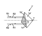
本発明に用いることができる再帰反射器を理解するのを容易にするために、先行技術の既知なる再帰反射器を、図1aを参照しながらはじめに説明する。この再帰反射器(全体的参照番号1’)は、3枚の平面鏡1a’,1b’,1c’からなる。各平面鏡は、直角2等辺3角形の形を有している。これら鏡はコーナーキューブを形成するよう配置され、互いの辺を切れ目なく配置し、それぞれの直角はΣで印された頂点を共に形成する。この状況では、再帰反射器1’の開口に入射する光線R1またはR2は、3枚の鏡1a’,1b’,1c’によって順次反射することによって、自分自身と平行に射出する。各光線の射出方向は、3枚の鏡1a’,1b’,1c’を光線が反射する順番によらない。実際には、3枚の鏡面でなく、1枚または2枚の鏡面以外で反射しない光線が再帰反射器に入射するのを妨げるために、各鏡1a’,1b’,1c’の頂点Σに位置しない2角は切除される。この方向で干渉する再帰反射器の有効開口は6角形である。明快さのために、図1aおよび図2bは、当業者には既知であるこのような再帰反射鏡の切断は示していない。
In order to facilitate understanding of retroreflectors that can be used in the present invention, a known prior art retroreflector will first be described with reference to FIG. 1a. This retroreflector (general reference number 1 ') comprises three
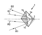
図1bは、本発明を実施するのに用いることができる再帰反射器を示した図である。この再帰反射器は、全体参照番号1を付与し、やはり3枚の平面鏡1a,1b,1cを備える。再帰反射器1の機構は、 再帰反射器の開口方向に頂点Σを移動させることによって、図1’の再帰反射器1’から導出することができる。したがって、3枚の鏡1a,1b,1cによって形成される3面体は、頂点Σを平行移動させたとき、コーナーキューブのものよりも大きな内部開口を有する。
FIG. 1b illustrates a retroreflector that can be used to practice the present invention. This retroreflector is given the
この状況では、再帰反射器1に入射する光線R1は、その入射方向とは異なる方向に射出する。加えて、入射方向に関連する射出方向の方位は、3枚の鏡1a,1b,1cが光線を順次反射する順番に依存する。この目的のために、図1bでは、2光線R1、R2の軌跡が比較されている。したがって、再帰反射器1によって反射される同一の入射ビームが、3枚の鏡1a,1b,1cの傾きに応じて角度分解された幾つかの反射ビームに分離される。反射ビームは、3枚の鏡1a,1b,1cを反射する順序によって区別される。したがって、図1bの再帰反射器1の機構は、同一の入射ビームから反射される6つのビームを発出する。
In this situation, the light ray R1 incident on the
図1bの再帰反射器1の3枚の鏡1a,1b,1cは、対称的に向きを変えられており、各々が対応する3枚の鏡1a’,1b’,1c’に関連している。この場合、6つの反射ビームは、入射ビームの方向を中心とした円錐状に対照的分布をしている。そして、その頂点の半角は、コーナーキューブに関連して、再帰反射器の鏡の角度傾斜によって決定される。頂点におけるこの半角は、3枚の鏡面の共通傾斜角を4.6倍したものに実質的に等しい。
The three
しかしながら、鏡1a,1b,1cのうち少なくとも1つが、再帰反射器1の開口に含まれるコーナーキューブの対応する面に関して向きを変えることが、本発明にとって十分である。
However, it is sufficient for the present invention that at least one of the
以下に説明するように、本発明を適用するために方向を変える再帰反射器の鏡の角度傾斜の値(コーナーキューブの対応する面に関して)は、再帰反射器によって反射される送信ビームの一部が、反射システムの入射光学視野の開口半角よりも大きく偏向して反射されるように選ばれる。 As described below, the value of the retroreflector mirror's angular tilt (with respect to the corresponding face of the corner cube) that changes direction to apply the present invention is the fraction of the transmitted beam reflected by the retroreflector. Is selected to be deflected and reflected more than the half aperture of the incident optical field of the reflection system.
例証として、これより本発明を、レーザービームによる通信の文脈にて説明する。したがって、本発明を適用する送信機は、自由空間のレーザー光通信端末機である。 By way of example, the invention will now be described in the context of laser beam communication. Therefore, the transmitter to which the present invention is applied is a laser optical communication terminal in free space.
図2から図5は、本発明に従う3つの自由空間のレーザー光通信端末機を説明する図である。これらの図では、同一の参照番号を同一または同一の機能を有する要素に割り当てる。これらの図は、用いられる光学原理を説明する図であり、当業者が各実施例を再現することを可能にする。以下では、3つの自由空間のレーザー光通信端末機のうち、既知であり本発明によって変更されないものについては繰り返して説明をしない。 2 to 5 are diagrams illustrating three free space laser optical communication terminals according to the present invention. In these figures, the same reference numbers are assigned to elements having the same or the same function. These figures illustrate the optical principle used and allow those skilled in the art to reproduce each embodiment. In the following, among the three free space laser optical communication terminals, those which are known and are not modified by the present invention will not be described repeatedly.
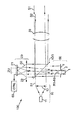
各端末機はレーザー信号送信システム10とレーザー信号受信システム20とを備える。一般に、送信システム10は、レーザー信号源11とコリメーション光学系12とを備える。受信システム20は、光検出器マトリックス21と集光光学系22とを備える。マトリックス21は、光学系22の結像面に位置する。参照番号100は端末機の全体を示す。
Each terminal includes a laser
信号源11によって生成された信号のレーザービームに符号S1が振られている。信号源11および光学系12は、光学系12の後段でビームS1が平行構造であるよう配置されていることが好ましい。端末機100の外部の別の光通信端末機からのものであり、端末機によって受信する信号のレーザービームに符号S2が振られている。以下の説明では、簡単のために、S1およびS2でそれぞれ送信信号および受信信号を示し、これらは発明の概要において第1の光信号および第2の光信号と呼んだものである。。
Reference numeral S <b> 1 is applied to the laser beam of the signal generated by the signal source 11. The signal source 11 and the
3つの実施形態(しかし本発明において必要不可欠ではない様式)では、説明した端末機の各々は、送信システムおよび受信システムに対して共通の光学入射口を有する。望遠鏡レンズとし得る、この光学入射口は、その機構の詳細を示すことなく、全体参照番号30を割り当てる。そして、各端末機は、一方では光学入射口30と送信源11との間であり、かつ一方では光学入射口30と光検出器マトリックス21との間に位置する光学分離システム40を備える。半反射板とし得る、分離システム40は、信号源11によって生成された信号S1を光学入射口30に送信し、光学入射口を通過する受信信号S2を光検出器マトリックスに送信するよう構成されている。詳しくは、光学入射口30は、送信システム10および受信システム20の両方に機能的に属している。送信光路および受信光路にとって共通の光学入射口を有する光通信端末機のこのような機構にとって、本発明により導入される結合システムは、光検出マトリックスへ導かれる送信信号S1のビームの一部のために再帰反射器を形成する。
In three embodiments (but not in the manner essential to the present invention), each of the terminals described has a common optical entrance for the transmission system and the reception system. This optical entrance, which may be a telescope lens, is assigned the
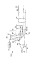
図2によれば、端末機100は、光学入射口30と光学分離システム40との間に位置する再帰反復器1を、送信信号S1および受信信号S2に共通する光路断面に備える。再帰反復器1は図1bに示される種類とすることができる。大きな割合で送信信号がビームS1を遮蔽するのを防ぐために、再帰反復器1の横断面積は小さいことが好ましい。
Referring to FIG. 2, the terminal 100 includes the
したがって、再帰反射器1は送信信号S1のビームの一部を選択し、それぞれR1からR6で参照される6つの2次ビームを形成して反射する。ビームR1−R6は半反射板40を反射し、そして集光光学系を経由して光検出器マトリックスへ向かう。そしてビームの各々は、マトリックス21上で集光点を形成し、集光点の位置は、システム10の送信方向に依存する。
Therefore, the
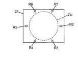
さらに、反射されたビームR1−R6のそれぞれの方向は、図1bを参照して上記説明をした方法で、お互いに角度に関してオフセットされる。このオフセットの結果として、ビームR1−R6によってマトリックス21上に形成される集光点は、図5に示されるように、受信信号S2の検出に専用のマトリックスの中央領域の外側に位置する。信号S2の検出に専用のマトリックス21の中央領域は、符号ZUで示され、実用領域と呼ばれる。実用領域ZUの各点は、受信システム20の入力視野の中で、信号S2の識別的受信方向に対応する。実用領域ZUは、追跡段階中に、あるいは好ましくは補足段階中に、用いられるマトリックス21の領域であり得る。第1の場合、明白な角直径は、数十マイクロラジアンであり得、第2の場合、数ミリラジアンである。実用領域ZUの外側のビームR1−R6に対応する集光点のオフセットは、再帰反射器1の鏡1a−1cの傾斜によって確定する。例えば、およそ0.5mrad(マイクロラジアン)よりも大きい角度傾斜を3枚の鏡1a,1b,1cに均等に適用することにより、受信システムの射出視野の半開口角の2.5mradに対応する実用領域ZUの外に、ビームR1−R6の集光点を位置づけることが可能になる。
Furthermore, the respective directions of the reflected beams R1-R6 are offset with respect to each other in the manner described above with reference to FIG. 1b. As a result of this offset, the focal points formed on the
ビームR1−R6の各集光点は、ビームS1の平行度合いに応じて、マトリックス21の単一光検出器または幾つかの光検出器に対応する。各集光点に対して中心点が決定し、そして集光点のそれぞれの中心点の重心が計算される。そして重心の座標がシステム10の送信方向を特徴付ける。このように決定された送信方向と信号S2の受信方向(実用領域ZU内で信号の衝突する点によって特徴付けられる)との間のオフセットはコアライメント角度である。
Each focusing point of the beams R1-R6 corresponds to a single photodetector or several photodetectors of the
この目的のために、光検出器マトリックス21によって作り出される、ビームR1−R6の検出信号は、CTRLと印された送信コントローラー60に送信することがきる。コントローラー60は、ビームR1−R6の検出点の重心を計算することによって、送信方向を決定する。また送信システム10は、実際の送信方向を変更するように配置された(図示しない)可変偏向器を含むこともできる。そして、コントローラー60は、決定されたコアライメント角度を補償するために、この可変偏向器を制御することができる。したがって、マトリックス21の実用領域ZUで信号S2が検出されると同時に、システム10のそれぞれの送信方向とシステム20の受信方向との間のコアライメント角度が決定され、リアルタイムで補償される。
For this purpose, the detection signals of the beams R1-R6 produced by the
また、マトリックス21上でビームR1−R6の集光点の強度を低減するために、吸収板2を再帰反射器1の開口の直前に配置できることが好ましい。吸収板2は、光検出器の検出範囲内に、マトリックス21上でのビームR1−R6の強度を調整することを可能にする。
Further, it is preferable that the absorbing
再帰反射器1および吸収板2は共に、発明の概要で記載した結合システム50を形成する。したがって、吸収板2は、結合システム50によって反射されるビームを減衰する機能を有する。
Together, the
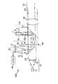
図3によって図解される本発明の第2実施形態が、図2の第1実施形態において、信号S1および信号S2に共通する光路断面の外部の再帰反射器1を移動させることにより構成することができる。第2実施形態の利点は、再帰反射されるビームS1の割合がもはや、再帰反射器の断面と送信ビームS1の大きさとの比率によってのみ決定されるものではないということである。この場合、結合システム50は、また、光学入射口30と光学分離システム40との間に位置する反射デバイス3を、信号S1および信号S2の光路の共通断面上に備える。反射デバイス3は、信号S1のビームの一部を再帰反射器1へ向けるよう配置されている。例えば、反射デバイスは半反射板を備えることができる。この場合、半反射板は、その端部がマトリックス21の実用領域ZUに到達しうる迷光信号を発生するのを防ぐために、ビームS1の全体の断面に広がっていることが好ましい。あるいは、半反射板は、信号S1のビームの断面積の一部だけに広がっていることもできる。
The second embodiment of the present invention illustrated by FIG. 3 can be configured by moving the
最後に、図4によって図解される本発明の第3実施形態は、図3の第2実施形態において、半反射板40および半反射板3の機能を組み合わせることによって構成することができる。言い換えると、信号S1と信号S2とを分離するためのシステムは、送信方向を決定するのに用いる信号S1のビームの一部を反射器に送信するように構成されている。当業者であれば、第1および第2の実施形態について上記に与えた説明および図4に照らして考えれば第3実施形態の稼動方法を理解することができるだろう。
Finally, the third embodiment of the present invention illustrated by FIG. 4 can be configured by combining the functions of the
図3および図4の実施形態の改良によれば、結合システム50は、また、反射器の直前に位置する絞り4を備えることができる。このような絞りは、反射器によって発生し、光検出器マトリックス21の実用領域ZU内に到達し得る迷光信号を阻止する。このような迷光信号は、鏡1a,1b,1cの拡散縁によって、顕著に発生し得る。同じ理由により、鏡1a,1b,1cの縁部の遮蔽物を、図2の本発明の実施形態に付け加えることができる。したがって、このような絞り又は遮蔽物は、反射器によって発生する迷光信号を抑制する機能を有する。
According to an improvement of the embodiment of FIGS. 3 and 4, the
一般に、端末機100の外部に実際に送信される信号S1の出力を本質上減らさないように、信号S1のビームの減らされた方の部分を、結合システム50が受信システム20へ導くことが好ましい。したがって、結合システム50は、光検出器マトリックス21へ向けられる信号S1のビームの割合が、送信システム10によって生成する信号S1の出力との割合で、3%以下、好ましくは1%以下が好ましい。
In general, it is preferable for the combining
結合システムが、たとえば鏡1a,1b,1c等の反射器を備え、図2に示されるように信号S1および信号S2に共通の光路に組み込まれるとき、結合システムは、ビームS1およびビームS2の大きさよりもかなり小さい横断面積としなければならない。再帰反射器1の横断面積は、およそ5mmまたは3mmよりも小さい再帰反射器の直径にそれぞれ対応して、20mm2よりも小さいことが好ましく、さらには7mm2より小さいことが好ましい。図3および図4によって図解される本発明の実施形態のように、信号S1および信号S2に共通する光路の外側に再帰反射器1を移動した場合、この制限は存在しなくなる。そして、再帰反射されたビームS1の割合は、半反射板3の特性によって調整され得る。
When the coupling system is provided with reflectors such as
上記に詳説した実施形態を変更することによって、言及した利点の少なくとも幾つかを維持したまま本発明を再現することができることが理解される。これらの利点に共通して、本発明は、端末機の送信方向および受信方向間のアライメントの差の実効値を恒久的に決定することを可能にする。そしてこの差は、連続的方法で正確に補償されることができる。 It will be appreciated that by modifying the embodiments detailed above, the present invention can be reproduced while maintaining at least some of the advantages mentioned. In common with these advantages, the present invention makes it possible to permanently determine the effective value of the alignment difference between the transmission direction and the reception direction of the terminal. This difference can then be accurately compensated in a continuous manner.
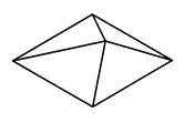
導入され得る変更として、結合デバイスの機構を変えることができる。図6aおよび図6bは、ピラミッド状に置かれた幾つかの平面鏡からなる2つの反射器を表している。特に、ピラミッドの側面の数は変更し得る(図6aでは4、図6bでは6)。しかしながら、図1bの3面体の反射器機構が好ましい。なぜなら、一般的な傾きの反射器の構成よりも本発明の操作に関する鋭敏さを小さくできるからである。 As a change that can be introduced, the mechanism of the coupling device can be changed. Figures 6a and 6b represent two reflectors consisting of several plane mirrors placed in a pyramid. In particular, the number of sides of the pyramid can be varied (4 in FIG. 6a, 6 in FIG. 6b). However, the trihedral reflector mechanism of FIG. 1b is preferred. This is because the sensitivity of the operation of the present invention can be made smaller than that of a general tilt reflector configuration.
コーナーキューブに基づいて反射器を設計したとき、鏡のうち1つまたは2つが立方体の面に関して方向を変えるようにすることができる。さらに、同一の入射ビームから幾つかの反射ビームを生成する再帰反射器は、図1aによるコーナーキューブの標準的再帰反射器に屈折プリズムを組み合わせることによっても得ることができる。 When designing a reflector based on a corner cube, one or two of the mirrors can change direction with respect to the face of the cube. Furthermore, a retroreflector that produces several reflected beams from the same incident beam can also be obtained by combining a refractive prism with a corner cube standard retroreflector according to FIG. 1a.
また、結合システムは、端末機100の入力レンズの直前または直後の送信信号S1および受信信号S2の共通光路に位置することもできる。 In addition, the coupling system may be located in the common optical path of the transmission signal S1 and the reception signal S2 immediately before or after the input lens of the terminal 100.
最後に、自由空間レーザー通信の文脈で本発明の詳細な説明を行ってきたが、如何なる他の光学送受信機においても同様に本発明を適用することがきる。そして当業者であるならば、例えば光学結合システムの大きさ等のある種の特性を、用いる送受信機のモードにて、受信する波長および放射エネルギー密度に合わせて調整することが可能である。 Finally, although the present invention has been described in detail in the context of free space laser communications, the present invention can be applied to any other optical transceiver as well. A person skilled in the art can adjust certain characteristics, such as the size of the optical coupling system, for example, in the mode of the transceiver used, according to the received wavelength and radiant energy density.
Claims (20)
第2の光信号を受信するための受信システムと、
光結合システムとを備え、
前記送信システムは、送信方向に前記第1の光信号を送信するよう構成され、
前記受信システムは、実用領域のある点で受信される前記第2の光信号を検出するように配置された光検出器マトリックスを備え、
前記実用領域の各点は、前記受信システムの入射光学視野内における前記第2の光信号の受信方向に対応し、
前記光結合システムは、前記第1の光信号のビームの一部を前記光検出器マトリックスへ向ける、
光送受信機において、
前記光結合システムは、前記第1の光信号のビームの前記一部を前記光検出器マトリックスの少なくとも1点の方へ向けるように配置され、
前記少なくとも1点は、前記送信方向に依存して変化し、且つ、前記光検出器マトリックスの前記実用領域の外部に位置し、
前記光送受信機は、前記光検出マトリックスの前記少なくとも1点の座標に基づいて、前記送信方向を決定するよう構成された送信制御ユニットをさらに備える、
ことを特徴とする光送受信機。 A transmission system for transmitting the first optical signal;
A receiving system for receiving a second optical signal;
An optical coupling system,
The transmission system is configured to transmit the first optical signal in a transmission direction;
The receiving system comprises a photodetector matrix arranged to detect the second optical signal received at a point in service area,
Each point in the practical area corresponds to the receiving direction of the second optical signal in the incident optical field of the receiving system;
The optical coupling system directs a portion of the beam of the first optical signal to the photodetector matrix;
In an optical transceiver,
The optical coupling system is arranged to direct the portion of the beam of the first optical signal toward at least one point of the photodetector matrix;
The at least one point varies depending on the transmission direction and is located outside the practical area of the photodetector matrix;
The optical transceiver further comprises a transmission control unit configured to determine the transmission direction based on the coordinates of the at least one point of the light detection matrix;
An optical transceiver characterized by that.
前記幾つかの点は、前記光検出器マトリックスの前記実用領域の外部に位置し、前記送信方向にしたがって変化し、
前記送信制御ユニットは、前記第1の信号のビームの前記部分を検出する前記光検出器マトリクスの前記点の重心を計算することにより前記送信方向を決定するよう構成されたことを特徴とする、請求項1から請求項3の何れか1つに記載の光送受信機。 The combining system directs the portion of the beam of the first signal simultaneously to several points of the photodetector matrix;
The several points are located outside the practical area of the photodetector matrix and vary according to the transmission direction,
The transmission control unit is configured to determine the transmission direction by calculating a centroid of the point of the photodetector matrix that detects the portion of the beam of the first signal, The optical transceiver according to any one of claims 1 to 3.
前記3面体は、該3面体に共通の頂点を有するコーナーキューブを含む内部開口を有することを特徴とする、請求項5から請求項9の何れか1つに記載の光送受信機。 The reflector includes three plane mirrors arranged to form a trihedron,
The optical transceiver according to any one of claims 5 to 9, wherein the trihedron has an internal opening including a corner cube having a vertex common to the trihedron.
前記光送受信機は、一方で前記光学入射口と前記第1の信号の送信源との間であり、他方で前記光学入射口と前記光検出器マトリックスとの間に位置する光学分離システムをさらに備え、
前記光学分離システムは、前記送信源によって発出した前記第1の信号を前記光学入射口へ送信し、前記第2の信号が前記光学入射口から前記光検出器マトリックスへ通過するように構成され、
前記結合システムは、前記光検出器マトリックスへ向けられた前記第1の信号のビームの前記一部に対する再帰反射器を形成することを特徴とする、請求項1から請求項12の何れか1つに記載の光送受信機。 The optical transceiver has an optical entrance common to the transmission system and the reception system,
The optical transceiver further includes an optical separation system located on the one hand between the optical entrance and the source of the first signal and on the other hand located between the optical entrance and the photodetector matrix. Prepared,
The optical separation system is configured to transmit the first signal emitted by the transmission source to the optical entrance and pass the second signal from the optical entrance to the photodetector matrix;
13. Any one of claims 1 to 12, wherein the coupling system forms a retroreflector for the portion of the beam of the first signal that is directed to the photodetector matrix. The optical transceiver described in 1.
前記反射器は、前記共通光路断面の外に位置し、
前記反射デバイスは、前記第1の信号のビームの前記一部を前記反射器へ向けるように配置されていることを特徴とする、請求項5を引用する請求項13に記載の光送受信機。 The coupling system comprises a reflective device located in a common optical path section of the first signal and the second signal between the optical entrance of the optical transceiver and the optical separation system,
The reflector is located outside the common optical path section;
14. The optical transceiver according to claim 13, wherein the reflective device is arranged to direct the part of the beam of the first signal to the reflector.
Applications Claiming Priority (2)
| Application Number | Priority Date | Filing Date | Title |
|---|---|---|---|
| FR0856748A FR2936893B1 (en) | 2008-10-06 | 2008-10-06 | OPTICAL TRANSMIT RECEIVING ASSEMBLY WITH CONTROL OF TRANSMISSION DIRECTION |
| FR0856748 | 2008-10-06 |
Publications (2)
| Publication Number | Publication Date |
|---|---|
| JP2010093809A true JP2010093809A (en) | 2010-04-22 |
| JP4976474B2 JP4976474B2 (en) | 2012-07-18 |
Family
ID=40640204
Family Applications (1)
| Application Number | Title | Priority Date | Filing Date |
|---|---|---|---|
| JP2009231698A Active JP4976474B2 (en) | 2008-10-06 | 2009-10-05 | Optical transceiver for transmission direction control |
Country Status (6)
| Country | Link |
|---|---|
| US (1) | US8588617B2 (en) |
| EP (1) | EP2173042B1 (en) |
| JP (1) | JP4976474B2 (en) |
| AT (1) | ATE505862T1 (en) |
| DE (1) | DE602009001081D1 (en) |
| FR (1) | FR2936893B1 (en) |
Families Citing this family (8)
| Publication number | Priority date | Publication date | Assignee | Title |
|---|---|---|---|---|
| FR3001049B1 (en) * | 2013-01-11 | 2015-02-06 | Thales Sa | DEVICE FOR OPTICALLY CONTROLLING AN IMAGING SYSTEM |
| US9800332B2 (en) * | 2013-12-27 | 2017-10-24 | Space Photonics, Inc. | Acquisition, tracking, and pointing apparatus for free space optical communications with moving focal plane array |
| FR3075522B1 (en) * | 2017-12-19 | 2020-04-03 | Airbus Defence And Space Sas | FURTIVE TRANSMISSION BETWEEN A SOURCE OF A SATELLITE OR AIRCRAFT AND A REMOTE RECEIVER |
| FR3092675B1 (en) * | 2019-02-08 | 2021-02-19 | Airbus Defence & Space Sas | INJECTION OF A RADIATION BEAM INTO AN OPTICAL FIBER |
| US11258514B2 (en) | 2020-07-10 | 2022-02-22 | Blue Cubed, Llc | Aligning single-aperture optical transceiver and method |
| FR3112659B1 (en) | 2020-07-20 | 2022-07-15 | Airbus Defence & Space Sas | OPTICAL COMMUNICATION TERMINAL BY LASER SIGNALS |
| KR102506809B1 (en) * | 2021-08-25 | 2023-03-06 | 고려대학교 산학협력단 | Apparatus based on wireless optical communication |
| WO2023113419A1 (en) * | 2021-12-15 | 2023-06-22 | 고려대학교 산학협력단 | Method and device for optimizing beam-pointing in wireless optical communication system |
Citations (4)
| Publication number | Priority date | Publication date | Assignee | Title |
|---|---|---|---|---|
| JPH06214010A (en) * | 1993-01-19 | 1994-08-05 | A T R Koudenpa Tsushin Kenkyusho:Kk | Alignment system for optical communication apparatus optical system |
| JPH0879175A (en) * | 1994-09-06 | 1996-03-22 | Sony Corp | Optical space transmission device |
| JP2005333207A (en) * | 2004-05-18 | 2005-12-02 | Canon Inc | Two-way optical space transmission apparatus |
| JP2006146223A (en) * | 2004-11-18 | 2006-06-08 | Eads Astrium Sas | Optical splitter and optical communication terminal comprising the same |
Family Cites Families (29)
| Publication number | Priority date | Publication date | Assignee | Title |
|---|---|---|---|---|
| US3942894A (en) * | 1974-11-20 | 1976-03-09 | The United States Of America As Represented By The Secretary Of The Air Force | Self referencing retransmitting alignment sensor for a collimated light beam |
| GB8801008D0 (en) * | 1988-01-18 | 1988-02-17 | British Aerospace | Acquisition system for multiple access optical communication system |
| US5517016A (en) * | 1994-03-31 | 1996-05-14 | The United States Of America As Represented By The Administrator Of The National Aeronautics And Space Administration | Lasercom system architecture with reduced complexity |
| US5592320A (en) * | 1994-08-15 | 1997-01-07 | Hughes Aircraft Company | Satellite communications system |
| US5953146A (en) * | 1997-01-30 | 1999-09-14 | At&T Corp. | Method and apparatus for tracking alignment in wireless optical communications |
| US6507424B2 (en) * | 1997-10-24 | 2003-01-14 | Canon Kabushiki Kaisha | Optical space communication apparatus |
| JPH11308174A (en) * | 1998-04-20 | 1999-11-05 | Sony Corp | Mirror holding body and optical axis correction device using the body |
| US6118131A (en) * | 1998-05-11 | 2000-09-12 | Astro Terra Corporation | Directional optics for a system for directing a laser beam toward an active area |
| JPH11352387A (en) * | 1998-06-05 | 1999-12-24 | Sony Corp | Optical axis correcting device |
| JP2000049708A (en) * | 1998-07-30 | 2000-02-18 | Sony Corp | Optical axis correction device/method |
| AU2001266570A1 (en) * | 2000-05-09 | 2001-11-20 | Teraconnect, Inc. | Self aligning optical interconnect with multiple opto-electronic devices per fiber channel |
| US6915080B2 (en) * | 2000-09-20 | 2005-07-05 | Mark David Heminger | Method and apparatus for aligning optical wireless links |
| US7133617B2 (en) * | 2000-09-20 | 2006-11-07 | Texas Instruments Incorporated | Reflection detection in an optical wireless link |
| US6839519B1 (en) * | 2000-09-29 | 2005-01-04 | Motorola, Inc. | Laser crosslink methods and apparatus |
| US20020131121A1 (en) * | 2001-03-13 | 2002-09-19 | Muthu Jeganathan | Transceiver, system, and method for free-space optical communication and tracking |
| US20020171896A1 (en) * | 2001-05-21 | 2002-11-21 | Lightpointe Communications, Inc. | Free-space optical communication system employing wavelength conversion |
| US7236706B2 (en) * | 2002-03-12 | 2007-06-26 | Canon Kabushiki Kaisha | Free space optics communication apparatus and free space optics communication system |
| US7643755B2 (en) * | 2003-10-13 | 2010-01-05 | Noble Peak Vision Corp. | Optical receiver comprising a receiver photodetector integrated with an imaging array |
| US7292788B2 (en) * | 2003-01-31 | 2007-11-06 | Lockheed Martin Corporation | Multi-beam laser communications system and method |
| US7292789B1 (en) * | 2003-04-10 | 2007-11-06 | Lockheed Martin Corporation | Multi-channel wide-field laser communications method and apparatus |
| US7403719B2 (en) * | 2003-06-30 | 2008-07-22 | Texas Instruments Incorporated | Feedback control for free-space optical systems |
| US7689127B1 (en) * | 2004-04-15 | 2010-03-30 | Lockheed Martin Corporation | Deformable mirrors for multi-access laser communications terminal |
| JP4371910B2 (en) * | 2004-05-31 | 2009-11-25 | キヤノン株式会社 | Optical space transmission equipment |
| US7587141B2 (en) * | 2005-08-02 | 2009-09-08 | Itt Manufacturing Enterprises, Inc. | Communication transceiver architecture |
| WO2008023583A1 (en) * | 2006-08-21 | 2008-02-28 | Panasonic Corporation | Optical space transmission device using image sensor |
| US7545562B2 (en) * | 2007-02-07 | 2009-06-09 | Raytheon Company | Common-aperture optical system incorporating a light sensor and a light source |
| US7711441B2 (en) * | 2007-05-03 | 2010-05-04 | The Boeing Company | Aiming feedback control for multiple energy beams |
| US8009991B2 (en) * | 2007-10-24 | 2011-08-30 | Hewlett-Packard Development Company, L.P. | Dynamic optical signal tracking on a detector array in a free space optical communication system |
| US20120121271A1 (en) * | 2010-11-12 | 2012-05-17 | Wood Thomas H | Method And Apparatus Of Free-Space Optical Signal Reception Having Enhanced Performance In Scattering Environments |
-
2008
- 2008-10-06 FR FR0856748A patent/FR2936893B1/en not_active Expired - Fee Related
-
2009
- 2009-10-05 AT AT09172199T patent/ATE505862T1/en not_active IP Right Cessation
- 2009-10-05 EP EP09172199A patent/EP2173042B1/en active Active
- 2009-10-05 JP JP2009231698A patent/JP4976474B2/en active Active
- 2009-10-05 DE DE602009001081T patent/DE602009001081D1/en active Active
- 2009-10-06 US US12/574,404 patent/US8588617B2/en active Active
Patent Citations (4)
| Publication number | Priority date | Publication date | Assignee | Title |
|---|---|---|---|---|
| JPH06214010A (en) * | 1993-01-19 | 1994-08-05 | A T R Koudenpa Tsushin Kenkyusho:Kk | Alignment system for optical communication apparatus optical system |
| JPH0879175A (en) * | 1994-09-06 | 1996-03-22 | Sony Corp | Optical space transmission device |
| JP2005333207A (en) * | 2004-05-18 | 2005-12-02 | Canon Inc | Two-way optical space transmission apparatus |
| JP2006146223A (en) * | 2004-11-18 | 2006-06-08 | Eads Astrium Sas | Optical splitter and optical communication terminal comprising the same |
Also Published As
| Publication number | Publication date |
|---|---|
| EP2173042A1 (en) | 2010-04-07 |
| JP4976474B2 (en) | 2012-07-18 |
| DE602009001081D1 (en) | 2011-05-26 |
| US8588617B2 (en) | 2013-11-19 |
| FR2936893A1 (en) | 2010-04-09 |
| EP2173042B1 (en) | 2011-04-13 |
| US20100158536A1 (en) | 2010-06-24 |
| ATE505862T1 (en) | 2011-04-15 |
| FR2936893B1 (en) | 2010-11-19 |
Similar Documents
| Publication | Publication Date | Title |
|---|---|---|
| JP4976474B2 (en) | Optical transceiver for transmission direction control | |
| CN109150302B (en) | Optical axis self-calibration device and method of optical communication system | |
| USRE40927E1 (en) | Optical detection system | |
| US5054917A (en) | Automatic boresighting device for an optronic system | |
| CN104267406A (en) | Diffuse reflection laser ranging and high resolution imaging synchronous measurement photoelectric telescope system | |
| WO2021051723A1 (en) | Laser transceiving module and lidar | |
| EP1019773B1 (en) | Displaced aperture beamsplitter for laser transmitter/receiver opto mechanical system | |
| CN106569218A (en) | Laser radar optical system based on four-angle simultaneous detection | |
| CN109891778A (en) | Combined imaging and laser communication system | |
| JP2000206243A (en) | Laser radar with automatic adjusting device for transmission/reception optical axis | |
| EP3977167A2 (en) | Airborne topo-bathy lidar system and methods thereof | |
| CN114200687B (en) | Optical self-calibration device and method for laser communication system | |
| CN109839093A (en) | Optical rangefinder with changeable receiving aperture | |
| CN115996088B (en) | On-orbit self-calibration device and method for satellite-borne laser communication terminal | |
| US11909439B2 (en) | Wavefront sensor with inner detector and outer detector | |
| KR102205382B1 (en) | Method for extracting optical energy from an optical beam | |
| CN209248019U (en) | A kind of optical system of laser radar | |
| JP7092950B2 (en) | Injection of radiant beam into optical fiber | |
| CN116125436B (en) | Integrated coaxial transceiver for single-photon radar and single-photon radar | |
| RU2117397C1 (en) | Device which receives electromagnetic signals | |
| KR102633763B1 (en) | An optical apparatus and alignment method for optical communication | |
| JP3093237B2 (en) | Optical communication terminal | |
| US11777600B2 (en) | Terminal for optical communication by laser signals | |
| CN116840852A (en) | High-resolution single photon imaging system and method | |
| CA1341475C (en) | Optical detection system |
Legal Events
| Date | Code | Title | Description |
|---|---|---|---|
| A977 | Report on retrieval |
Free format text: JAPANESE INTERMEDIATE CODE: A971007 Effective date: 20110225 |
|
| A131 | Notification of reasons for refusal |
Free format text: JAPANESE INTERMEDIATE CODE: A131 Effective date: 20110308 |
|
| A521 | Request for written amendment filed |
Free format text: JAPANESE INTERMEDIATE CODE: A523 Effective date: 20110608 |
|
| A131 | Notification of reasons for refusal |
Free format text: JAPANESE INTERMEDIATE CODE: A131 Effective date: 20111213 |
|
| A521 | Request for written amendment filed |
Free format text: JAPANESE INTERMEDIATE CODE: A523 Effective date: 20111222 |
|
| TRDD | Decision of grant or rejection written | ||
| A01 | Written decision to grant a patent or to grant a registration (utility model) |
Free format text: JAPANESE INTERMEDIATE CODE: A01 Effective date: 20120321 |
|
| A01 | Written decision to grant a patent or to grant a registration (utility model) |
Free format text: JAPANESE INTERMEDIATE CODE: A01 |
|
| A61 | First payment of annual fees (during grant procedure) |
Free format text: JAPANESE INTERMEDIATE CODE: A61 Effective date: 20120412 |
|
| R150 | Certificate of patent or registration of utility model |
Ref document number: 4976474 Country of ref document: JP Free format text: JAPANESE INTERMEDIATE CODE: R150 Free format text: JAPANESE INTERMEDIATE CODE: R150 |
|
| FPAY | Renewal fee payment (event date is renewal date of database) |
Free format text: PAYMENT UNTIL: 20150420 Year of fee payment: 3 |
|
| R250 | Receipt of annual fees |
Free format text: JAPANESE INTERMEDIATE CODE: R250 |
|
| R250 | Receipt of annual fees |
Free format text: JAPANESE INTERMEDIATE CODE: R250 |
|
| R250 | Receipt of annual fees |
Free format text: JAPANESE INTERMEDIATE CODE: R250 |
|
| R250 | Receipt of annual fees |
Free format text: JAPANESE INTERMEDIATE CODE: R250 |
|
| R250 | Receipt of annual fees |
Free format text: JAPANESE INTERMEDIATE CODE: R250 |
|
| R250 | Receipt of annual fees |
Free format text: JAPANESE INTERMEDIATE CODE: R250 |
|
| R250 | Receipt of annual fees |
Free format text: JAPANESE INTERMEDIATE CODE: R250 |
|
| R250 | Receipt of annual fees |
Free format text: JAPANESE INTERMEDIATE CODE: R250 |
|
| R250 | Receipt of annual fees |
Free format text: JAPANESE INTERMEDIATE CODE: R250 |