JP2010093574A - Image processing apparatus and control program - Google Patents
Image processing apparatus and control program Download PDFInfo
- Publication number
- JP2010093574A JP2010093574A JP2008261982A JP2008261982A JP2010093574A JP 2010093574 A JP2010093574 A JP 2010093574A JP 2008261982 A JP2008261982 A JP 2008261982A JP 2008261982 A JP2008261982 A JP 2008261982A JP 2010093574 A JP2010093574 A JP 2010093574A
- Authority
- JP
- Japan
- Prior art keywords
- image processing
- adjustment
- processing apparatus
- control unit
- measurement
- Prior art date
- Legal status (The legal status is an assumption and is not a legal conclusion. Google has not performed a legal analysis and makes no representation as to the accuracy of the status listed.)
- Granted
Links
Images


Classifications
-
- H—ELECTRICITY
- H04—ELECTRIC COMMUNICATION TECHNIQUE
- H04N—PICTORIAL COMMUNICATION, e.g. TELEVISION
- H04N1/00—Scanning, transmission or reproduction of documents or the like, e.g. facsimile transmission; Details thereof
- H04N1/00002—Diagnosis, testing or measuring; Detecting, analysing or monitoring not otherwise provided for
- H04N1/00007—Diagnosis, testing or measuring; Detecting, analysing or monitoring not otherwise provided for relating to particular apparatus or devices
- H04N1/00023—Colour systems
-
- H—ELECTRICITY
- H04—ELECTRIC COMMUNICATION TECHNIQUE
- H04N—PICTORIAL COMMUNICATION, e.g. TELEVISION
- H04N1/00—Scanning, transmission or reproduction of documents or the like, e.g. facsimile transmission; Details thereof
- H04N1/00002—Diagnosis, testing or measuring; Detecting, analysing or monitoring not otherwise provided for
- H04N1/00026—Methods therefor
- H04N1/00031—Testing, i.e. determining the result of a trial
-
- H—ELECTRICITY
- H04—ELECTRIC COMMUNICATION TECHNIQUE
- H04N—PICTORIAL COMMUNICATION, e.g. TELEVISION
- H04N1/00—Scanning, transmission or reproduction of documents or the like, e.g. facsimile transmission; Details thereof
- H04N1/00002—Diagnosis, testing or measuring; Detecting, analysing or monitoring not otherwise provided for
- H04N1/00026—Methods therefor
- H04N1/00045—Methods therefor using a reference pattern designed for the purpose, e.g. a test chart
-
- H—ELECTRICITY
- H04—ELECTRIC COMMUNICATION TECHNIQUE
- H04N—PICTORIAL COMMUNICATION, e.g. TELEVISION
- H04N1/00—Scanning, transmission or reproduction of documents or the like, e.g. facsimile transmission; Details thereof
- H04N1/00002—Diagnosis, testing or measuring; Detecting, analysing or monitoring not otherwise provided for
- H04N1/00026—Methods therefor
- H04N1/00063—Methods therefor using at least a part of the apparatus itself, e.g. self-testing
-
- H—ELECTRICITY
- H04—ELECTRIC COMMUNICATION TECHNIQUE
- H04N—PICTORIAL COMMUNICATION, e.g. TELEVISION
- H04N1/00—Scanning, transmission or reproduction of documents or the like, e.g. facsimile transmission; Details thereof
- H04N1/00002—Diagnosis, testing or measuring; Detecting, analysing or monitoring not otherwise provided for
- H04N1/00071—Diagnosis, testing or measuring; Detecting, analysing or monitoring not otherwise provided for characterised by the action taken
- H04N1/00082—Adjusting or controlling
- H04N1/00087—Setting or calibrating
-
- H—ELECTRICITY
- H04—ELECTRIC COMMUNICATION TECHNIQUE
- H04N—PICTORIAL COMMUNICATION, e.g. TELEVISION
- H04N1/00—Scanning, transmission or reproduction of documents or the like, e.g. facsimile transmission; Details thereof
- H04N1/00002—Diagnosis, testing or measuring; Detecting, analysing or monitoring not otherwise provided for
- H04N1/00071—Diagnosis, testing or measuring; Detecting, analysing or monitoring not otherwise provided for characterised by the action taken
- H04N1/0009—Storage
-
- H—ELECTRICITY
- H04—ELECTRIC COMMUNICATION TECHNIQUE
- H04N—PICTORIAL COMMUNICATION, e.g. TELEVISION
- H04N1/00—Scanning, transmission or reproduction of documents or the like, e.g. facsimile transmission; Details thereof
- H04N1/00127—Connection or combination of a still picture apparatus with another apparatus, e.g. for storage, processing or transmission of still picture signals or of information associated with a still picture
- H04N1/00326—Connection or combination of a still picture apparatus with another apparatus, e.g. for storage, processing or transmission of still picture signals or of information associated with a still picture with a data reading, recognizing or recording apparatus, e.g. with a bar-code apparatus
-
- H—ELECTRICITY
- H04—ELECTRIC COMMUNICATION TECHNIQUE
- H04N—PICTORIAL COMMUNICATION, e.g. TELEVISION
- H04N1/00—Scanning, transmission or reproduction of documents or the like, e.g. facsimile transmission; Details thereof
- H04N1/0035—User-machine interface; Control console
- H04N1/00405—Output means
- H04N1/00408—Display of information to the user, e.g. menus
-
- H—ELECTRICITY
- H04—ELECTRIC COMMUNICATION TECHNIQUE
- H04N—PICTORIAL COMMUNICATION, e.g. TELEVISION
- H04N1/00—Scanning, transmission or reproduction of documents or the like, e.g. facsimile transmission; Details thereof
- H04N1/44—Secrecy systems
- H04N1/4406—Restricting access, e.g. according to user identity
- H04N1/4433—Restricting access, e.g. according to user identity to an apparatus, part of an apparatus or an apparatus function
-
- H—ELECTRICITY
- H04—ELECTRIC COMMUNICATION TECHNIQUE
- H04N—PICTORIAL COMMUNICATION, e.g. TELEVISION
- H04N1/00—Scanning, transmission or reproduction of documents or the like, e.g. facsimile transmission; Details thereof
- H04N1/46—Colour picture communication systems
- H04N1/56—Processing of colour picture signals
- H04N1/60—Colour correction or control
- H04N1/603—Colour correction or control controlled by characteristics of the picture signal generator or the picture reproducer
- H04N1/6033—Colour correction or control controlled by characteristics of the picture signal generator or the picture reproducer using test pattern analysis
-
- H—ELECTRICITY
- H04—ELECTRIC COMMUNICATION TECHNIQUE
- H04N—PICTORIAL COMMUNICATION, e.g. TELEVISION
- H04N2201/00—Indexing scheme relating to scanning, transmission or reproduction of documents or the like, and to details thereof
- H04N2201/0008—Connection or combination of a still picture apparatus with another apparatus
- H04N2201/0034—Details of the connection, e.g. connector, interface
- H04N2201/0037—Topological details of the connection
- H04N2201/0041—Point to point
-
- H—ELECTRICITY
- H04—ELECTRIC COMMUNICATION TECHNIQUE
- H04N—PICTORIAL COMMUNICATION, e.g. TELEVISION
- H04N2201/00—Indexing scheme relating to scanning, transmission or reproduction of documents or the like, and to details thereof
- H04N2201/0008—Connection or combination of a still picture apparatus with another apparatus
- H04N2201/0034—Details of the connection, e.g. connector, interface
- H04N2201/0048—Type of connection
- H04N2201/0049—By wire, cable or the like
-
- H—ELECTRICITY
- H04—ELECTRIC COMMUNICATION TECHNIQUE
- H04N—PICTORIAL COMMUNICATION, e.g. TELEVISION
- H04N2201/00—Indexing scheme relating to scanning, transmission or reproduction of documents or the like, and to details thereof
- H04N2201/0077—Types of the still picture apparatus
- H04N2201/0091—Digital copier; digital 'photocopier'
-
- H—ELECTRICITY
- H04—ELECTRIC COMMUNICATION TECHNIQUE
- H04N—PICTORIAL COMMUNICATION, e.g. TELEVISION
- H04N2201/00—Indexing scheme relating to scanning, transmission or reproduction of documents or the like, and to details thereof
- H04N2201/0098—User intervention not otherwise provided for, e.g. placing documents, responding to an alarm
Abstract
Description
本発明は、画像処理装置及び制御プログラムに関し、特に、測定装置が接続される画像処理装置及び当該画像処理装置の動作を制御する制御プログラムに関する。 The present invention relates to an image processing device and a control program, and more particularly to an image processing device to which a measurement device is connected and a control program for controlling the operation of the image processing device.
カラー印刷機能を備えた複写機や複合機(MFP:Multi Function Peripheral)などの画像処理装置が普及している。この画像処理装置では、印刷データに基づいて画像を形成し、帯電された感光体に画像に応じた光を照射して静電潜像を形成し、帯電したトナーを付着させて現像し、そのトナー像を転写ローラや転写ベルトなどの中間転写体を介して用紙に転写する処理を行う。 Image processing apparatuses such as copiers and multi-function peripherals (MFPs) having a color printing function are in widespread use. In this image processing apparatus, an image is formed based on print data, an electrostatic latent image is formed by irradiating a charged photoconductor with light according to the image, and a charged toner is attached and developed. The toner image is transferred to a sheet via an intermediate transfer member such as a transfer roller or a transfer belt.
上記画像処理装置では、印刷データで指示された画像を正確に用紙に転写するためには調整が必要であり、特に、正確な出力が要求されるプロダクションプリントを行う画像処理装置においては、例えば、表裏でのコンマ何ミリの位置合わせや色差を一見では検知できないレベルにて調整するなどの高度な調整が必要である。これらの高度な調整は目視では不可能なため、特定の測定装置(測色計や濃度計、デジタイザなど)を用いて色補正や濃度補正、位置補正など(これらを総称してキャリブレーションと呼ぶ。)を行っている。 In the image processing apparatus, adjustment is necessary to accurately transfer the image instructed by the print data to the paper. In particular, in an image processing apparatus that performs production printing that requires accurate output, for example, Advanced adjustments such as adjusting the position of the comma on the front and back and adjusting the color difference at a level that cannot be detected at first glance are necessary. Since these advanced adjustments are impossible by visual inspection, color correction, density correction, position correction, etc. using a specific measuring device (colorimeter, densitometer, digitizer, etc.) (these are collectively called calibration) .)It is carried out.
上記色補正に関して、例えば、下記特許文献1には、所定のテストチャートを転写材上に形成し、テストチャートを色度検知部によって検知し、テストチャートを測定器によって測定した測定結果を格納し、検知された結果と格納された測定結果とに基づいて、色度検知部の検知誤差を補正する画像形成方法が開示されている。
Regarding the color correction, for example,
キャリブレーションのための測定は、画像処理装置の精度を直接測るのではなく、一定のパターン(色補正の場合は、Yellow、Magenta、Cyan、Blackの各トナーの色毎に、濃度を変化させたパターン、以下、測定パッチと呼ぶ。)を所定の位置に配置して印刷した用紙(以下、パッチシートと呼ぶ。)を出力し、そのパッチシートを測色計や濃度計、デジタイザなどの測定装置で測定することによってずれを確認し、そのずれをパラメータとして画像処理装置にフィードバックして目標値に近づけていく。 The measurement for calibration is not a direct measurement of the accuracy of the image processing device, but a constant pattern (in the case of color correction, the density was changed for each toner color of Yellow, Magenta, Cyan, and Black. A pattern (hereinafter referred to as a measurement patch) is printed at a predetermined position and printed (hereinafter referred to as a patch sheet), and the patch sheet is measured by a measuring device such as a colorimeter, a densitometer, or a digitizer. The deviation is confirmed by measuring at, and the deviation is fed back to the image processing apparatus as a parameter to approach the target value.
従って、キャリブレーションを行うために、まず、測定者が画像処理装置を操作して、測定装置に対応したパッチシートを出力させ、そのパッチシートを測定装置にセットし、測定装置を操作してパッチシートの測定を行い、その後、画像処理装置を操作してパッチシートの測定結果を入力するといった煩雑な操作が必要になる。また、このような操作を測定者自身が行うため、測定装置に対応していないパッチシートを出力したり、測定結果を誤入力するなどの問題が生じていた。 Therefore, in order to perform calibration, first, the measurer operates the image processing apparatus to output a patch sheet corresponding to the measurement apparatus, sets the patch sheet in the measurement apparatus, and operates the measurement apparatus to operate the patch. A complicated operation such as measuring the sheet and then operating the image processing apparatus to input the measurement result of the patch sheet is required. In addition, since the measurer himself performs such an operation, problems such as outputting a patch sheet that is not compatible with the measuring apparatus and erroneously inputting the measurement result have occurred.
本発明は上記問題点に鑑みてなされたものであり、その主たる目的は、測定装置を用いて簡単かつ確実に調整を実施することができる画像処理装置及び制御プログラムを提供することにある。 The present invention has been made in view of the above problems, and a main object of the present invention is to provide an image processing apparatus and a control program capable of easily and surely adjusting using a measuring apparatus.
上記目的を達成するため、本発明は、測定装置を接続するI/F部を有し、前記測定装置で測定した結果を利用して調整を実施する調整モードに設定可能な画像処理装置において、前記I/F部に前記測定装置が接続されたことを検知し、動作モードを前記調整モードに変更する制御部、を少なくとも備えるものである。 In order to achieve the above object, the present invention provides an image processing apparatus having an I / F unit for connecting a measurement apparatus and capable of setting an adjustment mode in which adjustment is performed using a result measured by the measurement apparatus. It includes at least a control unit that detects that the measurement device is connected to the I / F unit and changes an operation mode to the adjustment mode.
本発明においては、前記制御部は、前記測定装置の接続を検知後、当該測定装置に測定させるための印刷物の出力を指示する構成とすることができる。 In this invention, the said control part can be set as the structure which instruct | indicates the output of the printed matter for making the said measuring device measure after detecting the connection of the said measuring device.
また、本発明においては、前記制御部は、前記測定装置の接続を検知後、ユーザ認証を実行し、許可されたユーザの場合は、動作モードを前記調整モードに変更する構成とすることができる。 In the present invention, the control unit may perform user authentication after detecting the connection of the measurement device, and change the operation mode to the adjustment mode in the case of an authorized user. .
また、本発明においては、前記制御部は、前記測定装置の接続を検知した時点で実行中の処理があるかを判断し、実行中の処理が予め定めた特定の処理である場合は、当該実行中の処理が終了後、動作モードを前記調整モードに変更する構成とすることができる。 Further, in the present invention, the control unit determines whether there is a process being executed at the time when the connection of the measuring device is detected, and when the process being executed is a predetermined specific process, After the process being executed is completed, the operation mode can be changed to the adjustment mode.
また、本発明においては、前記制御部は、前回調整を実施してからの経過時間又は印刷枚数を監視し、所定時間が経過若しくは所定枚数の印刷が実施された場合は、表示部に調整の実施を促す画面を表示させ、前記画面を表示してからの経過時間又は印刷枚数を監視し、所定時間が経過若しくは所定枚数の印刷が実施された場合は、前記調整モード以外の動作モードでの処理を禁止する構成とすることができる。 In the present invention, the control unit monitors the elapsed time or the number of printed sheets since the previous adjustment was performed, and when the predetermined time has elapsed or the predetermined number of sheets have been printed, the adjustment is performed on the display unit. A screen prompting execution is displayed, and the elapsed time or the number of printed sheets after the screen is displayed is monitored. When a predetermined time has elapsed or a predetermined number of sheets have been printed, the operation mode other than the adjustment mode is used. A configuration in which processing is prohibited can be adopted.
また、本発明においては、前記制御部は、前回調整を実施してからの経過時間又は印刷枚数を監視し、前記測定装置の接続を検知した時点で、所定時間が経過していない若しくは所定枚数の印刷が実施されていない場合は、前記調整モードへの変更を制限する構成とすることもできる。 In the present invention, the control unit monitors the elapsed time or the number of printed sheets since the previous adjustment was performed, and when the connection of the measuring device is detected, the predetermined time has not elapsed or the predetermined number of sheets has been detected. When printing is not performed, the change to the adjustment mode may be limited.
また、本発明においては、前記測定装置は、測色計、濃度計、又は、デジタイザとすることができる。 In the present invention, the measuring device may be a colorimeter, a densitometer, or a digitizer.
また、本発明は、測定装置を接続するI/F部を有し、前記測定装置で測定した結果を利用して調整を実施する調整モードに設定可能な画像処理装置で動作する制御プログラムであって、コンピュータを、前記I/F部に前記測定装置が接続されたことを検知し、動作モードを前記調整モードに変更する制御部、として機能させるものである。 In addition, the present invention is a control program that operates in an image processing apparatus that has an I / F unit that connects a measurement apparatus and can be set in an adjustment mode in which adjustment is performed using a result measured by the measurement apparatus. The computer is caused to function as a control unit that detects that the measurement device is connected to the I / F unit and changes the operation mode to the adjustment mode.
本発明の画像処理装置及び制御プログラムによれば、測定装置を用いて簡単かつ確実に調整を実施することができる。 According to the image processing apparatus and the control program of the present invention, the adjustment can be easily and reliably performed using the measuring apparatus.
その理由は、画像処理装置に測定装置を接続すると、画像処理装置では、測定装置の接続を認識し、自装置の動作モードを、接続された測定装置で測定した結果に基づいて調整を実施するための調整モードに変更し、測定装置に測定させるための印刷物を出力する制御を行うからである。 The reason is that when a measurement device is connected to the image processing device, the image processing device recognizes the connection of the measurement device, and adjusts the operation mode of the own device based on the result of measurement by the connected measurement device. This is because the control mode is changed to the adjustment mode for outputting the printed matter to be measured by the measuring device.
また、測定装置の接続を認識した場合に、ユーザ認証の結果に基づいて調整モードへの移行を制限したり、現在実行中の処理の有無や優先度に応じて調整モードへの移行を制限したり、前回の調整からの時間経過や印刷枚数に基づいて適切なタイミングで調整を実施させるなどの制御を行うからである。 In addition, when the connection of the measuring device is recognized, the transition to the adjustment mode is restricted based on the result of the user authentication, or the transition to the adjustment mode is restricted depending on the presence / absence and priority of the currently executing process. This is because control is performed such that adjustment is performed at an appropriate timing based on the passage of time from the previous adjustment and the number of printed sheets.
背景技術で示したように、画像処理装置では、色補正や濃度補正、位置補正などの調整が必要であるが、このような調整を実施するためには、ユーザは画像処理装置を操作して、動作モードを調整モードに変更したり、測定装置に測定させるためのパッチシートを出力したり、そのパッチシートを測定装置で測定した結果を入力するといった操作が必要であり、操作が煩雑であると共に誤操作の原因になるという問題があった。 As shown in the background art, an image processing apparatus requires adjustments such as color correction, density correction, and position correction. In order to perform such adjustment, a user operates the image processing apparatus. It is necessary to perform operations such as changing the operation mode to the adjustment mode, outputting a patch sheet for causing the measuring device to measure, and inputting the result of measuring the patch sheet with the measuring device. At the same time, there was a problem of causing erroneous operation.
上記操作の内、測定結果の入力操作を容易にする方法として、画像処理装置と測定装置とをUSB(Universal Serial Bus)などにより接続し、USBを介して測定装置で測定した結果を画像処理装置に送信する方法がある。 Among the above operations, as a method for facilitating the input operation of the measurement result, the image processing apparatus and the measurement apparatus are connected by a USB (Universal Serial Bus) or the like, and the result measured by the measurement apparatus via the USB is an image processing apparatus. There is a way to send to.
しかしながら、USBを介して測定結果を送信する方法を採用したとしても、画像処理装置の動作モードを調整モードに変更したり、測定装置に対応したパッチシートの出力を指示したり、パッチシートの測定結果の取り込みを指示するといった様々な操作をユーザ自身が行う必要がある。 However, even if the method of transmitting the measurement result via USB is adopted, the operation mode of the image processing apparatus is changed to the adjustment mode, the output of the patch sheet corresponding to the measurement apparatus is instructed, or the patch sheet is measured. It is necessary for the user himself to perform various operations such as instructing to capture the result.
そこで、本発明では、画像処理装置に、測定装置の接続を検知する接続検知部と、動作モードを調整モードに変更したり、接続を検知した測定装置に対応したパッチシートの出力を指示したり、パッチシートの測定結果を取り込んで調整を実施したりする調整制御部とを設けて、上記問題を解決する。 Therefore, in the present invention, the image processing apparatus is connected to a connection detection unit that detects the connection of the measurement apparatus, and the operation mode is changed to the adjustment mode, or the output of the patch sheet corresponding to the measurement apparatus that detected the connection is instructed An adjustment control unit that takes in the measurement result of the patch sheet and performs adjustment is provided to solve the above problem.
上記した本発明の一実施の形態についてさらに詳細に説明すべく、本発明の第1の実施例に係る画像処理装置及び制御プログラムについて、図1乃至図9を参照して説明する。図1は、本実施例のキャリブレーションシステムの構成を模式的に示す図であり、図2は、キャリブレーションシステムの概略動作を示す図である。また、図3は、画像処理装置の構成を示すブロック図、図4は、画像処理装置の制御部の構成を示すブロック図であり、図5は、パッチシートの構成例を示す図である。また、図6乃至図8は、本実施例の画像処理装置の動作を示すフローチャート図であり、図9は画像処理装置に表示される画面の一例を示す図である。 In order to describe the above-described embodiment of the present invention in more detail, an image processing apparatus and a control program according to a first example of the present invention will be described with reference to FIGS. FIG. 1 is a diagram schematically illustrating a configuration of a calibration system according to the present embodiment, and FIG. 2 is a diagram illustrating a schematic operation of the calibration system. 3 is a block diagram illustrating the configuration of the image processing apparatus, FIG. 4 is a block diagram illustrating the configuration of the control unit of the image processing apparatus, and FIG. 5 is a diagram illustrating a configuration example of the patch sheet. 6 to 8 are flowcharts illustrating the operation of the image processing apparatus according to the present exemplary embodiment. FIG. 9 is a diagram illustrating an example of a screen displayed on the image processing apparatus.
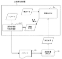
図1及び図2に示すように、本実施例のキャリブレーションシステム10は、パッチシート50を出力し、当該パッチシート50の測定結果に基づいて調整を実施する画像処理装置20と、パッチシート50を測定し、測定結果を画像処理装置20に出力する測定装置30(ここでは測色計)とを備え、これらは、USB配線や専用配線、ネットワーク配線など(ここではUSB配線40)を介して接続されている。以下、各々の装置について詳述する。 As shown in FIGS. 1 and 2, the calibration system 10 according to the present embodiment outputs a patch sheet 50, and performs adjustment based on the measurement result of the patch sheet 50, and the patch sheet 50. And a measurement device 30 (here, a colorimeter) that outputs a measurement result to the image processing device 20, which are connected via USB wiring, dedicated wiring, network wiring, etc. (here, USB wiring 40). It is connected. Hereinafter, each device will be described in detail.
[画像処理装置]
図3に示すように、画像処理装置20は、制御部21と、記憶部22と、USBI/F部23と、表示操作部24と、画像読取部25と、画像処理部26と、印刷処理部27などで構成され、これらはバスを介して接続されている。
[Image processing device]
As shown in FIG. 3, the image processing apparatus 20 includes a
制御部21は、CPU(Central Processing Unit)21a、ROM(Read Only Memory)21b、RAM(Random Access Memory)21cなどで構成される。ROM21bは、画像処理装置全体の動作を制御するためのプログラムや制御に必要なデータを記憶する。RAM21cは、CPU21aによる制御に必要なデータ及び制御動作時に一時記憶が必要なデータ等を記憶する。そして、CPU21aは、ROM21b、RAM21cと協働して画像処理装置全体の動作を制御する。
The
また、制御部21は、図4に示すように、接続検知部28と調整制御部29としても機能する。接続検知部28は、USBI/F部23にUSB接続が可能な測定装置30が接続されたことを検知する。調整制御部29は、モード設定部29aとパッチシート出力部29bと調整処理部29cなどで構成される。モード設定部29aは、接続検知部28が測定装置30の接続を検知したら、画像処理装置20の動作モードを通常モード(例えば、プリントモードなど)から調整モードに変更する。パッチシート出力部29bは、接続検知部28が検知した測定装置30に測定を実行させるための印刷物(例えば、図4に示すような各色の測定パッチ51を配列したパッチシート50など)を印刷処理部27に印刷させる。調整処理部29cは、測定装置30でパッチシート50を測定した結果を取得し、予め記憶された標準データと比較してキャリブレーションを行い、ずれを解消するための調整テーブルを生成する。
The
なお、接続検知部28及び調整制御部29はハードウェアとして構成してもよいし、コンピュータを、接続検知部28及び調整制御部29として機能させる制御プログラムとして構成し、該制御プログラムを制御部21上で動作させる構成としてもよい。
The
記憶部22は、HDD(Hard Disk Drive)などで構成される。本実施例では、印刷処理部27にパッチシート50を印刷させるための印刷データ(パッチデータと呼ぶ。)、標準データ(例えば、画像の各階調値に対して実際に出力されるべき濃度を示したデータなど)、調整テーブル(例えば、標準データで指定された濃度で印刷されるように、画像処理装置20の濃度特性に合わせて補正するため各色の濃度オフセット値を記述したテーブル)などを記憶する。 The storage unit 22 is configured by an HDD (Hard Disk Drive) or the like. In this embodiment, print data (referred to as patch data) for causing the print processing unit 27 to print the patch sheet 50, standard data (for example, the density to be actually output for each gradation value of the image). Data), an adjustment table (for example, a table describing density offset values of each color for correction according to the density characteristics of the image processing apparatus 20 so as to be printed at the density specified by the standard data), and the like. To do.
USBI/F部23は、USBポートなどで構成され、測定装置30との通信を可能とする。
The USB I / F unit 23 includes a USB port and the like, and enables communication with the
表示操作部24は、LCD(Liquid Crystal Display)などの表示部と表示部を覆うタッチパネルなどの操作部から構成され、CPU21aからの表示信号に従って、アイコンやキーボタンなどをLCD等に表示すると共に、タッチパネル等から入力される操作信号をCPU21aに出力する。なお、表示操作部24は一体的に構成してもよいし、表示部と操作部とに分離して構成してもよい。
The display operation unit 24 includes a display unit such as an LCD (Liquid Crystal Display) and an operation unit such as a touch panel that covers the display unit. The display operation unit 24 displays icons, key buttons, and the like on the LCD according to a display signal from the
画像読取部25は、原稿を走査する光源と、原稿で反射された光を電気信号に変換するCCD(Charge Coupled Devices)イメージセンサ等の各色を検出するセンサと、電気信号をA/D変換して画像データを生成するA/D変換器等により構成される。 The image reading unit 25 performs A / D conversion on a light source that scans a document, a sensor that detects each color, such as a CCD (Charge Coupled Devices) image sensor that converts light reflected by the document into an electrical signal, and the like. And an A / D converter for generating image data.
画像処理部26は、通信ネットワークに接続されたクライアントから取得した印刷データを解析し、ビットマップ形式の画像データを作成する。なお、画像処理部26の処理をネットワークに接続されるRIP(Raster Image Processor)コントローラなどで実行する構成としてもよく、その場合は、RIPコントローラで印刷データを解析し、ビットマップ形式の画像データを作成して画像処理装置20に送信すればよい。 The image processing unit 26 analyzes print data acquired from a client connected to a communication network, and creates bitmap format image data. The processing of the image processing unit 26 may be executed by a RIP (Raster Image Processor) controller or the like connected to the network. In that case, the print data is analyzed by the RIP controller and the bitmap format image data is converted. It may be created and transmitted to the image processing apparatus 20.
印刷処理部27は、画像処理部26で作成された画像データや記憶部22に予め記憶されたパッチデータに基づき電子写真プロセスに従って形成された画像を用紙に転写する。具体的には、画像データやパッチデータに基づいてレーザ光を照射して露光する書き込みユニット(図示せず)と、感光体ドラムと現像装置と帯電装置と感光体クリーニング部と1次転写ローラとを備え、イエロー(Y)、マゼンタ(M)、シアン(C)、黒(K)の各色のトナー像を形成する感光体ユニットと、ローラによって回転され、感光体ユニットで形成されたトナー像を用紙に搬送する中間転写体として機能する中間転写ベルトと、中間転写ベルト上に形成されたトナー像を用紙に転写する2次転写ローラと、用紙に転写されたトナー像を定着させる定着装置と、用紙トレイから所望の用紙を搬送する給紙ローラやレジストローラ、ループローラ、反転ローラ、排紙ローラ等の搬送部などにより構成される。 The print processing unit 27 transfers the image formed according to the electrophotographic process based on the image data created by the image processing unit 26 and the patch data stored in advance in the storage unit 22 to a sheet. More specifically, a writing unit (not shown) that irradiates and exposes laser light based on image data and patch data, a photosensitive drum, a developing device, a charging device, a photosensitive member cleaning unit, a primary transfer roller, A photosensitive unit that forms toner images of each color of yellow (Y), magenta (M), cyan (C), and black (K), and a toner image that is rotated by a roller and formed by the photosensitive unit. An intermediate transfer belt functioning as an intermediate transfer member conveyed to the paper, a secondary transfer roller for transferring the toner image formed on the intermediate transfer belt to the paper, a fixing device for fixing the toner image transferred to the paper, It is composed of a paper feed roller, a registration roller, a loop roller, a reversing roller, a paper discharge roller, and other conveyance units that convey a desired sheet from the sheet tray.
[測定装置(測色計)]
測色計30は、測色部とUSBI/F部などで構成される(図示せず)。
[Measurement device (colorimeter)]
The
測色部は、例えばRed、Green、Blueの光の3原色に対応する3種類のセンサを備え、カラー画像の各部に対する3種類のセンサからの出力値(RGB値)に基づいて測色し、測色結果を測色値としてのL*a*b*データに変換する。なお、測色計30は、刺激値直読方法を採用した色彩計でもよいし、分光測色方法を採用した分光測色計でもよい。
The color measurement unit includes, for example, three types of sensors corresponding to the three primary colors of red, green, and blue, and performs color measurement based on output values (RGB values) from the three types of sensors for each part of the color image. The color measurement result is converted into L * a * b * data as a color measurement value. The
USBI/F部は、USBポートなどで構成され、画像処理装置20との通信を可能とする。本実施例では、パッチシート50を測定した結果(測色計の場合は測色値)を画像処理装置20に送信する。 The USB I / F unit includes a USB port and the like, and enables communication with the image processing apparatus 20. In this embodiment, the result of measuring the patch sheet 50 (colorimetric value in the case of a colorimeter) is transmitted to the image processing apparatus 20.
なお、ここでは測定装置30として測色計を例にして説明したが、測定装置30は、画像処理装置20の調整を実施するために利用される測定結果を出力可能な機器であればよく、濃度情報を読み取る濃度計や位置情報を読み取るデジタイザなどとしてもよい。
Here, the color measuring device has been described as an example of the measuring
[パッチシート]
図5に示すように、パッチシート50は、Yellow、Magenta、Cyan、Blackのトナーの色毎(ここではハッチングの種類を変えて色の違いを表現している。)に、その色の濃度が所定の方向(例えば、紙送り方向又はそれに直交する方向)に沿って徐々に変化するように印刷した測定パッチ51を備える。
[Patch sheet]
As shown in FIG. 5, the patch sheet 50 has a color density for each color of Yellow, Magenta, Cyan, and Black toners (here, different types of hatching are used to express the difference in color). A measurement patch 51 printed so as to gradually change along a predetermined direction (for example, a paper feeding direction or a direction orthogonal thereto) is provided.
ここで、画像処理装置20と測定装置30とを用いてキャリブレーションを行う場合、まず、ユーザは画像処理装置20を操作してパッチシート50の出力を指示し、印刷処理部27は、記憶部22に予め記憶されたパッチデータの内、測定装置30に適したパッチデータを読み出してパッチシート50を印刷する。
Here, when performing calibration using the image processing device 20 and the
次に、ユーザは出力されたパッチシート50を測定装置30にセットし、測定装置30はパッチシート50をスキャンし、各色の測定パッチ51を測定する。そして、測定結果をユーザが画像処理装置20に入力又は送信すると、調整処理部29cは入力された測定結果と予め記憶された標準データとを比較することによって調整テーブルを作成する。
Next, the user sets the output patch sheet 50 in the
しかしながら、通常はこれら一連の動作を手動で行う必要がある。すなわち、測定装置30を画像処理装置20に接続し、画像処理装置20の動作モードを調整モードに変更し、接続した測定装置30に対応したパッチシート50の出力を指示し、測定装置30で測定した結果を画像処理装置20に取り込むなどの煩雑な作業が必要であり、測定装置30に対応していないパッチシート50を出力したり、測定結果を誤入力するなどの誤操作の原因になる。
However, it is usually necessary to perform these series of operations manually. That is, the
そこで、本実施例では、測定装置30の接続を自動認識し、画像処理装置20で簡単且つ確実に調整を実施できるようにする。すなわち、ユーザは、ただ単に測定装置30を接続するだけで、画像処理装置20の制御部21に設けた機能がその接続を判断して動作モードを調整モードに変更し、接続された測定装置30に対応するパッチシート50を出力する。また、パッチシート50の測定結果を測定装置30から取得して調整テーブルを作成する。
Therefore, in the present embodiment, the connection of the measuring
なお、画像処理装置20と測定装置30をUSBで接続する場合は、画像処理装置20の電源ONの状態で測定装置30を接続しても検知可能である。この機能はいわゆる活栓挿入やホットプラグと呼ばれ、USBコネクタの端子の内、電源ラインの2本の端子が信号線の端子よりも長くなっており、電源ラインが信号線より少し早く接触することによって実現される。また、USB配線50に代えてネットワーク配線を利用する場合は、いわゆるブロードキャストというネット上に接続している機器を検索する機能などを常時、画像処理装置20上で動作させることによって接続を検知可能である。
Note that when the image processing apparatus 20 and the
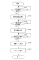
以下、図6及び図7のフローチャート図を参照して、本実施例の画像処理装置20の動作について詳細に説明する。 Hereinafter, the operation of the image processing apparatus 20 of the present embodiment will be described in detail with reference to the flowcharts of FIGS. 6 and 7.
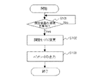
まず、図6のステップS101で、画像処理装置20の制御部21(接続検知部28)は、USBI/F部23を介して測定装置30が接続されたかを監視し、測定装置30の接続を検知したら、ステップS102で、制御部21(モード設定部29a)は、画像処理装置20の動作モードを調整モードに変更し、通常の動作モードでの処理を禁止する。
First, in step S101 of FIG. 6, the control unit 21 (connection detection unit 28) of the image processing apparatus 20 monitors whether the
次に、ステップS103で、制御部21(パッチシート出力部29b)は、記憶部22等に予め記憶されているパッチデータの内、接続された測定装置30に対応するパッチデータを読み出して印刷処理部27に転送し、印刷処理部27は、パッチデータに基づいてパッチシート50を出力する。
Next, in step S103, the control unit 21 (patch sheet output unit 29b) reads out the patch data corresponding to the connected measuring
その後、ユーザは出力されたパッチシート50を接続した測定装置30にセットし、測定装置30を操作してパッチシート50の測定を行う。そして、USB配線40を介して、その測定結果(例えば、測定パッチ51の測色値)を画像処理装置20に送信する。
Thereafter, the user sets the output patch sheet 50 to the connected measuring
画像処理装置20では、図7のステップS201で、制御部21は、測定装置30から送信される測定結果を監視し、測定結果を受信したら、ステップS202で、制御部21(調整処理部29c)は、記憶部22等に予め記憶されている標準データと受信した測定結果とを比較して補正を行い、ステップS203で、調整テーブルを作成する。
In step S201 of FIG. 7, in the image processing device 20, the
このように、接続検知部28が測定装置30の接続を検知したら、モード設定部29aは画像処理装置20の動作モードを調整モードに変更し、パッチシート出力部29bは測定装置30に対応するパッチシート50を自動的に出力するため、ユーザ自身が画像処理装置20を操作して動作モードを調整モードに変更したり、パッチシート50の出力を指示する必要がなくなり、操作性を改善し、誤操作を防止することができる。
As described above, when the
図6のフローは、画像処理装置20の電源がONの状態で測定装置30を接続(いわゆる活栓挿入)する場合であるが、画像処理装置20の電源がOFFの状態で測定装置30を接続しておくこともできる。その場合の動作を図8及び図9を参照して説明する。
The flow in FIG. 6 is for the case where the
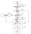
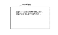
予め、画像処理装置20の電源がOFFの状態で測定装置30を接続した後、画像処理装置20を立ち上げると、図8のステップS301で、画像処理装置20の制御部21(接続検知部28)は、USBI/F部23を介して測定装置30が接続されたかを監視し、測定装置30の接続を検知したら、ステップS302で、制御部21は、動作モードを調整モードに移行可能であるかを判断する。例えば、画像処理装置20で印刷を実行するためには、印刷処理部27の各部を動作可能な状態にする(例えば、定着装置を所定の温度に加熱する)ためのウォームアップ時間が必要である。そこで、調整モードに移行可能になるまでの間は、ステップS303で、制御部21(モード設定部29a)は、表示操作部24に、例えば、図9に示すような準備画面60を表示させ、ユーザにモード変更の準備中であることを通知する。
When the image processing apparatus 20 is started up in advance after the
そして、調整モードに移行可能になったら、ステップS304で、制御部21(モード設定部29a)は、画像処理装置20の動作モードを調整モードに変更し、ステップS305で、制御部21(パッチシート出力部29b)は、接続された測定装置30に対応するパッチデータを記憶部22等から読み出して、印刷処理部27にパッチシート50を出力させる。
When it is possible to shift to the adjustment mode, in step S304, the control unit 21 (mode setting unit 29a) changes the operation mode of the image processing apparatus 20 to the adjustment mode, and in step S305, the control unit 21 (patch sheet). The output unit 29b) reads the patch data corresponding to the connected measuring
このように、画像処理装置20の電源がOFFの状態で測定装置30を接続した場合であっても、調整モードに移行可能になれば自動的に調整モードに変更されるため、ユーザの利便性を向上させることができる。
As described above, even when the
次に、本発明の第2の実施例に係る画像処理装置及び制御プログラムについて、図10及び図11を参照して説明する。図10は本実施例の画像処理装置の動作を示すフローチャート図であり、図11は画像処理装置に表示される画面の一例を示す図である。 Next, an image processing apparatus and control program according to a second embodiment of the present invention will be described with reference to FIGS. FIG. 10 is a flowchart illustrating the operation of the image processing apparatus according to the present exemplary embodiment, and FIG. 11 illustrates an example of a screen displayed on the image processing apparatus.
前記した第1の実施例では、測定装置30の接続を検知したら自動的に調整モードに変更する構成としたが、例えば、初心者などが操作している場合に調整モードに変更すると、不適切な調整を実施してしまうことも考えられる。そこで、本実施例では、モード設定部29aにユーザ認証機能を持たせて特定のユーザが使用している場合にのみ調整モードに変更可能にする。
In the first embodiment described above, when the connection of the measuring
その場合の動作を図10及び図11を参照して説明する。まず、図10のステップS401で、画像処理装置20の制御部21(接続検知部28)は、USBI/F部23を介して測定装置30が接続されたかを監視し、測定装置30の接続を検知したら、ステップS402で、制御部21(モード設定部29a)は、表示操作部24に、例えば図11(a)に示すような認証画面61を表示させ、ユーザIDやパスワードの入力を求める。
The operation in that case will be described with reference to FIGS. First, in step S401 of FIG. 10, the control unit 21 (connection detection unit 28) of the image processing apparatus 20 monitors whether the
次に、ステップS403で、制御部21(モード設定部29a)は、入力されたユーザIDやパスワードと予め記憶部22等に記憶されたユーザ情報とを比較して認証を行い、許可ユーザの場合は、ステップS404で、表示操作部24に、例えば、図11(b)に示すような許可画面62を表示させた後、ステップS406で調整モードに変更し、ステップS407でパッチシート50を出力する。一方、許可ユーザではない場合は、ステップS405で、例えば、図11(c)に示すような拒否画面63を表示させて、ユーザに調整が実施できないことを通知する。 Next, in step S403, the control unit 21 (mode setting unit 29a) performs authentication by comparing the input user ID and password with user information stored in the storage unit 22 or the like in advance. In step S404, after allowing the display / operation unit 24 to display a permission screen 62 as shown in FIG. 11B, for example, the mode is changed to the adjustment mode in step S406, and the patch sheet 50 is output in step S407. . On the other hand, if the user is not an authorized user, in step S405, for example, a rejection screen 63 as shown in FIG. 11C is displayed to notify the user that adjustment cannot be performed.
このように、特定ユーザにのみ調整モードへの変更を許可することにより、それ以外のユーザが測定装置30を接続しても調整モードに変更されないため、初心者などによる不適切な調整を未然に防ぐことができる。
In this way, by allowing only a specific user to change to the adjustment mode, even if another user connects the
次に、本発明の第3の実施例に係る画像処理装置及び制御プログラムについて、図12及び図13を参照して説明する。図12は本実施例の画像処理装置の動作を示すフローチャート図であり、図13は画像処理装置に表示される画面の一例を示す図である。 Next, an image processing apparatus and control program according to a third embodiment of the present invention will be described with reference to FIGS. FIG. 12 is a flowchart illustrating the operation of the image processing apparatus according to the present exemplary embodiment, and FIG. 13 illustrates an example of a screen displayed on the image processing apparatus.
前記した第1及び第2の実施例では、測定装置30の接続を契機として自動的に調整モードに変更することによって作業の煩雑さを軽減したが、一旦調整モードに変更された場合は、調整のための一連の作業が完了するまで、通常の動作モードでの処理は中断されてしまい、画像処理装置20を使用している他のユーザの利便性を損なう場合もある。そこで、本実施例では、モード設定部29aは、動作モードを調整モードに変更する際に、現在実行されている処理があるか、その処理の優先度は高いかなどを判断して、その結果に応じて調整モードへの移行を制限するようにする。
In the first and second embodiments described above, the complexity of work is reduced by automatically changing to the adjustment mode triggered by the connection of the measuring
その場合の動作を図12及び図13を参照して説明する。まず、図12のステップS501で、画像処理装置20の制御部21(接続検知部28)は、USBI/F部23を介して測定装置30が接続されたかを監視し、測定装置30の接続を検知したら、ステップS502で、制御部21(モード設定部29a)は、現在実行中の処理があるかを判断する。そして、現在実行中の処理がなければ、ステップS506で調整モードに変更し、ステップS507でパッチシート50を出力する。
The operation in that case will be described with reference to FIGS. First, in step S501 in FIG. 12, the control unit 21 (connection detection unit 28) of the image processing apparatus 20 monitors whether the
一方、現在実行中の処理がある場合は、ステップS503で、制御部21(モード設定部29a)は、現在実行中の処理の優先度が高いかを判断する。例えば、通常のプリントを行っている場合は、その処理を中断しても大きな問題は生じないが、特定のユーザ(特定の役職のユーザなど)がプリントを行っている場合や機密文書をプリントしている場合、画像読取部25で文書の読み取りを行っている場合には、処理が中断するとそのユーザの利便性を著しく損ねる。そこで、予め、優先度の高い処理のリストを作成して記憶部22等に記憶しておき、制御部21(モード設定部29a)は、現在実行中の処理が上記リストの処理に該当しない場合は、優先度が低い処理であると判断して、ステップS504で、表示操作部24に、例えば、図13に示すような中断通知画面64を表示させ、ユーザに現在実行中の処理が中断されたことを通知する。 On the other hand, if there is a process currently being executed, in step S503, the control unit 21 (mode setting unit 29a) determines whether the priority of the process currently being executed is high. For example, if you are doing normal printing, there will be no major problem if you interrupt the process, but if a specific user (such as a user with a specific job title) is printing or printing a confidential document. If the document is being read by the image reading unit 25, the convenience of the user is significantly impaired if the process is interrupted. Therefore, a list of high priority processes is created in advance and stored in the storage unit 22 or the like, and the control unit 21 (mode setting unit 29a) determines that the currently executing process does not correspond to the above list process. In step S504, for example, the display / operation unit 24 displays an interruption notification screen 64 as shown in FIG. 13 to interrupt the process currently being executed to the user. Notify that.
一方、現在実行中の処理が上記リストの処理に該当する場合は、制御部21(モード設定部29a)は、優先度が高い処理であると判断して、ステップS505で、現在実行中の処理の終了を監視し、現在実行中の処理が終了したら、ステップS506で調整モードに変更し、ステップS507でパッチシート50を出力する。 On the other hand, if the currently executed process corresponds to the process in the list, the control unit 21 (mode setting unit 29a) determines that the process has a high priority, and in step S505, the currently executed process. In step S506, the mode is changed to the adjustment mode, and the patch sheet 50 is output in step S507.
このように、接続検知部28が測定装置30の接続を検知しても、優先すべき処理が実行されている場合は調整モードへの移行を制限することにより、画像処理装置20を使用している他のユーザの利便性を損ねないようにすることができる。
As described above, even if the
次に、本発明の第4の実施例に係る画像処理装置及び制御プログラムについて、図14及び図15を参照して説明する。図14は本実施例の画像処理装置の動作を示すフローチャート図であり、図15は画像処理装置に表示される画面の一例を示す図である。 Next, an image processing apparatus and control program according to a fourth embodiment of the present invention will be described with reference to FIGS. FIG. 14 is a flowchart illustrating the operation of the image processing apparatus according to the present exemplary embodiment, and FIG. 15 illustrates an example of a screen displayed on the image processing apparatus.
前記した第1乃至第3の実施例では、測定装置30の接続を検知したら調整モードに変更する構成としたが、調整作業は品質保持のため一定期間(経過時間、プリント枚数)で行うことが好ましい。そこで、本実施例では、制御部21は前回調整を行ってからの経過時間やプリント枚数を監視して、適切なタイミングで調整が実施されるようにする。
In the first to third embodiments described above, the adjustment mode is changed to when the connection of the measuring
その場合の動作を図14及び図15を参照して説明する。なお、ここでは経過時間に基づいて制御するものとし、この経過時間は、画像処理装置20に設けた計時手段で計時されるものとする。 The operation in that case will be described with reference to FIGS. Here, it is assumed that the control is based on the elapsed time, and this elapsed time is measured by a timing unit provided in the image processing apparatus 20.
まず、図14のステップS601で、画像処理装置20の制御部21は、前回調整を行ってからの経過時間を監視し、経過時間が予め定めた第1の所定時間になったら、ステップS602で、表示操作部24に、例えば、図15(a)に示すような注意喚起画面65を表示させ、ユーザに調整の実施を促す。なお、図15(a)では注意喚起情報を画面全体に表示する例を示しているが、この注意喚起情報は他の作業実行中にも行うことが好ましいため、例えば、通常動作時の画面上に表示してもよい。
First, in step S601 of FIG. 14, the
次に、ステップS603で、制御部21は、注意喚起画面65を表示してから(若しくは前回調整を行ってから)の経過時間を引き続き監視し、経過時間が予め定めた第2の所定時間になったら、ステップS604で、表示操作部24に、例えば、図15(b)に示すような警告画面66を表示させると共に、画像処理装置20の印刷品質を維持するために、通常の動作モードでの処理を禁止する。
Next, in step S603, the
そして、ステップS605で、制御部21(接続検知部28)は、USBI/F部23を介して測定装置30が接続されたかを監視し、測定装置30の接続を検知したら、制御部21(モード設定部29a)は、ステップS606で調整モードに変更し、ステップS607でパッチシート50を出力する。
In step S605, the control unit 21 (connection detection unit 28) monitors whether or not the
このように、前回調整を行ってからの経過時間やプリント枚数を監視し、所定の時間が経過若しくは所定枚数のプリントを実行したら、ユーザに調整を促したり、通常の操作モードでの処理を禁止することにより、調整を適切に実施させることができる。 In this way, the elapsed time and the number of prints since the last adjustment are monitored, and when a predetermined time has passed or a predetermined number of prints have been executed, the user is prompted to make adjustments or processing in the normal operation mode is prohibited. By doing so, the adjustment can be appropriately performed.
次に、本発明の第5の実施例に係る画像処理装置及び制御プログラムについて、図16及び図17を参照して説明する。図16は本実施例の画像処理装置の動作を示すフローチャート図であり、図17は画像処理装置に表示される画面の一例を示す図である。 Next, an image processing apparatus and control program according to a fifth embodiment of the present invention will be described with reference to FIGS. FIG. 16 is a flowchart illustrating the operation of the image processing apparatus according to the present exemplary embodiment, and FIG. 17 illustrates an example of a screen displayed on the image processing apparatus.
前記した第4の実施例では、経過時間やプリント枚数に基づいて調整を促す構成としたが、あまりに短い間隔で調整を実施すると、通常の動作モードの処理が遅延したり、パッチシート50を無駄に出力することになり好ましくない。そこで、本実施例では、制御部21は前回調整を行ってからの経過時間やプリント枚数を監視して、適切なタイミングで調整が実施されるようにする。
In the fourth embodiment described above, the adjustment is urged based on the elapsed time and the number of prints. However, if the adjustment is performed at an extremely short interval, the processing in the normal operation mode is delayed or the patch sheet 50 is wasted. Is not preferable. Therefore, in this embodiment, the
その場合の動作を図16及び図17を参照して説明する。なお、本実施例でも経過時間に基づいて制御するものとし、この経過時間は、画像処理装置20に設けた計時手段で計時されるものとする。 The operation in that case will be described with reference to FIGS. In this embodiment, control is also performed based on the elapsed time, and this elapsed time is measured by a time measuring unit provided in the image processing apparatus 20.
まず、図16のステップS701で、画像処理装置20の制御部21(接続検知部28)は、USBI/F部23を介して測定装置30が接続されたかを監視し、測定装置30の接続を検知したら、ステップS702で、制御部21は、前回調整を行ってからの経過時間を取得し、経過時間が予め定めた所定時間になっていなかったら、ステップS703で、表示操作部24に、例えば、図17に示すような通知画面67を表示させ、ユーザに調整が不要であることを通知する。
First, in step S701 in FIG. 16, the control unit 21 (connection detection unit 28) of the image processing apparatus 20 monitors whether the
一方、経過時間が所定時間を超えていたら、制御部21(モード設定部29a)は、ステップS703で調整モードに変更し、ステップS704でパッチシート50を出力する。 On the other hand, if the elapsed time exceeds the predetermined time, the control unit 21 (mode setting unit 29a) changes to the adjustment mode in step S703, and outputs the patch sheet 50 in step S704.
このように、前回調整を行ってからの経過時間やプリント枚数を監視し、所定の時間が経過していない若しくは所定枚数のプリントを出力していない状態で測定装置30を接続した場合に、ユーザに調整が必要ないことを通知することにより、調整を適切に実施させることができる。
In this way, when the measuring
以上、各実施例で調整を実施する手法を説明したが、これらの調整の結果は、自動接続を契機として、すべて管理ログとして保存することも可能であり、測定装置30を特定する情報、測定結果、調整の内容、調整を実行した日時などの情報を記憶部22に保存したり、また、通信ネットワークで接続される他の機器(例えば、プリントサーバや管理装置など)に転送することも可能である。これにより、調整の偏差の経歴などが一元的に把握できるようになり、メンテナンスの指針や設計変更などの目安として使うことも可能となる。 As described above, the method of performing the adjustment in each embodiment has been described. However, the results of these adjustments can all be saved as a management log when triggered by automatic connection. As a result, information such as the contents of adjustment and the date and time of adjustment can be stored in the storage unit 22 or transferred to other devices (for example, a print server, a management device, etc.) connected via a communication network. It is. As a result, the history of adjustment deviations can be grasped in an integrated manner, and can be used as a guideline for maintenance guidelines and design changes.
また、上記各実施例では、画像形成装置20に測定装置30を接続する場合を記載したが、本発明は上記実施例に限定されるものではなく、接続する側の装置(測定装置30に相当する装置)で処理した結果を、接続される側の装置(画像形成装置20に相当する装置)で利用する任意のシステムに対して同様に適用することができる。
In each of the above embodiments, the case where the measuring
本発明は、測定装置が接続可能な画像処理装置及び当該画像処理装置で動作する制御プログラムに利用可能である。 The present invention is applicable to an image processing apparatus to which a measuring apparatus can be connected and a control program that operates on the image processing apparatus.
10 キャリブレーションシステム
20 画像処理装置
21 制御部
21a CPU
21b ROM
21c RAM
22 HDD
23 USBI/F部
24 表示操作部
25 画像読取部
26 画像処理部
27 印刷処理部
28 接続検知部
29 調整制御部
29a モード設定部
29b パッチシート出力部
29c 調整処理部
30 測定装置(測色計)
40 USB配線
50 パッチシート
51 測定パッチ
52 基準パッチ
60 準備画面
61 認証画面
62 許可画面
63 拒否画面
64 中断画面
65 注意喚起画面
66 警告画面
67 通知画面
DESCRIPTION OF SYMBOLS 10 Calibration system 20
21b ROM
21c RAM
22 HDD
23 USB I / F unit 24 Display operation unit 25 Image reading unit 26 Image processing unit 27
40 USB wiring 50 Patch sheet 51 Measurement patch 52 Reference patch 60 Preparation screen 61 Authentication screen 62 Permit screen 63 Reject screen 64 Suspend screen 65 Warning screen 66 Warning screen 67 Notification screen
Claims (16)
前記I/F部に前記測定装置が接続されたことを検知し、動作モードを前記調整モードに変更する制御部、を少なくとも備えることを特徴とする画像処理装置。 In an image processing apparatus having an I / F unit for connecting a measurement apparatus and settable in an adjustment mode in which adjustment is performed using a result measured by the measurement apparatus.
An image processing apparatus comprising: a control unit that detects that the measurement device is connected to the I / F unit and changes an operation mode to the adjustment mode.
コンピュータを、
前記I/F部に前記測定装置が接続されたことを検知し、動作モードを前記調整モードに変更する制御部、として機能させることを特徴とする制御プログラム。 A control program that operates in an image processing apparatus that has an I / F unit for connecting a measurement apparatus and that can be set in an adjustment mode in which adjustment is performed using a result measured by the measurement apparatus,
Computer
A control program that detects that the measurement device is connected to the I / F unit and functions as a control unit that changes an operation mode to the adjustment mode.
Priority Applications (2)
| Application Number | Priority Date | Filing Date | Title |
|---|---|---|---|
| JP2008261982A JP5257767B2 (en) | 2008-10-08 | 2008-10-08 | Image processing apparatus and control program |
| US12/573,388 US8570560B2 (en) | 2008-10-08 | 2009-10-05 | Image processing apparatus changing an operating mode to an adjustment mode and control program causing the same |
Applications Claiming Priority (1)
| Application Number | Priority Date | Filing Date | Title |
|---|---|---|---|
| JP2008261982A JP5257767B2 (en) | 2008-10-08 | 2008-10-08 | Image processing apparatus and control program |
Publications (2)
| Publication Number | Publication Date |
|---|---|
| JP2010093574A true JP2010093574A (en) | 2010-04-22 |
| JP5257767B2 JP5257767B2 (en) | 2013-08-07 |
Family
ID=42075574
Family Applications (1)
| Application Number | Title | Priority Date | Filing Date |
|---|---|---|---|
| JP2008261982A Expired - Fee Related JP5257767B2 (en) | 2008-10-08 | 2008-10-08 | Image processing apparatus and control program |
Country Status (2)
| Country | Link |
|---|---|
| US (1) | US8570560B2 (en) |
| JP (1) | JP5257767B2 (en) |
Families Citing this family (1)
| Publication number | Priority date | Publication date | Assignee | Title |
|---|---|---|---|---|
| JP2022175124A (en) | 2021-05-12 | 2022-11-25 | キヤノン株式会社 | Printing system, print control device and controlling method thereof, and program |
Citations (3)
| Publication number | Priority date | Publication date | Assignee | Title |
|---|---|---|---|---|
| JPH03231766A (en) * | 1990-02-07 | 1991-10-15 | Canon Inc | Electrophotographic device |
| JP2003338939A (en) * | 2002-05-20 | 2003-11-28 | Canon Inc | Apparatus, method and program for image processing |
| JP2004233707A (en) * | 2003-01-31 | 2004-08-19 | Kyocera Mita Corp | Image forming apparatus |
Family Cites Families (8)
| Publication number | Priority date | Publication date | Assignee | Title |
|---|---|---|---|---|
| US5471313A (en) * | 1993-02-24 | 1995-11-28 | Xerox Corporation | Method and control system architecture for controlling tone reproduction in a printing device |
| US5852743A (en) * | 1996-07-12 | 1998-12-22 | Twinhead International Corp. | Method and apparatus for connecting a plug-and-play peripheral device to a computer |
| US6301011B1 (en) * | 1997-11-07 | 2001-10-09 | Xerox Corporation | Dynamic plug and play interface for output device |
| ATE518199T1 (en) * | 2000-05-16 | 2011-08-15 | Arkray Inc | MEASUREMENT DATA PROCESSING SYSTEM |
| TW514786B (en) * | 2001-09-28 | 2002-12-21 | Su Fang Yu | Processing method and computer system for driver in intelligent peripherals |
| JP3951923B2 (en) * | 2003-01-29 | 2007-08-01 | コニカミノルタホールディングス株式会社 | Thermal development apparatus and thermal development method |
| JP2005027276A (en) | 2003-06-13 | 2005-01-27 | Canon Inc | Image forming method and its apparatus |
| TWI269174B (en) * | 2005-07-05 | 2006-12-21 | Istek Co Ltd | Cross-platform driver-free driving method of peripheral device |
-
2008
- 2008-10-08 JP JP2008261982A patent/JP5257767B2/en not_active Expired - Fee Related
-
2009
- 2009-10-05 US US12/573,388 patent/US8570560B2/en not_active Expired - Fee Related
Patent Citations (3)
| Publication number | Priority date | Publication date | Assignee | Title |
|---|---|---|---|---|
| JPH03231766A (en) * | 1990-02-07 | 1991-10-15 | Canon Inc | Electrophotographic device |
| JP2003338939A (en) * | 2002-05-20 | 2003-11-28 | Canon Inc | Apparatus, method and program for image processing |
| JP2004233707A (en) * | 2003-01-31 | 2004-08-19 | Kyocera Mita Corp | Image forming apparatus |
Also Published As
| Publication number | Publication date |
|---|---|
| US8570560B2 (en) | 2013-10-29 |
| JP5257767B2 (en) | 2013-08-07 |
| US20100085584A1 (en) | 2010-04-08 |
Similar Documents
| Publication | Publication Date | Title |
|---|---|---|
| JP4807886B2 (en) | Calibration system and calibration method | |
| JP4924591B2 (en) | Image forming apparatus | |
| US20110116128A1 (en) | Image forming system which includes image processing device and plural image forming devices | |
| JP4567078B2 (en) | Image forming apparatus, image forming method, printer driver program, and image forming system | |
| US9087286B2 (en) | Image formation apparatus and image formation system | |
| US20140016154A1 (en) | Service providing apparatus, service providing system, service providing method, and non-transitory computer-readable medium | |
| JP4831160B2 (en) | Image forming apparatus and image forming system | |
| US20080145087A1 (en) | Image forming apparatus and method for warming up the same | |
| US8786884B2 (en) | Printing system, printing system control method, and storage medium | |
| JP5257767B2 (en) | Image processing apparatus and control program | |
| US9207610B2 (en) | Control device, image forming apparatus, non-transitory computer readable medium, and control method | |
| JP2006163052A (en) | Image output controller | |
| EP2378368B1 (en) | Image forming system and computer program | |
| JP2006243346A (en) | Image forming apparatus | |
| JP2000103142A (en) | Print processing apparatus | |
| JP2014229064A (en) | Information processor, information processing method, information processing program, and recording medium | |
| JP4102693B2 (en) | Image forming apparatus | |
| JP2011110825A (en) | Image forming apparatus, printing system, and control program | |
| JP5623379B2 (en) | Input device and processing device | |
| US11669286B2 (en) | Method for controlling image forming system, displaying select screen, and allowing to change power modes according to instruction | |
| US20230177670A1 (en) | Information processing apparatus and method of setting inspection condition of image | |
| JP2022111569A (en) | image forming system | |
| JP2014136349A (en) | Control device and control program | |
| JP2011141326A (en) | Image forming apparatus, data processor, and image forming system with them | |
| JP2012076257A (en) | Image forming device |
Legal Events
| Date | Code | Title | Description |
|---|---|---|---|
| A621 | Written request for application examination |
Free format text: JAPANESE INTERMEDIATE CODE: A621 Effective date: 20110405 |
|
| A977 | Report on retrieval |
Free format text: JAPANESE INTERMEDIATE CODE: A971007 Effective date: 20120806 |
|
| A131 | Notification of reasons for refusal |
Free format text: JAPANESE INTERMEDIATE CODE: A131 Effective date: 20120817 |
|
| A521 | Request for written amendment filed |
Free format text: JAPANESE INTERMEDIATE CODE: A523 Effective date: 20121010 |
|
| TRDD | Decision of grant or rejection written | ||
| A01 | Written decision to grant a patent or to grant a registration (utility model) |
Free format text: JAPANESE INTERMEDIATE CODE: A01 Effective date: 20130329 |
|
| A61 | First payment of annual fees (during grant procedure) |
Free format text: JAPANESE INTERMEDIATE CODE: A61 Effective date: 20130411 |
|
| FPAY | Renewal fee payment (event date is renewal date of database) |
Free format text: PAYMENT UNTIL: 20160502 Year of fee payment: 3 |
|
| R150 | Certificate of patent or registration of utility model |
Free format text: JAPANESE INTERMEDIATE CODE: R150 |
|
| S111 | Request for change of ownership or part of ownership |
Free format text: JAPANESE INTERMEDIATE CODE: R313111 |
|
| R350 | Written notification of registration of transfer |
Free format text: JAPANESE INTERMEDIATE CODE: R350 |
|
| LAPS | Cancellation because of no payment of annual fees |