JP2010092811A - Multiple electric connector - Google Patents
Multiple electric connector Download PDFInfo
- Publication number
- JP2010092811A JP2010092811A JP2008264288A JP2008264288A JP2010092811A JP 2010092811 A JP2010092811 A JP 2010092811A JP 2008264288 A JP2008264288 A JP 2008264288A JP 2008264288 A JP2008264288 A JP 2008264288A JP 2010092811 A JP2010092811 A JP 2010092811A
- Authority
- JP
- Japan
- Prior art keywords
- plug
- connector
- fitting
- fitting connection
- electrical connector
- Prior art date
- Legal status (The legal status is an assumption and is not a legal conclusion. Google has not performed a legal analysis and makes no representation as to the accuracy of the status listed.)
- Granted
Links
Images


Landscapes
- Connector Housings Or Holding Contact Members (AREA)
- Coupling Device And Connection With Printed Circuit (AREA)
- Details Of Connecting Devices For Male And Female Coupling (AREA)
Abstract
Description
本発明は、1個の絶縁ハウジングに対して複数のプラグモジュールが接続又は離脱されるように構成された多連装電気コネクタに関する。 The present invention relates to a multiple electrical connector configured such that a plurality of plug modules are connected to or disconnected from a single insulating housing.
一般に、種々の電気機器には、一対のコネクタどうしを嵌合・抜去させるように構成された電気コネクタが広く用いられているが、そのうちの一方のコネクタに対して、適宜の信号伝送媒体が連結された複数のプラグモジュールを独立して接続又は離脱させることができるようにした多連装電気コネクタが従来から知られている(下記の特許文献1,2を参照)。そのような多連装電気コネクタにおいては、一体の絶縁ハウジングに複数の嵌合接続部が、例えば列状をなすように並設されており、それら複数の嵌合接続部のそれぞれに対して、上述した各プラグモジュールが別個に接続又は離脱されるようになっている。
In general, various electrical devices widely use an electrical connector configured to fit and remove a pair of connectors, and an appropriate signal transmission medium is connected to one of the connectors. 2. Description of the Related Art Conventionally, a multi-connection electrical connector that can connect or disconnect a plurality of plug modules independently has been known (see
このような複数のプラグモジュールを接続可能とした多連装電気コネクタは、各系統の信号伝送媒体を適宜に選択して接続させることが可能となる点において便利性を有するものであるが、当該多連装電気コネクタを他のコネクタに嵌合させたり抜去させたりする際に、複数のプラグモジュールの接続部分に変形応力が発生し易いという問題がある。特に、複数のプラグモジュールが接続状態にある多連装電気コネクタを、他のコネクタに対して同時一括的に嵌合・抜去させる場合には、プラグモジュールの接続部分をはじめとして絶縁ハウジングの全体に大きな応力が発生することから変形等を生じ易くなる。さらに、嵌合接続部の数が多い場合には、プラグモジュールの接続部分における絶縁ハウジングの肉厚が薄くなる傾向となることから絶縁ハウジング等が破損するおそれもある。 Such a multi-connector electrical connector capable of connecting a plurality of plug modules has convenience in that it is possible to appropriately select and connect signal transmission media of each system. There is a problem that deformation stress is likely to be generated in the connection portions of the plurality of plug modules when the continuous electrical connector is fitted to or removed from another connector. In particular, when multiple connected electrical connectors with multiple plug modules in a connected state are simultaneously fitted and removed from other connectors, the entire insulation housing, including the plug module connection portion, is large. Since stress is generated, deformation or the like is likely to occur. Furthermore, when the number of fitting connection portions is large, the thickness of the insulating housing at the connecting portion of the plug module tends to be reduced, and the insulating housing and the like may be damaged.
また、複数のプラグモジュールを嵌合接続部に接続するにあたっては、各プラグモジュールが独立して接続されることから接続状態が不安定になりやすいという問題があるとともに、それら複数のプラグモジュールの最終固定位置について位置ズレ等の誤差を生じていた場合には、プラグモジュールの接続によって嵌合される各種部品、例えばコンタクト(導電端子)等に不測の作用力が発生して変形や破損に至るおそれもある。 In addition, when connecting a plurality of plug modules to the fitting connection portion, each plug module is connected independently, so that there is a problem that the connection state is likely to be unstable, and the last of the plurality of plug modules is If an error such as misalignment occurs in the fixed position, unexpected action force may be generated on various parts fitted by plug module connection, such as contacts (conductive terminals), resulting in deformation or damage. There is also.
そこで本発明は、簡易な構成で、複数のプラグモジュールを有する多連装電気コネクタの嵌合・抜去を安定的に行うことができるようにして、信頼性の高い多連装電気コネクタを提供することを目的とする。 Accordingly, the present invention provides a highly reliable multi-connector electrical connector that can stably perform fitting / removal of a multi-connector electrical connector having a plurality of plug modules with a simple configuration. Objective.
上記目的を達成するため本発明にかかる電気コネクタでは、一体の絶縁ハウジングに並設された複数の嵌合接続部に対して、適宜の信号伝送媒体が連結された複数のプラグモジュールの各々が独立して接続又は離脱されるように構成されたものであって、前記複数のプラグモジュールが接続された前記絶縁ハウジングが、相手コネクタに対して嵌合又は抜去される構成になされた多連装電気コネクタにおいて、前記絶縁ハウジングに並設された嵌合接続部には、前記相手コネクタとの嵌合又は抜去に伴う付加応力に対する補強部材が付設された構成が採用されている。 In order to achieve the above object, in the electrical connector according to the present invention, each of a plurality of plug modules connected with appropriate signal transmission media is independent of a plurality of fitting connection portions arranged in parallel in an integral insulating housing. A multi-connected electrical connector configured to be connected to or disconnected from the mating connector, wherein the insulating housing to which the plurality of plug modules are connected is fitted to or removed from the mating connector. In the above, a configuration is adopted in which a fitting member provided in parallel with the insulating housing is provided with a reinforcing member against an additional stress accompanying fitting or unplugging with the mating connector.
このような構成を有する電気コネクタによれば、相手コネクタとの嵌合・抜去が行われる際に大きな応力が付加される嵌合接続部の剛性又は強度が、当該嵌合接続部に付設された補強部材により大幅に高められ、例えば複数のプラグモジュールが接続された状態でコネクタ全体が同時に一括して嵌合又は抜去されることにより高負荷が付与された場合や、嵌合接続部の数を増大させて絶縁ハウジングが薄肉状態になされている場合であっても、各嵌合接続部における剛性又は強度が補強部材により高められていることにより、絶縁ハウジング等の変形や破損が防止される。 According to the electrical connector having such a configuration, the rigidity or strength of the fitting connection portion to which a large stress is applied when fitting / removing with the mating connector is attached to the fitting connection portion. For example, when a high load is applied by simultaneously fitting or removing the entire connector in a state where a plurality of plug modules are connected, the number of fitting connection portions can be increased. Even when the insulating housing is thinned by increasing the rigidity or strength of each fitting connection portion by the reinforcing member, deformation or breakage of the insulating housing or the like can be prevented.
また、本発明にかかる電気コネクタにおける前記補強部材は、前記嵌合接続部に沿うように配置されていることが好ましい。 Moreover, it is preferable that the said reinforcement member in the electrical connector concerning this invention is arrange | positioned along the said fitting connection part.
このような構成を有する電気コネクタによれば、嵌合接続部の剛性又は強度が、当該嵌合接続部に付設された補強部材により効率的に高められる。 According to the electrical connector having such a configuration, the rigidity or strength of the fitting connection portion is efficiently enhanced by the reinforcing member attached to the fitting connection portion.
また、本発明にかかる電気コネクタにおける前記補強部材は、前記絶縁ハウジングに装着された導電性シェルの一部をなすように形成されていることが好ましい。 Moreover, it is preferable that the said reinforcement member in the electrical connector concerning this invention is formed so that a part of conductive shell with which the said insulation housing was mounted | worn may be made.
このような構成を有する電気コネクタによれば、補強部材が導電性シェルと一体的に形成されることから、補強部材の製造が容易に行われるとともに、補強部材が導電性シェルの本体部により支持されることとなって、補強部材の剛性がさらに向上されるようになっている。また、絶縁ハウジングに装着された導電性シェルが、プラグモジュールの導電性シェルとともに二重のシールドを形成する構成とすることが可能になるので、外部ノイズ等を遮断する作用(EMI)の向上が図られる。 According to the electrical connector having such a configuration, since the reinforcing member is formed integrally with the conductive shell, the manufacturing of the reinforcing member is facilitated and the reinforcing member is supported by the main body of the conductive shell. As a result, the rigidity of the reinforcing member is further improved. In addition, since the conductive shell mounted on the insulating housing can be configured to form a double shield together with the conductive shell of the plug module, the effect of blocking external noise (EMI) can be improved. Figured.
また、本発明にかかる電気コネクタでは、前記補強部材を有する導電性シェルは、前記絶縁ハウジングにインサート成形されていることが好ましい。 In the electrical connector according to the present invention, it is preferable that the conductive shell having the reinforcing member is insert-molded in the insulating housing.
このような構成を有する電気コネクタによれば、補強部材を有する導電性シェルが絶縁ハウジングに対して効率的に装着されるとともに、絶縁ハウジングの内部に補強部材が一体的に埋設されることから、比較的小さな補強部材によっても絶縁ハウジングの剛性が良好に高められる。 According to the electrical connector having such a configuration, the conductive shell having the reinforcing member is efficiently attached to the insulating housing, and the reinforcing member is integrally embedded inside the insulating housing. Even with a relatively small reinforcing member, the rigidity of the insulating housing can be improved satisfactorily.
また、本発明にかかる電気コネクタでは、前記嵌合接続部と前記プラグモジュールとを接続状態に保持する機械的固定手段が設けられ、それらの各機械的固定手段には、前記嵌合接続部の並列方向における前記プラグモジュールの最終固定位置の位置調整クリアランスが設けられていることが好ましい。 Further, in the electrical connector according to the present invention, mechanical fixing means for holding the fitting connection portion and the plug module in a connected state is provided, and each of the mechanical fixing means includes the fitting connection portion. It is preferable that a position adjustment clearance for the final fixing position of the plug module in the parallel direction is provided.
このような構成を有する電気コネクタによれば、嵌合接続部に接続されたプラグモジュールが機械的固定手段により最終固定位置に保持されるにあたって、その機械的固定手段に設けられた位置調整クリアランスの分だけ前記プラグモジュールの自由度が嵌合接続部の並列方向において確保されることとなる。従って、例えばプラグモジュールの最終固定位置についての位置ズレ誤差等を生じていた場合であっても、その位置ズレ誤差等が上述した位置調整クリアランスによって吸収されることとなり、その結果、安定した電気的接続状態が得られるようになっている。 According to the electrical connector having such a configuration, when the plug module connected to the fitting connection portion is held at the final fixing position by the mechanical fixing means, the position adjustment clearance provided in the mechanical fixing means is reduced. Accordingly, the degree of freedom of the plug module is ensured in the parallel direction of the fitting connection portion. Therefore, for example, even when a positional deviation error or the like with respect to the final fixing position of the plug module has occurred, the positional deviation error or the like is absorbed by the above-described positional adjustment clearance. Connection status can be obtained.
また、本発明にかかる電気コネクタにおける前記機械的固定手段には、前記嵌合接続部に対する前記プラグモジュールの接続又は離脱方向における最終固定位置の位置調整クリアランスが設けられていることが好ましい。 Moreover, it is preferable that the mechanical fixing means in the electrical connector according to the present invention is provided with a position adjustment clearance of a final fixing position in the connecting or detaching direction of the plug module with respect to the fitting connection portion.
このような構成を有する電気コネクタによれば、嵌合接続部に接続されたプラグモジュールが機械的固定手段により最終固定位置に保持されるにあたって、その機械的固定手段に設けられた位置調整クリアランスの分だけ前記プラグモジュールの自由度がさらに接続又は離脱方向においても確保されることとなり、さらに安定した電気的接続状態が得られるようになっている。 According to the electrical connector having such a configuration, when the plug module connected to the fitting connection portion is held at the final fixing position by the mechanical fixing means, the position adjustment clearance provided in the mechanical fixing means is reduced. Accordingly, the degree of freedom of the plug module is further secured in the connecting or disconnecting direction, and a more stable electrical connection state can be obtained.
また、本発明にかかる電気コネクタにおける前記機械的固定手段は、前記嵌合接続部の並列方向と前記プラグモジュールの前記嵌合接続部に対する接続方向との双方を含む平面と直交する方向における前記プラグモジュールの最終固定位置を、位置調整クリアランスを介在することなく位置決め規制する構成になされていることが好ましい。 In the electrical connector according to the present invention, the mechanical fixing means includes the plug in a direction orthogonal to a plane including both a parallel direction of the fitting connection portion and a connection direction of the plug module to the fitting connection portion. It is preferable that the final fixing position of the module is configured to restrict positioning without interposing a position adjustment clearance.
このような構成を有する電気コネクタによれば、嵌合接続部に接続されたプラグモジュールが機械的固定手段により最終固定位置に保持されるにあたって、嵌合接続部の並列方向及びプラグモジュールの接続方向の双方を含む平面に直交する方向、すなわち電気的な接触性には直接的な関係を有しない方向においては、プラグモジュールが安定的に位置規制されながら案内されることとなり、プラグモジュールの接続又は離脱の操作が良好に行われるようになっている。 According to the electrical connector having such a configuration, when the plug module connected to the fitting connection portion is held at the final fixing position by the mechanical fixing means, the parallel direction of the fitting connection portion and the connection direction of the plug module In a direction perpendicular to the plane including both of the above, that is, a direction that does not have a direct relationship with the electrical contact property, the plug module is guided while being stably positioned. The detachment operation is performed well.
また、本発明にかかる電気コネクタにおける前記機械的固定手段は、前記嵌合接続部を有する絶縁ハウジングに形成された平面略矩形状の係止穴部と、前記プラグモジュールに設けられて前記係止穴部に嵌合される係合突起部とから構成され、前記係合突起部は、前記プラグモジュールの前記嵌合接続部に対する接続方向に向かって頂部を有する平面略三角形状に形成されていることが好ましい。 Further, the mechanical fixing means in the electrical connector according to the present invention includes a planar substantially rectangular locking hole formed in an insulating housing having the fitting connection portion, and the locking module provided in the plug module. The engaging protrusion is fitted in the hole, and the engaging protrusion is formed in a substantially triangular shape having a top portion in the connecting direction of the plug module with respect to the fitting connection portion. It is preferable.
このような構成を有する電気コネクタによれば、プラグモジュールの接続時に、係止穴部に対して係合突起部の頂部、つまり尖塔状の先端部分から円滑に挿入されていくとともに、平面略三角形状の底辺を形成する底辺部が係止穴部に対して確実に係止されることとなって安定した嵌合状態が得られるようになっている。 According to the electrical connector having such a configuration, when the plug module is connected, it is smoothly inserted into the locking hole from the top of the engaging projection, that is, the tip of the spire, and the plane is substantially triangular. The bottom part forming the bottom of the shape is securely locked to the locking hole, so that a stable fitting state can be obtained.
また、本発明にかかる電気コネクタにおける前記機械的固定手段は、前記一個の嵌合接続部につき複数設けられていることが好ましい。 Moreover, it is preferable that a plurality of the mechanical fixing means in the electrical connector according to the present invention is provided for the one fitting connection portion.
このような構成を有する電気コネクタによれば、一箇所の嵌合接続部に接続されたプラグモジュールが、複数箇所にわたって係止されることから、プラグモジュールの特に回転方向の移動が良好に防止されることとなり、その結果、安定した嵌合状態が得られるようになっている。 According to the electrical connector having such a configuration, since the plug module connected to one fitting connection portion is locked at a plurality of locations, the movement of the plug module, particularly in the rotation direction, is well prevented. As a result, a stable fitting state can be obtained.
以上述べたように本発明にかかる電気コネクタは、複数のプラグモジュールがそれぞれ接続又は離脱されるように絶縁ハウジングに並設された複数の嵌合接続部の各々に、相手コネクタとの嵌合又は抜去に伴う付加応力に対する補強部材を付設し、相手コネクタとの嵌合・抜去が行われる際に大きな応力が付加される嵌合接続部の剛性又は強度を大幅に高め、複数のプラグモジュールが接続された状態でコネクタ全体が同時に嵌合・抜去されることにより高負荷が付与された場合や、嵌合接続部の数を増大させて絶縁ハウジングが薄肉状態になされている場合であっても、絶縁ハウジング等の変形や破損を防止するように構成したものであるから、簡易な構成で、複数のプラグモジュールを有する多連装電気コネクタの嵌合・抜去を安定的に行うことができ、多連装電気コネクタの信頼性を安価かつ大幅に高めることができる。 As described above, the electrical connector according to the present invention can be fitted or mated with the mating connector in each of the plurality of fitting connection portions arranged in parallel in the insulating housing so that the plurality of plug modules are connected or disconnected, respectively. A reinforcement member is added to the additional stress accompanying removal, and the rigidity or strength of the mating connection part to which large stress is applied when mating / unmating with the mating connector is greatly increased, and multiple plug modules are connected. Even when a high load is applied by fitting and removing the entire connector at the same time, or when the insulation housing is made thin by increasing the number of fitting connection parts, Since it is configured to prevent deformation and breakage of the insulating housing, etc., it is possible to stably connect and disconnect multiple connected electrical connectors having multiple plug modules with a simple configuration. Ukoto can, it is possible to enhance the reliability of Tarenso electrical connector inexpensive and significantly.
以下、信号伝送媒体として同軸ケーブルを用いたプラグコネクタに本発明を適用した場合における実施の形態を図面に基づいて詳細に説明する。 Hereinafter, embodiments in the case where the present invention is applied to a plug connector using a coaxial cable as a signal transmission medium will be described in detail with reference to the drawings.
[コネクタ組立体の全体構造について]
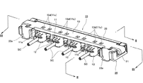
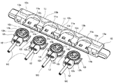
まず、図1〜図3に表された本発明の一実施形態にかかる電気コネクタの組立体は、複数本(4本)の信号伝送媒体としての同軸ケーブルSCの端末部分が連結されたプラグコネクタ(本発明にかかる多連装電気コネクタ)10と、図示を省略した印刷配線基板上に実装されるリセプタクルコネクタ20とからなる垂直嵌合型コネクタを構成している。この電気コネクタの組立体を構成しているプラグコネクタ10及びリセプタクルコネクタ20は、前記同軸ケーブルSCの配列方向に沿って細長状に延在する形状を有しており、例えば図4に示されているように、印刷配線基板(図示省略)上に実装されたリセプタクルコネクタ20の直上位置にプラグコネクタ10が略平行に配置された状態で、印刷配線基板と略直交する図示下方側に向かって前記プラグコネクタ10が下降されて、前記リセプタクルコネクタ20の嵌合部分にプラグコネクタ10の嵌合部分が差し込まれることにより、それら両コネクタ10,20どうしが図1〜図3のように嵌合される構成になされている。以下、プラグコネクタ10を差し込む嵌合方向を下方向とし、それとは反対の抜き出す抜去方向を上方向とする。
[Overall structure of connector assembly]
First, an assembly of an electrical connector according to an embodiment of the present invention shown in FIGS. 1 to 3 is a plug connector in which terminal portions of coaxial cables SC as a plurality (four) of signal transmission media are connected. (Vertical fitting connector) comprising (multi-connecting electrical connector according to the present invention) 10 and a
[プラグコネクタ(多連装電気コネクタ)について]
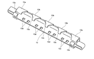
ここで、前記プラグコネクタ10は、本発明にかかる多連装電気コネクタを構成するものであるが、図5〜図8にも示されているように、上述した同軸ケーブルSCの配列方向に沿って細長状に延在する絶縁部材からなるプラグハウジング(絶縁ハウジング)11を有している。そして、そのプラグハウジング11の長尺状に延在する端面部分に、前記同軸ケーブルSCがそれぞれ連結された複数体(4体)のプラグモジュール12〜12が、それぞれ独立して接続又は離脱される構成になされている。以下、上記プラグハウジング11において、プラグモジュール12が嵌合される側を後端側(図5の右側)とし、それとは反対側を前端側(図5の左側)とする。
[About plug connectors (multiple electrical connectors)]
Here, although the said
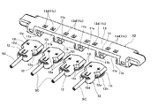
前記プラグハウジング(絶縁ハウジング)11には、当該プラグハウジング11の後端面に開口部を有する複数体(4体)の嵌合接続部11a〜11aが、長手方向に沿って列状に並設されるように設けられている(特に図7及び図8参照)。それらの各嵌合接続部11aは、平面略半円状の環状壁面により仕切られた凹状空間を備えていて、当該各嵌合接続部11aの後端側の開口部から内部の環状空間に向かって、上述したプラグモジュール12のそれぞれが独立して挿入されるようになっている。
In the plug housing (insulating housing) 11, a plurality (four bodies) of
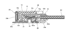
また、前記プラグハウジング(絶縁ハウジング)11には、特に図9に示されているような導電性シェル13が例えばインサート成形又は圧入により装着されている。その導電性シェル13は、薄板状の金属部材を適宜の形状をなすように折り曲げ成形したものであって、前記プラグハウジング11の前端面側部分、平面側部分、及び長手方向の両側部分においてほぼ全面を外方側から覆うように配置されている。また、当該導電性シェル13は、前記プラグハウジング11の底面側部分に対して、上述した嵌合接続部11a〜11aを除いた領域を外方側から覆うように形成されている。このような導電性シェル13の各部は、後述するようにリセプタクルコネクタ20側の導電性シェル23に対して電気的に接触される構成になされている。
In addition, a
上述したように導電性シェル13は、前記プラグハウジング(絶縁ハウジング)11の底面側部分の一部を覆うように形成されているが、より具体的には、当該導電性シェル13の底面側部分は、前方側下端縁から底面後方側に向かって延出しており、上述した嵌合接続部11a〜11aを回避するように傾斜辺を有している。すなわち、この導電性シェル13の長手方向の両端部分には、平面略台形状をなす一対の外側補強部材13a,13aが配置されているとともに、これら一対の外側補強部材13a,13aの間部分には、平面略三角形状をなす3体の内側補強部材13b,13b,13bが配置されている。
As described above, the
これらの外側補強部材13a,13a及び内側補強部材13b,13b,13bは、前記導電性シェル13の長手方向に沿って列状に並設されるように配置されており、その配列の両側に配置された一対の外側補強部材13a,13aは、上述したプラグハウジング(絶縁ハウジング)11の両端位置に配置された両嵌合接続部11aの外方側に配置されている。また、前記内側補強部材13b,13b,13bは、前記プラグハウジング11の長手方向に隣接する嵌合接続部11a,11aどうしの間部分に配置されており、各嵌合接続部11aを両側から挟む配置関係になされている。
These outer reinforcing
このように配置された外側補強部材13a及び内側補強部材13bの各々は、前記導電性シェル13の前方側下端縁から比較的幅広状をなすようにして後方側(図6の右方側)に向かって延出した後に、上述した各嵌合接続部11aの外径に沿って傾斜辺状をなすように延在している。これら外側補強部材13a及び内側補強部材13bの後方側延出端部分(図6の右端部分)は、上述した各嵌合接続部11aの最大外径部分の近傍に位置している。
Each of the outer reinforcing
そして、前記外側補強部材13a及び内側補強部材13bのそれぞれにおける後端部分(図6の右端部分)には、側面略L字状をなして立ち上がるように折り曲げ成形されたフック状埋設片13cが設けられており、それらの各フック状埋設片13cが、前記プラグハウジング(絶縁ハウジング)11の内部側に向かって所定量だけ突出するように配置されている。このような配置関係でインサート成形又は圧入された前記導電性シェル13の外側補強部材13a及び内側補強部材13bが装着されていることによって、上述した各嵌合接続部11aの周囲、及びプラグハウジング(絶縁ハウジング)11の全体の強度が、大幅に向上されている。
A hook-like embedded
また、上述したように嵌合接続部11a〜11aは、前記プラグハウジング(絶縁ハウジング)11の後端面にプラグモジュール12を挿入させるための正面略矩形状の開口部を備えているが、それらの各開口部は下方に向かって開放された形状になされている。すなわち、前記嵌合接続部11aを形成している開口縁部のうちの下縁に相当する部位は、中央部分が開放された状態になされており、前記開口部の両側部分に設けられた一対の案内突起11b,11bによって一部のみが形成されている(特に図7及び図8参照)。それら一対の案内突起11b,11bは、前記開口部の両側から内方に向かって適宜の突出量だけ対向するように張り出しており、前記開口部から挿入されたプラグモジュール12を、下方側から保持しつつ案内する機能を有している。これに対して、前記嵌合接続部11aの開口縁部のうちの上縁に相当する部位は、プラグハウジング11の上側壁部(平面側壁部)が前記開口部の全長にわたって略直線状をなすように延在している。
Further, as described above, the
さらにまた、前記プラグハウジング(絶縁ハウジング)11の上側壁部(平面側壁部)には、上述した嵌合接続部11aごとに、機械的固定手段としての一対の係止穴部11c,11cがそれぞれ形成されている。これらの各係止穴部11cは、平面略矩形状をなすように形成されており、前記導電性シェル13の上側壁部の同位置に、同じく機械的固定手段として形成された一対の係止穴部13d,13dと連通するように配置されている。これらの各係止穴部11c,13dには、後述するプラグモジュール12側に設けられた係合突起部12aが嵌合される構成になされているが、これらプラグコネクタ10側の係止穴部11c,13dと、プラグモジュール12側の係合突起部12aとの間には、最終固定位置の自由度を確保する位置調整クリアランスCx,Cyが設けられている。その点ついては後段において詳細に説明することとする。
Furthermore, a pair of locking
[プラグモジュールについて]
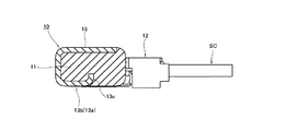
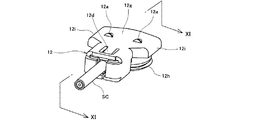
一方、上述したプラグモジュール12は、特に図10〜図12に示されているように当該プラグモジュール12の後端部分に対して、信号伝送媒体としての同軸ケーブルSCの端末部分が連結されている。以下において、上記同軸ケーブルSCが連結される側の端部を後端部と呼び、それとは反対側の他端部を前端部と呼ぶこととする。また、このプラグモジュール12が、前述したプラグハウジング11の嵌合接続部11aに挿入(嵌合)される方向を前方とし、その反対に抜去される方向を後方とする。
[About plug modules]
On the other hand, in the
プラグモジュール12に連結された各同軸ケーブル(信号伝送媒体)SCの端末部分は、被覆材が皮剥きされることによって、ケーブル中心導体(信号線)SCa及びケーブル外部導体(シールド線)SCbが同軸状をなすように露出されている。そして、その同軸ケーブルSCの中心軸線に沿うようにして配置されたケーブル中心導体SCaが前記プラグモジュール12のモジュールハウジング12bの内部に装着された信号伝送用の導電コンタクト(導電端子)12cに接続され、それによって信号回路が構成されるようになっている。
The terminal portion of each coaxial cable (signal transmission medium) SC connected to the
上述した導電コンタクト(導電端子)12cは、前記ケーブル中心導体SCaとの接続部分から前方側(図2の左方側)に向かって略水平に延在しており、その延在部分における途中位置に、前述したリセプタクルコネクタ20側に接触する接点部が設けられている。その導電コンタクト12cの接点部は、前記モジュールハウジング12bに設けられている中空状の環状嵌合部の略中心位置に配置されるように形成されていて、前述したプラグコネクタ10がリセプタクルコネクタ20に嵌合された際に、リセプタクルコネクタ20側の接点部と接触して電気的な接続が行われるようになっている。
The conductive contact (conductive terminal) 12c described above extends substantially horizontally from the connecting portion with the cable center conductor SCa toward the front side (the left side in FIG. 2), and the intermediate position in the extending portion. Further, a contact portion that contacts the above-described
また、前記導電コンタクト12cの延在方向における先端部分は、略Uの字状をなして反対方向に反転するように折り曲げ形成されており、その反転部分の途中位置に形成された凹状曲げ部の弾性力によって、上述したケーブル中心導体(信号線)SCaが挟持される構成になされている。
The leading end portion in the extending direction of the
さらに、前述したケーブル中心導体SCaの外周側を取り囲むように配置されたケーブル外部導体SCbは、グランド部材を構成している上部グランドバー12eと下部グランドバー12fとの間において上下に挟持されるように配置されており、半田付けやカシメや圧接等により接続されている。そして、これらの両グランドバー12e,12fが、前述した導電性シェル13等を介してグランド接続されることによりグランド回路が構成されるようになっている。
Further, the cable outer conductor SCb disposed so as to surround the outer peripheral side of the cable center conductor SCa described above is sandwiched vertically between the
さらにまた、前記モジュールハウジング12bには、導電性シェル12gが例えばインサート成形又は圧入により装着されている。この導電性シェル12gは、薄板状の金属部材を適宜の形状をなすように折り曲げ成形したものであって、前記モジュールハウジング12bの環状嵌合部の下端側開口部を除いたほぼ全面を外方側から覆うように形成されている。この導電性シェル12gの後端部分(図11の右端部分)には、舌片状をなすように切欠き形成されたグランド接続片12dが斜め下方に延出するように設けられており、その接続片12dの延出側の先端部分が、上述した上部グランドバー12eに圧接されていることによってグランド接続が行われている。
Furthermore, a
このような導電性シェル12gには、上述した導電コンタクト12cを環状に取り囲むようにして略中空円筒状のグランドコンタクト12hが一体的に設けられている。このグランドコンタクト12hは、前記モジュールハウジング12bの環状嵌合部の外周に沿って装着されており、前記プラグコネクタ10がリセプタクルコネクタ20に嵌合された際に、リセプタクルコネクタ20側のグランドコンタクト22と接触して電気的な接続が行われることによってグランド回路を構成する機能を有している。
The
また、前記導電性シェル12gの両側部分、すなわち前述したプラグコネクタ10の長手方向における両端部分には、一対のガイド部12i,12iが外方に張り出すように設けられている。これらのガイド部12i,12iは、上述した嵌合接続部11aに対するプラグモジュール12の接続・離脱方向(前後方向)に沿って細長状に延在するレール状部材から形成されており、前記プラグコネクタ10に設けられた嵌合接続部11aの開口部両側部分に沿って挿入される構成になされている。より具体的には、上述したように嵌合接続部11aの開口部の両側部分に設けられた案内突起11b,11bに対して、前記ガイド部12i,12iが摺接しながら相対移動することによって、プラグモジュール12の接続・離脱を円滑に案内する構成になされている。
A pair of
さらに、前述したように導電性シェル12gの上面部分には、一対の係合突起部12a,12aが設けられている。それら一対の係合突起部12a,12aは、プラグモジュール12がプラグコネクタ10側に挿入された際における機械的固定手段を構成するものであって、当該プラグモジュール12bの挿入方向(図11の左方向)に向かって尖塔状をなす平面略三角形状に形成されている。これら一対の係合突起部12a,12aは、前述したプラグコネクタ10のプラグハウジング11及び導電性シェル13の上側壁部(平面側壁部)に、同じく機械的固定手段として貫通形成された係止穴部11c,11cの内部にそれぞれ嵌合される構成になされている。
Furthermore, as described above, the pair of engaging
このようにプラグモジュール12がプラグコネクタ10側に挿入されて、プラグコネクタ10側の係止穴部11c,13dの内部にプラグモジュール12側の係合突起部12aが嵌合された際には、特に図13に示されているように、前記プラグコネクタ10側の係止穴部11c,13dと、プラグモジュール12側の係合突起部12aとの間に、最終固定位置の自由度を確保するための位置調整クリアランスCx,Cyが形成されるようになっている。それら両位置調整クリアランスのうちの一方の位置調整クリアランスCyは、図13中の左右方向であるコネクタ長手方向、すなわち前記嵌合接続部11a〜11aの並列方向(Y方向)における適宜の隙間から形成されているとともに、他方の位置調整クリアランスCxは、図13中の上下方向、すなわちプラグモジュール12の接続又は離脱方向(X方向)における適宜の隙間から形成されている。
Thus, when the
上述したように本実施形態における機械的固定手段11c,13d及び12aでは、プラグコネクタ10に対するプラグモジュール12の最終固定位置の自由度を確保するための位置調整クリアランスCx,Cyが設けられており、それら位置調整クリアランスCx,Cyの分だけプラグモジュール12が最終的に多少の移動が可能となっている。その結果、例えば両者(プラグコネクタ10及びリセプタクルコネクタ20)の接点部どうしの間に位置ズレ誤差等が生じていても、その位置ズレ誤差を吸収するようにプラグハウジング11に対してプラグモジュール12が相対的に位置移動することとなり、良好な電気的接触状態が安定的に得られる。
As described above, in the mechanical fixing means 11c, 13d and 12a in the present embodiment, the position adjustment clearances Cx and Cy for ensuring the degree of freedom of the final fixing position of the
なお、上述したX方向及びY方向と直交するZ方向、すなわち前記嵌合接続部11aの並列方向と、前記嵌合接続部11aに対するプラグモジュール12の接続又は離脱方向との双方を含む平面に直交する上下方向(高さ方向)においては、プラグハウジング11に対してプラグモジュール12が相対的に位置移動することを可能とする最小の摺動用クリアランスのみを有しており、前述したX方向及びY方向のような位置調整クリアランスを介在することなくプラグモジュール12の最終固定位置を規制する構成になされている。より具体的には、上述したガイド部12iにおける上下方向(Z方向)の高さ寸法が、前記プラグハウジング11の上側壁部と案内突起11bとの間の距離とほぼ同じ寸法となるように構成されており、それによって前記プラグモジュール12が上下方向(Z方向)に位置決めされつつ嵌合接続部11aの内部に挿入されていき、最終固定位置にて係合突起部12aが係止穴部11c,13dに嵌合されるようになっている。
It should be noted that the Z direction perpendicular to the X direction and Y direction described above, that is, the plane including both the parallel direction of the
[リセプタクルコネクタについて]
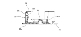
一方、前記プラグコネクタ(本発明にかかる多連装電気コネクタ)10が嵌合されるリセプタクルコネクタ20は、特に図14及び図15に示されているように、前述したプラグハウジング11と同様な細長状のリセプタクルハウジング21を備えている。そのリセプタクルハウジング21の底面部には、長手方向に沿って複数体(4体)の導電コンタクト(導電端子)22〜22が、例えば圧入又はインサート成形により取り付けられている。これらの各導電コンタクト22は、前述したプラグモジュール12に対応して配置された略円柱状部材から構成されており、前記リセプタクルハウジング21の底面部から上方に向かって突出するように設けられている。
[Receptacle connector]
On the other hand, a
この略円柱状をなす導電コンタクト(導電端子)22の上端部分には接点部が形成されていて、前記リセプタクルコネクタ20にプラグコネクタ10が上方側から嵌合された際に、当該導電コンタクト22の上端接点部に対して、前述したプラグモジュール12に設けられた導電コンタクト12cの接点部が上方側から圧接するように接触して電気的な接続が行われるようになっている(特に図2参照)。
A contact portion is formed at the upper end portion of the substantially cylindrical conductive contact (conductive terminal) 22, and when the
上述した各導電コンタクト22の下端部分は、前記リセプタクルハウジング21の底面側表面に沿って前方側(図2の左方側)に延出する半田接続部22aになされており、その導電コンタクト22の半田接続部22aが、図示を省略した印刷配線基板上の導電路に半田付けされて実装が行われるようになっている。
The lower end portion of each
さらに、前記リセプタクルハウジング21の底面部には、前記導電コンタクト(導電端子)22を同心状に取り囲むようにして略中空円筒状のグランドコンタクト22bがインサート成形等により取り付けられている。このグランドコンタクト22bは、前述したプラグコネクタ10側のグランドコンタクト12hに対応して複数体(4体)のものが配置されており、プラグコネクタ10がリセプタクルコネクタ20に嵌合された際に、それら両グランドコンタクト12h,22bが接触されてグランド回路が形成されるようになっている。
Further, a substantially hollow
また、上述したリセプタクルコネクタ20側の各グランドコンタクト22bは、前記リセプタクルハウジング21の底面側表面に沿って後方側に延出して3つの半田接続部22c,22c,22cに分岐されている。それらの半田接続部22c,22c,22cは、コネクタ長手方向(図15の紙面垂直方向)に適宜の間隔で並列するように配置されており、図示を省略した印刷配線基板上の導電路に半田付けされて実装が行われるようになっている。
Each of the
この各グランドコンタクト22bごとに設けられた3つの半田接続部22c,22c,22cのうちの両側に位置する一対の半田接続部22c,22cは、上述したリセプタクルハウジング21の底面部に設けられた切欠部21aの辺部に沿って延在するように設けられている。すなわち、互いに隣接するグランドコンタクト22bにおける両側一対の半田接続部22c,22cどうしの間部分には、前記リセプタクルハウジング21の底面部に平面略矩形状の切欠部21aがそれぞれ設けられており、その切欠部21aの両側辺部に沿って前記両側の半田接続部22c,22cが長尺状をなすように設けられている。このように両側一対の半田接続部22c,22cが長尺状に配置されていることによって、当該半田接続部22cの電気抵抗が減じられるとともに、前記切欠部21aの内方側の空間が半田材の溜り領域に確保されることから、半田接続が容易かつ良好に行われるようになっている。また、半田接続領域が増えたことで、図示しない印刷配線基板に強固に接続されるようになっている。
A pair of
さらに、上述したリセプタクルハウジング21の前端側立壁部から長手方向両端部分にかけての部位は、導電性シェル23により覆われている。この導電性シェル23は、薄板状の金属部材から形成されており、前述したプラグコネクタ10がリセプタクルコネクタ20に嵌合された際に、プラグコネクタ10側の導電性シェル13と接触することによってグランド回路を構成する機能を有している。
Further, a portion from the front end side standing wall portion of the
この導電性シェル23の一部は、上述した印刷配線基板上の導電路に半田付けされるホ−ルドダウン23aをなすように形成されており、当該ホ−ルドダウン23aによってグランド回路が形成されるとともに、リセプタクルコネクタ20全体が強固に保持されるようになっている。このホールドダウン23aは、リセプタクルコネクタ20全体の概略四隅に位置するように形成されていている。
A part of the
さらに、上述した導電性シェル23の前端側部分(図15の左端側部分)には、コネクタ長手方向(図15の紙面垂直方向)沿って延在する前端側立壁部23bが設けられていいるとともに、その前端側立壁部23bの内壁面に、上下方向(高さ方向)に延在する接触バネ部23cが、切り起こし形状をなすようにして形成されている。この接触バネ部23cは、コネクタ長手方向(図15の紙面垂直方向)に所定の間隔をなして複数のものが設けられており、前記プラグハウジング11の嵌合が行われた際に、上述したプラグコネクタ10の導電性シェル13が上記接触バネ部23cに接触して電気的な接続が行われるようになっている。
Further, the front end side portion (the left end side portion in FIG. 15) of the
このような構成を有する本実施形態によれば、両コネクタ10,20どうしの嵌合・抜去が行われる際に大きな応力が付加されるプラグコネクタ10の嵌合接続部11aにおける剛性又は強度が、当該嵌合接続部11aに付設された補強部材13a,13bにより大幅に高められる。例えば、複数のプラグモジュール12が接続された状態でプラグコネクタ10の全体が同時に一括して嵌合又は抜去されることにより高負荷が付与された場合や、嵌合接続部11aの数を増大させてプラグハウジング(絶縁ハウジング)11が薄肉状態になされている場合であっても、各嵌合接続部11aにおける剛性又は強度が補強部材13a,13bにより高められていることにより、プラグハウジング11等の変形や破損が防止される。
According to the present embodiment having such a configuration, the rigidity or strength of the
特に本実施形態では、補強部材13a,13bが、嵌合接続部11aに沿うように配置されていることから、嵌合接続部11aの剛性又は強度が効率的に高められるようになっている。
In particular, in this embodiment, since the reinforcing
また本実施形態においては、補強部材13a,13bが、プラグハウジング11に装着された導電性シェル13の一部をなすように形成されていることから、補強部材13a,13bが導電性シェル13と一体的に形成されることとなって当該補強部材13a,13bの製造が容易に行われるとともに、補強部材13a,13bが導電性シェル13の本体部により支持されることから剛性がさらに向上されるようになっている。
In the present embodiment, since the reinforcing
またこのとき、プラグハウジング(絶縁ハウジング)11に装着された導電性シェル13が、プラグモジュール12の導電性シェル12gとともに二重のシールドを形成していることから、外部ノイズ等を遮断する性能(EMI)の向上が図られている。
At this time, since the
さらに本実施形態においては、前記補強部材13a,13bを有する導電性シェル13は、前記プラグハウジング11にインサート成形されていることから、補強部材13a,13bを有する導電性シェル13がプラグハウジング11に対して効率的に装着されるとともに、プラグハウジング11の内部に補強部材13a,13bが一体的に埋設され、比較的小さな補強部材13a,13bによってもプラグハウジング11の剛性が良好に高められる。
Furthermore, in this embodiment, since the
さらにまた本実施形態においては、プラグモジュール12を嵌合状態に保持する機械的固定手段11c,13d及び12aに、嵌合接続部11aの並列方向における最終固定位置の位置調整クリアランスCy及びプラグモジュール12の嵌合接続部11aに対するて接続又は離脱方向における最終固定位置の位置調整クリアランスCxが設けられていることから、その位置調整クリアランスCy,Cxの分だけ前記プラグモジュール12の自由度が確保されることとなる。従って、例えばプラグモジュール12の最終固定位置についての位置ズレ誤差等を生じていた場合であっても、その位置ズレ誤差等が上述した位置調整クリアランスCy,Cxによって吸収されることとなり、その結果、安定した電気的接続状態が得られるようになっている。
Furthermore, in the present embodiment, the mechanical fixing means 11c, 13d and 12a for holding the
このとき、上記プラグモジュール12の機械的固定手段11c,13d及び12aは、嵌合接続部11aの並列方向及び前記プラグモジュール12の嵌合接続部11aに対する接続又は離脱方向の双方を含む平面と直交する上下方向における最終固定位置を、位置調整クリアランスを介在することなく規制する構成になされていることから、プラグモジュール12が安定的に保持されることなって当該プラグモジュール12の接続又は離脱の操作が良好に行われるようになっている。
At this time, the mechanical fixing means 11c, 13d, and 12a of the
また本実施形態では、嵌合接続部11aに対するプラグモジュール12の接続時に、プラグコネクタ10の係止穴部11cに対して係合突起部12aの頂部、つまり尖塔状の先端部分から円滑に挿入されていくとともに、当該係合突起部12aの平面略三角形状の底辺を形成する底辺部が係止穴部11c,13dに対して確実に係止され、安定した嵌合状態が得られるようになっている。
Further, in the present embodiment, when the
さらに本実施形態では、プラグモジュール12の機械的固定手段11c,13d及び12aが、一個の嵌合接続部11aにつき2箇所設けられていることから、一箇所の嵌合接続部11aに接続されたプラグモジュール12が二箇所にわたって係止され、プラグモジュール12の、特に回転移動が良好に防止されることとなって安定した嵌合状態が得られるようになっている。
Furthermore, in this embodiment, since the mechanical fixing means 11c, 13d, and 12a of the
以上、本発明者によってなされた発明を実施形態に基づき具体的に説明したが、本発明は上述した実施形態に限定されるものではなく、その要旨を逸脱しない範囲で種々変形可能であるというのはいうまでもない。 Although the invention made by the present inventor has been specifically described based on the embodiments, the present invention is not limited to the above-described embodiments, and various modifications can be made without departing from the scope of the invention. Needless to say.
例えば上述した実施形態は、プラグモジュール12の数が4個の場合のものであるが、プラグモジュール12の数が4個以上又は以下のいずれの場合であっても、本発明は同様に適用することができる。
For example, the embodiment described above is for the case where the number of
また、上述した実施形態は、垂直嵌合型の電気コネクタに本発明を適用したものであるが、水平嵌合型の電気コネクタに対しても同様に適用することができ、さらに本発明を適用したプラグコネクタ以外の、例えばリセプタクルコネクタ等に対しても本発明は同様に適用することができる。 Moreover, although the above-described embodiment is an application of the present invention to a vertical fitting type electrical connector, it can be similarly applied to a horizontal fitting type electrical connector, and the present invention is further applied. The present invention can be similarly applied to, for example, a receptacle connector other than the plug connector.
さらにまた本発明は、上述した各実施形態のような同軸ケーブル用コネクタに限定されることはなく、絶縁ケーブル用コネクタや、同軸ケーブルと絶縁ケーブルとが複数混合したタイプの電気コネクタや、フレキシブル配線基板等が連結される電気コネクタ、プリント基板同士を接続する基板対基板コネクタ等についても同様に適用することが可能である。 Furthermore, the present invention is not limited to the coaxial cable connector as in each of the above-described embodiments, but includes an insulated cable connector, a type of electrical connector in which a plurality of coaxial cables and insulated cables are mixed, and flexible wiring. The present invention can be similarly applied to an electrical connector to which a board or the like is connected, a board-to-board connector for connecting printed boards to each other, and the like.
以上のように本実施形態は、各種電気機器に使用される多種多様な多連装電気コネクタに対して広く適用することが可能である。 As described above, the present embodiment can be widely applied to a wide variety of multiple electrical connectors used in various electrical devices.
10 プラグコネクタ(多連装電気コネクタ)
20 リセプタクルコネクタ
11 プラグハウジング(絶縁ハウジング)
11a 嵌合接続部
11b 案内突起
11c 係止穴部(機械的固定手段)
12 プラグモジュール
12a 係合突起部(機械的固定手段)
12b モジュールハウジング
12c 導電コンタクト(導電端子)
12d グランド接続片
12e 上部グランドバー
12f 下部グランドバー
12g 導電性シェル
12h グランドコンタクト
12i ガイド部
13 導電性シェル
13a 外側補強部材
13b 内側補強部材
13c フック状埋設片
13d 係止穴部(機械的固定手段)
21 リセプタクルハウジング(絶縁ハウジング)
21a 切欠部
22 導電コンタクト(導電端子)
22a 半田接続部
22b グランドコンタクト
22c 半田接続部
23 導電性シェル
23a ホ−ルドダウン
23b 前端側立壁部
23c 接触バネ部
SC 同軸ケーブル(信号伝送媒体)
SCa ケーブル中心導体(信号線)
SCb ケーブル外部導体(シールド線)
Cx,Cy 位置調整クリアランス
10 Plug connector (multiple electrical connector)
20
11a
12
12d
21 Receptacle housing (insulating housing)
22a
SCa Cable center conductor (signal line)
SCb Cable outer conductor (shielded wire)
Cx, Cy Position adjustment clearance
Claims (9)
前記複数のプラグモジュールが接続された前記絶縁ハウジングが、相手コネクタに対して嵌合又は抜去される構成になされた多連装電気コネクタにおいて、
前記絶縁ハウジングに並設された嵌合接続部には、前記相手コネクタとの嵌合又は抜去に伴う付加応力に対する補強部材が付設されていることを特徴とする多連装電気コネクタ。 Each of a plurality of plug modules connected with an appropriate signal transmission medium is independently connected to or disconnected from a plurality of fitting connection portions arranged in parallel in an integral insulating housing. There,
In the multi-connector electrical connector configured such that the insulating housing to which the plurality of plug modules are connected is fitted or removed from the mating connector.
A multi-connector electrical connector, wherein a fitting member provided in parallel to the insulating housing is provided with a reinforcing member against an additional stress accompanying fitting or unplugging with the mating connector.
それらの各機械的固定手段には、前記嵌合接続部の並列方向における前記プラグモジュールの最終固定位置の位置調整クリアランスが設けられていることを特徴とする請求項1記載の多連装電気コネクタ。 Mechanical fixing means for holding the fitting connection portion and the plug module in a connected state is provided;
The multi-connector electrical connector according to claim 1, wherein each of the mechanical fixing means is provided with a position adjustment clearance of a final fixing position of the plug module in the parallel direction of the fitting connection portion.
前記係合突起部は、前記プラグモジュールの前記嵌合接続部に対する接続方向に向かって頂部を有する平面略三角形状に形成されていることを特徴とする請求項5記載の電気コネクタ。 The mechanical fixing means has a substantially rectangular locking hole formed in an insulating housing having the fitting connection portion, and an engagement provided in the plug module and fitted in the locking hole. It consists of a protrusion and
The electrical connector according to claim 5, wherein the engaging protrusion is formed in a substantially triangular shape having a top portion in a connecting direction of the plug module with respect to the fitting connection portion.
Priority Applications (1)
| Application Number | Priority Date | Filing Date | Title |
|---|---|---|---|
| JP2008264288A JP5315912B2 (en) | 2008-10-10 | 2008-10-10 | Multiple electrical connector |
Applications Claiming Priority (1)
| Application Number | Priority Date | Filing Date | Title |
|---|---|---|---|
| JP2008264288A JP5315912B2 (en) | 2008-10-10 | 2008-10-10 | Multiple electrical connector |
Publications (2)
| Publication Number | Publication Date |
|---|---|
| JP2010092811A true JP2010092811A (en) | 2010-04-22 |
| JP5315912B2 JP5315912B2 (en) | 2013-10-16 |
Family
ID=42255329
Family Applications (1)
| Application Number | Title | Priority Date | Filing Date |
|---|---|---|---|
| JP2008264288A Expired - Fee Related JP5315912B2 (en) | 2008-10-10 | 2008-10-10 | Multiple electrical connector |
Country Status (1)
| Country | Link |
|---|---|
| JP (1) | JP5315912B2 (en) |
Cited By (8)
| Publication number | Priority date | Publication date | Assignee | Title |
|---|---|---|---|---|
| JP2014041823A (en) * | 2012-08-17 | 2014-03-06 | Huwei Device Co Ltd | Usb male connector and companion electronic product thereof |
| JP2014089874A (en) * | 2012-10-30 | 2014-05-15 | Japan Aviation Electronics Industry Ltd | Connector, single cell and battery pack |
| KR20140085327A (en) | 2012-12-27 | 2014-07-07 | 히로세덴끼 가부시끼가이샤 | Cable connector and connector device having the same |
| DE102015102730A1 (en) | 2014-02-27 | 2015-08-27 | Hirose Electric Co., Ltd. | Interconnects |
| JP2016100190A (en) * | 2014-11-21 | 2016-05-30 | 第一精工株式会社 | Coaxial connector assembly |
| WO2018051241A1 (en) * | 2016-09-14 | 2018-03-22 | Te Connectivity Corporation | Rf connector system |
| CN110661125A (en) * | 2018-06-28 | 2020-01-07 | 富士康(昆山)电脑接插件有限公司 | Electrical connector assembly |
| US11962104B2 (en) | 2019-02-14 | 2024-04-16 | Molex, Llc | Connector and connector assembly |
Citations (3)
| Publication number | Priority date | Publication date | Assignee | Title |
|---|---|---|---|---|
| JPH04135186U (en) * | 1991-06-07 | 1992-12-16 | 日本航空電子工業株式会社 | Branch receptacle connector and plug connector |
| JP2004247228A (en) * | 2003-02-17 | 2004-09-02 | Uro Electronics Co Ltd | Coaxial cable distributor |
| JP2007018818A (en) * | 2005-07-06 | 2007-01-25 | Maspro Denkoh Corp | Branching/distributing device |
-
2008
- 2008-10-10 JP JP2008264288A patent/JP5315912B2/en not_active Expired - Fee Related
Patent Citations (3)
| Publication number | Priority date | Publication date | Assignee | Title |
|---|---|---|---|---|
| JPH04135186U (en) * | 1991-06-07 | 1992-12-16 | 日本航空電子工業株式会社 | Branch receptacle connector and plug connector |
| JP2004247228A (en) * | 2003-02-17 | 2004-09-02 | Uro Electronics Co Ltd | Coaxial cable distributor |
| JP2007018818A (en) * | 2005-07-06 | 2007-01-25 | Maspro Denkoh Corp | Branching/distributing device |
Cited By (15)
| Publication number | Priority date | Publication date | Assignee | Title |
|---|---|---|---|---|
| JP2014041823A (en) * | 2012-08-17 | 2014-03-06 | Huwei Device Co Ltd | Usb male connector and companion electronic product thereof |
| US9450332B2 (en) | 2012-08-17 | 2016-09-20 | Huawei Device Co., Ltd. | USB male connector and its companion electronic product |
| JP2014089874A (en) * | 2012-10-30 | 2014-05-15 | Japan Aviation Electronics Industry Ltd | Connector, single cell and battery pack |
| KR20140085327A (en) | 2012-12-27 | 2014-07-07 | 히로세덴끼 가부시끼가이샤 | Cable connector and connector device having the same |
| US9450319B2 (en) | 2012-12-27 | 2016-09-20 | Hirose Electric Co., Ltd. | Cable connector and connector device having the same |
| US9425564B2 (en) | 2014-02-27 | 2016-08-23 | Hirose Electric Co., Ltd. | Connector |
| JP2015162351A (en) * | 2014-02-27 | 2015-09-07 | ヒロセ電機株式会社 | connector |
| DE102015102730A1 (en) | 2014-02-27 | 2015-08-27 | Hirose Electric Co., Ltd. | Interconnects |
| JP2016100190A (en) * | 2014-11-21 | 2016-05-30 | 第一精工株式会社 | Coaxial connector assembly |
| WO2018051241A1 (en) * | 2016-09-14 | 2018-03-22 | Te Connectivity Corporation | Rf connector system |
| US10148049B2 (en) | 2016-09-14 | 2018-12-04 | Te Connectivity Corporation | RF connector system having connector cavities with side openings |
| CN110661125A (en) * | 2018-06-28 | 2020-01-07 | 富士康(昆山)电脑接插件有限公司 | Electrical connector assembly |
| CN110661125B (en) * | 2018-06-28 | 2023-01-24 | 富士康(昆山)电脑接插件有限公司 | Electrical connector assembly |
| TWI810316B (en) * | 2018-06-28 | 2023-08-01 | 英屬開曼群島商鴻騰精密科技股份有限公司 | Electrical connector assembly |
| US11962104B2 (en) | 2019-02-14 | 2024-04-16 | Molex, Llc | Connector and connector assembly |
Also Published As
| Publication number | Publication date |
|---|---|
| JP5315912B2 (en) | 2013-10-16 |
Similar Documents
| Publication | Publication Date | Title |
|---|---|---|
| KR101294607B1 (en) | Electrical connector and assembly thereof | |
| JP5315912B2 (en) | Multiple electrical connector | |
| US8021187B2 (en) | Electric connector | |
| JP4618745B1 (en) | Electrical connector | |
| US7651372B2 (en) | Electric connector with shields on mating housings | |
| JP5854761B2 (en) | Electrical connector | |
| US7674134B2 (en) | Shielded connector | |
| US10741974B2 (en) | Electrical connector | |
| US20090191763A1 (en) | Electrical connector assembly | |
| CN210350162U (en) | Electrical connector | |
| KR20120022624A (en) | Electrical connector and circuit board assembly | |
| JP5437498B2 (en) | Electrical connector | |
| US20220416457A1 (en) | Plug connector, receptacle connector and connector assembly with power supply function | |
| JP4866223B2 (en) | Electrical connector and assembly thereof, and assembly method of electrical connector | |
| CN102570211A (en) | A mounting features for straddle mount connectors | |
| JP5408433B2 (en) | Electrical connector | |
| US20120040542A1 (en) | Cable connector assembly with a printed circuit board to change arrangement of wires | |
| CN109755782B (en) | Connector device | |
| CN114914749A (en) | Electrical connector, method of manufacture and connector assembly | |
| US11146004B2 (en) | Connector assembly | |
| CN209981537U (en) | Electrical connector | |
| JP5473638B2 (en) | Electrical connector | |
| JP5218786B2 (en) | Connector device | |
| CN219372381U (en) | Photovoltaic junction box | |
| CN215184619U (en) | Electrical connector |
Legal Events
| Date | Code | Title | Description |
|---|---|---|---|
| A621 | Written request for application examination |
Free format text: JAPANESE INTERMEDIATE CODE: A621 Effective date: 20110809 |
|
| A711 | Notification of change in applicant |
Free format text: JAPANESE INTERMEDIATE CODE: A712 Effective date: 20120330 |
|
| A977 | Report on retrieval |
Free format text: JAPANESE INTERMEDIATE CODE: A971007 Effective date: 20121112 |
|
| A131 | Notification of reasons for refusal |
Free format text: JAPANESE INTERMEDIATE CODE: A131 Effective date: 20121204 |
|
| A521 | Request for written amendment filed |
Free format text: JAPANESE INTERMEDIATE CODE: A523 Effective date: 20130129 |
|
| TRDD | Decision of grant or rejection written | ||
| A01 | Written decision to grant a patent or to grant a registration (utility model) |
Free format text: JAPANESE INTERMEDIATE CODE: A01 Effective date: 20130611 |
|
| A61 | First payment of annual fees (during grant procedure) |
Free format text: JAPANESE INTERMEDIATE CODE: A61 Effective date: 20130624 |
|
| R150 | Certificate of patent or registration of utility model |
Ref document number: 5315912 Country of ref document: JP Free format text: JAPANESE INTERMEDIATE CODE: R150 Free format text: JAPANESE INTERMEDIATE CODE: R150 |
|
| R250 | Receipt of annual fees |
Free format text: JAPANESE INTERMEDIATE CODE: R250 |
|
| R250 | Receipt of annual fees |
Free format text: JAPANESE INTERMEDIATE CODE: R250 |
|
| R250 | Receipt of annual fees |
Free format text: JAPANESE INTERMEDIATE CODE: R250 |
|
| R250 | Receipt of annual fees |
Free format text: JAPANESE INTERMEDIATE CODE: R250 |
|
| R250 | Receipt of annual fees |
Free format text: JAPANESE INTERMEDIATE CODE: R250 |
|
| R250 | Receipt of annual fees |
Free format text: JAPANESE INTERMEDIATE CODE: R250 |
|
| LAPS | Cancellation because of no payment of annual fees |