JP2010091695A - Optical splice unit - Google Patents
Optical splice unit Download PDFInfo
- Publication number
- JP2010091695A JP2010091695A JP2008260261A JP2008260261A JP2010091695A JP 2010091695 A JP2010091695 A JP 2010091695A JP 2008260261 A JP2008260261 A JP 2008260261A JP 2008260261 A JP2008260261 A JP 2008260261A JP 2010091695 A JP2010091695 A JP 2010091695A
- Authority
- JP
- Japan
- Prior art keywords
- optical
- cover
- optical fiber
- fiber cord
- splice unit
- Prior art date
- Legal status (The legal status is an assumption and is not a legal conclusion. Google has not performed a legal analysis and makes no representation as to the accuracy of the status listed.)
- Granted
Links
Images


Abstract
Description
本発明は、複数本の光ファイバケーブルを各光アダプタを介して複数段に配置接続する光スプライスユニットに関するものである。 The present invention relates to an optical splicing unit for arranging and connecting a plurality of optical fiber cables in a plurality of stages via respective optical adapters.
図7は、従来の光スプライスユニットの一形態を示すものである。 FIG. 7 shows one form of a conventional optical splice unit.
光スプライスユニット31は、光パッチパネルとも呼称され、前面の光アダプタパネル5に複数の光アダプタ4を上下左右に整列して配設し、各光アダプタ4を介して内外の複数本の光ファイバコード(図示せず)を相互に光コネクタ接続させるものである。例えば、オフィスの各パソコン等に接続されるユーザー側の光ファイバコードをディーラ側の光ファイバコードに光コネクタ接続させる使用例が挙げられる。「スプライス」とは「繋ぐ」等の意味である。
The
本例の光スプライスユニット31は、光アダプタパネル5の前側においてケース3の底板のほぼ延長上に、各光ファイバコードを左右方向に余長をもって屈曲させて整線するための長方形状の棚板6を有し、棚板6の左右両端側に、各光ファイバコードを一まとめに挿通させる案内用のクランプ8を有している。
The
上記以外の光スプライスユニットとしては、例えば特許文献1に、棚板の左右両側にクランプ8に代えて光ファイバコード結束用のバンドを設けたものが記載されている(図示せず)。また、特許文献2には、光アダプタパネルを含む部分をケースからスライド式に引き出し可能としたものが記載されている(図示せず)。
As an optical splicing unit other than the above, for example,
また、特許文献3には、複数の光アダプタをケースの前面パネルに着脱自在に設け、光アダプタの前後の開口内に内外の各光ファイバコードの各光コネクタを嵌合させて、各光コネクタのフェルールを相互に接続させることが記載され(図示せず)、特許文献4には、光アダプタ内に設けた筒状のスリーブで内外の各光コネクタのフェルールを相互に接続させることが記載されている(図示せず)。
上記従来の光スプライスユニット31にあっては、例えば、インタネットのような任意加入サービスとテレビのような全加入サービス用の光ファイバケーブルの光コネクタを光スプライスユニットに集約する場合、全加入サービス用の光ファイバコードは原則的に脱着せず、一方、任意加入サービスでは、サービスの切換え、契約及びその解除に伴う光ファイバコードの脱着が発生する。
In the conventional
このように、光スプライスユニット31には様々な用途の光ファイバコードが接続されるため、図7の光スプライスユニット31にあっては、光ファイバコードの整線を目的としたクランプ8や棚板6を設けているが、これらクランプ8や棚板6は光ファイバコードの識別や特定の光ファイバコードの保護を目的としておらず、光ファイバコードの脱着頻度に関係なく棚板の上でクランプ8によりまとめて束ねられてしまう。このような状況では、光ファイバコードの識別が難しくなるだけでなく、光ファイバコードの脱着作用において抜いてはいけない光ファイバコードを誤って抜いてしまったりして、脱着不要な光ファイバコード及び光接続状態への悪影響が懸念された。
As described above, since optical fiber cords for various uses are connected to the
本発明は、上記した点に鑑み、各光ファイバケーブルの脱着頻度の多少に対応して、脱着頻度の少ない(脱着不要なものも含む)光ファイバケーブルを誤脱抜するといった不具合を防止することのできる光スプライスユニットを提供することを目的とする。 In view of the above points, the present invention prevents problems such as erroneous disconnection of an optical fiber cable with a low frequency of attachment / detachment (including those that do not require attachment / detachment) corresponding to the degree of frequency of attachment / detachment of each optical fiber cable. An object of the present invention is to provide an optical splicing unit that can be used.
上記目的を達成するために、本発明の請求項1に係る光スプライスユニットは、複数の光アダプタを上下左右に整列して配置した光アダプタパネルと、該光アダプタパネルを前端側に配置したケースと、該ケースの底部から該光アダプタパネルの前方に突出した棚板と、該棚板の上側で該光アダプタに接続される複数の光ファイバコードとを備える光スプライスユニットにおいて、前記棚板の上側にカバーが配設され、該カバーの下側の前記光アダプタに脱着頻度の少ない又は無い光ファイバコードが接続され、該カバーの上側の前記光アダプタに脱着頻度の多い光ファイバコードが接続され、該棚板と該カバーとの間に脱着頻度の少ない又は無い光ファイバコードが配線され、該カバーの上側に脱着頻度の多い光ファイバコードが配線されたことを特徴とする。
To achieve the above object, an optical splice unit according to
上記構成により、脱着頻度の多い光ファイバコードと脱着頻度の少ない(脱着の全く不要のものも含む)光ファイバコードがカバーを介して分離され、脱着頻度の少ない光ファイバコードがカバーで覆われて外部と遮断・保護されることで、カバー上側の脱着頻度の多い光ファイバコードの脱着作業時に、カバー下側の脱着頻度の少ない光ファイバコードの誤脱抜等を起こす心配が回避される。 With the above configuration, an optical fiber cord with a high frequency of attachment / detachment and an optical fiber cord with a low frequency of attachment / detachment (including those that do not require attachment / detachment) are separated through a cover, and an optical fiber cord with a low frequency of attachment / detachment is covered with a cover. By being shielded and protected from the outside, it is possible to avoid the risk of erroneous disconnection or the like of the optical fiber cord having a low frequency of attachment / detachment on the lower side of the cover when the optical fiber cord on the upper side of the cover is frequently attached / detached.
請求項2に係る光スプライスユニットは、請求項1記載の光スプライスユニットにおいて、前記カバーの後部側に櫛歯部が形成され、前記左右に整列した各光アダプタの間に該櫛歯部が進入係合したことを特徴とする。
The optical splice unit according to
上記構成により、カバーの櫛歯部が各アダプタ間に係合して、カバーの左右方向の位置決めが行われ、カバーの左右方向のガタ付きが防止され、カバーの固定強度が高められる。また、カバーの櫛歯部が各アダプタ間に進入することで、カバーの上下の空間が大きな隙間なく確実に区画分離され、カバー下側の脱着頻度の少ない光ファイバコードの保護性が向上する。 With the above configuration, the comb teeth of the cover are engaged between the adapters, the cover is positioned in the left-right direction, the cover is prevented from being rattled in the left-right direction, and the fixing strength of the cover is increased. Further, when the comb tooth portion of the cover enters between the adapters, the space above and below the cover is surely partitioned and separated without a large gap, and the protection performance of the optical fiber cord with a low frequency of attachment / detachment on the lower side of the cover is improved.
請求項3に係る光スプライスユニットは、請求項2記載の光スプライスユニットにおいて、前記カバーが、前端の上下の突板部と前記櫛歯部の後端の下向きの足部とを有して、前記棚板の前端の立ち上げ部の後方に収容支持されたことを特徴とする。
The optical splice unit according to
上記構成により、カバーの下向きの突板部が棚板の前端の立ち上げ部の内面(後面)に当接し、下向きの突板部の下端と櫛歯部の下向きの足部の下端とが棚板の上面に当接し、且つ櫛歯部が左右方向の各光アダプタの間に係合して、カバーが固定手段なしで棚板側に安定に保持される。カバーの上向きの突板部は上側の脱着頻度の多い光ファイバコードのガイドとして作用する。 With the above configuration, the downward projecting plate portion of the cover abuts the inner surface (rear surface) of the rising portion at the front end of the shelf plate, and the lower end of the downward projecting plate portion and the lower end of the foot portion of the comb tooth portion of the shelf plate are The comb-tooth portion is in contact with the upper surface and engages between the optical adapters in the left-right direction, and the cover is stably held on the shelf side without a fixing means. The upward protruding plate portion of the cover acts as a guide for the upper optical fiber cord having a high frequency of attachment / detachment.
請求項4に係る光スプライスユニットは、請求項2記載の光スプライスユニットにおいて、前記カバーが、前端の上下の突板部と前記櫛歯部の後端の下向きの足部とを有し、下向きの該突板部が前記棚板の前端の立ち上げ部の前面に固定され、該固定を解除して該カバーが前方にスライド式に離脱されることを特徴とする。
The optical splice unit according to claim 4 is the optical splice unit according to
上記構成により、カバーの下向きの突板部が棚板の前端の立ち上げ部の前面に当接してねじ締めや係止クリップ等の固定手段で固定され、カバーが棚板に外れなく強固に固定される。また、カバーの固定を解除して棚板に沿って水平に前方にスライドさせることで、カバーが上側の脱着頻度の多い光ファイバコードに邪魔されることなく容易に離脱される。 With the above configuration, the downward projecting plate portion of the cover abuts against the front surface of the rising portion at the front end of the shelf plate and is fixed by fixing means such as screw tightening or a locking clip, and the cover is firmly fixed without being detached from the shelf plate. The Further, by releasing the cover and sliding it horizontally forward along the shelf, the cover can be easily detached without being obstructed by the optical fiber cord that is frequently attached and detached.
請求項5に係る光スプライスユニットは、請求項1〜4の何れかに記載の光スプライスユニットにおいて、前記棚板の左端側及び/又は右端側にクランプが立設され、該クランプに前記脱着頻度の少ない又は無い光ファイバコードと脱着頻度の多い光ファイバコードとが共通で挿通集束されることを特徴とする。
The optical splice unit according to
上記構成により、カバー下側の脱着頻度の少ない光ファイバコードが棚板に沿ってクランプに水平に配線され、カバー上側の脱着頻度の多い光ファイバコードがカバー上面からクランプに水平ないし斜め下向きに配線され、両光ファイバコードが一緒にクランプ内に保持される。クランプは例えば一対の垂直杆部を有する既存のものである。 With the above configuration, optical fiber cords with low frequency of attachment / detachment on the lower side of the cover are wired horizontally to the clamp along the shelf, and optical fiber cords with high frequency of attachment / detachment on the upper side of the cover are wired horizontally or diagonally downward from the upper surface of the cover to the clamp. Both optical fiber cords are held together in the clamp. The clamp is an existing one having a pair of vertical hooks, for example.
請求項6に係る光スプライスユニットは、請求項5記載の光スプライスユニットにおいて、前記クランプの近傍で前記カバーに切欠部が設けられ、前記脱着頻度の多い光ファイバコードが該切欠部から該クランプの底部側にかけて緩い傾斜角で配線されることを特徴とする。 An optical splice unit according to a sixth aspect is the optical splice unit according to the fifth aspect, wherein the cover is provided with a notch in the vicinity of the clamp, and the optical fiber cord having a high frequency of attachment / detachment is provided from the notch to the clamp. Wiring is performed with a gentle inclination angle toward the bottom side.
上記構成により、切欠部によってカバーの側端からクランプまでの水平距離が長くなり、カバー上側の脱着頻度の多い光ファイバコードがカバーの側端からクランプにかけて大きな半径で滑らかに屈曲しつつ配線され、光ファイバコードの過大な曲げに起因する光通信精度の悪化が防止される。 With the above configuration, the horizontal distance from the side edge of the cover to the clamp is increased by the notch, and the optical fiber cord with a high frequency of attachment / detachment on the upper side of the cover is wired while being smoothly bent with a large radius from the side edge of the cover to the clamp, Deterioration of optical communication accuracy due to excessive bending of the optical fiber cord is prevented.
請求項1記載の発明によれば、脱着頻度の多少に応じて各光ファイバコードがカバーで分離されたことで、脱着頻度の多い光ファイバコードの脱着作業時に脱着頻度の少ない光ファイバコードを誤脱抜したり、脱着頻度の少ない光ファイバコードの光コネクタ等を外部と干渉させて傷付けたりする等の心配が解消され、光ファイバコードの脱着作業が安全に作業性良く効率的に行われる。 According to the first aspect of the present invention, since each optical fiber cord is separated by the cover according to the degree of the attachment / detachment frequency, an optical fiber cord having a low attachment / detachment frequency is erroneously attached during an attachment / detachment operation of the optical fiber cord having a high attachment / detachment frequency. Anxiety such as detaching or damaging the optical connector or the like of the optical fiber cord with a low frequency of attachment / detachment with the outside is eliminated, and the optical fiber cord can be removed and attached safely and efficiently.
請求項2記載の発明によれば、カバーの櫛歯部でカバーの左右方向の位置ずれを防ぐことができると共に、櫛歯部でカバーの上下の空間を確実に区画分離して、カバー下側の脱着頻度の少ない光ファイバコードの保護性を高めることができる。 According to the second aspect of the invention, the cover can be prevented from being displaced in the left-right direction by the comb tooth portion, and the upper and lower spaces of the cover can be reliably separated and separated by the comb tooth portion. It is possible to improve the protection of an optical fiber cord with a low frequency of attachment / detachment.
請求項3記載の発明によれば、カバーを固定手段なしで棚板側に安定良く保持させることができ、これにより、棚板側へのカバーの組付作業性や棚板側からのカバーの取り外し作業性が向上し、下側の脱着頻度の少ない光ファイバコードのメンテナンス性が向上する。また、カバーの上向きの突板部で上側の脱着頻度の多い光ファイバコードを前方への飛び出しなく左右方向に案内することができる。
According to invention of
請求項4記載の発明によれば、カバーを棚板に強固に固定することができ、またカバーの固定を解除してカバーをスライド式に前方に引くことで、上側の脱着頻度の多い光ファイバコードに邪魔されることなく、カバーを容易に取り外すことができ、下側の脱着頻度の少ない光ファイバコードのメンテナンス性が向上する。また、カバーの上向きの突板部で上側の脱着頻度の多い光ファイバコードを前方への飛び出しなく左右方向に案内することができる。 According to the fourth aspect of the present invention, the cover can be firmly fixed to the shelf plate, and the upper optical fiber having a high desorption frequency can be obtained by releasing the fixing of the cover and pulling the cover forward in a sliding manner. The cover can be easily removed without being obstructed by the cord, and the maintainability of the lower optical fiber cord with a low frequency of attachment / detachment is improved. Further, the upper optical fiber cord having a high frequency of attachment / detachment can be guided in the left-right direction without protruding forward by the upward protruding plate portion of the cover.
請求項5記載の発明によれば、カバー上側の脱着頻度の多い光ファイバコードとカバー下側の脱着頻度の少ない光ファイバコードとを共通のクランプで省スペースに集束させることができる。 According to the fifth aspect of the present invention, the optical fiber cord having a high frequency of attachment / detachment on the upper side of the cover and the optical fiber cord having a low frequency of attachment / detachment on the lower side of the cover can be converged in a space-saving manner using a common clamp.
請求項6記載の発明によれば、カバー上側の脱着頻度の多い光ファイバコードの折れ曲がり等を防止することができ、光通信の精度を良好に確保することができる。 According to the sixth aspect of the invention, it is possible to prevent the optical fiber cord from being bent frequently on the upper side of the cover from being bent, and to ensure good optical communication accuracy.
図1〜図3は、本発明に係る光スプライスユニットの一実施形態を示すものである。 1 to 3 show an embodiment of an optical splice unit according to the present invention.
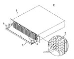
図1の如く、この光スプライスユニット1は、金属製のケース3の前面に、複数の光アダプタ4を上下左右に整列して配置した光アダプタパネル5を垂直に設け、光アダプタパネル5から前方に、光ファイバコード整線用の金属製の棚板6をケース3の底板7のほぼ延長上に水平に設け、棚板6の左右両端側に光ファイバコード整線用の合成樹脂製のクランプ8を設けたものにおけるものである。
As shown in FIG. 1, the
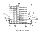
下部側の光アダプタ41に脱着頻度の少ないあるいは脱着不要な(以下単に「脱着頻度の少ない」と記載する)光ファイバコード91(図3)を光コネクタ接続し、それより上側の光アダプタ4に脱着頻度の多い光ファイバコード9(図3)を光コネクタ接続し、それと共に、棚板6の上側に配線保護用の金属製のカバー2を設け、棚板6とカバー2との間に、脱着頻度の少ない光ファイバコード91を配線し、カバー2の上側に脱着頻度の多い光ファイバコード9を配線している。
An optical fiber cord 9 1 (FIG. 3) is connected to the optical adapter 4 1 on the lower side with a low frequency of detachment or unnecessary (hereinafter simply referred to as “low frequency of detachment”). 4 is connected to the optical fiber cord 9 (FIG. 3) with a high frequency of attachment / detachment, and a
棚板6は、水平な底板部10の前端に垂直な立ち上げ板部11を折り曲げ形成し、底板部10の後端に、ケース3の左右端の前壁面にねじ締め等で固定するための固定板部12を垂直に立ち上げ形成して成るものである。立ち上げ板部11の内側(後面側)にカバー2が収容され、立ち上げ板部11は、前方へのカバー2の移動を規制するストッパとして作用すると共に、脱着頻度の少ない光ファイバコード91の前方への飛び出しを防止するガイドとして作用する。
The
クランプ8は上向きコの字状に形成され、前後一対のガイド杆8aがカバー2よりも高く突出し、前後一対のガイド杆8aの間に、下側と上側の光ファイバコード91,9すなわち脱着頻度の少ない光ファイバコード91と脱着頻度の多い光ファイバコード9とがカバー2を介して共に挿通される。クランプ8の形状は適宜設定可能であり、例えば上部開口8cを塞ぐ水平な可撓性の上杆部(図示せず)を設けたり、クランプ8の底部の水平な杆部8bを棚板6の底板部10と同一面に設けたり、あるいは排除したりすることも可能である。
The
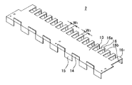
図2の如く、カバー2は、一枚の金属板を打ち抜き及び折り曲げ加工して形成され、水平な天板部13と、天板部13の前端において上下に互い違いに垂直に突設された複数の幅広の突板部14,15と、天板部13の後端から後方に櫛状に突出した複数本の側方視略L字状の幅狭な櫛歯部16とで構成されている。
As shown in FIG. 2, the
各櫛歯部16は、長い水平板部16aと下向きの短い垂直板部16bとで構成されている。左右端の櫛歯部161は他の櫛歯部16よりも少し幅広に形成されている。下向きの突板部(足部)15と櫛歯部16の垂直板部(足部)16bとは同じ突出高さである。各櫛歯部16の間の隙間W1は各アダプタ4,41(図1)W2の横幅よりも若干広く形成され、左右端を除く各櫛歯部16の幅W3は、左右方向の各アダプタ4,41の間の隙間W4よりも若干狭く形成され、図1の如く、各櫛歯部16の間に各アダプタ4,41を挟持する如くガタ付きなく保持する。
Each
これにより、カバー2の左右方向の移動が阻止される。櫛歯部16の垂直板部16bは下側の各アダプタ41の側面に上下方向の線接触で確実に当接する。櫛歯部16の水平部16aは上側と下側のアダプタ4,41の間(隙間)に位置することもある。上側と下側のアダプタ4,41は同じ仕様のものである。
Thereby, the movement of the
カバー2の下向きの突板部15が、図3の如く棚板6の立ち上げ板部11の内面(後面)に当接して、カバー2の前方への移動を阻止し、上向きの突板部14は、カバー2の上側に配線された脱着頻度の多い光ファイバコード9の前方への飛び出しを防ぐストッパ兼ガイドとして作用する。下向きの突板部15の下端と櫛歯部16の垂直板部26bの下端とが棚板6の水平な底板部10の上面に当接して、カバー2を安定に支持する。
The downward projecting
下向きの各突板部15の高さは、脱着頻度の少ない光ファイバコード91に対応する光アダプタ41の使用段数や、棚板6の立ち上げ板部11の高さ等に応じて適宜設定され、上向きの各突板部14の高さは、脱着頻度の多い光ファイバコード9の本数等に応じて適宜設定される。棚板6の立ち上げ板部11の高さは、脱着頻度の少ない光ファイバコード91に対応する光アダプタ41の使用段数等に応じて適宜設定される。
The height of the downward the protruding
本例では、図1,図3の如く、下から一段目(最下段)と二段目の各光アダプタ41に脱着頻度の少ない光ファイバコード91が接続され、下から三段目から最上段の各光アダプタ4に脱着頻度の多い光ファイバコード9が接続されている。
In the present example, FIG. 1, as shown in FIG. 3, first stage from the bottom (bottom) and less
図1の如く、カバー2の天板部13が棚板6の左右端のクランプ8の内側(間)に位置し、天板部13の左右両端がクランプ8の内側面に近接している。天板部13の左右端をクランプ8の内側面に当接させれば、櫛歯部16によるカバー2の左右方向の位置ずれ防止性を一層高めることはできる。実使用上は、櫛歯部16によるカバー2の左右方向の移動阻止のみで十分である。
As shown in FIG. 1, the
左右端の櫛歯部161の垂直板部16bを光アダプタパネル5の左右端側の垂直壁面17に当接させれば、前側の下向きの突板部15と共にカバー2の前後方向の移動(ガタ付き)を阻止可能である。本例においては、カバー2のねじ締め等の固定手段はあえて設けていない。カバー2の浮き上がりは、カバー2の天板部13の上面に上側の脱着頻度の多い光ファイバコード9(図3)が載ることで防止される。
If ask the
図3の如く、下から一段目と二段目のアダプタ41に脱着頻度の少ない各光ファイバコード91が接続されて、各光ファイバコード91が左右端のクランプ8(図1)に挿通案内された状態で、カバー2が棚板6に装着される。図1のカバー2の各櫛歯部16の間でアダプタ4の前側に位置する開口18は、例えば下側のアダプタ41に脱着頻度の少ない光ファイバコード91が接続されているか否かを目視する際に役立つ。
As shown in FIG. 3, the
図3において、カバー2の上側の脱着頻度の多い各光ファイバコード9は左右に曲げられて左右端のクランプ8(図1)に挿通案内される。図1の如く、カバー2には、各クランプ8の近傍と中央とにおいて前後一対の孔部19が設けられており、孔部19にバンド等(図示せず)を挿通して上下の各光ファイバコード9,91を同時に結束することができる。ケース3は、左右両側壁20の前端に設けた鍔部21で複数段のフレーム(図示せず)の適宜位置に停止固定される。
In FIG. 3, the
図3の如く、各光ファイバコード9,91は先端側のフェルールを有する光コネクタ22で各アダプタ4,41の前半部に嵌合し、係止アーム等の係止手段で固定されている。各アダプタ4,41の後半部には、ケース3内の各光ファイバコード(図示せず)が例えばフェルールを有する光コネクタ(図示せず)で嵌合し、係止アーム等の係止手段で固定されて、前半側の光コネクタ22に光接続される。ケース3内の各光ファイバコードを光コネクタ以外の手段で光アダプタ4,41に固定することも可能であり、光アダプタ4,41における前後の各光ファイバコード9,91の接続手段や係止手段は適宜設定可能である。
As shown in FIG. 3, the
前側(ケース外側)の光ファイバコード9,91が、例えばインタネットのような任意加入サービスの切換え、契約及びその解除に伴う脱着を行う光ファイバコードである。例えばテレビのような全加入サービス用の光ファイバコード91がカバー2の下側に隠されて(覆われて)安全に保護され、カバー2の上側の任意加入サービス用の光ファイバコード9の脱着時に、カバー下側の全加入サービス用の光ファイバコード91を誤って脱抜したり、全加入サービス用の光ファイバコード91の光コネクタ22に外部から衝撃等を与えたりする心配がない。
図4〜図6は、本発明に係る光スプライスユニットの他の実施形態(変形例)を示すものである。上記図1〜図3の光スプライスユニット1と同様の構成部分には同じ符号を付して詳細な説明を省略する。
4 to 6 show another embodiment (modification) of the optical splice unit according to the present invention. The same components as those in the
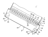
この光スプライスユニット1’は、基本的に図1〜図3の光スプライスユニット1と同様であるが、棚板6へのカバー2’の固定手段を設けると共に、クランプ8の近傍でカバー2’の両側に切欠部23を設けた点で相違している。
The
図4の如く、カバー2’の前端に、横長の突板部14’が立ち上げ形成されると共に、突板部14’の左右両側において一対の短い下向きの突板部15’が形成され、上向きの突板部14’はカバー上側の脱着頻度の多い光ファイバコード9(図6)に対するガイドとして作用し、下向きの各突板部15’に雄ねじ挿通用の孔(図示せず)が設けられ、孔に雄ねじ24を挿通して、棚板6の前端の上向きの立ち上げ板部11のタップ孔又は孔の後方のナット(図示せず)に螺合させて、上記固定手段を構成している。
As shown in FIG. 4, at the front end of the cover 2 ', a horizontally long projecting plate portion 14' is raised and formed, and a pair of short downward projecting plate portions 15 'are formed on both the left and right sides of the projecting plate portion 14'. The portion 14 'acts as a guide for the optical fiber cord 9 (Fig. 6) frequently attached and detached on the upper side of the cover. Each downwardly projecting plate portion 15' is provided with a male screw insertion hole (not shown). 24 is inserted and screwed into a tap hole of the upward rising
カバー2’にコード案内用の下向きの突板部15(図2)はなく、棚板6の前端の立ち上げ板部11がカバー下側の脱着頻度の多い光ファイバコード91をガイドする。カバー2’の後半の各櫛歯部16は、前例同様に各光アダプタ4,41を挟むように各光アダプタ4,41の側面に接して位置決めされている。図4,図5の如く、各櫛歯部16は左右方向の各光アダプタ4,41の間の隙間に奥深く入り込み、カバー下側の光アダプタ41から導出された脱着頻度の少ない光ファイバコード91を確実に保護している。
Cover 2 'in a downward protruding
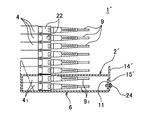
図3の例ではカバー2は棚板6から上向きに取り外されるが、図6の例では、カバー2’の前端のねじ24を外して、カバー2’を前方にスライドさせることで、カバー上側の脱着頻度の多い多数本の光ファイバコード9に邪魔されることなく、カバー2’をスムーズに取り外すことができる。これにより、カバー下側の脱着頻度の少ない少数本の光ファイバコード91のメンテナンス等を簡単に行うことができる。
In the example of FIG. 3, the
図4,図5の如く、カバー2’の左右両側の切欠部23は棚板上の左右端のクランプ8に対向して位置し、カバー前端の下向きの突板部15’の側端に続く前側の直線部23aと後側の湾曲部23bとで構成され、湾曲部23bが後半側の左右端の櫛歯部161に続いている。
As shown in FIGS. 4 and 5, the
切欠部23によって、カバー2’の側端からクランプ8までの距離L(図5)が長くなり、カバー上側の脱着頻度の多い光ファイバコード9(図6)をカバー2’の上面からクランプ8の底部8c側まで案内する際に、カバー2’の側端から光ファイバコード9が緩やかな角度で屈曲され、光ファイバコード9に作用する曲げ応力が小さくて済み、光ファイバコード9の許容曲げ仕様を十分に満足させることができると共に、クランプ9で光ファイバコード9を押さえた際のキンク(捩れ等)の発生も防止することができる。また、カバー2’を前方にスライドさせて外す際に、切欠部23に沿って光ファイバコード9をスムーズに摺接させて、光ファイバコード9の引っ掛かり等を防止することができる。
The
図4の如く、ケース3は、光アダプタパネル5を前端側に起立させたケース本体3aと、ケース本体3aの上部開口を覆うカバー部3b(図1)とで開閉可能に構成されており、ケース本体3aの左右端の垂直な鍔部25に棚板6がねじ締めで固定されている。ケース本体内に内側の各光ファイバケーブル(図示せず)がリール巻き等で余長吸収されつつ収容される。
As shown in FIG. 4, the
図5の如く、光アダプタパネル5は縦断面略L字状(上端の短い水平部26を含めると略コの字状)に形成され、底部側の水平部27がケース本体3aの底板部7に固定されている。図4の如く、上端の水平部26から垂直部28の底端にかけてスリット状の縦長孔29が複数列に設けられ、各縦長孔29に複数段に光アダプタ4,41が装着されている。図5の如く、カバー2’の櫛歯部16の後端の垂直部16bは光アダプタパネル5の垂直部28の前面に少しの隙間を存して対向している。
As shown in FIG. 5, the
なお、上記実施形態においては、カバー上側の光ファイバケーブル9とカバー下側の光ファイバケーブル91とでクランプ8を共通使用して構造の簡素化を図っているが、カバー2,2’にクランプ(図示せず)を立設し、カバー2,2’のクランプでカバー上側の光ファイバケーブル9を集束し、棚板6のクランプ8でカバー下側の光ファイバケーブル91を集束することも可能である。
In the above embodiment, although in
また、上記実施形態においては、棚板6の左右両側にクランプ8を配置したが、各光ファイバコード9,91の導出方向が一方向である場合には、棚板6の左右何れかにクランプ8を配置する。
In the above embodiment has been arranged a
また、上記図4の実施形態においては、棚板6の前端の立ち上げ部11で下側の光ファイバコード91をガイドしたが、例えば、図4において、立ち上げ部11を排除し、カバー2’の前端に図2の例のような上下の垂直な突板部14,15を設け、下向きの突板部15の一部に水平部(図示せず)を設け、その水平部を棚板6の水平部10にねじ等で固定し、下向きの突板部15で下側の光ファイバコード91をガイドすることも可能である。
Further, in the embodiment of FIG 4 has been guided
1,1’ 光スプライスユニット
2,2’ カバー
3 ケース
4,41 光アダプタ
5 光アダプタパネル
6 棚板
8 クランプ
9,91 光ファイバコード
11 立ち上げ部
14,15 突板部
14’,15’ 突板部
16 櫛歯部
16b 垂直部(足部)
23 切欠部
24 雄ねじ
DESCRIPTION OF
23
Claims (6)
前記棚板の上側にカバーが配設され、該カバーの下側の前記光アダプタに脱着頻度の少ない又は無い光ファイバコードが接続され、該カバーの上側の前記光アダプタに脱着頻度の多い光ファイバコードが接続され、該棚板と該カバーとの間に脱着頻度の少ない又は無い光ファイバコードが配線され、該カバーの上側に脱着頻度の多い光ファイバコードが配線されたことを特徴とする光スプライスユニット。 An optical adapter panel in which a plurality of optical adapters are arranged vertically and horizontally, a case in which the optical adapter panel is arranged on the front end side, a shelf board that projects forward from the bottom of the case to the optical adapter panel, In an optical splice unit comprising a plurality of optical fiber cords connected to the optical adapter on the upper side of the shelf board,
A cover is disposed on the upper side of the shelf plate, and an optical fiber cord with little or no detachment frequency is connected to the optical adapter on the lower side of the cover, and an optical fiber with a high detachment frequency is attached to the optical adapter on the upper side of the cover. An optical fiber cord is connected, an optical fiber cord having a low or no detachment frequency is wired between the shelf board and the cover, and an optical fiber cord having a high detachment frequency is wired above the cover Splice unit.
Priority Applications (1)
| Application Number | Priority Date | Filing Date | Title |
|---|---|---|---|
| JP2008260261A JP5248260B2 (en) | 2008-10-07 | 2008-10-07 | Optical splice unit |
Applications Claiming Priority (1)
| Application Number | Priority Date | Filing Date | Title |
|---|---|---|---|
| JP2008260261A JP5248260B2 (en) | 2008-10-07 | 2008-10-07 | Optical splice unit |
Publications (2)
| Publication Number | Publication Date |
|---|---|
| JP2010091695A true JP2010091695A (en) | 2010-04-22 |
| JP5248260B2 JP5248260B2 (en) | 2013-07-31 |
Family
ID=42254495
Family Applications (1)
| Application Number | Title | Priority Date | Filing Date |
|---|---|---|---|
| JP2008260261A Expired - Fee Related JP5248260B2 (en) | 2008-10-07 | 2008-10-07 | Optical splice unit |
Country Status (1)
| Country | Link |
|---|---|
| JP (1) | JP5248260B2 (en) |
Cited By (1)
| Publication number | Priority date | Publication date | Assignee | Title |
|---|---|---|---|---|
| JP2013037173A (en) * | 2011-08-08 | 2013-02-21 | Osaki Electric Co Ltd | Adapter identifying jig |
Citations (4)
| Publication number | Priority date | Publication date | Assignee | Title |
|---|---|---|---|---|
| JPH07132122A (en) * | 1993-11-09 | 1995-05-23 | Olympus Optical Co Ltd | Control system for medical treatment |
| JP2002040287A (en) * | 2000-07-24 | 2002-02-06 | Sumitomo Electric Ind Ltd | Member for preventing erroneous detachment of optical connector, and optical connector device |
| JP2004361893A (en) * | 2003-06-09 | 2004-12-24 | Kawamura Electric Inc | Splicing unit |
| JP2006080009A (en) * | 2004-09-10 | 2006-03-23 | Jst Mfg Co Ltd | Jack |
-
2008
- 2008-10-07 JP JP2008260261A patent/JP5248260B2/en not_active Expired - Fee Related
Patent Citations (4)
| Publication number | Priority date | Publication date | Assignee | Title |
|---|---|---|---|---|
| JPH07132122A (en) * | 1993-11-09 | 1995-05-23 | Olympus Optical Co Ltd | Control system for medical treatment |
| JP2002040287A (en) * | 2000-07-24 | 2002-02-06 | Sumitomo Electric Ind Ltd | Member for preventing erroneous detachment of optical connector, and optical connector device |
| JP2004361893A (en) * | 2003-06-09 | 2004-12-24 | Kawamura Electric Inc | Splicing unit |
| JP2006080009A (en) * | 2004-09-10 | 2006-03-23 | Jst Mfg Co Ltd | Jack |
Cited By (1)
| Publication number | Priority date | Publication date | Assignee | Title |
|---|---|---|---|---|
| JP2013037173A (en) * | 2011-08-08 | 2013-02-21 | Osaki Electric Co Ltd | Adapter identifying jig |
Also Published As
| Publication number | Publication date |
|---|---|
| JP5248260B2 (en) | 2013-07-31 |
Similar Documents
| Publication | Publication Date | Title |
|---|---|---|
| CN101384938B (en) | Fiber optic splitter module | |
| CA3087633A1 (en) | Push-pull boot connector for fiber optic cables | |
| US6785460B2 (en) | Tool to remove a ferrule from a receptacle | |
| CA2729997C (en) | Optical adapter | |
| US8985876B2 (en) | Ferrule holder | |
| JP2012212103A (en) | Optical fiber adapter with shutter member | |
| JP2019132929A (en) | Optical connector | |
| US9122022B2 (en) | Debris reducing multi-fiber connector and adapter and associated methods | |
| JP4087046B2 (en) | Optical cable adapter or connector and its mounting member | |
| JP4197588B2 (en) | Assembly including plastic optical fiber outlet and plug | |
| JP5248260B2 (en) | Optical splice unit | |
| JP2006235557A (en) | Optical plug socket | |
| JP4270255B2 (en) | Optical fiber outlet | |
| JP2008032843A (en) | Optical wiring tray | |
| JP2006208738A (en) | Optical connector | |
| JP6236646B2 (en) | Optical connection box | |
| JP6796283B2 (en) | How to remove the transmission device, cable guide set, and board | |
| JP2002333548A (en) | Optical relay connector apparatus and optical relay connector | |
| JP2011100004A (en) | Two-core optical plug socket | |
| JP2014126667A (en) | Branch structure, kit for termination processing and termination method of optical fiber cable | |
| KR101411581B1 (en) | optical fiber connecter | |
| JP5703471B2 (en) | Mounting structure of fixed member to fixing member | |
| JP6919894B2 (en) | Fiber Optic Cable Guide | |
| JP4840572B2 (en) | Optical module and optical junction box | |
| JP2007114314A (en) | Optical plug socket |
Legal Events
| Date | Code | Title | Description |
|---|---|---|---|
| A621 | Written request for application examination |
Free format text: JAPANESE INTERMEDIATE CODE: A621 Effective date: 20110830 |
|
| A977 | Report on retrieval |
Free format text: JAPANESE INTERMEDIATE CODE: A971007 Effective date: 20120611 |
|
| A131 | Notification of reasons for refusal |
Free format text: JAPANESE INTERMEDIATE CODE: A131 Effective date: 20120626 |
|
| A711 | Notification of change in applicant |
Free format text: JAPANESE INTERMEDIATE CODE: A712 Effective date: 20120926 |
|
| RD03 | Notification of appointment of power of attorney |
Free format text: JAPANESE INTERMEDIATE CODE: A7423 Effective date: 20120927 |
|
| RD04 | Notification of resignation of power of attorney |
Free format text: JAPANESE INTERMEDIATE CODE: A7424 Effective date: 20121005 |
|
| TRDD | Decision of grant or rejection written | ||
| A01 | Written decision to grant a patent or to grant a registration (utility model) |
Free format text: JAPANESE INTERMEDIATE CODE: A01 Effective date: 20130402 |
|
| A61 | First payment of annual fees (during grant procedure) |
Free format text: JAPANESE INTERMEDIATE CODE: A61 Effective date: 20130410 |
|
| R150 | Certificate of patent or registration of utility model |
Ref document number: 5248260 Country of ref document: JP Free format text: JAPANESE INTERMEDIATE CODE: R150 Free format text: JAPANESE INTERMEDIATE CODE: R150 |
|
| FPAY | Renewal fee payment (event date is renewal date of database) |
Free format text: PAYMENT UNTIL: 20160419 Year of fee payment: 3 |
|
| R250 | Receipt of annual fees |
Free format text: JAPANESE INTERMEDIATE CODE: R250 |
|
| R250 | Receipt of annual fees |
Free format text: JAPANESE INTERMEDIATE CODE: R250 |
|
| R250 | Receipt of annual fees |
Free format text: JAPANESE INTERMEDIATE CODE: R250 |
|
| R250 | Receipt of annual fees |
Free format text: JAPANESE INTERMEDIATE CODE: R250 |
|
| R250 | Receipt of annual fees |
Free format text: JAPANESE INTERMEDIATE CODE: R250 |
|
| R250 | Receipt of annual fees |
Free format text: JAPANESE INTERMEDIATE CODE: R250 |
|
| LAPS | Cancellation because of no payment of annual fees |