JP2010091069A - Elastic body shaft coupling and construction machine - Google Patents
Elastic body shaft coupling and construction machine Download PDFInfo
- Publication number
- JP2010091069A JP2010091069A JP2008263469A JP2008263469A JP2010091069A JP 2010091069 A JP2010091069 A JP 2010091069A JP 2008263469 A JP2008263469 A JP 2008263469A JP 2008263469 A JP2008263469 A JP 2008263469A JP 2010091069 A JP2010091069 A JP 2010091069A
- Authority
- JP
- Japan
- Prior art keywords
- torque transmission
- elastic body
- rotating body
- elastic
- transmission surface
- Prior art date
- Legal status (The legal status is an assumption and is not a legal conclusion. Google has not performed a legal analysis and makes no representation as to the accuracy of the status listed.)
- Pending
Links
- 230000008878 coupling Effects 0.000 title claims abstract description 18
- 238000010168 coupling process Methods 0.000 title claims abstract description 18
- 238000005859 coupling reaction Methods 0.000 title claims abstract description 18
- 238000010276 construction Methods 0.000 title claims description 6
- 230000005540 biological transmission Effects 0.000 claims description 74
- 230000002093 peripheral effect Effects 0.000 claims description 4
- 239000002184 metal Substances 0.000 description 25
- 238000003780 insertion Methods 0.000 description 14
- 230000037431 insertion Effects 0.000 description 14
- 238000013459 approach Methods 0.000 description 1
- 238000010586 diagram Methods 0.000 description 1
- 230000000694 effects Effects 0.000 description 1
- 239000000463 material Substances 0.000 description 1
- 230000004048 modification Effects 0.000 description 1
- 238000012986 modification Methods 0.000 description 1
- 238000000465 moulding Methods 0.000 description 1
- 239000011347 resin Substances 0.000 description 1
- 229920005989 resin Polymers 0.000 description 1
Images



Landscapes
- Arrangement Or Mounting Of Propulsion Units For Vehicles (AREA)
Abstract
Description
本発明は、回転体のトルクを弾性体を介して他の回転体に伝達する弾性体軸継手および建設機械に関する。 The present invention relates to an elastic shaft joint that transmits torque of a rotating body to another rotating body via an elastic body, and a construction machine.
従来より、エンジンの駆動トルクを弾性体を介して被駆動機器に伝達するようにした弾性体軸継手が知られている(例えば特許文献1参照)。この特許文献1記載の弾性体軸継手では、エンジンの出力軸に設けられたハブと被駆動機器の入力軸に設けられたハブを弾性体を介して連結するとともに、軸間の同心を保つためにハブの連結部に軸受けを設ける。
2. Description of the Related Art Conventionally, an elastic shaft coupling that transmits engine driving torque to a driven device via an elastic body is known (see, for example, Patent Document 1). In the elastic shaft joint described in
ところで、エンジンの出力軸と被駆動機器の入力軸とは、弾性体を介して軸方向に嵌合して連結されるが、この嵌合の組立性を容易にするため、弾性体とハブの接触面の間には、通常、隙間が設けられる。 By the way, the output shaft of the engine and the input shaft of the driven device are connected in an axial direction through an elastic body, and in order to facilitate the assembly of this connection, the elastic body and the hub are connected. A gap is usually provided between the contact surfaces.
しかしながら、軸継手に作用するトルクは、エンジン回転速度の変動や負荷変動等により変化するため、弾性体とハブの接触面の間に隙間を設けると、弾性体の摺動磨耗を引き起こし、製品寿命が低下するおそれがある。 However, since the torque acting on the shaft coupling changes due to fluctuations in engine rotation speed, load fluctuations, etc., providing a gap between the elastic body and the contact surface of the hub causes sliding wear of the elastic body, resulting in product life. May decrease.
本発明による弾性体軸継手は、軸方向に同心状に第1の回転体と第2の回転体とが配置され、これら第1の回転体および第2の回転体の端部に、軸方向に互いに嵌合し合うようにそれぞれ周方向に対向して複数のトルク伝達面が形成されるとともに、これら第1の回転体のトルク伝達面と第2の回転体のトルク伝達面との間に軸方向から介装された弾性体を介して、第1の回転体のトルクを第2の回転体に伝達する弾性体軸継手であって、複数のトルク伝達面のうち、第1の回転体と弾性体とが接触する第1のトルク伝達面および第2の回転体と弾性体とが接触する第2のトルク伝達面の少なくとも一方は、弾性体を介して第1の回転体と第2の回転体を嵌合した際に弾性体と少なくとも一方の回転体とが互いに密着するように軸方向にテーパ状に形成されることを特徴とする。 In the elastic shaft joint according to the present invention, the first rotating body and the second rotating body are arranged concentrically in the axial direction, and the end portions of the first rotating body and the second rotating body are arranged in the axial direction. A plurality of torque transmission surfaces are formed facing each other in the circumferential direction so as to be fitted to each other, and between the torque transmission surface of the first rotating body and the torque transmission surface of the second rotating body. An elastic shaft coupling for transmitting torque of a first rotating body to a second rotating body via an elastic body interposed from an axial direction, wherein the first rotating body is a first rotating body among a plurality of torque transmitting surfaces. At least one of the first torque transmission surface that contacts the elastic body and the second torque transmission surface that contacts the second rotating body and the elastic body is connected to the first rotating body and the second through the elastic body. So that the elastic body and at least one of the rotating bodies are in close contact with each other when the rotating bodies are fitted together. Characterized in that it is formed to Jo.
本発明によれば、回転体と弾性体とが接触するトルク伝達面を軸方向にテーパ状に形成するようにしたので、トルク伝達面同士を密着させることができ、弾性体の磨耗を抑えることができる。 According to the present invention, since the torque transmission surface that contacts the rotating body and the elastic body is formed in a tapered shape in the axial direction, the torque transmission surfaces can be brought into close contact with each other, and wear of the elastic body can be suppressed. Can do.
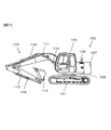
以下、図1〜図11を参照して本発明による弾性体軸継手の実施の形態について説明する。図1は、本実施の形態に係る弾性体軸継手を有する建設機械の一例である油圧ショベルの側面図である。油圧ショベルは、走行体101と、走行体101上に旋回可能に搭載された旋回体102と、旋回体102に回動可能に軸支された作業用フロント103とを有する。旋回体102のフレーム105には運転室104が搭載され、その後方にはエンジン室106が設けられ、フレーム105の後端部にカウンタウエイト107が支持されている。作業用フロント103は、ブーム111と、アーム112と、バケット113とを有し、これらはそれぞれ油圧シリンダ114〜116により駆動される。
Hereinafter, an embodiment of an elastic shaft joint according to the present invention will be described with reference to FIGS. FIG. 1 is a side view of a hydraulic excavator that is an example of a construction machine having an elastic shaft joint according to the present embodiment. The hydraulic excavator includes a
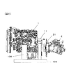
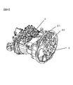
図2は、エンジン室106内の要部構成を示す図である。フレーム105上にはブラケット108を介してエンジン1が横置きに支持されている。エンジン1の側方には油圧ポンプ2が設けられ、エンジン1のフライホイールハウジング11に油圧ポンプ2のポンプフランジ21が締結される。エンジン1の出力軸には、弾性体軸継手を介して油圧ポンプ2の入力軸が連結される。
FIG. 2 is a diagram illustrating a configuration of a main part in the
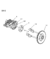
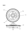
図3は、本実施の形態に係る弾性体軸継手の分解斜視図(エンジン側から見た斜視図)であり、図4はその要部拡大図である。エンジン1の出力軸の端部には、フライホイール12が一体に取り付けられ、フライホイール12の端面には、ボルト14によりホイール金具13が取り付けられる。図5(a)は、フライホイール12の正面図(図3の矢視V図)であり、図5(b)は側面図である。図5に示すようにホイール金具13は、周方向に等間隔に複数(図では4つ)取り付けられ、各ホイール金具13の周方向両端面にそれぞれトルク伝達面130が形成されている。
FIG. 3 is an exploded perspective view (a perspective view seen from the engine side) of the elastic shaft coupling according to the present embodiment, and FIG. 4 is an enlarged view of a main part thereof. A
図3,4に示すように油圧ポンプ2の入力軸の端部には、トルク伝達用のハブ22がポンプ2に一体に取り付けられている。ハブ22は、ポンプ入力軸に固定される回転軸24と、回転軸24の外周面から径方向外側に突出して設けられる複数のポンプ金具23とを有する。ポンプ金具23は、ホイール金具13と同数だけ周方向等間隔に設けられ、各ポンプ金具23の周方向両端面にそれぞれトルク伝達面230が形成されている。
As shown in FIGS. 3 and 4, a
図4に示すように弾性体3は、金具13,23のトルク伝達面130,230に密着するトルク面密着部31と、ポンプ金具23の軸方向端面に密着する軸端面密着部32と、回転軸24の外周面に密着するハブ面密着部33とを一体に有する。各トルク面密着部31の内側にはトルク伝達面310が形成され、外側にはトルク伝達面311が形成されている。トルク伝達面310の間には金具挿入空間SP1が、トルク伝達面311の間には金具挿入空間SP2がそれぞれ形成され、金具挿入空間SP1とSP2は、トルク伝達面310,311を介して周方向に交互に形成されている。弾性体3は例えば樹脂材からなり、一体成形により形成される。
As shown in FIG. 4, the
エンジン1の出力軸にポンプ2の入力軸を連結する際は、まず、弾性体3の金具挿入空間SP1に軸方向からポンプ金具23を挿入し、弾性体3をハブ22に取り付ける。これにより図6に示すようにハブ22の外側表面が弾性体3により覆われる。
When connecting the input shaft of the
この状態で、図2に示すようにホイールフランジ11にポンプフランジ21を締結すると、金具挿入空間SP2内に軸方向からホイール金具13が挿入される。これにより弾性体3を介してホイール金具13とポンプ金具23が一体に連結され、弾性体3と金具13,23がフライホイール12の回転に伴い一体に回転する。このような弾性体軸継手では、トルク伝達面130と230の間に弾性体3が挟まれ、弾性体3を介してエンジン1からのトルクが油圧ポンプ2に伝達されため、エンジン側とポンプ側との軸ずれや、エンジン1のトルク変動等を弾性体3で吸収することができ、滑らかなトルク伝達が可能である。
In this state, when the
この場合、金具13,23のトルク伝達面130,230と、これに接する弾性体3のトルク伝達面310,311とを隙間なく形成すると、金具挿入空間SP1,SP2内への金具13,23の挿入が困難となり、組立性が悪化する。一方、トルク伝達面130,230と310,311との間に隙間を設けると、エンジン回転数やポンプ負荷が変動して伝達トルクが変化した際に、トルク伝達面310,311に作用する面圧が変化し、弾性体3が摺動する。その結果、弾性体3が磨耗し、製品寿命が低下する。そこで、本実施の形態では、以下のように金具13,23および弾性体3のトルク伝達面130,230,310,311を構成する。
In this case, when the torque transmission surfaces 130 and 230 of the
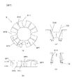
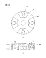
図7(a),(b)は、それぞれ弾性体3の正面図および側面図であり、図7(c),(d)は、それぞれ図7(a)のc−c線断面図およびd−d線断面図である。図8(a),(b)は、それぞれハブ22の正面図および側面図であり、図8(c)は、図8(a)のc−c線断面図である。図9(a),(b)は、それぞれフライホイール12に取り付けられたホイール金具13の正面図および側面図であり、図9(c)は、図9(a)のc−c線断面図である。図10(a),(b)は、図7〜図9の各部品を組み立てた状態を示す正面図および側面図である。なお、図7〜図10の側面図は、上方がエンジン側、下方がポンプ側として示している。
7A and 7B are a front view and a side view, respectively, of the
図7に示すように弾性体3の各トルク伝達面310は、それぞれ軸方向にテーパ状に形成され、金具挿入空間SP1はポンプ側にかけて徐々に拡大している。また、弾性体3の各トルク伝達面311は、それぞれ軸方向にテーパ状に形成され、金具挿入空間SP2はエンジン側にかけて徐々に拡大している。図7(c),(d)に示すように周方向両側のトルク伝達面310の軸線に対する角度(テーパ角度θ)をそれぞれθ1、θ2、周方向両側のトルク伝達面311の軸線に対する角度をそれぞれθ3,θ4とすると、θ1=θ2=θ3=θ4とされている。
As shown in FIG. 7, each
図8に示すようにポンプ金具23の各トルク伝達面230は、それぞれ軸方向に沿ってテーパ状に形成され、エンジン側にかけて先細となっている。トルク伝達面230は弾性体3のトルク伝達面310に対応した形状をなし、図8(c)に示すように各トルク伝達面230のテーパ角度θは図7(c)のθ1、θ2に等しい。これによりポンプ金具23の先端部は金具挿入空間SP1の入口部よりも十分に小さいため、図8(c)の矢印に示すように弾性体3を軸方向からポンプ金具23に容易に嵌合することができる。その結果、ホイールフランジ11とポンプフランジ21との締結により弾性体3が弾性変形し、トルク伝達面230,310同士を隙間なく密着させることができる。
As shown in FIG. 8, each
図9に示すようにホイール金具13の各トルク伝達面130は、それぞれ軸方向に沿ってテーパ状に形成され、ポンプ側にかけて先細となっている。トルク伝達面130は弾性体3のトルク伝達面311に対応した形状をなし、図9(c)に示すように各トルク伝達面130のテーパ角度θは図7(d)のθ3、θ4に等しい。これによりホイール金具13の先端部は金具挿入空間SP2の入口部よりも十分に小さいため、図9(c)の矢印に示すように軸方向から弾性体3に容易に嵌合することができる。その結果、ホイールフランジ11とポンプフランジ21との締結により弾性体3が弾性変形し、トルク伝達面130,311同士を隙間なく密着させることができる。
As shown in FIG. 9, each
エンジン1の出力軸に油圧ポンプ2の入力軸を連結した状態では、図10に示すように金具13,23と弾性体3はトルク伝達面130,230,310,311を介して密着している。このため、エンジン回転数やポンプ負荷が変動した場合の弾性体3の摺動を防ぐことができ、弾性体3の磨耗を低減できる。
In a state where the input shaft of the
本実施の形態によれば以下のような作用効果を奏することができる。
(1)フライホイール12の端面にホイール金具13を設け、さらにこれと嵌合するように油圧ポンプ2の端部にポンプ金具23を設け、各金具13,23のトルク伝達面130,230の間にトルク伝達面310,311を介して弾性体3を介装し、エンジン1のトルクを弾性体3を介して油圧ポンプ2に伝達するとともに、弾性体3を介したフライホイール12とハブ22の嵌合時に金具13,23と弾性体3が互いに密着するようにトルク伝達面130,230,310,311をそれぞれテーパ状に形成するようにした。これにより弾性体3を介してフライホイール12に油圧ポンプ2のハブ22を容易に組み付けることができるとともに、トルク伝達面310,311における弾性体3の摺動を抑えることができ、弾性体3の磨耗による製品寿命の低下を防ぐことができる。
According to the present embodiment, the following operational effects can be achieved.
(1) A wheel fitting 13 is provided on the end face of the
(2)トルク伝達面230,310のテーパ角度θ1,θ2とトルク伝達面130,311のテーパ角度θ3,θ4を等しくするようにしたので(θ1=θ4、θ2=θ3)、トルク伝達面310,311間の弾性体3の軸方向の肉厚が一定となり、弾性体3を均一に弾性変形させることができる。
(3)トルク伝達面310および311の両側のテーパ角度θ1,θ2およびθ3,θ4をそれぞれ等しくするようにしたので(θ1=θ2、θ3=θ4)、金具挿入空間SP1,SP2の入口が広くなり、弾性体3を金具13,23の間に容易に取り付けることができる。
(4)エンジン1のフライホイール12と油圧ポンプ2を連結する軸継手のトルク伝達面をテーパ形状としたので、エンジン回転速度の変動や油圧ポンプ2の負荷が大きく変動した場合であっても、弾性体3の磨耗を良好に抑えることができる。
(2) Since the taper angles θ1, θ2 of the torque transmission surfaces 230, 310 and the taper angles θ3, θ4 of the torque transmission surfaces 130, 311 are made equal (θ1 = θ4, θ2 = θ3), the torque transmission surfaces 310, The thickness of the
(3) Since the taper angles θ1, θ2, θ3, and θ4 on both sides of the torque transmission surfaces 310 and 311 are made equal (θ1 = θ2, θ3 = θ4), the entrances of the metal fitting insertion spaces SP1 and SP2 are widened. The
(4) Since the torque transmission surface of the shaft coupling that connects the
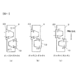
なお、上記実施の形態では、金具挿入空間SP1内に設けられた周方向両側のトルク伝達面310の各テーパ角θ1,θ2、および金具挿入空間SP2内に設けられた周方向両側のトルク伝達面311の各テーパ角θ3,θ4を、図11(a)に示すようにθ1=θ2=θ3=θ4としたが、少なくとも弾性体3と金具13,23が互いに密着するようにトルク伝達面130,230,310,311をテーパ状に形成するのであれば、トルク伝達面の構成はこれに限らない。
In the above embodiment, the taper angles θ1, θ2 of the torque transmission surfaces 310 on both sides in the circumferential direction provided in the metal fitting insertion space SP1 and the torque transmission surfaces on both sides in the circumferential direction provided in the metal fitting insertion space SP2. The taper angles θ3 and θ4 of 311 are set to θ1 = θ2 = θ3 = θ4 as shown in FIG. 11A, but at least the
例えば図11(b)に示すようにθ1とθ2、θ3とθ4それぞれ等しくするとともに、θ1とθ2をθ3とθ4より小さくしてもよい。これによりホイール金具13とポンプ金具23の製造メーカーが異なる等により金具13,23のテーパ角が互いに異なる場合にも対応可能である。図11(c)に示すようにエンジン1の出力軸が一方向に回転可能である場合には、その回転方向のトルク伝達面のテーパ角θ1,θ4を反回転方向のトルク伝達面のテーパ角θ2,θ3より小さくしてもよい。これによりエンジン1の回転方向に対するトルク伝達面の角度が垂直に近づき、エンジン1のトルクを油圧ポンプ2に良好に伝達することができる。
For example, as shown in FIG. 11B, θ1 and θ2, θ3 and θ4 may be made equal, and θ1 and θ2 may be made smaller than θ3 and θ4. Accordingly, it is possible to cope with cases where the taper angles of the
上記実施の形態では、ホイール金具13と弾性体3とが接触するトルク伝達面130,311(第1のトルク伝達面)およびポンプ金具23と弾性体3とが接触するトルク伝達面230,310(第2のトルク伝達面)をそれぞれテーパ状としたが、いずれか一方のみテーパ状にしたのでもよい。第1の回転体としてエンジン1のフライホイール12の端面にホイール金具13(第1のブロック)を設け、第2の回転体として油圧ポンプ2の出力軸の端部の周面にポンプ金具23(第2のブロック)を設けるようにしたが、第1の回転体と第2の回転体の構成はこれに限らない。エンジン1と油圧ポンプ2を連結する軸継手部だけでなく、他の軸継手部も上述したのと同様に構成することができる。
In the above embodiment, the torque transmission surfaces 130 and 311 (first torque transmission surface) where the wheel fitting 13 and the
以上では、油圧ショベルに適用する例を示したが、他の建設機械にも適用可能である。すなわち、本発明の特徴、機能を実現できる限り、本発明は実施の形態の弾性体軸継手に限定されない。 Although the example applied to the hydraulic excavator has been described above, the present invention can also be applied to other construction machines. That is, the present invention is not limited to the elastic shaft coupling according to the embodiment as long as the features and functions of the present invention can be realized.
1 エンジン
2 油圧ポンプ
3 弾性体
12 フライホイール
13 ホイール金具
22 ハブ
23 ポンプ金具
130,230,310,311 トルク伝達面
θ1〜θ4 テーパ角
DESCRIPTION OF
Claims (5)
前記複数のトルク伝達面のうち、前記第1の回転体と前記弾性体とが接触する第1のトルク伝達面および前記第2の回転体と前記弾性体とが接触する第2のトルク伝達面の少なくとも一方は、前記弾性体を介して前記第1の回転体と前記第2の回転体を嵌合した際に前記弾性体と前記少なくとも一方の回転体とが互いに密着するように軸方向にテーパ状に形成されることを特徴とする弾性体軸継手。 A first rotator and a second rotator are arranged concentrically in the axial direction, and the end portions of the first rotator and the second rotator are fitted to each other in the axial direction. A plurality of torque transmission surfaces are formed opposite to each other in the circumferential direction, and an elastic body interposed between the torque transmission surface of the first rotating body and the torque transmission surface of the second rotating body from the axial direction An elastic shaft coupling that transmits the torque of the first rotating body to the second rotating body via
Of the plurality of torque transmission surfaces, a first torque transmission surface that contacts the first rotating body and the elastic body and a second torque transmission surface that contacts the second rotating body and the elastic body. At least one of them in the axial direction so that the elastic body and the at least one rotating body are in close contact with each other when the first rotating body and the second rotating body are fitted via the elastic body. An elastic shaft coupling formed in a tapered shape.
前記第1のトルク伝達面および前記第2のトルク伝達面は、それぞれ軸方向にテーパ状に形成されるとともに、前記第1のトルク伝達面の軸線に対するなす角度および前記第2のトルク伝達面の軸線に対するなす角度は、互いに等しいことを特徴とする弾性体軸継手。 In the elastic body shaft coupling according to claim 1,
The first torque transmission surface and the second torque transmission surface are each formed in a taper shape in the axial direction, and an angle formed with respect to the axis of the first torque transmission surface and the second torque transmission surface An elastic shaft joint characterized in that angles formed with respect to an axis are equal to each other.
前記第1の回転体は一方向に回転可能であり、前記第1の回転体の回転方向における前記第1のトルク伝達面およびこれに対向する前記第2のトルク伝達面の軸線に対するなす角度は、前記第1の回転体の反回転方向における前記第1のトルク伝達面およびこれに対向する前記第2のトルク伝達面の軸線に対するなす角度よりも小さいことを特徴とする弾性体軸継手。 In the elastic body shaft coupling according to claim 1,
The first rotating body is rotatable in one direction, and an angle formed with respect to an axis of the first torque transmitting surface and the second torque transmitting surface facing the first torque transmitting surface in the rotating direction of the first rotating body is An elastic shaft coupling characterized by being smaller than an angle between the first torque transmission surface in the counter-rotating direction of the first rotating body and the axis of the second torque transmission surface facing the first torque transmission surface.
前記第1の回転体は、エンジンのフライホイールの軸方向端面に、周方向に間隔を開けて設けられた複数の第1のブロックを有し、
前記第2の回転体は、油圧ポンプの回転軸の周面に設けられた複数の第2のブロックを有し、
前記第1のブロックと前記弾性体との接触面および前記第2のブロックと前記弾性体との接触面に、それぞれ前記第1のトルク伝達面および前記第2のトルク伝達面が形成されることを特徴とする弾性体軸継手。 In the elastic body shaft coupling according to any one of claims 1 to 3,
The first rotating body has a plurality of first blocks provided at intervals in the circumferential direction on an axial end surface of an engine flywheel;
The second rotating body has a plurality of second blocks provided on a peripheral surface of a rotating shaft of a hydraulic pump,
The first torque transmission surface and the second torque transmission surface are formed on the contact surface between the first block and the elastic body and the contact surface between the second block and the elastic body, respectively. An elastic shaft joint characterized by
Priority Applications (1)
| Application Number | Priority Date | Filing Date | Title |
|---|---|---|---|
| JP2008263469A JP2010091069A (en) | 2008-10-10 | 2008-10-10 | Elastic body shaft coupling and construction machine |
Applications Claiming Priority (1)
| Application Number | Priority Date | Filing Date | Title |
|---|---|---|---|
| JP2008263469A JP2010091069A (en) | 2008-10-10 | 2008-10-10 | Elastic body shaft coupling and construction machine |
Publications (1)
| Publication Number | Publication Date |
|---|---|
| JP2010091069A true JP2010091069A (en) | 2010-04-22 |
Family
ID=42253992
Family Applications (1)
| Application Number | Title | Priority Date | Filing Date |
|---|---|---|---|
| JP2008263469A Pending JP2010091069A (en) | 2008-10-10 | 2008-10-10 | Elastic body shaft coupling and construction machine |
Country Status (1)
| Country | Link |
|---|---|
| JP (1) | JP2010091069A (en) |
Cited By (5)
| Publication number | Priority date | Publication date | Assignee | Title |
|---|---|---|---|---|
| JP2012137137A (en) * | 2010-12-27 | 2012-07-19 | Hitachi Constr Mach Co Ltd | Shaft coupling of construction machine |
| CN102758855A (en) * | 2012-07-20 | 2012-10-31 | 浙江博盟精工机械有限公司 | Connector |
| CN103062234A (en) * | 2011-10-20 | 2013-04-24 | 德昌电机(深圳)有限公司 | Coupling and coupling output shaft combination |
| JP2013174105A (en) * | 2012-02-27 | 2013-09-05 | Hitachi Constr Mach Co Ltd | Construction machine |
| JP2020118255A (en) * | 2019-01-25 | 2020-08-06 | 株式会社デンソー | Joint device and motor |
-
2008
- 2008-10-10 JP JP2008263469A patent/JP2010091069A/en active Pending
Cited By (5)
| Publication number | Priority date | Publication date | Assignee | Title |
|---|---|---|---|---|
| JP2012137137A (en) * | 2010-12-27 | 2012-07-19 | Hitachi Constr Mach Co Ltd | Shaft coupling of construction machine |
| CN103062234A (en) * | 2011-10-20 | 2013-04-24 | 德昌电机(深圳)有限公司 | Coupling and coupling output shaft combination |
| JP2013174105A (en) * | 2012-02-27 | 2013-09-05 | Hitachi Constr Mach Co Ltd | Construction machine |
| CN102758855A (en) * | 2012-07-20 | 2012-10-31 | 浙江博盟精工机械有限公司 | Connector |
| JP2020118255A (en) * | 2019-01-25 | 2020-08-06 | 株式会社デンソー | Joint device and motor |
Similar Documents
| Publication | Publication Date | Title |
|---|---|---|
| US5284455A (en) | Shaft coupling having multiple rib connectors | |
| JP2014109323A (en) | Gear device | |
| CN101042145B (en) | Rotary machinery | |
| JP6813250B2 (en) | Bearing equipment and construction machinery | |
| JP2005168339A (en) | Portable working machine | |
| CN205278284U (en) | Harmonic reducer | |
| JP4616376B2 (en) | Support structure of cylindrical member in automatic transmission | |
| CN103038526A (en) | Buffering member, shaft coupled structure, and a uniaxial eccentric screw pump | |
| JP2010091068A (en) | Elastic shaft coupling and construction machine | |
| CN211579775U (en) | Flange type flexible connection structure for connecting outer rotor motor and driven shaft | |
| CN211579774U (en) | Universal joint type flexible connection structure for connecting outer rotor motor and driven shaft | |
| JP6059922B2 (en) | Coupling | |
| JP2018105289A (en) | Trochoid pump | |
| CN223363966U (en) | Motor assembly, suspension system and vehicle | |
| CN211901338U (en) | Chuck type flexible connection structure for connecting outer rotor motor and driven shaft | |
| CN115243915A (en) | Connecting structure of transmission shaft and transmission shaft with same | |
| CN220009878U (en) | Vehicle, steering system and steering transmission | |
| CN214240637U (en) | An adjustment mechanism and vehicle | |
| JPH044323A (en) | Damper coupling in spline joint part and damper coupling of engine equipped with separately placed auxiliary machine | |
| CN213685001U (en) | A shaft end cover for a drive shaft | |
| CN209925451U (en) | Encoder coupler with high shock resistance | |
| CN223424426U (en) | Wear-resistant motor shaft | |
| CN203051086U (en) | Oil pump transmission device and construction machinery with same | |
| JP5499570B2 (en) | Electric vehicle drive device | |
| EP4036419B1 (en) | Blower |