JP2010090579A - Box for housing electric equipment - Google Patents
Box for housing electric equipment Download PDFInfo
- Publication number
- JP2010090579A JP2010090579A JP2008260346A JP2008260346A JP2010090579A JP 2010090579 A JP2010090579 A JP 2010090579A JP 2008260346 A JP2008260346 A JP 2008260346A JP 2008260346 A JP2008260346 A JP 2008260346A JP 2010090579 A JP2010090579 A JP 2010090579A
- Authority
- JP
- Japan
- Prior art keywords
- door
- latch device
- cylinder lock
- lock
- hole
- Prior art date
- Legal status (The legal status is an assumption and is not a legal conclusion. Google has not performed a legal analysis and makes no representation as to the accuracy of the status listed.)
- Granted
Links
Images


Abstract
Description
本発明は、ラッチ装置により鎖錠される構造の電気機器収納用箱に関するものである。 The present invention relates to an electric equipment storage box structured to be locked by a latch device.
配電盤、分電盤、通信機器用ラック等の電気機器収納用箱は、箱本体の前面に扉を設けたものが普通であり、その鎖錠装置としてラッチ装置が広く用いられている。ラッチ装置は、扉を開く際にはレバー操作を必要とするが、扉を閉じるときにはレバー操作は不要であり、単に扉を箱本体に押し付けるだけで、常に係合方向に付勢されている係止片が動作して鎖錠が行われるものである。 Electric equipment storage boxes such as switchboards, distribution boards, and communication equipment racks are usually provided with a door on the front of the box body, and a latch device is widely used as a locking device. The latch device requires a lever operation when opening the door, but does not require a lever operation when closing the door. The latch device is always urged in the engagement direction by simply pressing the door against the box body. The stopper is operated and the locking is performed.
また例えば特許文献1に示されるように、ラッチ装置にはシリンダ錠を組み合わせ、鍵によってシリンダを回転させることによってレバーをロックし、鍵を持たない者が扉を開くことができないようにするのが普通である。
For example, as disclosed in
シリンダ錠の取付け構造は次の2種類に大別される。ひとつは、図1に示すようにシリンダ錠1に止め金2を突設し、シリンダ錠1の回転に応じて止め金2を相手部材3の係合溝4等に係合させ、その動きをロックする構造である。
The cylinder lock mounting structure is roughly divided into the following two types. First, as shown in FIG. 1, a
この構造はシリンダ錠1とともに止め金2を回転させる必要があるので、シリンダ錠1の外周に余分のスペースを形成しなければならない。またシリンダ錠1を収納する本体5に外周壁6を形成しなければならない。このために全体が大型化するという問題があった。
Since this structure requires the
また、本体5のシリンダ錠1の組み込み穴部にシリンダ錠1の抜け止め片(ストッパプレート)が入り込む鍔部を形成するため切削作業が必要となったり、組み込み穴部を貫通孔とすれば金型形成上、鍔部の形成は無理なくできるが、最終的に本体5の裏面開口を塞がねばならず、部品点数が増えた、取付け作業が煩雑化するという問題があった。
In addition, a cutting operation is required to form a collar portion into which the retaining piece (stopper plate) of the
シリンダ錠の取付け構造の他のひとつは、図2に示すようにシリンダ錠1の下端部にスライド可能なロックプレート7を設け、シリンダ錠1を回転させることによってロックプレート7を突出させて相手部材と係合させ、その動きをロックする構造である。
As shown in FIG. 2, another cylinder lock mounting structure is provided with a
この構造はシリンダ錠1の下端部にはスペースが必要であるが、シリンダ錠1の外周部には余分なスペースを必要としないので、全体としてコンパクトな構造とすることができる。しかし本体5を鋳造する際に、ロックプレート7のスライド溝の部分は左右両側から金型を引抜く構造としなければならず、複雑な構造の金型が必要となって製作コストが高くなるという問題があった。
従って本発明の目的は上記した従来の問題点を解決し、ラッチ装置をコンパクト化することができ、しかもラッチ装置の製作コストが安価な電気機器収納用箱を提供することである。 Accordingly, an object of the present invention is to solve the above-described conventional problems, to provide a box for storing an electric device in which the latch device can be made compact and the manufacturing cost of the latch device is low.
上記の課題を解決するためになされた本発明は、扉を閉じると係止片が箱本体側の係合金具に係止して鎖錠され、扉を開く際にはレバー操作により鎖錠を解除するラッチ装置を備えた電気機器収納用箱において、該ラッチ装置は扉の側板部に取付けられたものであり、かつラッチ装置をロックするシリンダ錠を、ラッチ装置の長手方向の隣接位置に、扉正面向きに備えたものであることを特徴とするものである。 In the present invention made to solve the above problems, when the door is closed, the locking piece is locked and locked to the engagement metal fitting on the box body side, and when the door is opened, the locking is performed by operating the lever. In the electric equipment storage box provided with the latch device to be released, the latch device is attached to the side plate portion of the door, and the cylinder lock for locking the latch device is disposed at the adjacent position in the longitudinal direction of the latch device. It is characterized by being provided in front of the door.
なお請求項2に記載のように、ラッチ装置の本体の扉取付面側に、シリンダ錠のロックプレートがスライド可能な穴部を設けた構造とすることが好ましく、さらに請求項3に記載のように、ラッチ装置の本体の扉取付面側に、シリンダ錠の抜け止め用及び回転規制用の穴部を設けることが好ましい。
As described in
また請求項4に記載のように、シリンダ錠のロックプレートを、ラッチ装置のレバーの側部に係合させてロックする構造とすることが好ましい。また請求項5に記載のように、ラッチ装置の本体の扉取付面側に、シリンダ錠のロックプレートがスライド可能な穴部を覆う穴塞ぎ部材を設けることが好ましい。 According to a fourth aspect of the present invention, it is preferable that the lock plate of the cylinder lock is engaged and locked with the side portion of the lever of the latch device. According to a fifth aspect of the present invention, it is preferable to provide a hole closing member that covers a hole in which the lock plate of the cylinder lock can slide on the door mounting surface side of the main body of the latch device.
本発明によれば、ラッチ装置の小型化を図ることができ、製作用の金型構造も簡素化することができる。またラッチ装置が扉の側板部に取付けられているにもかかわらず、シリンダ錠を扉正面向きに配置したので、扉のロック操作やアンロック操作を行い易い利点がある。 According to the present invention, the latch device can be miniaturized and the mold structure for manufacturing can be simplified. Further, although the latch device is attached to the side plate portion of the door, the cylinder lock is arranged in front of the door, so that there is an advantage that the door can be easily locked and unlocked.
以下に図面を参照しつつ、本発明の好ましい実施形態を説明する。
図3は実施形態の電気機器収納用箱の外観斜視図、図4はラッチ装置の斜視図、図5はその分解斜視図、図6と図7は断面図である。
Hereinafter, preferred embodiments of the present invention will be described with reference to the drawings.
3 is an external perspective view of the electric device storage box of the embodiment, FIG. 4 is a perspective view of the latch device, FIG. 5 is an exploded perspective view thereof, and FIGS. 6 and 7 are sectional views.
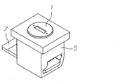
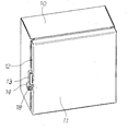
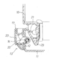
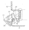
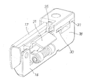
図3に示すように、本発明の電気機器収納用箱は箱本体10と、その前面に蝶番によって支持された扉11とからなり、扉11の側板部12にラッチ装置13が取り付けられている。
As shown in FIG. 3, the electric device storage box of the present invention includes a
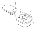
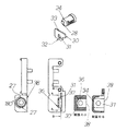
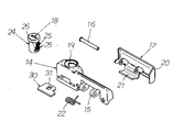
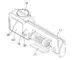
図4、図5に示すように、このラッチ装置13は鋳造された縦長の本体14と、本体14の腕部15にピン16によって枢着されたレバー17と、シリンダ錠18とを備えている。本体14はその長手方向の端部にシリンダ錠収納穴19を備え、その内部にシリンダ錠18が扉11の正面向きに収納されている。このシリンダ錠収納穴19付近の部分の構造については後述する。
As shown in FIGS. 4 and 5, the
レバー17は表面側の操作部20と、裏面側の係止片21とを一体に備えたものであり、ピン16の周囲に配置されたバネ22によって常に係止方向に弾発され、図6に示すように箱本体10に突設された係合金具23と係合するようになっている。係止金具23は傾斜面を備えているので、扉11を閉じると係止片21が傾斜面によってガイドされて箱本体10側の係合金具23に係止して図6の鎖錠状態となる。扉11を開く際には図7のようにレバー17を手前側に操作して係止片21を回転させ、鎖錠を解除する。このようなラッチ装置13の動作は一般のラッチ装置と同様である。
The
次に、図8と図9を参照しつつ、シリンダ錠18とシリンダ錠収納穴19について説明する。
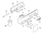
図8に示すように、シリンダ錠18は円柱状のロータ24と、その側面に形成されたスリットを出入りするタンブラー25及びストッパプレート26を主要部品としている。タンブラー25は鍵を挿入するとロータ24の内部に収納されるが、ストッパプレート26は抜け止め用の部材であるから、鍵を挿入しても突出したままである。
Next, the
As shown in FIG. 8, the
本発明ではシリンダ錠18のロータ24が本体14のシリンダ錠収納穴19内に収納される。図9に示すようにシリンダ錠収納穴19の周壁には突出したタンブラー25の先端を収納するスロット27が180°回転位置に形成されている。これは施錠位置および開錠位置に対応する。
In the present invention, the
ロータ24の底面には偏心位置に突起28が設けられている。またロータ24の底面側には、ロックプレート30が設けられている。ロックプレート30はシリンダ錠収納穴19の下部に形成された穴部31内に収納されている。突起28はロックプレート30の長円形の孔31に嵌合されており、シリンダ錠18に鍵を挿入してロータ24を回転させることによって、ロックプレート30は直線部32,33に沿って直線的にスライドする。
A
ここでロックプレート30の直線部32は穴部31の側壁34に接触し、ロックプレート30の直線部33は扉11の側板部12に接触して直線方向のガイドがなされる。そしてロックプレート30がシリンダ錠18から離れる方向にスライドすると、図10に示すようにロックプレート30の先端部がラッチ装置13のレバー17の側部の切欠き35に係合し、レバー17を動かないようにロックする。この構造によって、扉11を閉じた状態で確実にロックすることができる。
Here, the
なお、シリンダ錠18のストッパプレート26はロータ24から常時突出している。このため、図11に示すようにシリンダ錠収納穴19の下部に形成された別の穴部36にストッパプレート26を挿入しておけば、シリンダ錠18の抜け止めとなる。またこの穴部36を図9のAーA断面図の形状としておけば、ロータ24の回転に伴ってストッパプレート26が内壁37に当たることによって、ロータ24の回転角度の規制が可能となる。
Note that the
本発明ではこれらの穴部31、36が本体14の側面38に開口している。このため、本体14の鋳造時に穴部成形用の金型を片側から引抜く構造とすればよく、複雑な構造の金型を必要とせず、製作コストを引き下げることができる利点がある。
In the present invention, these
なお、上記したようにロックプレート30を扉11の側板部12に接触させてスライドさせると、扉11の側板部12に疵が付いたり錆の発生につながることが懸念される。しかし図12に示すように本体14の側面または扉11の側板部12にロックプレート39がスライドする部分を覆う穴塞ぎ部材40を設けておくことにより、この懸念を解消することができる。
In addition, when the
穴塞ぎ部材40としては粘着テープを用いることができる。粘着テープは表面に対して垂直方向には強い接着力を発揮するが、表面と平行な方向の剪断力には弱いという特性があるため、粘着面がロックプレート30に面していてもロックプレート30の作動に支障が生ずることはない。
An adhesive tape can be used as the
以上に説明したように、本発明によればラッチ装置13の長手方向の側方にシリンダ錠18を配置したので、小型化を図ることができ、またその金型構造も簡素化することができる。またラッチ装置13が扉11の側板部に取付けられているにもかかわらず、シリンダ錠18を扉正面向きに配置したので、扉11のロック操作やアンロック操作を行い易い利点がある。
As described above, according to the present invention, the
1 シリンダ錠
2 止め金
3 相手部材
4 係合溝
5 本体
6 外周壁
7 ロックプレート
10 箱本体
11 扉
12 側板部
13 ラッチ装置
14 本体
15 腕部
16 ピン
17 レバー
18 シリンダ錠
19 シリンダ錠収納穴
20 操作部
21 係止片
22 バネ
23 係合金具
24 ロータ
25 タンブラー
26 ストッパプレート
27 スロット
28 突起
30 ロックプレート
31 穴部
32 直線部
33 直線部
34 側壁
35 切欠き
36 穴部
37 内壁
38 本体の側面
40 穴塞ぎ部材
DESCRIPTION OF
Claims (5)
Priority Applications (1)
| Application Number | Priority Date | Filing Date | Title |
|---|---|---|---|
| JP2008260346A JP5268547B2 (en) | 2008-10-07 | 2008-10-07 | Electrical equipment storage box |
Applications Claiming Priority (1)
| Application Number | Priority Date | Filing Date | Title |
|---|---|---|---|
| JP2008260346A JP5268547B2 (en) | 2008-10-07 | 2008-10-07 | Electrical equipment storage box |
Publications (2)
| Publication Number | Publication Date |
|---|---|
| JP2010090579A true JP2010090579A (en) | 2010-04-22 |
| JP5268547B2 JP5268547B2 (en) | 2013-08-21 |
Family
ID=42253555
Family Applications (1)
| Application Number | Title | Priority Date | Filing Date |
|---|---|---|---|
| JP2008260346A Active JP5268547B2 (en) | 2008-10-07 | 2008-10-07 | Electrical equipment storage box |
Country Status (1)
| Country | Link |
|---|---|
| JP (1) | JP5268547B2 (en) |
Cited By (1)
| Publication number | Priority date | Publication date | Assignee | Title |
|---|---|---|---|---|
| JP2013115082A (en) * | 2011-11-25 | 2013-06-10 | Nitto Kogyo Co Ltd | Support medium of housing for storing electric apparatus |
Citations (2)
| Publication number | Priority date | Publication date | Assignee | Title |
|---|---|---|---|---|
| JPH0624171U (en) * | 1992-08-31 | 1994-03-29 | 加藤発条株式会社 | Lid locking device |
| JP2008121208A (en) * | 2006-11-09 | 2008-05-29 | Nitto Electric Works Ltd | Door locking device of cabinet for housing electric and electronic devices |
-
2008
- 2008-10-07 JP JP2008260346A patent/JP5268547B2/en active Active
Patent Citations (2)
| Publication number | Priority date | Publication date | Assignee | Title |
|---|---|---|---|---|
| JPH0624171U (en) * | 1992-08-31 | 1994-03-29 | 加藤発条株式会社 | Lid locking device |
| JP2008121208A (en) * | 2006-11-09 | 2008-05-29 | Nitto Electric Works Ltd | Door locking device of cabinet for housing electric and electronic devices |
Cited By (1)
| Publication number | Priority date | Publication date | Assignee | Title |
|---|---|---|---|---|
| JP2013115082A (en) * | 2011-11-25 | 2013-06-10 | Nitto Kogyo Co Ltd | Support medium of housing for storing electric apparatus |
Also Published As
| Publication number | Publication date |
|---|---|
| JP5268547B2 (en) | 2013-08-21 |
Similar Documents
| Publication | Publication Date | Title |
|---|---|---|
| TWI391273B (en) | Cylinder lock protect apparatus | |
| JP2009180028A (en) | Opening/closing lock device | |
| JP5268547B2 (en) | Electrical equipment storage box | |
| JP4173400B2 (en) | Locking device for opening / closing member | |
| JP4678346B2 (en) | External operation handle of the switch | |
| JP4127712B2 (en) | Lock handle device for door | |
| JP4518900B2 (en) | Lid opening / closing device | |
| JP4418020B1 (en) | Locking device | |
| JP2001311330A (en) | Lock device using magnet | |
| JP4850608B2 (en) | Cylinder lock | |
| JP5262298B2 (en) | Power supply | |
| JP4698369B2 (en) | Latch lock | |
| JP6148047B2 (en) | Vehicle lock unit | |
| JP4917370B2 (en) | Electrical equipment storage box | |
| JP7055405B2 (en) | Concealed door locks and concealed doors | |
| JP7057136B2 (en) | Latch lock for delivery box | |
| CN115341814B (en) | Magnetic fastening device | |
| JP2004211369A (en) | Crescent | |
| JP4228921B2 (en) | Latch lock | |
| JP5965710B2 (en) | Vehicle door handle device | |
| JP2006249861A (en) | Combination lock | |
| JP2008121208A (en) | Door locking device of cabinet for housing electric and electronic devices | |
| JP6418389B2 (en) | Latch holder | |
| JP4849615B2 (en) | Door locking device for cabinet for storing electrical and electronic equipment | |
| JP6023995B2 (en) | Lock structure of electrical equipment storage box using cylinder lock |
Legal Events
| Date | Code | Title | Description |
|---|---|---|---|
| A621 | Written request for application examination |
Free format text: JAPANESE INTERMEDIATE CODE: A621 Effective date: 20110824 |
|
| A977 | Report on retrieval |
Free format text: JAPANESE INTERMEDIATE CODE: A971007 Effective date: 20121031 |
|
| A131 | Notification of reasons for refusal |
Free format text: JAPANESE INTERMEDIATE CODE: A131 Effective date: 20121106 |
|
| A521 | Written amendment |
Free format text: JAPANESE INTERMEDIATE CODE: A523 Effective date: 20121218 |
|
| TRDD | Decision of grant or rejection written | ||
| A01 | Written decision to grant a patent or to grant a registration (utility model) |
Free format text: JAPANESE INTERMEDIATE CODE: A01 Effective date: 20130507 |
|
| A61 | First payment of annual fees (during grant procedure) |
Free format text: JAPANESE INTERMEDIATE CODE: A61 Effective date: 20130507 |
|
| R150 | Certificate of patent or registration of utility model |
Ref document number: 5268547 Country of ref document: JP Free format text: JAPANESE INTERMEDIATE CODE: R150 Free format text: JAPANESE INTERMEDIATE CODE: R150 |