JP2010089754A - Roof structure for vehicle body - Google Patents
Roof structure for vehicle body Download PDFInfo
- Publication number
- JP2010089754A JP2010089754A JP2008264466A JP2008264466A JP2010089754A JP 2010089754 A JP2010089754 A JP 2010089754A JP 2008264466 A JP2008264466 A JP 2008264466A JP 2008264466 A JP2008264466 A JP 2008264466A JP 2010089754 A JP2010089754 A JP 2010089754A
- Authority
- JP
- Japan
- Prior art keywords
- roof
- vehicle body
- crossbow
- bow
- side roof
- Prior art date
- Legal status (The legal status is an assumption and is not a legal conclusion. Google has not performed a legal analysis and makes no representation as to the accuracy of the status listed.)
- Withdrawn
Links
Images


Abstract
Description
本発明は、例えば大型バス等の車両のルーフ部に適用される車体の屋根構造に関する。 The present invention relates to a roof structure of a vehicle body applied to a roof portion of a vehicle such as a large bus.
従来の屋根構造の一例が特許文献1に開示されている。特許文献1の屋根構造は、車体の前後方向に延びる閉断面構造のルーフレールと、車体の幅方向に延びるハット形断面のルーフボウと、ピラーの上部に配置されたハット形断面のガゼット(サイドルーフクロスボウ)とを有している。前記ルーフボウは、前記ガゼットを介して、前記ルーフレールに溶接によって結合されている。 An example of a conventional roof structure is disclosed in Patent Document 1. The roof structure of Patent Document 1 includes a roof rail having a closed cross-sectional structure extending in the front-rear direction of the vehicle body, a roof bow having a hat-shaped cross section extending in the width direction of the vehicle body, and a gusset having a hat-shaped cross section disposed on the top of the pillar (side roof crossbow). ). The roof bow is joined to the roof rail by welding via the gusset.
例えば大型観光バスでは乗客の見晴らしを良くするために、客室の床面を高くしたいわゆるハイデッカー車(high deck body)が採用されることがある。しかし床面位置が高くなると、天井が高くなり、車両重心位置も高くなるなど、走行安定性に影響が生じることが考えられる。そのため車体を軽くして車体の剛性を大きくし、コスト低減を図るために、車体の骨格部材に角パイプが使用されている。 For example, in a large sightseeing bus, a so-called high deck body with a raised floor surface is sometimes used to improve the view of passengers. However, when the floor surface position becomes high, it is conceivable that the running stability is affected, for example, the ceiling becomes high and the position of the center of gravity of the vehicle also becomes high. Therefore, in order to lighten the vehicle body, increase the rigidity of the vehicle body, and reduce costs, square pipes are used for the skeleton members of the vehicle body.
例えば図8に示されるように、車体前後方向に延びる左右一対のサイドルーフレール1(一方のみ示す)と、これらサイドルーフレール1間に配置されたルーフボウ2とを有する屋根構造が知られている。この屋根構造においては、車体がねじれた際にルーフボウ2の結合部に大きな応力が発生するのを防止するために、サイドルーフレール1とルーフボウ2との間に、角パイプからなるルーフレール3が設けられている。そしてサイドルーフレール1とルーフレール3とを、サイドルーフクロスボウ4を介して互いに溶接部5によって連結し、ルーフ部の車体幅方向の側部の剛性を大きくすることにより、ルーフ部の変形量を小さくしている。
特許文献1の屋根構造は、ハイデッカー車のようにルーフ部の高さが大きい車両の場合にルーフ部の剛性が不足することがある。図8に示された従来の屋根構造は、重量が大きく、しかも溶接部が多数存在するため、ルーフ部を組立てる際の作業の負担が大きい。 In the roof structure of Patent Document 1, the rigidity of the roof portion may be insufficient when the vehicle has a large roof portion, such as a high decker vehicle. The conventional roof structure shown in FIG. 8 is heavy and has a large number of welds, so that the work load when assembling the roof part is large.
従って本発明の目的は、ルーフ部の剛性が大きくかつ軽量に構成することができる車体の屋根構造を提供することにある。 Accordingly, it is an object of the present invention to provide a roof structure for a vehicle body that can be configured to have a lightweight and lightweight roof portion.
本発明の車体の屋根構造は、車体のルーフ部の両側部に車体前後方向に延在し、それぞれが矩形の閉断面構造をなすパイプ状の左右一対のサイドルーフレールと、前記一対のサイドルーフレール間で車体幅方向に延在し、車体前後方向に間隔をなして複数配設され、それぞれが閉断面構造をなしかつ車体幅方向に向けて開口する開口端を有するパイプ状のルーフボウと、前記ルーフボウと前記サイドルーフレールとの間に車体前後方向から見て湾曲した形状をなして配置されたサイドルーフクロスボウとを備えている。このサイドルーフクロスボウは、車体側方から見て上部側の一端から下部側の他端に向って扇形に広がる形状でかつ閉断面構造をなし、前記一端が前記ルーフボウの前記開口端に嵌合した状態で固定され、前記他端が前記サイドルーフレールに固定されている。 The roof structure of the vehicle body according to the present invention includes a pair of left and right pipe-shaped side roof rails extending in the longitudinal direction of the vehicle body on both sides of the roof portion of the vehicle body, each having a rectangular closed cross-sectional structure, and the pair of side roof rails. A pipe-shaped roof bow that extends in the vehicle body width direction and is disposed at intervals in the vehicle body longitudinal direction, each having a closed cross-sectional structure and having an opening end that opens in the vehicle body width direction, and the roof bow And a side roof crossbow disposed in a curved shape when viewed from the front-rear direction of the vehicle body. This side roof crossbow has a shape that expands in a fan shape from one end on the upper side to the other end on the lower side when viewed from the side of the vehicle body and has a closed cross-sectional structure, and the one end is fitted to the opening end of the roof bow The other end is fixed to the side roof rail.
本発明の好ましい形態では、前記サイドルーフクロスボウの前記他端の下縁が、前記サイドルーフレールの上面に、車体幅方向のほぼ全域にわたり溶接されている。
また前記サイドルーフクロスボウは、車体前後方向に沿う断面がハット形断面をなし車体前後方向の両側にフランジ部を有するクロスボウ本体と、前記クロスボウ本体の下面側に重ね合わせて固定することにより前記クロスボウ本体の前記ハット形断面の開口を閉塞する補強プレートとを有し、前記補強プレートの車体前後方向の幅が前記クロスボウ本体の車体前後方向の幅よりも大きく、前記補強プレートの車体前後方向の両側に前記フランジ部から突出する張出し部を有し、前記補強プレートの上部に、前記ルーフボウの下面を重ねて固定する第1接合しろを有するとともに、前記補強プレートの下部を前記サイドルーフレールの車体幅方向の内側の面に重ねて固定する第2接合しろを有していてもよい。
In a preferred embodiment of the present invention, the lower edge of the other end of the side roof crossbow is welded to the upper surface of the side roof rail over substantially the entire region in the vehicle body width direction.
The side roof crossbow includes a crossbow body having a hat-shaped cross section in the longitudinal direction of the vehicle body and flange portions on both sides in the longitudinal direction of the vehicle body, and the crossbow body is fixed by overlapping the lower surface side of the crossbow body. A reinforcing plate that closes the opening of the hat-shaped cross section, and the width of the reinforcing plate in the longitudinal direction of the vehicle body is larger than the width of the crossbow body in the longitudinal direction of the vehicle body, and on both sides of the reinforcing plate in the longitudinal direction of the vehicle body. A projecting portion projecting from the flange portion; and a first joining margin for fixing the lower surface of the roof bow on top of the reinforcing plate, and a lower portion of the reinforcing plate in the vehicle width direction of the side roof rail. You may have the 2nd joining margin which overlaps and fixes to an inner surface.
請求項1の屋根構造によれば、車体のルーフ部に入力するねじれ等に対する剛性を扇形のサイドルーフクロスボウによって大きくすることができるため、車体が変形したり、ルーフ部に振動が発生したりすることを抑制できる。またルーフ部の溶接箇所が減るため、車体を組立てる際に必要な溶接作業が軽減される。またサイドルーフクロスボウの一端がルーフボウの開口端と嵌合した状態で両者が直接結合されるため、従来のようにサイドルーフクロスボウとルーフボウとを角パイプからなるルーフレールを介して間接的に結合していた場合と比較して、ルーフ部の軽量化が可能となる。 According to the roof structure of claim 1, the rigidity against torsion or the like input to the roof portion of the vehicle body can be increased by the fan-shaped side roof crossbow, so that the vehicle body is deformed or vibration is generated in the roof portion. This can be suppressed. Further, since the number of welded portions of the roof portion is reduced, the welding work necessary for assembling the vehicle body is reduced. In addition, since one end of the side roof crossbow is directly coupled with the open end of the roofbow, the side roof crossbow and the roofbow are indirectly coupled via a roof rail made of a square pipe as in the past. Compared to the case, the weight of the roof portion can be reduced.
請求項2の屋根構造によれば、車体がねじれた際、あるいは上下方向の負荷が入力した際に、サイドルーフクロスボウとサイドルーフレールとの結合部に作用する負荷を前記サイドルーフクロスボウの下縁の車体幅方向に沿う溶接部を介して、サイドルーフクロスボウが受けることになる。前記結合部に作用する負荷は上下方向が大部分であるため、上下方向の負荷に対して前記結合部の応力を低減させることができる。
According to the roof structure of
請求項3の屋根構造によれば、ルーフボウとサイドルーフクロスボウとを溶接する際、前記第1接合しろによって、ルーフボウとサイドルーフクロスボウとの上下方向の位置決めをなすことができる。また、サイドルーフクロスボウをサイドルーフレールに溶接する際、前記第2接合しろによって、サイドルーフレールに対するサイドルーフクロスボウの車体幅方向の位置決めをなすことができるため、サイドルーフクロスボウの取付け位置の精度が向上する。さらに第1接合しろをルーフボウに溶接し、かつ、第2接合しろをサイドルーフレールに溶接することによって、ルーフボウとサイドルーフクロスボウとの結合部およびサイドルーフレールとサイドルーフクロスボウとの結合部の剛性を高めることができる。 According to the roof structure of the third aspect, when the roof bow and the side roof crossbow are welded, the roof bow and the side roof crossbow can be positioned in the vertical direction by the first joining margin. Further, when the side roof crossbow is welded to the side roof rail, the side roof crossbow can be positioned with respect to the side roof rail in the vehicle width direction by the second joining margin, so that the accuracy of the mounting position of the side roof crossbow is improved. . Further, by welding the first joining margin to the roof bow and welding the second joining margin to the side roof rail, the rigidity of the joint portion between the roof bow and the side roof crossbow and the joint portion between the side roof rail and the side roof crossbow is increased. be able to.
以下に本発明の1つの実施形態に係る屋根構造について、図1から図7を参照して説明する。
図1は、車両10の一例として大型バスを示している。この車両10の車体11の上部に、本発明に係る屋根構造を備えたルーフ部12が設けられている。ルーフ部12は、骨組構体13と、骨組構体13の外側に設けられたルーフパネル14などによって構成されている。
Hereinafter, a roof structure according to one embodiment of the present invention will be described with reference to FIGS. 1 to 7.
FIG. 1 shows a large bus as an example of the
図2は、ルーフ部12を構成する骨組構体13の一部を示している。骨組構体13は、車体11の前後方向に延在する左右一対のサイドルーフレール20,21と、上下方向に延びる複数のウインドピラー22を含んでいる。サイドルーフレール20,21は、車体11の両側部に設けられ、それぞれが矩形断面の金属パイプからなり、閉断面構造をなしている。
FIG. 2 shows a part of the
車体11の一方の側部に設けられたウインドピラー22の上端は、一方のサイドルーフレール20に結合されている。車体11の他方の側部に設けられたウインドピラー22の上端は、他方のサイドルーフレール21に結合されている。
The upper end of the
サイドルーフレール20,21間に、互いにサイズが異なる2種類のルーフボウユニット31,32が車体11の前後方向(図2に矢印Xで示す方向)に間隔をなして交互に配置されている。これら2種類のルーフボウユニット31,32は、車体11の幅方向(図2に矢印Yで示す方向)に延びている。これ以降、矢印Xで示す方向を車体前後方向と呼び、矢印Yで示す方向を車体幅方向と呼ぶ。ルーフボウユニット31,32間に、車体前後方向に延びる複数のスティフナ(stiffener)35が配置されている。
Two types of
前記2種類のルーフボウユニット31,32のうち一方のルーフボウユニット31は、サイドルーフレール20,21のウインドピラー22が設けられていない個所において、サイドルーフレール20,21の上面側に配置されている。これ以降、一方のルーフボウユニット31を第1のルーフボウユニットと呼ぶ。図3から図6に第1のルーフボウユニット31が示されている。
One
前記2種類のルーフボウユニット31,32のうち他方のルーフボウユニット32は、サイドルーフレール20,21のウインドピラー22が設けられている個所、すなわち大きな剛性が必要とされる箇所において、サイドルーフレール20,21の上面側に配置されている。これ以降、このルーフボウユニット32を第2のルーフボウユニットと呼ぶ。図7は第2のルーフボウユニット32を示している。
Of the two types of
第1のルーフボウユニット31と第2のルーフボウユニット32のそれぞれの一方の端部が、一方のサイドルーフレール20に結合されている。ルーフボウユニット31,32のそれぞれの他方の端部が、他方のサイドルーフレール21に結合されている。
One end of each of the first
以下に、車体11の一方の側部におけるサイドルーフレール20とルーフボウユニット31,32との結合部について説明する。なお、車体11の他方の側部におけるサイドルーフレール21とルーフボウユニット31,32との結合部も同様に構成されているため説明は省略する。
Below, the coupling | bond part of the
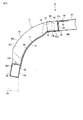
図3から図6に示されるように、第1のルーフボウユニット31は、第1のルーフボウ40と、第1のサイドルーフクロスボウ41とによって構成されている。第1のルーフボウ40はパイプ状をなし、車体幅方向に延びている。このルーフボウ40は、矩形断面の金属パイプ、例えば一辺の長さW1が40mmの断面ほぼ正方形の角パイプからなり、上面壁40aと、前面壁40bと、後面壁40cと、下面壁40dとを有し、閉断面構造をなしている。
As shown in FIGS. 3 to 6, the first
図4に示すように第1のルーフボウ40の端部に、車体幅方向に向けて開口する開口端45が形成されている。また第1のルーフボウ40の前面壁40bと後面壁40cに、それぞれ断面がL形のブラケット48が溶接によって固定されている。
As shown in FIG. 4, an
図5に示すように、第1のサイドルーフクロスボウ41は、車体前後方向から見て、サイドルーフレール20と第1のルーフボウ40との間で外側に凸の円弧を描くように湾曲した形状をなしている。第1のサイドルーフクロスボウ41は、プレスによって成形されたハット形断面のクロスボウ本体50と、補強プレート51とによって構成されている。
As shown in FIG. 5, the first
クロスボウ本体50は、車体11の側方から見て、上部側の一端から下部側の他端に向って、扇形に広がる形状をなしている。クロスボウ本体50の車体前後方向の幅W2(図2と図6に示す)は、ルーフボウ40の幅W1よりも大きい。クロスボウ本体50は、車体前後方向に沿う断面がハット形断面をなし、図6に示すように、前側壁50aと、後側壁50bと、外側壁50cと、前後方向の両側(前縁と後縁)に形成されたフランジ部55などを有している。
The crossbow
補強プレート51は、図5に示すように車体前後方向から見て、クロスボウ本体50に応じて湾曲した形状に成形されている。この補強プレート51は、クロスボウ本体50の前記ハット形断面の開口を閉塞することができる大きさを有している。補強プレート51をクロスボウ本体50のフランジ部55に重ね合わせ、両者を溶接によって接合することにより、クロスボウ本体50と補強プレート51とによって閉断面が構成されている。図3中の符号P1は、その溶接部の一例を示している。
As shown in FIG. 5, the reinforcing
クロスボウ本体50の上部側の一端に、第1のルーフボウ40の開口端45に嵌合可能な大きさの挿入部60が形成されている。挿入部60は、前壁61と、後壁62と、上壁63とを有し、下面側が開口した形状をなしている。この挿入部60を第1のルーフボウ40の開口端45に挿入し、開口端45の周囲を溶接することにより、第1のサイドルーフクロスボウ41の上部側が第1のルーフボウ40に固定されている。図3中の符号P2は、その溶接部の一例を示している。なお、第1のルーフボウ40の開口端45をクロスボウ本体50の挿入部60の内側に挿入するように構成してもよい。要するに、第1のサイドルーフクロスボウ41の上部側の一端を第1のルーフボウ40の開口端45に嵌合させた状態で両者が固定されていればよい。
At one end on the upper side of the crossbow
このように第1のサイドルーフクロスボウ41を第1のルーフボウ40に結合することなどにより、第1のルーフボウユニット31が予め製作(サブアッシー)されたのち、第1のルーフボウユニット31がサイドルーフレール20,21に結合される。
Thus, after the first
補強プレート51の車体前後方向の幅W3(図6に示す)は、クロスボウ本体50の車体前後方向の幅W2よりも大きい。補強プレート51の車体前後方向の両側(前縁部と後縁部)に、それぞれ張出し部70が形成されている。張出し部70は、クロスボウ本体50のフランジ部55に対して、車体前後方向に突出している。またこの補強プレート51には、曲げ剛性を高めるために上下方向に沿うリブ71が形成されている。
The width W3 (shown in FIG. 6) of the reinforcing
補強プレート51の上部側の一端に、第1接合しろ75が形成されている。この第1接合しろ75の上方から第1のルーフボウ40の端部の下面壁40dを重ね、第1接合しろ75とルーフボウ40の端部とが溶接されている。図3中の符号P3は、その溶接部の一例を示している。
A first joining
補強プレート51の下部側の他端には、サイドルーフレール20の車体幅方向の内側の面20aに重ねて固定される第2接合しろ76が形成されている。第2接合しろ76は、クロスボウ本体50の下縁50dの下方に突出している。第2接合しろ76をサイドルーフレール20の内側の面20aに当接させるとともに、クロスボウ本体50の下縁50dをサイドルーフレール20の上面20bに当接させることにより、サイドルーフレール20に対するサイドルーフクロスボウ41の位置決めをなすことができる。
A second joining
このようにサイドルーフレール20とサイドルーフクロスボウ41との位置決めがなされた状態のもとで、クロスボウ本体50の下縁50dとサイドルーフレール20の上面20bとを溶接によって結合することにより、クロスボウ本体50とサイドルーフレール20とが互いに結合されている。図3中の符号P4は、その溶接部の一例を示している。溶接部P4は、クロスボウ本体50の下縁50dの車体前後方向の全長と、サイドルーフレール20の上面20bの車体幅方向のほぼ全域にわたっている。第2接合しろ76は、サイドルーフレール20の内側の面20aに車体前後方向のほぼ全域にわたって溶接されている。
With the
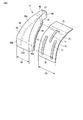
図7に示された第2のルーフボウユニット32は、前記第1のルーフボウユニット31と比較してサイズが大きい点を除き、基本的な構成は第1のルーフボウユニット31と共通である。
The basic structure of the second
第2のルーフボウユニット32は、第2のルーフボウ80と、第2のサイドルーフクロスボウ81とによって構成されている。第2のルーフボウ80はパイプ状をなし、車体幅方向に延びている。第2のルーフボウユニット32は、第1のルーフボウ40よりも外形寸法の大きい矩形断面の金属パイプによって構成されている。例えば第2のルーフボウ80は一辺の長さW5が50mmの断面ほぼ正方形の角パイプからなり、上面壁80aと、前面壁80bと、後面壁80cと、下面壁80dとを有している。
The second
第2のルーフボウ80の端部に、車体幅方向に向けて開口する開口端85が形成されている。また第2のルーフボウ80の前面壁80bと後面壁80cに、それぞれ断面がL形のブラケット88が溶接によって固定されている。
An opening
第2のサイドルーフクロスボウ81は、車体前後方向から見て、サイドルーフレール20と第2のルーフボウ80との間で外側に凸の円弧を描くように湾曲した形状をなしている。第2のサイドルーフクロスボウ81は、プレスによって成形されたハット形断面のクロスボウ本体90と、補強プレート91とによって構成されている。
The second
クロスボウ本体90は、車体11の側方から見て、上部側の一端から下部側の他端に向って扇形に広がる形状をなしている。クロスボウ本体90の車体前後方向の幅W6(図7に示す)は、第1のサイドルーフクロスボウ41のクロスボウ本体50の幅W2(図2と図6に示す)よりも大きい。クロスボウ本体90は、車体前後方向に沿う断面がハット形断面をなし、前側壁90aと、後側壁90bと、外側壁90cと、前後方向の両側(前縁と後縁)に形成されたフランジ部95などを有している。
When viewed from the side of the vehicle body 11, the
補強プレート91は、車体前後方向から見て、クロスボウ本体90に応じて湾曲した形状に成形されている。この補強プレート91は、クロスボウ本体90の前記ハット形断面の開口を閉塞することができる大きさを有している。補強プレート91をクロスボウ本体90のフランジ部95に重ね合わせ、両者を溶接によって接合することにより、クロスボウ本体90と補強プレート91とによって閉断面が構成されている。図7中の符号P5は、その溶接部の一例を示している。
The reinforcing
クロスボウ本体90の上部側の一端に、第2のルーフボウ80の開口端85に嵌合可能な大きさの挿入部100が形成されている。挿入部100は、前壁101と、後壁102と、上壁103とを有し、下面側が開口した形状をなしている。この挿入部100を第2のルーフボウ80の開口端85に挿入し、開口端85の周囲を溶接することにより、第2のサイドルーフクロスボウ81の上部側が第2のルーフボウ80に固定されている。図7中の符号P6は、その溶接部の一例を示している。なお、第2のルーフボウ80の開口端85をクロスボウ本体90の挿入部100の内側に挿入するように構成してもよい。要するに、第2のサイドルーフクロスボウ81の上部側の一端を第2のルーフボウ80の開口端85に嵌合させた状態で両者が固定されていればよい。
At one end on the upper side of the crossbow
このように第2のサイドルーフクロスボウ81を第2のルーフボウ80に結合することなどにより、第2のルーフボウユニット32が予め製作(サブアッシー)されたのち、第2のルーフボウユニット32がサイドルーフレール20,21に結合される。
Thus, after the second
補強プレート91の車体前後方向の幅は、クロスボウ本体90の車体前後方向の幅W6よりも大きい。補強プレート91の車体前後方向の両側(前縁部と後縁部)に、それぞれ張出し部110が形成されている。張出し部110は、クロスボウ本体90のフランジ部95に対して、車体前後方向に突出している。またこの補強プレート91には、曲げ剛性を高めるために上下方向に沿うリブ(図示せず)が形成されている。
The width of the reinforcing
補強プレート91の上部側の一端に、第1接合しろ115が形成されている。この第1接合しろ115の上方から第2のルーフボウ80の端部の下面壁80dを重ね、第1接合しろ115とルーフボウ80の端部とが溶接されている。図7中の符号P7は、その溶接部の一例を示している。
A first joining
補強プレート91の下部側の他端には、サイドルーフレール20の車体幅方向の内側の面20aに重ねて固定される第2接合しろ116が形成されている。第2接合しろ116は、クロスボウ本体90の下縁90dの下方に突出している。第2接合しろ116をサイドルーフレール20の内側の面20aに当接させるとともに、クロスボウ本体90の下縁90dをサイドルーフレール20の上面20bに当接させることにより、サイドルーフレール20に対するサイドルーフクロスボウ81の位置決めをなすことができる。
A second joining
このようにサイドルーフレール20とサイドルーフクロスボウ81との位置決めがなされた状態のもとで、クロスボウ本体90の下縁90dとサイドルーフレール20の上面20bとを溶接によって結合することにより、クロスボウ本体90とサイドルーフレール20とが互いに結合されている。図7中の符号P8は、その溶接部の一例を示している。溶接部P8は、クロスボウ本体90の下縁90dの車体前後方向の全長と、サイドルーフレール20の上面20bの車幅方向のほぼ全域にわたっている。第2接合しろ116は、サイドルーフレール20の内側の面20aに車体前後方向のほぼ全域にわたって溶接されている。
With the
以上説明した第1のルーフボウユニット31と、第2のルーフボウユニット32との間に、車体前後方向に延びる複数のスティフナ(stiffener)35が配置されている。スティフナ35は、上フランジ131と、下フランジ132と、上下方向に延びる縦壁133とを備え、いわゆるZ形の断面を有している。図3に示すようにスティフナ35の一方の端部35aは、第1のルーフボウユニット31のブラケット48と、第1のサイドルーフクロスボウ41の張出し部70に固定されている。
Between the first
第1のルーフボウ40は、第2のルーフボウ80よりも各辺のサイズが小さい角パイプからなるため、スティフナ35の一方の端部35aにおいては、下フランジ132が第1のルーフボウ40の下面壁40dの高さと揃うように、一段高い段差部140が形成されている。スティフナ35の上フランジ131をブラケット48の上面に重ね、かつ、下フランジ132を張出し部70の上に重ねる。そして上フランジ131とブラケット48を互いにスポット溶接によって結合し、かつ、下フランジ132の前記段差部140と第2接合しろ76とを互いにスポット溶接することにより、スティフナ35の一方の端部35aが第1のルーフボウユニット31に固定される。
Since the
図7に示すように、スティフナ35の他方の端部35bは、第2のルーフボウユニット32のブラケット88と第2のサイドルーフクロスボウ81の張出し部110に固定されている。第2のルーフボウ80は第1のルーフボウ40よりも一辺のサイズが大きいため、スティフナ35の下フランジ132に前記段差部140を設ける必要はなく、第2のルーフボウ80の下面壁80dと下フランジ132の高さとが揃っている。
As shown in FIG. 7, the
スティフナ35の上フランジ131をブラケット88の上面に重ね、かつ、下フランジ132を張出し部110の上に重ねる。そして上フランジ131とブラケット88を互いにスポット溶接によって結合し、かつ、下フランジ132と第2接合しろ116とを互いにスポット溶接することにより、スティフナ35の他方の端部35bが第2のルーフボウユニット32に固定される。
The
以上説明したように本実施形態のルーフ部12によれば、ルーフボウ40,80の開口端45,85にサイドルーフクロスボウ41,81の挿入部60,100が挿入(嵌合)された状態で、ルーフボウ40,80とサイドルーフクロスボウ41,81とが溶接されるため、ルーフボウ40,80とサイドルーフクロスボウ41,81との結合部の剛性が大きい。このため図8に示す従来例のようなルーフレール3を用いる必要がなく、ルーフボウ40,80とサイドルーフクロスボウ41,81とが直接結合される。よって、従来例と比較して溶接箇所が減少するとともに、溶接品質を確保する上でも有利である。また従来のルーフ部よりも軽量に構成することができる。
As described above, according to the
また、サイドルーフレール20と第1のルーフボウユニット31との結合部(図3)において、第1のサイドルーフクロスボウ41の下縁50dをサイドルーフレール20の上面20bに上方から突き当てるとともに、補強プレート51の第2接合しろ76をサイドルーフレール20の車体内側の面20aに突き当てた状態で、サイドルーフクロスボウ41の下縁50dをサイドルーフレール20に溶接するため、サイドルーフレール20に対してサイドルーフクロスボウ41を正確な位置に結合することができる。
Further, in the joint portion (FIG. 3) between the
同様に第2のルーフボウユニット32とサイドルーフレール20との結合部(図7)において、第2のサイドルーフクロスボウ81の下縁90dをサイドルーフレール20の上面20bに上方から突き当てるとともに、補強プレート91の第2接合しろ116をサイドルーフレール20の車体内側の面20aに突き当てた状態で、サイドルーフクロスボウ81の下縁90dをサイドルーフレール20に溶接するため、サイドルーフレール20に対してサイドルーフクロスボウ81を正確な位置に結合することができる。
Similarly, in the joint portion (FIG. 7) between the second
サイドルーフクロスボウ41,81は、上部側の一端から下部側の他端に向って車体前後方向の幅が扇形に広がる形状であるため、サイドルーフレール20に対するサイドルーフクロスボウ41,81の下縁50d,90dの接合長さを大きくとることができ、接合部の応力を下げる上でも有効である。
The
しかもサイドルーフレール20とサイドルーフクロスボウ41,81の下縁50d,90dとの溶接部P4,P8は、サイドルーフレール20の上面20bの車体幅方向のほぼ全域にわたっている。このため、ウインドピラー22からサイドルーフレール20を介してサイドルーフクロスボウ41,81に入力する下方からの突き上げによる負荷や、ねじれの負荷に対して、サイドルーフレール20とサイドルーフクロスボウ41,81との結合部に作用する応力を下げることができ、ルーフボウ40,80の長手方向中間部にて、ねじれや曲げ等を吸収することができる。
Moreover, the welded portions P4 and P8 between the
このためハイデッカー車のようにルーフ部の高さが大きい車体においてルーフ部の剛性が確保されることにより、ねじれ等の入力に対して強い車体が得られ、振動に対しても良好な特性を得ることができる。 For this reason, the rigidity of the roof portion is ensured in a vehicle body having a large roof portion like a high decker vehicle, so that a vehicle body that is strong against inputs such as torsion can be obtained, and good characteristics against vibration can be obtained. be able to.
なお本発明を実施するに当たって、サイドルーフレール、ルーフボウ、サイドルーフクロスボウをはじめとして、本発明の構成要素の構造及び配置等を適宜に変更して実施できることは言うまでもない。また、車体の態様についても前記実施形態に制約されることはなく、種々に変更して実施することができる。 Needless to say, in carrying out the present invention, the structure and arrangement of the components of the present invention including the side roof rail, the roof bow, and the side roof crossbow can be appropriately changed. Further, the form of the vehicle body is not limited to the above embodiment, and various modifications can be made.
11…車体
12…ルーフ部
20,21…サイドルーフレール
31…第1のルーフボウユニット
32…第2のルーフボウユニット
35…スティフナ
40…第1のルーフボウ
41…第1のサイドルーフクロスボウ
50…クロスボウ本体
51…補強プレート
75…第1接合しろ
76…第2接合しろ
80…第2のルーフボウ
81…第2のサイドルーフクロスボウ
90…クロスボウ本体
91…補強プレート
115…第1接合しろ
116…第2接合しろ
DESCRIPTION OF SYMBOLS 11 ...
Claims (3)
前記一対のサイドルーフレール間で車体幅方向に延在し、車体前後方向に間隔をなして複数配設され、それぞれが閉断面構造をなしかつ車体幅方向に向けて開口する開口端を有するパイプ状のルーフボウと、
前記ルーフボウと前記サイドルーフレールとの間に車体前後方向から見て湾曲した形状をなして配置され、車体側方から見て上部側の一端から下部側の他端に向って扇形に広がる形状でかつ閉断面構造をなし、前記一端が前記ルーフボウの前記開口端と嵌合した状態で固定され、前記他端が前記サイドルーフレールに固定されたサイドルーフクロスボウと、
を具備したことを特徴とする車体の屋根構造。 A pair of left and right pipe-shaped side roof rails extending in the longitudinal direction of the vehicle body on both sides of the roof portion of the vehicle body, each having a rectangular closed cross-sectional structure;
A plurality of pipes extending in the vehicle body width direction between the pair of side roof rails and arranged at intervals in the vehicle body front-rear direction, each having a closed cross-sectional structure and having an opening end that opens in the vehicle body width direction. And the roof bow,
Between the roof bow and the side roof rail is arranged in a curved shape when viewed from the front-rear direction of the vehicle body, and when viewed from the side of the vehicle body, the shape extends in a fan shape from one end on the upper side to the other end on the lower side, and A side roof crossbow having a closed cross-sectional structure, wherein the one end is fixed in a state of being fitted to the opening end of the roof bow, and the other end is fixed to the side roof rail;
A roof structure of a vehicle body characterized by comprising:
車体前後方向に沿う断面がハット形断面をなし車体前後方向の両側にフランジ部を有するクロスボウ本体と、
前記クロスボウ本体の下面側に重ね合わせて固定することにより前記クロスボウ本体の前記ハット形断面の開口を閉塞する補強プレートとを有し、
前記補強プレートの車体前後方向の幅が前記クロスボウ本体の車体前後方向の幅よりも大きく、前記補強プレートの車体前後方向の両側に前記フランジ部から突出する張出し部を有し、前記補強プレートの上部に、前記ルーフボウの下面を重ねて固定する第1接合しろを有するとともに、前記補強プレートの下部を前記サイドルーフレールの車体幅方向の内側の面に重ねて固定する第2接合しろを有することを特徴とする請求項1または2に記載の車体の屋根構造。 The side roof crossbow is
A crossbow body having a hat-shaped cross section along the vehicle longitudinal direction and having flange portions on both sides in the vehicle longitudinal direction;
A reinforcing plate that closes the opening of the cross section of the crossbow body by overlapping and fixing on the lower surface side of the crossbow body,
The width of the reinforcing plate in the longitudinal direction of the vehicle body is larger than the width of the crossbow body in the longitudinal direction of the vehicle body, and has a projecting portion protruding from the flange portion on both sides of the reinforcing plate in the longitudinal direction of the vehicle body. And having a first joining margin for fixing the lower surface of the roof bow in an overlapping manner, and a second joining margin for fixing the lower portion of the reinforcing plate to the inner surface of the side roof rail in the vehicle width direction. The roof structure of a vehicle body according to claim 1 or 2.
Priority Applications (1)
| Application Number | Priority Date | Filing Date | Title |
|---|---|---|---|
| JP2008264466A JP2010089754A (en) | 2008-10-10 | 2008-10-10 | Roof structure for vehicle body |
Applications Claiming Priority (1)
| Application Number | Priority Date | Filing Date | Title |
|---|---|---|---|
| JP2008264466A JP2010089754A (en) | 2008-10-10 | 2008-10-10 | Roof structure for vehicle body |
Publications (1)
| Publication Number | Publication Date |
|---|---|
| JP2010089754A true JP2010089754A (en) | 2010-04-22 |
Family
ID=42252898
Family Applications (1)
| Application Number | Title | Priority Date | Filing Date |
|---|---|---|---|
| JP2008264466A Withdrawn JP2010089754A (en) | 2008-10-10 | 2008-10-10 | Roof structure for vehicle body |
Country Status (1)
| Country | Link |
|---|---|
| JP (1) | JP2010089754A (en) |
Cited By (7)
| Publication number | Priority date | Publication date | Assignee | Title |
|---|---|---|---|---|
| KR101361385B1 (en) | 2012-11-20 | 2014-02-10 | 기아자동차주식회사 | Front body for low-floor bus |
| JP2015051668A (en) * | 2013-09-05 | 2015-03-19 | いすゞ自動車株式会社 | Vehicle body side frame structure |
| JP2016002922A (en) * | 2014-06-18 | 2016-01-12 | トヨタ車体株式会社 | High-roof vehicle |
| JP2017081196A (en) * | 2015-10-22 | 2017-05-18 | 本田技研工業株式会社 | Vehicle body upper part structure |
| CN108725591A (en) * | 2017-04-21 | 2018-11-02 | 郑州宇通客车股份有限公司 | Vehicle frame structure |
| CN109515523A (en) * | 2017-09-18 | 2019-03-26 | 郑州宇通客车股份有限公司 | Vehicle side wall column, side wall structure and vehicle |
| JP2022013202A (en) * | 2020-07-03 | 2022-01-18 | トヨタ自動車株式会社 | Vehicle with toilet |
-
2008
- 2008-10-10 JP JP2008264466A patent/JP2010089754A/en not_active Withdrawn
Cited By (7)
| Publication number | Priority date | Publication date | Assignee | Title |
|---|---|---|---|---|
| KR101361385B1 (en) | 2012-11-20 | 2014-02-10 | 기아자동차주식회사 | Front body for low-floor bus |
| JP2015051668A (en) * | 2013-09-05 | 2015-03-19 | いすゞ自動車株式会社 | Vehicle body side frame structure |
| JP2016002922A (en) * | 2014-06-18 | 2016-01-12 | トヨタ車体株式会社 | High-roof vehicle |
| JP2017081196A (en) * | 2015-10-22 | 2017-05-18 | 本田技研工業株式会社 | Vehicle body upper part structure |
| CN108725591A (en) * | 2017-04-21 | 2018-11-02 | 郑州宇通客车股份有限公司 | Vehicle frame structure |
| CN109515523A (en) * | 2017-09-18 | 2019-03-26 | 郑州宇通客车股份有限公司 | Vehicle side wall column, side wall structure and vehicle |
| JP2022013202A (en) * | 2020-07-03 | 2022-01-18 | トヨタ自動車株式会社 | Vehicle with toilet |
Similar Documents
| Publication | Publication Date | Title |
|---|---|---|
| US8690227B2 (en) | Lower vehicle-body structure of vehicle | |
| US9555836B2 (en) | Vehicle side structure | |
| JP2010089754A (en) | Roof structure for vehicle body | |
| CN109204576B (en) | Vehicle body structure | |
| EP2186665A1 (en) | Rear door structure | |
| WO2012053080A1 (en) | Vehicle body structure | |
| JP5075949B2 (en) | Body front structure | |
| JP2010228542A (en) | Upper structure of vehicle body | |
| JP2009286331A (en) | Vehicle body skeleton structure | |
| CN109421824B (en) | Vehicle lower structure | |
| EP2412612B1 (en) | Side sill structure for automobile | |
| JP6194915B2 (en) | Vehicle side body structure | |
| WO2016208409A1 (en) | Vehicle body front structure | |
| JP2010089755A (en) | Roof structure for vehicle body | |
| JP2012035646A (en) | Vehicle body lower structure | |
| JP4616015B2 (en) | Triangular window reinforcement structure | |
| JP2015182627A (en) | Panel structure of vehicle body | |
| JP2007055529A (en) | Car body structure | |
| JP2020040502A (en) | Front vehicle body structure for vehicle | |
| JP2007131042A (en) | Getting on-and-off door opening peripheral edge part structure of cab-over vehicle | |
| JP5480324B2 (en) | Car body side structure | |
| CN105966470A (en) | An engine compartment longitudinal beam and a front floor longitudinal beam connecting structure and automobile | |
| JP2002249069A (en) | Front pillar reinforcement structure for vehicle | |
| JP4853164B2 (en) | Body panel joint structure | |
| JP2005212601A (en) | Vehicle body floor structure |
Legal Events
| Date | Code | Title | Description |
|---|---|---|---|
| A300 | Withdrawal of application because of no request for examination |
Free format text: JAPANESE INTERMEDIATE CODE: A300 Effective date: 20120110 |