JP2010087581A - Optical communication system - Google Patents
Optical communication system Download PDFInfo
- Publication number
- JP2010087581A JP2010087581A JP2008251246A JP2008251246A JP2010087581A JP 2010087581 A JP2010087581 A JP 2010087581A JP 2008251246 A JP2008251246 A JP 2008251246A JP 2008251246 A JP2008251246 A JP 2008251246A JP 2010087581 A JP2010087581 A JP 2010087581A
- Authority
- JP
- Japan
- Prior art keywords
- demultiplexer
- input
- optical
- wavelength multiplexer
- optical wavelength
- Prior art date
- Legal status (The legal status is an assumption and is not a legal conclusion. Google has not performed a legal analysis and makes no representation as to the accuracy of the status listed.)
- Granted
Links
Images


Landscapes
- Optical Communication System (AREA)
Abstract
Description
本発明は、光通信システムに関し、より詳細には、光波長多重された複数の信号を用い、信号の波長に応じて信号の経路が定まる光通信システムに関する。 The present invention relates to an optical communication system, and more particularly to an optical communication system that uses a plurality of optical wavelength-multiplexed signals and determines a signal path according to the signal wavelength.
複数の光信号を異なる波長の光に乗せ、1本の光ファイバで伝送する波長分割多重(WDM:Wavelength Division Multiplexing)伝送システムは、伝送路の容量を大幅に増大させることが可能であり、既に基幹系システムを中心に導入が進んでいる。 A wavelength division multiplexing (WDM) transmission system in which a plurality of optical signals are placed on light of different wavelengths and transmitted through a single optical fiber can greatly increase the capacity of the transmission path, Introduction is progressing mainly in mission-critical systems.
さらに近年、光信号の波長を伝送路容量の増大に利用するだけでなく、ネットワークの経路設定に用いる手法の検討も進んでおり、その一例として波長多重信号を送受信する通信ノードと、アレイ導波路回折格子を利用することで、通信ノード間にフルメッシュの接続性を得られる光通信システムがある。 Further, in recent years, not only is the wavelength of an optical signal used to increase the transmission path capacity, but also a study of a method for setting a network path is progressing. As an example, a communication node that transmits and receives wavelength multiplexed signals, and an array waveguide There is an optical communication system that can obtain full mesh connectivity between communication nodes by using a diffraction grating.
図12に波長可変光源とアレイ導波路回折格子を利用した光通信システムの構成を示す。中心にN入力N出力(以下、N×Nと表記する)光波長合分波器201が設置され、複数の通信ノード202との間が、送受2心の光ファイバ203で接続される。尚、本例では、N=4の場合を示す。具体的には、光波長合分波器201の入出力ポート数を4×4とし、送信器と受光素子の数を4とする場合を示す。
FIG. 12 shows the configuration of an optical communication system using a wavelength tunable light source and an arrayed waveguide diffraction grating. An N-input N-output (hereinafter referred to as N × N) optical wavelength multiplexer /
通信ノード202の内部には、光信号の送信に関わる装置として、それぞれ所定の波長の信号を出力する送信器204−1〜204−4と、この送信器204−1〜204−4の出力を入力とする波長合波器205を備える。この波長合波器205の出力は送受2心の光ファイバ203のうちの1本を介して、4×4光波長合分波器201の入力ポートに接続される。同じく、通信ノード202の内部には、光信号の受信に関わる装置として、入力されたWDM信号を波長に応じて定まるポートから出力する波長分波器206と、この波長分波器206の出力を入力とする受光素子207−1〜207−4を備える。波長分波器206の入力は送受2心の光ファイバ203のうちの残りの1本を介して、4×4光波長合分波器201の出力ポートに接続される。
In the
4×4光波長合分波器201として、アレイ導波路回折格子を使用することが出来る。アレイ導波路回折格子は別に設計によって定まる基本周期(FSR:Free Spectral Range)を有しており、これをλFSRとする。このλFSRを踏まえて得られる入出力ポート間の透過特性は、「入力ポートXから入力され、出力ポートYから出力される信号の波長は、その波長がλ(X+Y-1)+Z・λFSRである。ここで、X、Yは1以上N以下の整数。Zは負の数を含む任意の整数。λは等波長間隔あるいは等周波数間隔など所定の間隔で定義された波長。」と定義できる。以降では、特にλを等波長間隔Δλで定義し、λFSR=4・Δλである場合を例に考える。即ち、「入力ポートXから入力され、出力ポートYから出力される信号の波長は、その波長がλ(X+Y-1+4Z)である。」と表せる場合である。
As the 4 × 4 optical wavelength multiplexer /
各通信ノード202では、送信器204−1〜204−4、波長合波器205を用いて、λ1からλ4までの4波長が波長分割多重化された信号を出力するものとする。同様に、各通信ノード202では、波長合波器206、送信器207−1〜207−4を用いて、λ1からλ4までの4波長が波長分割多重化された信号を受信するものとする。
Each
このとき、いずれかの通信ノード202から出力された4波長の波長分割多重化された信号は、通信ノード202が接続されている4×4光波長合分波器201の入力ポートに入力されると、その入出力特性に従って波長毎に異なる出力ポートに出力され、4×4光波長合分波器201の出力ポートに接続されている通信ノード202において波長分波器206で分波され、信号波長に応じて定まる受光素子207−1〜207−4のいずれかで受光される。
At this time, the wavelength division multiplexed signal of 4 wavelengths output from one of the
同様に、全ての通信ノード202から出力された4波長の波長分割多重化された信号の経路を辿ると、フルメッシュの光ファイバを敷設した場合と同じ接続性が得られることが分かる。従って、通信ノード間で大容量のデータを低遅延で送受信することが可能となる。
Similarly, following the path of wavelength-division multiplexed signals of four wavelengths output from all
しかしながら、このような従来技術を用いて実現される光通信システムでは、システムを拡張するために、図13に示すように、波長多重信号を送受信する通信ノードと4×4光波長合分波器からなるシステムを2つ設け、単純に4×4光波長合分波器のポート間を接続しても、全ての通信ノード間にフルメッシュの光ファイバを敷設した場合と同じ接続性を得ることは出来ない。例えば、図13に示すように、第1の4×4光波長合分波器201の第4出力ポートと、第2の4×4光波長合分波器201の第2入力ポートを接続し、第2の4×4光波長合分波器201の第2出力ポートと、第1の4×4光波長合分波器201の第4入力ポートを接続する場合を考える。
However, in such an optical communication system realized by using the conventional technology, as shown in FIG. 13, in order to expand the system, a communication node that transmits and receives wavelength multiplexed signals and a 4 × 4 optical wavelength multiplexer / demultiplexer Even if two 4x4 optical wavelength multiplexer / demultiplexer ports are simply connected, the same connectivity as when full-mesh optical fibers are laid between all communication nodes is obtained. I can't. For example, as shown in FIG. 13, the fourth output port of the first 4 × 4 optical wavelength multiplexer /
このとき、第1の4×4光波長合分波器201の第1入出力ポートに接続された通信ノード202から、λ4、λ8、λ12等のλ(4Z)で表される波長を送出すると、第1の4×4光波長合分波器201の第4出力ポートを経由して、第2の4×4光波長合分波器201の第2入力ポートに入力されるが、全て第2の4×4光波長合分波器201の第3出力ポートから出力され、同じ通信ノード202に届いてしまい、第2の4×4光波長合意分波器201に接続されている他の通信ノードには、信号を送ることができない。
At this time, from the
本発明は、このような課題に鑑みてなされたもので、その目的とするところは、通信ノード間にフルメッシュの接続性を得られる複数の光通信システムが、各光通信システム内の光波長合分波器の入出力ポート間をフルメッシュの接続性を失わないように接続することによって接続された光通信システムを提供することにある。 The present invention has been made in view of such a problem, and an object of the present invention is to provide a plurality of optical communication systems capable of obtaining full mesh connectivity between communication nodes. An object of the present invention is to provide an optical communication system connected by connecting the input / output ports of the multiplexer / demultiplexer so as not to lose the full mesh connectivity.
このような目的を達成するために、請求項1に記載の発明は、1波長の信号又は波長多重信号を送受信する複数の通信ノードと、K個(Kは2以上の整数)の多入力多出力の光波長合分波器を備えた光通信システムであって、所望の整数Cに対して、少なくとも、所定の間隔Δλを有する波長λ1からλCを使用し、基本周期がAk×Δλ(kは1以上K以下の整数、Akは2以上の整数)の第kの多入力多出力の光波長合分波器は、任意の1つの入力ポートに信号が入力されると、任意の隣接する2つの出力ポートからそれぞれ出力される信号の波長はΔλ又はΔλに加えてAk×Δλの整数倍異なり、任意の隣接する2つの入力ポートにそれぞれ信号が入力されると、任意の1つの出力ポートから出力される2つの信号の波長はΔλ又はΔλに加えてAk×Δλの整数倍異なる特性を有し、前記各光波長合分波器の出力ポートと入力ポートのうち、各々少なくとも1つが、それぞれ別の前記光波長合分波器の入力ポートと出力ポートに導波路を介して接続され、その他には前記各通信ノードが導波路を介してそれぞれ接続されていることを特徴とする。
In order to achieve such an object, the invention described in
請求項2に記載の発明は、請求項1に記載の光通信システムにおいて、K個の整数A1、A2、…、Akの内、どの2つの整数も最大公約数が1で互いに素であることを特徴とする。
Invention according to
請求項3に記載の発明は、請求項1に記載の光通信システムにおいて、K個の整数A1、A2、…、Akの内、2つの整数Ai、Aj(i、jは1以上K以下の整数)の最大公約数がDであるとき、第iの多入力多出力の光波長合分波器のD組の出力ポートと入力ポートと、第jの多入力多出力の光波長合分波器のD組の入力ポートと出力ポートが、導波路を介してそれぞれ接続されていることを特徴とする。
The invention according to
請求項4に記載の発明は、請求項1乃至3のいずれかに記載の光通信システムにおいて、前記整数Cは、K個の整数A1、A2、…、Akの内、2つの整数の最小公倍数の最大値であることを特徴とする。
Invention according to
請求項5に記載の発明は、請求項1乃至3のいずれかに記載の光通信システムにおいて、前記整数Cは、K個の整数A1、A2、…、Akの最小公倍数であることを特徴とする。
The invention according to
請求項6に記載の発明は、請求項1乃至5のいずれかに記載の光通信システムにおいて、前記各光波長合分波器の出力ポートと入力ポートは、他の全ての前記光波長合分波器の入力ポートと出力ポートにそれぞれ導波路を介して接続されていることを特徴とする。 According to a sixth aspect of the present invention, in the optical communication system according to any one of the first to fifth aspects, the output port and the input port of each of the optical wavelength multiplexers / demultiplexers are all other optical wavelength multiplexing / demultiplexing units. It is characterized by being connected to the input port and the output port of the waver through waveguides, respectively.
請求項7に記載の発明は、請求項1乃至6のいずれかに記載の光通信システムにおいて、前記光波長合分波器は、アレイ導波路回折格子であることを特徴とする。 According to a seventh aspect of the present invention, in the optical communication system according to any one of the first to sixth aspects, the optical wavelength multiplexer / demultiplexer is an arrayed waveguide diffraction grating.
本発明によれば、通信ノード間にフルメッシュの接続性を得られる複数の光通信システムを、各光通信システム内の光波長合分波器の入出力ポート間をフルメッシュの接続性を失わないように接続することによって接続することが可能になる。 According to the present invention, a plurality of optical communication systems capable of providing full mesh connectivity between communication nodes loses full mesh connectivity between the input and output ports of the optical wavelength multiplexer / demultiplexer in each optical communication system. It becomes possible to connect by connecting so that there is no.
以下、図面を参照しながら本発明の実施形態について詳細に説明する。 Hereinafter, embodiments of the present invention will be described in detail with reference to the drawings.
(実施形態1)
図1に、本発明の実施形態1に係る光通信システムの構成を示し、図2、3に、その入出力ポート間の透過特性を示す。実施形態1は、A×Δλの基本周期を有するN×N光波長合分波器(NはA以下の整数)と、B×Δλの基本周期を有するM×M光波長合分波器(MはB以下の整数)を使用し、特にAとBが互いに素(最大公約数が1)の関係であり、波長λ1からλA×Bが所定の間隔Δλで定義されている場合の光通信システムであるが、図1に示す実施形態1は、A=4、B=3、N=4、M=3の場合を例にとって示す。即ち、波長λ1からλ12が所定の間隔Δλで定義されているものとする。
(Embodiment 1)
FIG. 1 shows a configuration of an optical communication system according to
以下で本発明の原理を説明する。
図1に示す光通信システムは、4×4光波長合分波器101−1、3×3光波長合分波器101−2、通信ノード102、送受2心の光ファイバ103、所定の波長の信号を送出する送信器104−1〜104−12、12×1波長合波器105、1×12波長分波器106、受光素子107−1〜107−12を含む。送信器104の数、波長合波器105の入力ポート数、波長分波器106の出力ポート数、受光素子107の数である12は、A×B、即ち、定義した波長数に相当する。
The principle of the present invention will be described below.
The optical communication system shown in FIG. 1 includes a 4 × 4 optical wavelength multiplexer / demultiplexer 101-1, a 3 × 3 optical wavelength multiplexer / demultiplexer 101-2, a
4×4光波長合分波器101−1と3×3光波長合分波器101−2が設置され、4×4光波長合分波器101−1の第4入出力ポートと、3×3光波長合分波器101−2の第3出入力ポートが、送受2心の光ファイバ103で接続される。4×4光波長合分波器101−1の第4入出力ポートと、3×3光波長合分波器101−2の第3入出力ポート以外の4×4光波長合分波器101−1および3×3光波長合分波器101−2の入出力ポートは、それぞれ通信ノード102と、送受2心の光ファイバ103で接続される。
The 4 × 4 optical wavelength multiplexer / demultiplexer 101-1 and the 3 × 3 optical wavelength multiplexer / demultiplexer 101-2 are installed, the fourth input / output port of the 4 × 4 optical wavelength multiplexer / demultiplexer 101-1 and 3 The third input / output port of the × 3 optical wavelength multiplexer / demultiplexer 101-2 is connected by an
各通信ノード102の内部には、光信号の送信に関わる装置として、所定の波長の信号を送出する送信器104−1〜104−12と、この送信器104−1〜104−12の出力を入力とする波長合波器105を備える。この波長合波器105の出力は、送受2心の光ファイバ103の内の1本を介して、4×4光波長合分波器101−1あるいは3×3光波長合分波器101−2の入力ポートに接続される。同じく、各通信ノード102の内部には、光信号の受信に関わる装置として、入力されたWDM信号を波長に応じて定まるポートから出力する波長分波器106と、この波長分波器106の出力を入力とする受光素子107−1〜107−12を備える。波長分波器106の入力は送受2心の光ファイバ103の内の残りの1本を介して、4×4光波長合分波器101−1あるいは3×3光波長合分波器101−2の出力ポートに接続される。尚、ここでは各通信ノード102の入力と出力は、それぞれ光波長合分波器の同一番号の入出力ポートに接続されているが、必ずしも同一番号の入出力ポートに接続しなくともよい。
In each
4×4光波長合分波器101−1および3×3光波長合分波器101−2として、具体的にはアレイ導波路回折格子を使用する。アレイ導波路回折格子は、占有容積が小さく、多チャンネル化が容易である点で優れている。アレイ導波路回折格子は設計によって定まる基本周期(FSR:Free Spectral Range)を有している。本実施形態においては、(基本周期/Δλ)の値が互いに素(最大公約数が1)である2つの光波長合分波器を使用する。具体的には、基本周期が4×Δλである4×4光波長合分波器101−1および基本周期が3×Δλである3×3光波長合分波器101−2を使用する場合を示す。 Specifically, array waveguide diffraction gratings are used as the 4 × 4 optical wavelength multiplexer / demultiplexer 101-1 and the 3 × 3 optical wavelength multiplexer / demultiplexer 101-2. The arrayed waveguide diffraction grating is excellent in that it occupies a small volume and can be easily multi-channeled. The arrayed waveguide diffraction grating has a fundamental period (FSR: Free Spectral Range) determined by design. In this embodiment, two optical wavelength multiplexers / demultiplexers in which the values of (fundamental period / Δλ) are relatively prime (the greatest common divisor is 1) are used. Specifically, when using a 4 × 4 optical wavelength multiplexer / demultiplexer 101-1 having a fundamental period of 4 × Δλ and a 3 × 3 optical wavelength multiplexer / demultiplexer 101-2 having a fundamental period of 3 × Δλ. Indicates.
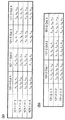
図2に、4×4光波長合分波器101−1および3×3光波長合分波器101−2において、λ1からλ12までの波長について、入出力ポート間を透過する信号の波長を示す。一般には「入力ポートXから入力され、出力ポートYから出力される信号の波長は、λ(X+Y-1)と、λ(X+Y-1)と基本周期単位で異なる波長(X、Yは1以上入出力ポート数以下の整数)である。」と定義できる。 In FIG. 2, in the 4 × 4 optical wavelength multiplexer / demultiplexer 101-1 and the 3 × 3 optical wavelength multiplexer / demultiplexer 101-2, the signals transmitted between the input and output ports for wavelengths from λ 1 to λ 12 are shown. Indicates the wavelength. In general, “wavelengths of signals that are input from the input port X and output from the output port Y are different wavelengths (X, Y + X−1) and λ (X + Y−1) in fundamental periods. Y is an integer greater than or equal to 1 and less than or equal to the number of input / output ports).
図2に示される入出力ポート間の透過特性を元に、4×4光波長合分波器101−1の第4入出力ポートと、3×3光波長合分波器101−2の第3出入力ポートが、送受2心の光ファイバ103で接続される場合に得られる、入出力ポート間の透過特性を図3に示す。ここで、4×4光波長合分波器101−1と、3×3光波長合分波器101−2は、(基本周期/Δλ)の値が互いに素(最大公約数が1)であるために、全ての入出力ポートの組み合わせで、λ1からλ12までの波長の内、少なくとも1波長の信号が透過する。
Based on the transmission characteristics between the input and output ports shown in FIG. 2, the fourth input / output port of the 4 × 4 optical wavelength multiplexer / demultiplexer 101-1 and the third input / output port of the 3 × 3 optical wavelength multiplexer / demultiplexer 101-2 are used. FIG. 3 shows the transmission characteristics between the input and output ports obtained when the three input / output ports are connected by the
各通信ノード102では、送信器104−1〜104−12、波長合波器105を用いて、λ1からλ12までの12波長が波長分割多重化された信号を出力するものとする。同様に、各通信ノード102では、波長合波器106、送信器107−1〜107−12を用いて、λ1からλ12までの12波長が波長分割多重化された信号を受信するものとする。この時、いずれかの通信ノード102から出力されたλ1からλ12までの12波長が波長分割多重化された信号は、4×4波長合分波器101−1あるいは3×3波長合分波器101−2の入力ポートに入力されると、図3に示される入出力特性に従って波長毎に定まる出力ポートに出力され、その出力ポートに接続されている通信ノード102において波長分波器106で分波され、信号波長に応じて定まる受光素子107−1から107−12のいずれかで受光される。ここで、図3に示される入出力特性により、どの入力ポートから信号を入力しても、全ての出力ポートから少なくとも1波長の信号が出力されることから、全通信ノード間でフルメッシュの接続性を得ることが出来る。即ち、2つの光波長合分波器をまたがって、1つのフルメッシュ接続網が得られる。
Each
この機能は、一般に、互いに素(最大公約数が1)なA、B2整数に対して、A×Δλの基本周期を有するN×N光波長合分波器とB×Δλの基本周期を有するM×M光波長合分波器を使用する場合に、A×B種類の波長を使用することで、必ず成立するものである。尚、NはA以下の値であれば、必ずしもAと同じ値である必要は無く、MもB以下の値であれば、必ずしもBと同じ値である必要は無く、全ての場合でフルメッシュの接続性を得られる。 This function generally has an N × N optical wavelength multiplexer / demultiplexer having a fundamental period of A × Δλ and a fundamental period of B × Δλ for A and B2 integers that are relatively prime (the greatest common divisor is 1). When the M × M optical wavelength multiplexer / demultiplexer is used, it is always established by using A × B types of wavelengths. Note that if N is a value less than or equal to A, it is not necessarily the same value as A, and if M is also a value less than or equal to B, it is not always necessary to be the same value as B, and in all cases full mesh Connectivity.
例えば、本実施形態では、A=4、B=3、N=4、M=3で、波長λ1からλ12を使用する場合を例に示したが、他にも、A=5、B=8、N=5、M=8で、波長λ1からλ40を使用する構成や、A=5、B=8、N=4、M=7で、波長λ1からλ40を使用する構成であっても同様の機能を実現することができる。 For example, in this embodiment, A = 4, B = 3, N = 4, and M = 3 and the wavelengths λ 1 to λ 12 are used as an example. However, A = 5, B = 8, N = 5, M = 8, wavelength λ 1 to λ 40 used, or A = 5, B = 8, N = 4, M = 7, wavelength λ 1 to λ 40 used Even if it is a structure, the same function is realizable.
(実施形態2)
図4に、本発明の実施形態1に係る光通信システムの構成を示し、図5、6に、その入出力ポート間の透過特性を示す。実施形態2は、A×Δλの基本周期を有するN×N光波長合分波器(NはA以下の整数)と、B×Δλの基本周期を有するM×M光波長合分波器(MはB以下の整数)を使用し、特にAとBの最大公約数が1でない場合であり、AとBの最小公倍数をCとするとき、波長λ1からλCが所定の間隔Δλで定義されている場合の光通信システムである。図4に、実施形態2としてA=6、B=4、N=6、M=4の場合を例にとって示す。即ち、波長λ1からλ12が所定の間隔Δλで定義されているものとする。
(Embodiment 2)
FIG. 4 shows the configuration of the optical communication system according to
以下に、本実施形態の原理を説明する。図4に示す光通信システムは、6×6光波長合分波器101−1、4×4光波長合分波器101−2、通信ノード102、送受2心の光ファイバ103、所定の波長の信号を送出する送信器104−1〜104−12、12×1波長合波器105、1×12波長分波器106、受光素子107−1〜107−12を含む。送信器104の数、波長合波器105の入力ポート数、波長分波器106の出力ポート数、受光素子107の数である12は、AとBの最小公倍数C、即ち定義した波長数に相当する。
The principle of this embodiment will be described below. The optical communication system shown in FIG. 4 includes a 6 × 6 optical wavelength multiplexer / demultiplexer 101-1, a 4 × 4 optical wavelength multiplexer / demultiplexer 101-2, a
6×6光波長合分波器101−1と4×4光波長合分波器101−2が設置され、6×6光波長合分波器101−1の第5入出力ポートと4×4光波長合分波器101−2の第4出入力ポートが送受2心の光ファイバ103で接続されるとともに、6×6光波長合分波器101−1の第6入出力ポートと4×4光波長合分波器101−2の第2出入力ポートが送受2心の光ファイバ103で接続される。6×6光波長合分波器101−1の第5・第6入出力ポートと、4×4光波長合分波器101−2の第2・第4入出力ポート以外の6×6光波長合分波器101−1および4×4光波長合分波器101−2の入出力ポートは、それぞれ通信ノード102と、送受2心の光ファイバ103で接続される。
The 6 × 6 optical wavelength multiplexer / demultiplexer 101-1 and the 4 × 4 optical wavelength multiplexer / demultiplexer 101-2 are installed, and the fifth input / output port of the 6 × 6 optical wavelength multiplexer / demultiplexer 101-1 and the 4 × The fourth input / output port of the 4-wavelength wavelength multiplexer / demultiplexer 101-2 is connected to the transmission / reception
通信ノード102の内部には、光信号の送信に関わる装置として、所定の波長の信号を送出する送信器104−1〜104−12と、この送信器104−1〜104−12の出力を入力とする波長合波器105を備える。波長合波器105の出力は、送受2心の光ファイバ103の内の1本を介して、6×6光波長合分波器101−1あるいは4×4光波長合分波器101−2の入力ポートに接続される。同じく、通信ノード102の内部には、光信号の受信に関わる装置として、入力されたWDM信号を波長に応じて定まるポートから出力する波長分波器106と、この波長分波器106の出力を入力とする受光素子107−1〜107−12を備える。波長分波器106の入力は送受2心の光ファイバ103の内の残りの1本を介して、6×6光波長合分波器101−1あるいは4×4光波長合分波器101−2の出力ポートに接続される。尚、ここでは各通信ノード102の入力と出力は、それぞれ光波長合分波器の同一番号の入出力ポートに接続されているが、必ずしも同一番号の入出力ポートに接続しなくともよい。
In the
6×6光波長合分波器101−1および4×4光波長合分波器101−2として、具体的にはアレイ導波路回折格子を使用する。アレイ導波路回折格子は、占有容積が小さく、多チャンネル化が容易である点で優れている。アレイ導波路回折格子は設計によって定まる基本周期(FSR)を有している。本実施形態においては、(基本周期/Δλ)の値の最大公約数が1でない2つの光波長合分波器を使用し、(基本周期/Δλ)の値の最大公約数と同数の送受2心の光ファイバ対を用いて光波長合分波器同士を接続する。具体的には、(基本周期/Δλ)の値の最大公約数が2である、基本周波数が6×Δλである6×6光波長合分波器101−1と、基本周期が4×Δλである4×4光波長合分波器101−2を使用し、2組の送受2心の光ファイバ103を用いて接続する場合を示す。
Specifically, array waveguide diffraction gratings are used as the 6 × 6 optical wavelength multiplexer / demultiplexer 101-1 and the 4 × 4 optical wavelength multiplexer / demultiplexer 101-2. The arrayed waveguide diffraction grating is excellent in that it occupies a small volume and can be easily multi-channeled. The arrayed waveguide grating has a fundamental period (FSR) determined by design. In the present embodiment, two optical wavelength multiplexers / demultiplexers whose (basic period / Δλ) value is not equal to 1 are used, and the same number of transmission /
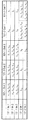
図5に、6×6光波長合分波器101−1および4×4光波長合分波器101−2において、λ1からλ12までの波長について、入出力ポート間を透過する信号の波長を示す。一般には「入力ポートXから入力され、出力ポートYから出力される信号の波長は、λ(X+Y-1)と、λ(X+Y-1)と基本周期単位で異なる波長(X、Yは1以上入出力ポート数以下の整数)である。」と定義できる。 FIG. 5 shows the signals transmitted through the input / output ports for wavelengths from λ 1 to λ 12 in the 6 × 6 optical wavelength multiplexer / demultiplexer 101-1 and the 4 × 4 optical wavelength multiplexer / demultiplexer 101-2. Indicates the wavelength. In general, “wavelengths of signals that are input from the input port X and output from the output port Y are different wavelengths (X, Y + X−1) and λ (X + Y−1) in fundamental periods. Y is an integer greater than or equal to 1 and less than or equal to the number of input / output ports).
図5に示す入出力ポート間の透過特性を元に、6×6光波長合分波器101−1の第5入出力ポートと4×4光波長合分波器101−2の第4出入力ポートが送受2心の光ファイバ103で接続されると同時に、6×6光波長合分波器101−1の第6入出力ポートと4×4光波長合分波器101−2の第2出入力ポートが送受2心の光ファイバ103で接続される場合に得られる、入出力ポート間の透過特性を図6に示す。ここで、6×6光波長合分波器101−1と、4×4光波長合分波器101−2は、(基本周期/Δλ)の値が互いに素(最大公約数が1)でなく、最大公約数が2である点に注意を要する。光波長合分波器の周期性により、光波長合分波器間を接続する送受2心の光ファイバ103が1組だけの場合、ある通信ノードから送出された信号は、この通信ノードが直接接続されていない光合分波器の出力ポートの内、1/2(一般には、1/((基本周期/Δλ)の最大公約数))のポートからしか出力されない。従って、光波長合分波器間を接続する送受2心の光ファイバ103を2組(一般には、(基本周期/Δλ)の最大公約数と同数組)に増やすことにより、全ての入出力ポートの組み合わせで、少なくとも1波長の信号が透過できるようにしている。
Based on the transmission characteristics between the input and output ports shown in FIG. 5, the fifth input / output port of the 6 × 6 optical wavelength multiplexer / demultiplexer 101-1 and the fourth output of the 4 × 4 optical wavelength multiplexer / demultiplexer 101-2 are shown. At the same time that the input ports are connected by the
各通信ノード102では、送信器104−1〜104−12、波長合波器105を用いて、λ1からλ12までの12波長が波長分割多重化された信号を出力するものとする。同様に、各通信ノード102では、波長合波器106、送信器107−1〜107−12を用いて、λ1からλ12までの12波長が波長分割多重化された信号を受信するものとする。
Each
この時、いずれかの通信ノード102から出力されたλ1からλ12までの12波長が波長分割多重化された信号は、6×6光波長合分波器101−1あるいは4×4光波長合分波器101−2の入力ポートに入力されると、図6に示す入出力特性に従って波長毎に定まる出力ポートに出力され、この出力ポートに接続されている通信ノード102において波長分波器106で分波され、信号波長に応じて定まる受光素子107−1から107−12のいずれかで受光される。ここで、図6に示す入出力特性により、どの入力ポートから信号を入力しても、全ての出力ポートから少なくとも1波長の信号が出力されることから、全通信ノード間でフルメッシュの接続性を得ることが出来る。即ち、2つの光波長合分波器をまたがって、1つのフルメッシュ接続網が得られる。
At this time, a signal in which 12 wavelengths from λ 1 to λ 12 output from any of the
この機能は、一般に、最大公約数が1でないA、B2整数に対して、A×Δλの基本周期を有するN×N光波長合分波器とB×Δλの基本周期を有するM×M光波長合分波器を使用する場合に、A、Bの最大公約数と同数組の送受2心の光ファイバを用いて適切なポート間を接続し、A、Bの最小公倍数と同数種類の波長を使用することで、必ず成立するものである。尚、NはA以下の値であれば、必ずしもAと同じ値である必要は無く、MもB以下の値であれば、必ずしもBと同じ値である必要はなく、全ての場合でフルメッシュの接続性を得られる。 In general, this function is obtained by using N × N optical wavelength multiplexer / demultiplexer having a fundamental period of A × Δλ and M × M light having a fundamental period of B × Δλ for A and B2 integers whose greatest common divisor is not 1. When using a wavelength multiplexer / demultiplexer, connect the appropriate ports using the same number of pairs of transmitting and receiving fibers as the greatest common divisor of A and B, and the same number of wavelengths as the least common multiple of A and B. By using, it is always true. Note that if N is a value less than or equal to A, it is not necessarily the same value as A, and if M is also a value less than or equal to B, it is not necessarily the same value as B. In all cases, full mesh Connectivity.
例えば、本実施形態では、A=4、B=6、N=4、M=6で、4×4アレイ導波路回折格子の第2入出力ポートと6×6アレイ導波路回折格子の第6出入力ポートとを接続するとともに、4×4アレイ導波路回折格子の第4入出力ポートと6×6アレイ導波路回折格子の第5出入力ポートとを接続し、波長λ1からλ12を使用する構成を示したが、他にも、A=6、B=9、N=6、M=9で、6×6アレイ導波路回折格子の第6入出力ポートと9×9アレイ導波路回折格子の第1出入力ポートとを接続すると共に、6×6アレイ導波路回折格子の第5入出力ポートと9×9アレイ導波路回折格子の第2出入力ポートとを接続し、6×6アレイ導波路回折格子の第4入出力ポートと9×9アレイ導波路回折格子の第3出入力ポートとを接続し、波長λ1からλ18を使用する構成や、A=6、B=8、N=6、M=8で、6×6アレイ導波路回折格子の第6入出力ポートと8×8アレイ導波路回折格子の第1出入力ポートとを接続するとともに、6×6アレイ導波路回折格子の第5入出力ポートと8×8アレイ導波路回折格子の第2出入力ポートとを接続し、6×6アレイ導波路回折格子の第4入出力ポートと8×8アレイ導波路回折格子の第3出入力ポートとを接続し、波長λ1からλ24を使用する構成であっても、同様の機能を実現できる。 For example, in this embodiment, A = 4, B = 6, N = 4, and M = 6, the second input / output port of the 4 × 4 array waveguide diffraction grating and the sixth of the 6 × 6 array waveguide diffraction grating. In addition to connecting the input / output port, the fourth input / output port of the 4 × 4 array waveguide diffraction grating and the fifth input / output port of the 6 × 6 array waveguide diffraction grating are connected, and wavelengths λ 1 to λ 12 are set. Although the configuration to be used is shown, in addition, when A = 6, B = 9, N = 6, M = 9, the sixth input / output port of the 6 × 6 array waveguide diffraction grating and the 9 × 9 array waveguide The first input / output port of the diffraction grating is connected, the fifth input / output port of the 6 × 6 array waveguide diffraction grating is connected to the second input / output port of the 9 × 9 array waveguide diffraction grating, and 6 × The fourth input / output port of the 6-array waveguide diffraction grating and the third input / output port of the 9 × 9 arrayed-waveguide diffraction grating are connected, and the wavelength λ A configuration using 1 to λ 18 , A = 6, B = 8, N = 6, M = 8, the sixth input / output port of the 6 × 6 array waveguide diffraction grating and the 8 × 8 array waveguide diffraction grating A 6 × 6 array, and a fifth input / output port of the 6 × 6 array waveguide diffraction grating and a second input / output port of the 8 × 8 array waveguide diffraction grating. the third output of the fourth output port and 8 × 8 AWG waveguide grating connected to the input port, be configured to use the lambda 24 wavelength lambda 1, implement the same function it can.
但し、本実施形態2の入出力ポート間の接続を変更し、4×4アレイ導波路回折格子の第4入出力ポートと6×6アレイ導波路回折格子の第6出入力ポートを接続するとともに、4×4アレイ導波路回折格子の第3入出力ポートと6×6アレイ導波路回折格子の第5出入力ポートを接続する場合には、フルメッシュの接続性を得ることが出来ない。本実施形態2で示す機能を得るためには、入出力ポート間の配線は、適切に選択する必要がある。 However, the connection between the input / output ports of the second embodiment is changed, and the fourth input / output port of the 4 × 4 array waveguide diffraction grating and the sixth input / output port of the 6 × 6 array waveguide diffraction grating are connected. When connecting the third input / output port of the 4 × 4 array waveguide diffraction grating and the fifth input / output port of the 6 × 6 array waveguide diffraction grating, full mesh connectivity cannot be obtained. In order to obtain the function shown in the second embodiment, it is necessary to appropriately select the wiring between the input / output ports.
(実施形態3)
図7に、本発明の実施形態3に係る光通信システムの構成を示し、図8、9に、その入出力ポート間の透過特性を示す。実施形態3は、K個の整数A1、A2、…、AKの内、どの2つの整数も互いに素(最大公約数が1)であり、K個の整数A1、A2、…、AKの積をDとするとき、波長λ1からλDが所定の間隔Δλで定義されていて、A1×ΔλからAK×Δλまでの基本周期を有するN1×N1光波長合分波器からNK×NK光波長合分波器までのK個の光波長合分波器(iを1以上K以下の整数とするとき、NiはAi以下の整数)を使用する光通信システムであるが、図7〜9に示す本実施形態では、K=3で、A1=N1=4、A2=N2=3、A3=N3=5、の場合を例にとって示す。即ち、波長λ1からλ60が所定の間隔Δλで定義されているものとする。
(Embodiment 3)
FIG. 7 shows the configuration of an optical communication system according to
以下に本実施形態の原理を説明する。
図7に示す光通信システムは、4×4光波長合分波器101−1、3×3光波長合分波器101−2、5×5光波長合分波器101−3、通信ノード102、送受2心の光ファイバ103、所定の波長の信号を送出する送信器104−1〜104−60、60×1波長合波器105、1×60波長分波器106、受光素子107−1〜107−60を含む。(送信器104の数、波長合波器105の入力ポート数、波長分波器106の出力ポート数、受光素子107の数である60は、A1×A2×A3、即ち定義した波長数に相当する。)
The principle of this embodiment will be described below.
The optical communication system shown in FIG. 7 includes a 4 × 4 optical wavelength multiplexer / demultiplexer 101-1, a 3 × 3 optical wavelength multiplexer / demultiplexer 101-2, a 5 × 5 optical wavelength multiplexer / demultiplexer 101-3, and a communication node. 102,
4×4光波長合分波器101−1と3×3光波長合分波器101−2と5×5光波長合分波器101−3が設置され、4×4光波長合分波器101−1の第4入出力ポートと3×3光波長合分波器101−2の第3出入力ポートが送受2心の光ファイバ103で接続され、4×4光波長合分波器101−1の第3入出力ポートと5×5光波長合分波器101−3の第5出入力ポートが送受2心の光ファイバ103で接続される。4×4光波長合分波器101−1の第3および第4入出力ポートと、3×3光波長合分波器101−2の第3入出力ポート、5×5光波長合分波器101−3の第5入出力ポート以外の各光波長合分波器の入出力ポートは、通信ノード102と、送受2心の光ファイバ103で接続される。
The 4 × 4 optical wavelength multiplexer / demultiplexer 101-1, the 3 × 3 optical wavelength multiplexer / demultiplexer 101-2, and the 5 × 5 optical wavelength multiplexer / demultiplexer 101-3 are installed, and the 4 × 4 optical wavelength multiplexer / demultiplexer is installed. A 4 × 4 optical wavelength multiplexer / demultiplexer is connected to the fourth input / output port of the optical unit 101-1 and the third input / output port of the 3 × 3 optical wavelength multiplexer / demultiplexer 101-2 through the
各通信ノード102の内部には、光信号の送信に関わる装置として、所定の波長の信号を送出する送信器104−1〜104−60と、この送信器104−1〜104−60の出力を入力とする波長合波器105を備える。この波長合波器105の出力は送受2心の光ファイバ103の内の1本を介して、4×4光波長合分波器101−1、3×3光波長合分波器101−2あるいは5×5光波長合分波器101−3の入力ポートに接続される。同じく、各通信ノード102の内部には、光信号の受信に関わる装置として、入力されたWDM信号を波長に応じて定まるポートから出力する波長分波器106と、この波長分波器106の出力を入力とする受光素子107−1〜107−60を備える。波長分波器106の入力は送受2心の光ファイバ103の内の残りの1本を介して、4×4光波長合分波器101−1、3×3光波長合分波器101−2あるいは5×5光波長合分波器101−3の出力ポートに接続される。尚、ここでは各通信ノード102の入力と出力は、それぞれ光波長合分波器の同一番号の入出力ポートに接続されているが、必ずしも同一番号の入出力ポートに接続しなくともよい。
In each
4×4光波長合分波器101−1、3×3光波長合分波器101−2および5×5光波長合分波器101−3として、具体的にはアレイ導波路回折格子を使用する。アレイ導波路回折格子は、占有容積が小さく、多チャンネル化が容易である点で優れている。アレイ導波路回折格子は設計によって定まる基本周期(FSR)を有している。本実施形態においては、いずれの2台を選択しても、(基本周期/Δλ)の値が互いに素(最大公約数が1)である3つの光波長合分波器を使用する。具体的には、基本周期が4×Δλである4×4光波長合分波器101−1、基本周期が3×Δλである3×3光波長合分波器101−2および基本周期が5×Δλである5×5光波長合分波器101−3を使用する場合を示す。図8に、この4×4光波長合分波器101−1、3×3光波長合分波器101−2および5×5光波長合分波器101−3において、入出力ポート間を透過する信号の波長を示す。一般には「入力ポートXから入力され、出力ポートYから出力される信号の波長は、λ(X+Y-1)と、λ(X+Y-1)と基本周期単位で異なる波長(X、Yは1以上入出力ポート数以下の整数)である。」と定義できる。 As the 4 × 4 optical wavelength multiplexer / demultiplexer 101-1, the 3 × 3 optical wavelength multiplexer / demultiplexer 101-2 and the 5 × 5 optical wavelength multiplexer / demultiplexer 101-3, specifically, an arrayed waveguide diffraction grating is used. use. The arrayed waveguide diffraction grating is excellent in that it occupies a small volume and can be easily multi-channeled. The arrayed waveguide grating has a fundamental period (FSR) determined by design. In the present embodiment, even if any two units are selected, three optical wavelength multiplexers / demultiplexers whose (basic period / Δλ) values are relatively prime (the greatest common divisor is 1) are used. Specifically, a 4 × 4 optical wavelength multiplexer / demultiplexer 101-1 having a fundamental period of 4 × Δλ, a 3 × 3 optical wavelength multiplexer / demultiplexer 101-2 having a fundamental period of 3 × Δλ, and a fundamental period of The case where the 5 × 5 optical wavelength multiplexer / demultiplexer 101-3 that is 5 × Δλ is used is shown. In FIG. 8, in the 4 × 4 optical wavelength multiplexer / demultiplexer 101-1, the 3 × 3 optical wavelength multiplexer / demultiplexer 101-2 and the 5 × 5 optical wavelength multiplexer / demultiplexer 101-3, the input / output ports are connected. Indicates the wavelength of the transmitted signal. In general, “wavelengths of signals that are input from the input port X and output from the output port Y are different wavelengths (X, Y + X−1) and λ (X + Y−1) in fundamental periods. Y is an integer greater than or equal to 1 and less than or equal to the number of input / output ports).
図8に示す入出力ポート間の透過特性を元に、4×4光波長合分波器101−1の第4入出力ポートと、3×3光波長合分波器101−2の第3出入力ポートが送受2心の光ファイバ103で接続され、4×4光波長合分波器101−1の第3入出力ポートと、5×5光波長合分波器101−3の第5出入力ポートが送受2心の光ファイバ103で接続される場合に得られる、入出力ポート間の透過特性を図9に示す。ここで、4×4光波長合分波器101−1と、3×3光波長合分波器101−2、5×5光波長合分波器101−3は、いずれの2台を選択しても(基本周期/Δλ)の値が互いに素(最大公約数が1)であるために、全ての入出力ポートの組み合わせで、λ1からλ60までの波長のうち、少なくとも1波長の信号が透過する。
Based on the transmission characteristics between the input and output ports shown in FIG. 8, the fourth input / output port of the 4 × 4 optical wavelength multiplexer / demultiplexer 101-1 and the third of the 3 × 3 optical wavelength multiplexer / demultiplexer 101-2 are used. The input / output port is connected by two
各通信ノード102では、送信器104−1〜104−60、波長合波器105を用いて、λ1からλ60波長が波長分割多重化された信号を出力するものとする。同様に各通信ノード102では、波長合波器106、送信器107−1〜107−60を用いて、λ1からλ60までの60波長が波長分割多重化された信号を受信するものとする。
Each
このとき、いずれかの通信ノード102から出力されたλ1からλ60までの60波長が波長分割多重化された信号は、4×4光波長合分波器101−1か3×3光波長合分波器101−2、あるいは5×5光波長合分波器101−3の入力ポートに入力されると、図9に示す入出力特性従って波長毎に定まる出力ポートに出力され、その出力ポートに接続されている通信ノード102において波長分波器106で分波され、信号波長に応じて定まる受光素子107−1〜107−60のいずれかで受光される。ここで、図9に示す入出力特性により、どの入力ポートから信号を入力しても、全ての出力ポートから少なくとも1波長の信号が出力されることから、全通信ノード間でフルメッシュの接続性を得ることができる。即ち、3つの光波長合分波器をまたがって、1つのフルメッシュ接続網が得られる。
At this time, a signal obtained by wavelength-
この機能は、一般に、どの2つの整数も互いに素(最大公約数が1)であるK個の整数A1、A2、…、AKに対して、A1×ΔλからAK×Δλまでの基本周期を有するN1×N1光波長合分波器からNK×NK光波長合分波器までのK個の光波長合分波器(iを1以上K以下の整数とするとき、NiはAi以下の整数)を使用する場合に、K個の整数A1、A2、…、AKの積に相当する数の種類の波長を使用することで、必ず成立するものである。尚、NiはAi以下の値であれば、必ずAiと同じ値である必要は無く、全ての場合でフルメッシュの接続性を得られる。 This function is generally derived from A 1 × Δλ to A K × Δλ for K integers A 1 , A 2 ,..., A K , where any two integers are relatively prime (the greatest common divisor is 1). N optical wavelength multiplexers / demultiplexers from N 1 × N 1 optical wavelength multiplexer / demultiplexer having the basic period of N K × N K optical wavelength multiplexer / demultiplexer (i is an integer between 1 and K) When N i is an integer equal to or less than A i , it is always established by using a number of types of wavelengths corresponding to the product of K integers A 1 , A 2 ,. Is. Incidentally, N i is if the following values A i, need not be obtained connectivity full mesh in all cases is always the same value as A i.
例えば、本実施形態では、K=3で、A1=N1=4、A2=N2=3、A3=N3=5、であり、波長λ1からλ60を使用し、第1と第2の光波長合分波器間と第1と第3の光波長合分波器間を送受2心の光ファイバで接続する場合を例に示したが、他にも、K=4で、A1=N1=3、A2=N2=4、A3=N3=5、A4=N4=7であり、波長λ1からλ420を使用し、第1と第2の光波長合分波器間と第2と第3の光波長合分波器と第2と第4の光波長合分波器間を送受2心の光ファイバで接続する構成であっても、同様の機能を実現できる。 For example, in this embodiment, K = 3, A 1 = N 1 = 4, A 2 = N 2 = 3, A 3 = N 3 = 5, and wavelengths λ 1 to λ 60 are used. The case where the optical fiber between the first and second optical wavelength multiplexers / demultiplexers and the first and third optical wavelength multiplexers / demultiplexers are connected by an optical fiber having two transmission / reception cores is shown as an example. 4, A 1 = N 1 = 3, A 2 = N 2 = 4, A 3 = N 3 = 5, A 4 = N 4 = 7, and using wavelengths λ 1 to λ 420 , The second optical wavelength multiplexer / demultiplexer, the second and third optical wavelength multiplexers / demultiplexers, and the second and fourth optical wavelength multiplexers / demultiplexers are connected by an optical fiber having two cores. However, the same function can be realized.
尚、本実施形態では、A1、A2、A3のどの2数も互いに素である場合に注目して説明したが、最大公約数が1でない2数が存在する場合でも、最大公約数が1でない光波長合分波器間の送受2心の光ファイバ数を、光波長合分波器の(基本周期/Δλ)の最大公約数と同数組にすれば、実施形態2での説明と同じ理由で、フルメッシュの接続特性を得られる。 In the present embodiment, the description has been given focusing on the case where any two of A 1 , A 2 , and A 3 are relatively prime. However, even when there are two numbers whose greatest common divisor is not 1, the greatest common divisor is present. In the second embodiment, the number of optical fibers in two optical fibers between the optical wavelength multiplexers / demultiplexers where N is not 1 is set to the same number as the greatest common divisor of (basic period / Δλ) of the optical wavelength multiplexer / demultiplexer. For the same reason, a full mesh connection characteristic can be obtained.
例えば、K=3で、A1=N1=4、A2=N2=5、A3=N3=6であり、波長λ1からλ120を使用し、第1と第2の光波長合分波器間と第1と第3の光波長合分波器間を送受2心の光ファイバで接続する場合、第1と第3の光波長合分波器を接続する送受2心の光ファイバの数を2組とすれば、同様の機能を実現できる。 For example, when K = 3, A 1 = N 1 = 4, A 2 = N 2 = 5, A 3 = N 3 = 6, using wavelengths λ 1 to λ 120 , the first and second lights When connecting between the wavelength multiplexer / demultiplexer and between the first and third optical wavelength multiplexer / demultiplexers with a two-fiber optical fiber, two transmitter / receiver cores connecting the first and third optical wavelength multiplexer / demultiplexers. If the number of optical fibers is two, the same function can be realized.
但し、第1と第3の光波長合分波器間の接続については、実施形態2での説明と同じ理由で、配線を適切に選択する必要がある。例えば、4×4アレイ導波路回折格子の第2入出力ポートと6×6アレイ導波路回折格子の第6出入力ポートを接続するとともに、4×4アレイ導波路回折格子の第4入出力ポートと6×6アレイ導波路回折格子の第5出入力ポートを接続する場合には、フルメッシュの接続性を得られる。しかし、4×4アレイ導波路回折格子の第4入出力ポートと6×6アレイ導波路回折格子の第6出入力ポートを接続するとともに、4×4アレイ導波路回折格子の第3入出力ポートと6×6アレイ導波路回折格子の第5出入力ポートを接続する場合には、フルメッシュの接続性を得ることができない。 However, for the connection between the first and third optical wavelength multiplexers / demultiplexers, it is necessary to appropriately select the wiring for the same reason as described in the second embodiment. For example, the second input / output port of the 4 × 4 array waveguide diffraction grating is connected to the sixth input / output port of the 6 × 6 array waveguide diffraction grating, and the fourth input / output port of the 4 × 4 array waveguide diffraction grating is connected. When connecting the fifth input / output port of the 6 × 6 arrayed waveguide diffraction grating, full mesh connectivity can be obtained. However, the fourth input / output port of the 4 × 4 array waveguide diffraction grating and the sixth input / output port of the 6 × 6 array waveguide diffraction grating are connected, and the third input / output port of the 4 × 4 array waveguide diffraction grating is connected. When connecting the 5th input / output port of the 6 × 6 arrayed waveguide diffraction grating, full mesh connectivity cannot be obtained.
(実施形態4)
実施形態4は、実施形態3において、定義する波長の数を変更し、どの2つの整数も互いに素(最大公約数が1)であるK個の整数A1、A2、…、AKの内、2つの整数の積の最大値をCとするとき、波長λ1からλCを定義するものである。実施形態3と同様に、K=3で、A1=N1=4、A2=N2=3、A3=N3=5の場合には、波長λ1からλ20が所定の間隔Δλで定義される。このとき、送信器の数、波長合波器の入力ポート数、波長分波器の出力ポート数、受光素子の数が60から20に変わる他は、実施形態3と構成は同じである。また、4×4光波長合分波器101−1、3×3光波長合分波器101−2、5×5光波長合分波器101−3の入出力ポート間の透過特性は、波長λ1からλ20のみが意味を有する他は、図9と変わらない。
(Embodiment 4)
In the fourth embodiment, the number of wavelengths defined in the third embodiment is changed, and any two integers of K integers A 1 , A 2 ,..., A K are relatively prime (the greatest common divisor is 1). Among them, when the maximum value of the product of two integers is C, wavelengths λ 1 to λ C are defined. As in the third embodiment, when K = 3, A 1 = N 1 = 4, A 2 = N 2 = 3, and A 3 = N 3 = 5, the wavelengths λ 1 to λ 20 have a predetermined interval. It is defined by Δλ. At this time, the configuration is the same as that of the third embodiment except that the number of transmitters, the number of input ports of the wavelength multiplexer, the number of output ports of the wavelength demultiplexer, and the number of light receiving elements are changed from 60 to 20. Further, the transmission characteristics between the input and output ports of the 4 × 4 optical wavelength multiplexer / demultiplexer 101-1, the 3 × 3 optical wavelength multiplexer / demultiplexer 101-2, and the 5 × 5 optical wavelength multiplexer / demultiplexer 101-3 are: 9 is the same as FIG. 9 except that only the wavelengths λ 1 to λ 20 are significant.
このとき、いずれかの通信ノード102から出力されたλ1からλ20までの20波長が波長分割多重化された信号は、4×4光波長合分波器101−1か3×3光波長合分波器101−2、あるいは5×5光波長合分波器101−3の入力ポートに入力されると、図9に示す入出力特性の内、波長λ1からλ20に関する特性に従って、波長毎に定まる出力ポートに出力され、その出力ポートに接続されている通信ノード102において波長分波器106で分波され、信号波長に応じて定まる受光素子107−1〜107−20のいずれかで受光される。ここで、図9に示す入出力特性により、同じ光波長合分波器の入出力ポート間と、送受2心の光ファイバで接続されている光波長合分波器の入出力ポート間については、全ての入出力ポートの組み合わせで、λ1からλ20までの波長の内、少なくとも1波長の信号が透過する。但し、送受2心の光ファイバで直接接続されていない光波長合分波器の入出力ポート間については、必ずしも透過する信号が存在しない。即ち、少なくとも送受2心の光ファイバで直接接続されている光波長合分波器に関しては、光波長合分波器をまたがってフルメッシュの接続性を得ることが出来る。
At this time, a signal obtained by wavelength-
この機能は、一般に、どの2つの整数も互いに素(最大公約数が1)であるK個の整数A1、A2、…、AKに対して、A1×ΔλからAK×Δλまでの基本周期を有するN1×N1光波長合分波器からNK×NK光波長合分波器までのK個の光波長合分波器(iを1以上K以下の整数とするとき、NiはAi以下の整数)を使用する場合、K個の整数A1、A2、…、AKの内、2つの整数の積の最大値に相当する数の種類の波長を使用することで、必ず成立するものである。尚、NiはAi以下の値であれば必ずしもAiと同じ値である必要は無く、Ni≦Aiの全ての場合において、送受2心の光ファイバで直接接続されている光波長合分波器に関してフルメッシュの接続性を得られる。 This function is generally derived from A 1 × Δλ to A K × Δλ for K integers A 1 , A 2 ,..., A K , where any two integers are relatively prime (the greatest common divisor is 1). N optical wavelength multiplexers / demultiplexers from N 1 × N 1 optical wavelength multiplexer / demultiplexer having the basic period of N K × N K optical wavelength multiplexer / demultiplexer (i is an integer between 1 and K) When N i is an integer equal to or less than A i , among K integers A 1 , A 2 ,..., A K , the number of types of wavelengths corresponding to the maximum value of the product of two integers is selected. By using it, it is always established. Incidentally, N i is not necessarily the same value as always A i if the following values A i, in the case of all N i ≦ A i, the optical wavelength that is directly connected with transmission and reception 2-core optical fiber Full-mesh connectivity can be obtained for the multiplexer / demultiplexer.
例えば、本実施形態では、K=3で、A1=N1=4、A2=N2=3、A3=N3=5であり、波長λ1からλ20を使用し、第1と第2の光波長合分波器間と第1と第3の光波長合分波器間を送受2心の光ファイバで接続する場合を例に示したが、他にも、K=4で、A1=N1=3、A2=N2=4、A3=N3=5、A4=N4=7であり、波長λ1からλ35を使用し、第1と第2の光波長合分波器間と第2と第3の光波長合分波器と第3と第4の光波長合分波器間を送受2心の光ファイバで接続する構成であっても、同様の機能を実現できる。 For example, in this embodiment, K = 3, A 1 = N 1 = 4, A 2 = N 2 = 3, A 3 = N 3 = 5, the wavelengths λ 1 to λ 20 are used, and the first As an example, a case where the optical fiber between the first and third optical wavelength multiplexers / demultiplexers and the first and third optical wavelength multiplexers / demultiplexers are connected by an optical fiber having two transmission / reception cores is shown. A 1 = N 1 = 3, A 2 = N 2 = 4, A 3 = N 3 = 5, A 4 = N 4 = 7, using wavelengths λ 1 to λ 35 , The two optical wavelength multiplexers / demultiplexers, the second and third optical wavelength multiplexers / demultiplexers, and the third and fourth optical wavelength multiplexers / demultiplexers are connected by a two-core optical fiber. The same function can be realized.
尚、K個の整数A1、A2、…、AKの中に最大公約数が1でない2数が存在する場合でも、最大公約数が1でない光波長合分波器間の送受2心の光ファイバ数を、光波長合分波器の(基本周期/Δλ)の最大公約数と同数組にすれば、実施形態2での説明と同じ理由で、同様の接続性を得られる。 It should be noted that even if there are two integers whose maximum common divisor is not 1 among the K integers A 1 , A 2 ,... If the number of optical fibers is set to the same number as the greatest common divisor of (basic period / Δλ) of the optical wavelength multiplexer / demultiplexer, the same connectivity can be obtained for the same reason as described in the second embodiment.
例えば、K=3で、A1=N1=4、A2=N2=5、A3=N3=6であり、波長λ1からλ30を使用し、第2と第3の光波長合分波器間と第1と第3の光波長合分波器間を送受2心の光ファイバで接続する場合、第1と第3の光波長合分波器間を接続する送受2心の光ファイバの数を2組とすれば、同様の機能を実現できる。
For example, if K = 3, A 1 = N 1 = 4, A 2 = N 2 = 5, A 3 = N 3 = 6, using wavelengths λ 1 to λ 30 , the second and third lights When connecting between the wavelength multiplexer / demultiplexers and between the first and third optical wavelength multiplexer / demultiplexers with two optical fibers, the transmitter /
但し、第1と第3の光波長合分波器間の接続については、実施形態2での説明と同じ理由で、配線を適切に選択する必要がある。例えば、4×4アレイ導波路回折格子の第2入出力ポートと6×6アレイ導波路回折格子の第6出入力ポートを接続するとともに、4×4アレイ導波路回折格子の第4入出力ポートと6×6アレイ導波路回折格子の第5出入力ポートを接続する場合には、フルメッシュの接続性を得られる。しかし、4×4アレイ導波路回折格子の第4入出力ポートと6×6アレイ導波路回折格子の第6出入力ポートを接続するとともに、4×4アレイ導波路回折格子の第3入出力ポートと6×6アレイ導波路回折格子の第5出入力ポートを接続する場合には、フルメッシュの接続性を得ることができない。 However, for the connection between the first and third optical wavelength multiplexers / demultiplexers, it is necessary to appropriately select the wiring for the same reason as described in the second embodiment. For example, the second input / output port of the 4 × 4 array waveguide diffraction grating is connected to the sixth input / output port of the 6 × 6 array waveguide diffraction grating, and the fourth input / output port of the 4 × 4 array waveguide diffraction grating is connected. When connecting the fifth input / output port of the 6 × 6 arrayed waveguide diffraction grating, full mesh connectivity can be obtained. However, the fourth input / output port of the 4 × 4 array waveguide diffraction grating and the sixth input / output port of the 6 × 6 array waveguide diffraction grating are connected, and the third input / output port of the 4 × 4 array waveguide diffraction grating is connected. When connecting the 5th input / output port of the 6 × 6 arrayed waveguide diffraction grating, full mesh connectivity cannot be obtained.
また、K個の整数A1、A2、…、AKの中に同じ整数が含まれていても、光波長合分波器間が送受2心の光ファイバで接続されていなければ、同様の接続性を得られる。 In addition, even if the same integer is included in K integers A 1 , A 2 ,..., A K , the same applies unless the optical wavelength multiplexers / demultiplexers are connected by two optical fibers. Connectivity.
例えば、K=3で、A1=N1=4、A2=N2=5、A3=N3=4であり、波長λ1からλ20を使用し、第1と第2の光波長合分波器間と第2と第3の光波長合分波器間を送受2心の光ファイバで接続する場合にも、同様の機能を実現できる。 For example, when K = 3, A 1 = N 1 = 4, A 2 = N 2 = 5, A 3 = N 3 = 4, using wavelengths λ 1 to λ 20 , the first and second lights A similar function can also be realized when the wavelength multiplexer / demultiplexer and the second and third optical wavelength multiplexer / demultiplexers are connected by an optical fiber having two transmission / reception cores.
(実施形態5)
図10に、本発明の実施形態5に係る光通信システムの構成を示し、図11に、その入出力ポート間の透過特性を示す。実施形態5は、K個の整数A1、A2、…、AKの内、どの2つの整数も互いに素(最大公約数が1)であり、K個の整数A1、A2、…、AKの積をDとするとき、波長λ1からλDが所定の間隔Δλで定義されていて、A1×ΔλからAK×Δλまでの基本周期を有するN1×N1光波長合分波器からNK×NK光波長合分波器までのK個の光波長合分波器(iを1以上K以下の整数とするとき、NiはAi以下の整数)を使用する光通信システムであるが、図10、11に示す本実施形態では、K=3で、A1=N1=4、A2=N2=3、A3=N3=5、の場合を例にとって示す。即ち、波長λ1からλ60が所定の間隔Δλで定義されているものとする。
(Embodiment 5)
FIG. 10 shows the configuration of an optical communication system according to
以下に、本実施形態の原理を説明する。
図10に示す光通信システムは、4×4光波長合分波器101−1、3×3光波長合分波器101−2、5×5光波長合分波器101−3、通信ノード102、送受2心の光ファイバ103、所定の波長の信号を送出する送信器104−1〜104−60、60×1波長合波器105、1×60波長分波器106、受光素子107−1〜107−60を含む。(送信器104の数、波長合波器105の入力ポート数、波長分波器106の出力ポート数、受光素子107の数60は、A1×A2×A3、即ち定義した波長数に相当する。)
The principle of this embodiment will be described below.
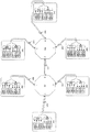
The optical communication system shown in FIG. 10 includes a 4 × 4 optical wavelength multiplexer / demultiplexer 101-1, a 3 × 3 optical wavelength multiplexer / demultiplexer 101-2, a 5 × 5 optical wavelength multiplexer / demultiplexer 101-3, and a communication node. 102,
4×4光波長合分波器101−1と3×3光波長合分波器101−2と5×5光波長合分波器101−3が設置され、4×4光波長合分波器101−1の第4入出力ポートと3×3光波長合分波器101−2の第3出入力ポートが送受2心の光ファイバ103で接続され、4×4光波長合分波器101−1の第3入出力ポートと5×5光波長合分波器101−3の第5出入力ポートが送受2心の光ファイバ103で接続され、3×3光波長合分波器101−2の第2入出力ポートと5×5光波長合分波器101−3の第4出入力ポートが送受2心の光ファイバ103で接続される。4×4光波長合分波器101−1の第3および第4入出力ポートと、3×3光波長合分波器101−2の第3および第2入出力ポート、5×5光波長合分波器101−3の第5および第4入出力ポート以外の入出力ポートは、通信ノード102と、送受2心の光ファイバ103で接続される。全ての光波長合分波器の組み合わせが、送受2心の光ファイバ103で直接接続されていることが実施形態5の特徴である。
The 4 × 4 optical wavelength multiplexer / demultiplexer 101-1, the 3 × 3 optical wavelength multiplexer / demultiplexer 101-2, and the 5 × 5 optical wavelength multiplexer / demultiplexer 101-3 are installed, and the 4 × 4 optical wavelength multiplexer / demultiplexer is installed. A 4 × 4 optical wavelength multiplexer / demultiplexer is connected to the fourth input / output port of the optical unit 101-1 and the third input / output port of the 3 × 3 optical wavelength multiplexer / demultiplexer 101-2 through the
通信ノード102の内部には、光信号の送信に関わる装置として、所定の波長の信号を送出する送信器104−1〜104−60と、この送信器104−1〜104−60の出力を入力とする波長合波器105を備える。この波長合波器105の出力は送受2心の光ファイバ103の内の1本を介して、4×4光波長合分波器101−1、3×3光波長合分波器101−2あるいは5×5光波長合分波器101−3の入力ポートに接続される。同じく、通信ノード102の内部には、光信号の受信に関わる装置として、入力されたWDM信号を波長に応じて定まるポートから出力する波長分波器106と、この波長分波器106の出力を入力とする受光素子107−1〜107−60を備える。波長分波器106の入力は送受2心の光ファイバ103の内の残りの1本を介して、4×4光波長合分波器101−1、3×3光波長合分波器101−2あるいは5×5光波長合分波器101−3の出力ポートに接続される。尚、ここでは各通信ノード102の入力と出力は、それぞれ光波長合分波器の同一番号の入出力ポートに接続されているが、必ずしも同一番号の入出力ポートに接続しなくともよい。
In the
4×4光波長合分波器101−1、3×3光波長合分波器101−2および5×5光波長合分波器101−3として、具体的にはアレイ導波路回折格子を使用する。アレイ導波路回折格子は、占有容積が小さく、多チャンネル化が容易である点で優れる。アレイ導波路回折格子は設計によって定まる基本周期(FSR)を有している。本実施形態においては、いずれの2台を選択しても、(基本周期/Δλ)の値が互いに素(最大公約数が1)である3つの光波長合分波器を使用する。具体的には、基本周期が4×Δλである4×4光波長合分波器101−1、基本周期が3×Δλである3×3光波長合分波器101−2および基本周期が5×Δλである5×5光波長合分波器101−3を使用する場合を示す。4×4光波長合分波器101−1、3×3光波長合分波器101−2および5×5光波長合分波器101−3において、入出力ポート間を透過する信号の波長は、図8に示したものと同じである。一般には「入力ポートXから入力され、出力ポートYから出力される信号の波長は、λ(X+Y-1)と、λ(X+Y-1)と基本周期単位で異なる波長(X、Yは1以上入出力ポート数以下の整数)である。」と定義できる。 As the 4 × 4 optical wavelength multiplexer / demultiplexer 101-1, the 3 × 3 optical wavelength multiplexer / demultiplexer 101-2 and the 5 × 5 optical wavelength multiplexer / demultiplexer 101-3, specifically, an arrayed waveguide diffraction grating is used. use. The arrayed waveguide diffraction grating is excellent in that it occupies a small volume and can be easily multi-channeled. The arrayed waveguide grating has a fundamental period (FSR) determined by design. In the present embodiment, even if any two units are selected, three optical wavelength multiplexers / demultiplexers whose (basic period / Δλ) values are relatively prime (the greatest common divisor is 1) are used. Specifically, a 4 × 4 optical wavelength multiplexer / demultiplexer 101-1 having a fundamental period of 4 × Δλ, a 3 × 3 optical wavelength multiplexer / demultiplexer 101-2 having a fundamental period of 3 × Δλ, and a fundamental period of The case where the 5 × 5 optical wavelength multiplexer / demultiplexer 101-3 that is 5 × Δλ is used is shown. 4 × 4 optical wavelength multiplexer / demultiplexer 101-1, 3 × 3 optical wavelength multiplexer / demultiplexer 101-2 and 5 × 5 optical wavelength multiplexer / demultiplexer 101-3, the wavelength of a signal transmitted between input and output ports Is the same as that shown in FIG. In general, “wavelengths of signals that are input from the input port X and output from the output port Y are different wavelengths (X, Y + X−1) and λ (X + Y−1) in fundamental periods. Y is an integer greater than or equal to 1 and less than or equal to the number of input / output ports).
図8に示す入出力ポート間の透過特性を元に、4×4光波長合分波器101−1の第4入出力ポートと3×3光波長合分波器101−2の第3出入力ポートが送受2心の光ファイバ103で接続され、4×4光波長合分波器101−1の第3入出力ポートと5×5光波長合分波器101−3の第5出入力ポートが送受2心の光ファイバ103で接続され、3×3光波長合分波器101−2の第2入出力ポートと5×5光波長合分波器101−3の第4出入力ポートが送受2心の光ファイバ103で接続される場合に得られる、入出力ポート間の透過特性を図11に示す。
Based on the transmission characteristics between the input / output ports shown in FIG. 8, the fourth input / output port of the 4 × 4 optical wavelength multiplexer / demultiplexer 101-1 and the third output of the 3 × 3 optical wavelength multiplexer / demultiplexer 101-2 are shown. The input port is connected by the
ここで、4×4光波長合分波器101−1と、3×3光波長合分波器101−2、5×5光波長合分波器101−3は、いずれの2台を選択しても(基本周期/Δλ)の値が互いに素(最大公約数が1)であるために、全ての入出力ポートの組み合わせで、λ1からλ60までの波長のうち、少なくとも1波長の信号が透過する。 Here, either 4 × 4 optical wavelength multiplexer / demultiplexer 101-1 or 3 × 3 optical wavelength multiplexer / demultiplexer 101-2, or 5 × 5 optical wavelength multiplexer / demultiplexer 101-3 is selected. Even so, since the value of (fundamental period / Δλ) is relatively prime (the greatest common divisor is 1), at least one of the wavelengths from λ 1 to λ 60 among the combinations of all input / output ports. The signal is transmitted.
各通信ノード102では、送信器104−1〜104−60、波長合波器105を用いて、λ1からλ60波長が波長分割多重化された信号を出力するものとする。同様に各通信ノード102では、波長合波器106、送信器107−1〜107−60を用いて、λ1からλ60までの60波長が波長分割多重化された信号を受信するものとする。
Each
このとき、いずれかの通信ノード102から出力されたλ1からλ60までの60波長が波長分割多重化された信号は、4×4光波長合分波器101−1か3×3光波長合分波器101−2、あるいは5×5光波長合分波器101−3の入力ポートに入力されると、図8に示す入出力特性従って波長毎に定まる出力ポートに出力され、その出力ポートに接続されている通信ノード102において波長分波器106で分波され、信号波長に応じて定まる受光素子107−1〜107−60のいずれかで受光される。ここで、図11に示す入出力特性により、どの入力ポートから信号を入力しても、全ての出力ポートから少なくとも1波長の信号が出力されることから、全通信ノード間でフルメッシュの接続性を得ることができる。即ち、3つの光波長合分波器をまたがって、1つのフルメッシュ接続網が得られる。
At this time, a signal obtained by wavelength-
また、仮に光波長合分波器間を直接接続する送受2心の光ファイバ103の内のいずれかが断線したとしても、すでに示した実施形態3の場合と同様に、フルメッシュの接続性は維持される。
Further, even if any one of the
この機能は、一般に、どの2つの整数も互いに素(最大公約数が1)であるK個の整数A1、A2、…、AKに対して、A1×ΔλからAK×Δλまでの基本周期を有するN1×N1光波長合分波器からNK×NK光波長合分波器までのK個の光波長合分波器(iを1以上K以下の整数とするとき、NiはAi以下の整数)を使用し、全ての光波長合分波器の組み合わせが、直通の光ファイバで接続されている場合に、K個の整数A1、A2、…、AKの積に相当する数の種類の波長を使用することで、必ず成立するものである。尚、NiはAi以下の値であれば、必ずしもAiと同じ値である必要は無く、Ni≦Aiの全ての場合でフルメッシュの接続性を得られる。 This function is generally derived from A 1 × Δλ to A K × Δλ for K integers A 1 , A 2 ,..., A K , where any two integers are relatively prime (the greatest common divisor is 1). N optical wavelength multiplexers / demultiplexers from N 1 × N 1 optical wavelength multiplexer / demultiplexer having the basic period of N K × N K optical wavelength multiplexer / demultiplexer (i is an integer between 1 and K) N i is an integer equal to or less than A i ), and when all combinations of optical wavelength multiplexers / demultiplexers are connected by direct optical fibers, K integers A 1 , A 2 ,. , by using a wavelength of the number of types corresponding to the product of a K, it is to always satisfied. Note that if Ni is a value equal to or less than A i , it is not necessarily the same value as A i, and full mesh connectivity can be obtained in all cases where N i ≦ A i .
例えば、本実施形態では、K=3で、A1=N1=4、A2=N2=3、A3=N3=5、であり、波長λ1からλ60を使用し、全ての組み合わせの光波長合分波器間を送受2心の光ファイバで接続する場合を例に示したが、他にも、K=4で、A1=N1=4、A2=N2=5、A3=N3=7、A4=N4=9であり、波長λ1からλ1260を使用し、全ての組み合わせの光波長合分波器間を送受2心の光ファイバで接続する構成であっても、同様の機能を実現できる。 For example, in this embodiment, K = 3, A 1 = N 1 = 4, A 2 = N 2 = 3, A 3 = N 3 = 5, and the wavelengths λ 1 to λ 60 are used. In the above example, the optical wavelength multiplexers / demultiplexers of the above-mentioned combinations are connected by two optical fibers of transmission and reception. However, in addition, K = 4, A 1 = N 1 = 4, A 2 = N 2 = 5, A 3 = N 3 = 7, A 4 = N 4 = 9, using wavelengths λ 1 to λ 1260 , and transmitting and receiving two optical fibers between optical wavelength multiplexers / demultiplexers Similar functions can be realized even with a connection configuration.
尚、本実施形態では、A1、A2、A3のどの2数も互いに素である場合に注目して説明したが、最大公約数が1でない2数が存在する場合でも、最大公約数が1でない光波長合分波器間の送受2心の光ファイバ数を、光波長合分波器の(基本周期/Δλ)の最大公約数と同数組にすれば、実施形態2での説明と同じ理由で、フルメッシュの接続特性を得られる。例えば、K=3で、A1=N1=4、A2=N2=5、A3=N3=6であり、波長λ1からλ120を使用し、全ての組み合わせの光波長合分波器間を送受2心の光ファイバで接続する場合、第1と第3の光波長合分波器間を接続する送受2心の光ファイバの数を2組とすれば、同様の機能を実現できる。 In the present embodiment, the description has been given focusing on the case where any two of A 1 , A 2 , and A 3 are relatively prime. However, even when there are two numbers whose greatest common divisor is not 1, the greatest common divisor is present. In the second embodiment, the number of optical fibers in two optical fibers between the optical wavelength multiplexers / demultiplexers where N is not 1 is set to the same number as the greatest common divisor of (basic period / Δλ) of the optical wavelength multiplexer / demultiplexer. For the same reason, a full mesh connection characteristic can be obtained. For example, when K = 3, A 1 = N 1 = 4, A 2 = N 2 = 5, A 3 = N 3 = 6, wavelengths λ 1 to λ 120 are used, and all combinations of optical wavelength combinations are used. When the duplexers are connected by two optical fibers for transmission and reception, the same function can be achieved if the number of optical fibers for transmission and reception two fibers connecting the first and third optical wavelength multiplexers / demultiplexers is two. Can be realized.
但し、第1と第3の光波長合分波器間の接続については、実施形態2での説明と同じ理由で、配線を適切に選択する必要がある。例えば、4×4アレイ導波路回折格子の第2入出力ポートと6×6アレイ導波路回折格子の第6出入力ポートを接続するとともに、4×4アレイ導波路回折格子の第4入出力ポートと6×6アレイ導波路回折格子の第5出入力ポートを接続する場合には、フルメッシュの接続性を得られる。しかし、4×4アレイ導波路回折格子の第4入出力ポートと6×6アレイ導波路回折格子の第6出入力ポートを接続するとともに、4×4アレイ導波路回折格子の第3入出力ポートと6×6アレイ導波路回折格子の第5出入力ポートを接続する場合には、フルメッシュの接続性を得ることができない。 However, for the connection between the first and third optical wavelength multiplexers / demultiplexers, it is necessary to appropriately select the wiring for the same reason as described in the second embodiment. For example, the second input / output port of the 4 × 4 array waveguide diffraction grating is connected to the sixth input / output port of the 6 × 6 array waveguide diffraction grating, and the fourth input / output port of the 4 × 4 array waveguide diffraction grating is connected. When connecting the fifth input / output port of the 6 × 6 arrayed waveguide diffraction grating, full mesh connectivity can be obtained. However, the fourth input / output port of the 4 × 4 array waveguide diffraction grating and the sixth input / output port of the 6 × 6 array waveguide diffraction grating are connected, and the third input / output port of the 4 × 4 array waveguide diffraction grating is connected. When connecting the 5th input / output port of the 6 × 6 arrayed waveguide diffraction grating, full mesh connectivity cannot be obtained.
(実施形態6)
実施形態6は、実施形態5において、定義する波長の数を変更し、どの2つの整数も互いに素(最大公約数が1)であるK個の整数A1、A2、…、AKの内、2つの整数の積の最大値をCとするとき、波長λ1からλCを定義するものである。実施形態4と同様に、K=3で、A1=N1=4、A2=N2=3、A3=N3=5の場合には、波長λ1からλ20が所定の間隔Δλで定義される。このとき、送信器の数、波長合波器の入力ポート数、波長分波器の出力ポート数、受光素子の数が60から20に変わる他は、実施形態5と構成は同じである。
(Embodiment 6)
In the sixth embodiment, the number of wavelengths defined in the fifth embodiment is changed, and any two integers of K integers A 1 , A 2 ,..., A K are relatively prime (the greatest common divisor is 1). Among them, when the maximum value of the product of two integers is C, wavelengths λ 1 to λ C are defined. As in the fourth embodiment, when K = 3, A 1 = N 1 = 4, A 2 = N 2 = 3, and A 3 = N 3 = 5, the wavelengths λ 1 to λ 20 have a predetermined interval. It is defined by Δλ. At this time, the configuration is the same as that of the fifth embodiment except that the number of transmitters, the number of input ports of the wavelength multiplexer, the number of output ports of the wavelength demultiplexer, and the number of light receiving elements are changed from 60 to 20.
4×4光波長合分波器101−1、3×3光波長合分波器101−2、5×5光波長合分波器101−3の入出力ポート間の透過特性は、波長λ1からλ20のみが意味を有する他は、図11と変わらない。全ての光波長合分波器の組み合わせが、送受2心の光ファイバ103で直接接続されているため、全ての入出力ポートの組み合わせで、λ1からλ20までの波長のうち、少なくとも1波長の信号が透過する。
The transmission characteristics between the input and output ports of the 4 × 4 optical wavelength multiplexer / demultiplexer 101-1, the 3 × 3 optical wavelength multiplexer / demultiplexer 101-2, and the 5 × 5 optical wavelength multiplexer / demultiplexer 101-3 are the wavelength λ 11 is the same as FIG. 11 except that only 1 to λ 20 are significant. Since all optical wavelength multiplexer / demultiplexer combinations are directly connected by the
このとき、いずれかの通信ノード102から出力されたλ1からλ20までの20波長が波長分割多重化された信号は、4×4光波長合分波器101−1か3×3光波長合分波器101−2、あるいは5×5光波長合分波器101−3の入力ポートに入力されると、図11に示す入出力特性の内、波長λ1からλ20に関する特性に従って、波長毎に定まる出力ポートに出力され、その出力ポートに接続されている通信ノード102において波長分波器106で分波され、信号波長に応じて定まる受光素子107−1〜107−20のいずれかで受光される。ここで、図11に示す入出力特性により、どの入力ポートから信号を入力しても、全ての出力ポートから少なくとも1波長の信号が出力されることから、全通信ノード間でフルメッシュの接続性を得ることができる。即ち、3つの光波長合分波器をまたがって、1つのフルメッシュ接続網が得られる。
At this time, a signal obtained by wavelength-
この機能は、一般に、どの2つの整数も互いに素(最大公約数が1)であるK個の整数A1、A2、…、AKに対して、A1×ΔλからAK×Δλまでの基本周期を有するN1×N1光波長合分波器からNK×NK光波長合分波器までのK個の光波長合分波器(iを1以上K以下の整数とするとき、NiはAi以下の整数)を使用し、全ての光波長合分波器の組み合わせが送受2心の光ファイバ103で直接接続されている場合、K個の整数A1、A2、…、AKの内、2つの整数の積の最大値に相当する数の種類の波長を使用することで、必ず成立するものである。尚、NiはAi以下の値であれば、必ずしもAiと同じ値である必要は無く、Ni≦Aiの全ての場合でフルメッシュの接続性を得られる。
This function is generally derived from A 1 × Δλ to A K × Δλ for K integers A 1 , A 2 ,..., A K , where any two integers are relatively prime (the greatest common divisor is 1). N optical wavelength multiplexers / demultiplexers from N 1 × N 1 optical wavelength multiplexer / demultiplexer having the basic period of N K × N K optical wavelength multiplexer / demultiplexer (i is an integer between 1 and K) N i is an integer less than or equal to A i ), and when all combinations of optical wavelength multiplexers / demultiplexers are directly connected by the
例えば、本実施形態では、K=3で、A1=N1=4、A2=N2=3、A3=N3=5、であり、波長λ1からλ20を使用し、全ての組み合わせの光波長合分波器間を送受2心の光ファイバで接続する場合を例に示したが、他にも、K=4で、A1=N1=4、A2=N2=5、A3=N3=7、A4=N4=9であり、波長λ1からλ63を使用し、全ての組み合わせの光波長合分波器間を送受2心の光ファイバ103で接続する構成であっても、同様の機能を実現できる。
For example, in this embodiment, K = 3, A 1 = N 1 = 4, A 2 = N 2 = 3, A 3 = N 3 = 5, and the wavelengths λ 1 to λ 20 are used. In the above example, the optical wavelength multiplexers / demultiplexers of the above-mentioned combinations are connected by two optical fibers of transmission and reception. However, in addition, K = 4, A 1 = N 1 = 4, A 2 = N 2 = 5, A 3 = N 3 = 7, A 4 = N 4 = 9, using wavelengths λ 1 to λ 63 , and transmitting and receiving
尚、本実施形態では、A1、A2、A3の中に最大公約数が1でない2数が存在する場合でも、最大公約数が1でない光波長合分波器間の送受2心の光ファイバ数を、光波長合分波器の(基本周期/Δλ)の最大公約数と同数組にすれば、実施形態2での説明と同じ理由で、フルメッシュの接続特性を得られる。例えば、K=3で、A1=N1=4、A2=N2=5、A3=N3=6であり、波長λ1からλ30を使用し、全ての組み合わせの光波長合分波器間を送受2心の光ファイバで接続する場合、第1と第3の光波長合分波器間を接続する送受2心の光ファイバ103の数を2組とすれば、同様の機能を実現できる。
In the present embodiment, even when there are two A 1 , A 2 , and A 3 whose greatest common divisor is not 1, there are two transmission / reception cores between optical wavelength multiplexers / demultiplexers whose greatest common divisor is not 1. When the number of optical fibers is set to the same number as the greatest common divisor of (basic period / Δλ) of the optical wavelength multiplexer / demultiplexer, connection characteristics of a full mesh can be obtained for the same reason as described in the second embodiment. For example, when K = 3, A 1 = N 1 = 4, A 2 = N 2 = 5, A 3 = N 3 = 6, wavelengths λ 1 to λ 30 are used, and all combinations of optical wavelength combinations are used. When two
但し、第1と第3の光波長合分波器間の接続については、実施形態2での説明と同じ理由で、配線を適切に選択する必要がある。例えば、4×4アレイ導波路回折格子の第2入出力ポートと6×6アレイ導波路回折格子の第6出入力ポートを接続するとともに、4×4アレイ導波路回折格子の第4入出力ポートと6×6アレイ導波路回折格子の第5出入力ポートを接続する場合には、フルメッシュの接続性を得られる。しかし、4×4アレイ導波路回折格子の第4入出力ポートと6×6アレイ導波路回折格子の第6出入力ポートを接続するとともに、4×4アレイ導波路回折格子の第3入出力ポートと6×6アレイ導波路回折格子の第5出入力ポートを接続する場合には、フルメッシュの接続性を得ることができない。 However, for the connection between the first and third optical wavelength multiplexers / demultiplexers, it is necessary to appropriately select the wiring for the same reason as described in the second embodiment. For example, the second input / output port of the 4 × 4 array waveguide diffraction grating is connected to the sixth input / output port of the 6 × 6 array waveguide diffraction grating, and the fourth input / output port of the 4 × 4 array waveguide diffraction grating is connected. When connecting the fifth input / output port of the 6 × 6 arrayed waveguide diffraction grating, full mesh connectivity can be obtained. However, the fourth input / output port of the 4 × 4 array waveguide diffraction grating and the sixth input / output port of the 6 × 6 array waveguide diffraction grating are connected, and the third input / output port of the 4 × 4 array waveguide diffraction grating is connected. When connecting the 5th input / output port of the 6 × 6 arrayed waveguide diffraction grating, full mesh connectivity cannot be obtained.
以上、本発明について具体的に説明してきたが、本発明の原理を適用できる多くの実施可能な形態に鑑みて、ここに記載した実施形態は、単に例示に過ぎず、本発明の範囲を限定するものではない。例えば、上記の光波長合分波器の基本周期とポート数と透過特性、波長合波器、波長分波器、所定の波長の信号を出力する送信器、受光素子は、本発明の趣旨から逸脱することなく、その数、構成、詳細を変更することができる。また、説明のための構成要素は、本発明の趣旨を逸脱することなく変更、補足、またはその順序を変えてもよい。 Although the present invention has been specifically described above, in view of the many possible embodiments to which the principles of the present invention can be applied, the embodiments described herein are merely illustrative and limit the scope of the present invention. Not what you want. For example, the basic period, the number of ports, the transmission characteristics, the wavelength multiplexer, the wavelength demultiplexer, the transmitter that outputs a signal of a predetermined wavelength, and the light receiving element are included in the spirit of the present invention. The number, configuration, and details can be changed without departing. The constituent elements for explanation may be changed, supplemented, or changed in order without departing from the spirit of the present invention.
101−1〜101−3、201 光波長合分波器
102、202 通信ノード
103、203 送受2心の光ファイバ
104−1〜104−60、204−1〜204−4 所定の波長の信号を送出する送信器
105、205 波長合波器
106、206 波長分波器
107−1〜107−60、207−1〜207−4 受光素子
101-1 to 101-3, 201 Optical wavelength multiplexer /
Claims (7)
所望の整数Cに対して、少なくとも、所定の間隔Δλを有する波長λ1からλCを使用し、
基本周期がAk×Δλ(kは1以上K以下の整数、Akは2以上の整数)の第kの多入力多出力の光波長合分波器は、
任意の1つの入力ポートに信号が入力されると、任意の隣接する2つの出力ポートからそれぞれ出力される信号の波長はΔλ又はΔλに加えてAk×Δλの整数倍異なり、
任意の隣接する2つの入力ポートにそれぞれ信号が入力されると、任意の1つの出力ポートから出力される2つの信号の波長はΔλ又はΔλに加えてAk×Δλの整数倍異なる特性を有し、
前記各光波長合分波器の出力ポートと入力ポートのうち、各々少なくとも1つが、それぞれ別の前記光波長合分波器の入力ポートと出力ポートに導波路を介して接続され、その他には前記各通信ノードが導波路を介してそれぞれ接続されていることを特徴とする光通信システム。 An optical communication system comprising a plurality of communication nodes that transmit and receive one wavelength signal or wavelength multiplexed signal and K (K is an integer of 2 or more) multi-input multi-output optical wavelength multiplexer / demultiplexers,
For a desired integer C, use at least wavelengths λ 1 to λ C with a predetermined spacing Δλ,
The k-th multi-input multi-output optical wavelength multiplexer / demultiplexer having a fundamental period of A k × Δλ (k is an integer of 1 to K, and A k is an integer of 2 or more)
When a signal is input to any one input port, the wavelength of each signal output from any two adjacent output ports differs from Δλ or Δλ by an integral multiple of A k × Δλ,
When signals are input to any two adjacent input ports, the wavelengths of the two signals output from any one output port have characteristics that differ by an integral multiple of A k × Δλ in addition to Δλ or Δλ. And
At least one of the output port and input port of each optical wavelength multiplexer / demultiplexer is connected to the input port and output port of another optical wavelength multiplexer / demultiplexer via a waveguide, An optical communication system, wherein each of the communication nodes is connected via a waveguide.
Priority Applications (1)
| Application Number | Priority Date | Filing Date | Title |
|---|---|---|---|
| JP2008251246A JP4724216B2 (en) | 2008-09-29 | 2008-09-29 | Optical communication system |
Applications Claiming Priority (1)
| Application Number | Priority Date | Filing Date | Title |
|---|---|---|---|
| JP2008251246A JP4724216B2 (en) | 2008-09-29 | 2008-09-29 | Optical communication system |
Publications (2)
| Publication Number | Publication Date |
|---|---|
| JP2010087581A true JP2010087581A (en) | 2010-04-15 |
| JP4724216B2 JP4724216B2 (en) | 2011-07-13 |
Family
ID=42251135
Family Applications (1)
| Application Number | Title | Priority Date | Filing Date |
|---|---|---|---|
| JP2008251246A Expired - Fee Related JP4724216B2 (en) | 2008-09-29 | 2008-09-29 | Optical communication system |
Country Status (1)
| Country | Link |
|---|---|
| JP (1) | JP4724216B2 (en) |
Cited By (1)
| Publication number | Priority date | Publication date | Assignee | Title |
|---|---|---|---|---|
| US9514728B2 (en) | 2012-01-06 | 2016-12-06 | Yamaha Corporation | Musical performance apparatus that emits musical performance tones and control tones for controlling an apparatus |
Citations (4)
| Publication number | Priority date | Publication date | Assignee | Title |
|---|---|---|---|---|
| JPH06311108A (en) * | 1993-04-27 | 1994-11-04 | Oki Electric Ind Co Ltd | Optical exchange system |
| JP2002368699A (en) * | 2001-06-08 | 2002-12-20 | Nippon Telegr & Teleph Corp <Ntt> | Star optical network |
| JP2005117603A (en) * | 2002-11-21 | 2005-04-28 | Nippon Telegr & Teleph Corp <Ntt> | Optical communications system |
| WO2008066150A1 (en) * | 2006-11-30 | 2008-06-05 | Nec Corporation | Wavelength routing system |
-
2008
- 2008-09-29 JP JP2008251246A patent/JP4724216B2/en not_active Expired - Fee Related
Patent Citations (4)
| Publication number | Priority date | Publication date | Assignee | Title |
|---|---|---|---|---|
| JPH06311108A (en) * | 1993-04-27 | 1994-11-04 | Oki Electric Ind Co Ltd | Optical exchange system |
| JP2002368699A (en) * | 2001-06-08 | 2002-12-20 | Nippon Telegr & Teleph Corp <Ntt> | Star optical network |
| JP2005117603A (en) * | 2002-11-21 | 2005-04-28 | Nippon Telegr & Teleph Corp <Ntt> | Optical communications system |
| WO2008066150A1 (en) * | 2006-11-30 | 2008-06-05 | Nec Corporation | Wavelength routing system |
Cited By (1)
| Publication number | Priority date | Publication date | Assignee | Title |
|---|---|---|---|---|
| US9514728B2 (en) | 2012-01-06 | 2016-12-06 | Yamaha Corporation | Musical performance apparatus that emits musical performance tones and control tones for controlling an apparatus |
Also Published As
| Publication number | Publication date |
|---|---|
| JP4724216B2 (en) | 2011-07-13 |
Similar Documents
| Publication | Publication Date | Title |
|---|---|---|
| US9444572B2 (en) | Transmission device and transmission method | |
| US8861968B2 (en) | Reconfigurable optical add/drop multiplexing device for enabling totally inresistant colorless | |
| EP2946506B1 (en) | Photonic cross-connect with reconfigurable add-drop-functionality | |
| CN111355554B (en) | Route combiner, route combining method, wave branching method and network system | |
| US20130259474A1 (en) | Transponder aggregator-based optical loopback in a md-roadm | |
| US9647790B2 (en) | Reconfigurable optical switch apparatus | |
| JP2011040997A (en) | Optical wavelength multiplex transmission system | |
| US9496979B2 (en) | Space switch device | |
| US20220182169A1 (en) | Optical branch insertion device and optical transmission system using optical branch insertion device | |
| US10530515B2 (en) | OADM node and method in WDM system | |
| JP3439162B2 (en) | Optical wavelength division multiplexing network equipment | |
| JP6297139B2 (en) | Optical ring network | |
| EP3272041B1 (en) | Reconfigurable interconnected nodes | |
| JP4724216B2 (en) | Optical communication system | |
| JP2013085011A (en) | Optical path cross connection apparatus | |
| US10484122B2 (en) | Optical add/drop multiplexer and control method thereof, and transceiver | |
| JP4691666B2 (en) | Optical wavelength multiplexer / demultiplexer | |
| JP3889721B2 (en) | Optical wavelength division multiplexing network equipment | |
| Moriwaki et al. | Wavelength path reconfigurable AWG-STAR employing coprime-channel-cycle arrayed-waveguide gratings | |
| Ben-Ezra et al. | First WDM-SDM Optical Network with Spatial Sub-Group Routing ROADM Nodes Supporting Spatial Lane Changes | |
| JP3616991B2 (en) | Optical communication network | |
| US10048440B2 (en) | Photonic interconnect including a cyclic arrayed waveguide grating | |
| JP4755126B2 (en) | Wavelength routing network | |
| JP4447021B2 (en) | Optical wavelength multiplexer / demultiplexer | |
| JP2010087580A (en) | Optical communication system |
Legal Events
| Date | Code | Title | Description |
|---|---|---|---|
| RD02 | Notification of acceptance of power of attorney |
Free format text: JAPANESE INTERMEDIATE CODE: A7422 Effective date: 20100525 |
|
| RD04 | Notification of resignation of power of attorney |
Free format text: JAPANESE INTERMEDIATE CODE: A7424 Effective date: 20100525 |
|
| RD02 | Notification of acceptance of power of attorney |
Free format text: JAPANESE INTERMEDIATE CODE: A7422 Effective date: 20100914 |
|
| A977 | Report on retrieval |
Free format text: JAPANESE INTERMEDIATE CODE: A971007 Effective date: 20101221 |
|
| A131 | Notification of reasons for refusal |
Free format text: JAPANESE INTERMEDIATE CODE: A131 Effective date: 20110107 |
|
| A521 | Written amendment |
Free format text: JAPANESE INTERMEDIATE CODE: A523 Effective date: 20110308 |
|
| TRDD | Decision of grant or rejection written | ||
| A01 | Written decision to grant a patent or to grant a registration (utility model) |
Free format text: JAPANESE INTERMEDIATE CODE: A01 Effective date: 20110401 |
|
| A01 | Written decision to grant a patent or to grant a registration (utility model) |
Free format text: JAPANESE INTERMEDIATE CODE: A01 |
|
| A61 | First payment of annual fees (during grant procedure) |
Free format text: JAPANESE INTERMEDIATE CODE: A61 Effective date: 20110408 |
|
| FPAY | Renewal fee payment (event date is renewal date of database) |
Free format text: PAYMENT UNTIL: 20140415 Year of fee payment: 3 |
|
| R150 | Certificate of patent or registration of utility model |
Free format text: JAPANESE INTERMEDIATE CODE: R150 |
|
| S531 | Written request for registration of change of domicile |
Free format text: JAPANESE INTERMEDIATE CODE: R313531 |
|
| R350 | Written notification of registration of transfer |
Free format text: JAPANESE INTERMEDIATE CODE: R350 |
|
| LAPS | Cancellation because of no payment of annual fees |