JP2010084958A - Exhaust gas cooling device - Google Patents
Exhaust gas cooling device Download PDFInfo
- Publication number
- JP2010084958A JP2010084958A JP2008252048A JP2008252048A JP2010084958A JP 2010084958 A JP2010084958 A JP 2010084958A JP 2008252048 A JP2008252048 A JP 2008252048A JP 2008252048 A JP2008252048 A JP 2008252048A JP 2010084958 A JP2010084958 A JP 2010084958A
- Authority
- JP
- Japan
- Prior art keywords
- exhaust gas
- heat exchange
- plate
- type heat
- exchange unit
- Prior art date
- Legal status (The legal status is an assumption and is not a legal conclusion. Google has not performed a legal analysis and makes no representation as to the accuracy of the status listed.)
- Granted
Links
Images


Abstract
Description
本発明は、溶銑予備処理時に発生する高温の排ガスを冷却する冷却装置に関する。 The present invention relates to a cooling device that cools high-temperature exhaust gas generated during hot metal preliminary treatment.
高炉によって作られた溶銑は混銑車によって転炉工場に輸送される。溶銑中にはC,Si,Mn,P,S,Ti,Vなどの元素が例えば5〜8%程度含まれている。溶銑の成分組成は製鋼工程における精錬能率や鋼の品質に大きく影響する。製鋼工程を合理化し、操業を容易にするため、溶銑の成分組成や生産鋼種に応じて種々の形式の溶銑予備処理法が採用されている。溶銑の予備処理は脱燐、脱硫が主体であり、混銑車、溶銑取鍋などで行われる。製鋼工場内に予備処理のための専用設備を設けて溶銑を脱燐、脱硫する。 The hot metal produced by the blast furnace is transported to the converter plant by a kneading car. The hot metal contains, for example, about 5 to 8% of elements such as C, Si, Mn, P, S, Ti, and V. The composition of the hot metal greatly affects the refining efficiency and steel quality in the steelmaking process. In order to streamline the steelmaking process and facilitate operation, various types of hot metal pretreatment methods are employed depending on the composition of the hot metal and the type of steel produced. The hot metal pre-treatment is mainly dephosphorization and desulfurization, and is carried out in a kneading car, hot metal ladle, etc. A dedicated facility for pretreatment will be installed in the steelmaking plant to dephosphorize and desulfurize the hot metal.
混銑車にて固体酸素源を溶銑中に吹き込んで溶銑予備処理(主に脱燐処理)を行う際、ダスト含有の高温の排ガスが発生する。この排ガスを処理する排ガス処理設備として、高温の排ガスを冷却する排ガス冷却装置と、冷却された排ガス中のダストを集塵する集塵装置と、を設けなくてはならない。 When a solid oxygen source is blown into the hot metal by a kneading car and hot metal preliminary treatment (mainly dephosphorization treatment) is performed, high temperature exhaust gas containing dust is generated. As an exhaust gas treatment facility for treating the exhaust gas, an exhaust gas cooling device that cools high-temperature exhaust gas and a dust collector that collects dust in the cooled exhaust gas must be provided.
従来の排ガス冷却装置としては、以下の四種類が知られている。
(a)自然蒸発冷却方式(Water Pool方式)
(b)強制水冷方式(Shell & Tube方式)
(c)自然空冷方式(Radiation方式)
(d)強制空冷方式(Plate方式)
これらの各種冷却装置について、ダスト付着防止の観点から添付図面を参照してその概要を説明する。
The following four types are known as conventional exhaust gas cooling devices.
(A) Natural evaporative cooling method (Water Pool method)
(B) Forced water cooling method (Shell & Tube method)
(C) Natural air cooling method (Radiation method)
(D) Forced air cooling method (Plate method)
The outline of these various cooling devices will be described with reference to the accompanying drawings from the viewpoint of preventing dust adhesion.
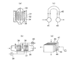
(a)図7(a)に示されるように、タンク31中に収容された水のプールに浸漬された熱交換ユニット32中に高温ガスを通過させるもので、排ガスダクト33は入側で複数のチューブ34に分岐して水中に浸漬され、出側で一本のダクト35に集められる。排ガスダクト33に高温ガスを通すことで排ガスの熱がタンク31中の冷却水に伝えられる。
(A) As shown in FIG. 7 (a), a high-temperature gas is passed through a
(b)図7(b)に示されるように、シェル36中に複数のチューブ37に分岐した熱交換ユニット38を収容し、ポンプ39を用いてチューブ37に冷却水を通す。一方、シェル36中に高温の排ガスを通すことで、排ガスを熱交換ユニット38内の冷却水に伝える。高温になった冷却水は冷却塔40で再度冷やされ、循環使用される。
(B) As shown in FIG. 7B, a
(c)図7(c)に示されるように、高温の排ガス用ダクト41を多数のチューブ42に分岐させ、高温の排ガスを自然冷却した後、再び一本のダクト43として集める方式。
(C) As shown in FIG. 7C, a system in which the hot
(d)図7(d)に示されるように、複数の金属板44を一定間隔を空けて並列配置し、金属板44を挟んで形成された排ガス通路45に高温の排ガスを、空気通路46に冷却用の空気を流す方式。高温の排ガスの熱は熱交換ユニット47内の金属板44を介して冷却用の空気に伝えられる。
(D) As shown in FIG. 7 (d), a plurality of
ところで、近年、脱燐、脱硫を目的として、溶銑予備処理においてソーダ灰を精練剤として利用することが多い。しかし、ソーダ灰には潮解性があって、これを含むダストにより排ガス冷却装置が詰まり、操業不可能になることが往々にしてある。このガス冷却装置の詰まりは、ダストを回収して再利用を図ろうとする溶銑予備処理操業において大きな問題になっている。 By the way, in recent years, soda ash is often used as a scouring agent in hot metal pretreatment for the purpose of dephosphorization and desulfurization. However, soda ash is deliquescent, and dust containing it often clogs the exhaust gas cooling device, making it impossible to operate. This clogging of the gas cooling device has become a serious problem in hot metal pretreatment operations where dust is collected and reused.
この問題を解決するために特許文献1には、図7(d)に示される強制空冷方式の熱交換ユニットを用い、熱交換ユニットの金属板の温度が高温の排ガスの露点温度以下にならないように制御し、排ガス中のダストが排ガス通路に付着するのを防止する排ガス冷却装置が開示されている。
しかし、特許文献1に記載の冷却装置にあっては、冷却用の空気の流量を調整するために送風機の回転数を制御したり、熱交換ユニットの入側及び出側のダクトに開閉可能なダンパを設けたりする必要があるので冷却装置が複雑化する。また、熱交換ユニットの金属板を排ガスの露点温度以下に制御したのでは、熱交換の効率が低下してしまう。
However, in the cooling device described in
しかも、たとえソーダ灰を使わなくても、高温の排ガスを冷却するのに必要な熱交換ユニットの長さが長くなりすぎると、熱交換ユニットの排ガス通路に付着したダストを除去したり清掃したりするための気体噴射が行き届かなくなる。一定期間が経過すると、熱交換ユニットの排ガス通路が閉鎖してしまうので、操業を停止してのジェット洗浄等が必要になる。操業を停止してのメンテナンスは設備のダウンタイムを発生させる。 Moreover, even if soda ash is not used, if the length of the heat exchange unit required to cool the high-temperature exhaust gas becomes too long, dust attached to the exhaust gas passage of the heat exchange unit will be removed or cleaned. The gas injection to do is not perfect. When a certain period of time has elapsed, the exhaust gas passage of the heat exchange unit is closed, so that it is necessary to perform jet cleaning or the like after stopping the operation. Maintenance after shutting down operations causes equipment downtime.
そこで本発明は、熱交換ユニットが排ガス中のダストで閉鎖するのを防止できる排ガス冷却装置を提供することを目的とする。 Accordingly, an object of the present invention is to provide an exhaust gas cooling device that can prevent the heat exchange unit from being closed by dust in the exhaust gas.
上記課題を解決するために、請求項1に記載の発明は、溶銑予備処理時に発生する高温の排ガスを冷却する排ガス冷却装置において、高温の排ガスの熱を冷却用の空気に伝えられるように排ガス通路及び空気通路がプレートを挟んで交互に形成される複数のプレート型熱交換ユニットを、上下方向に積み重ねることなく水平方向に配列し、水平方向に配列された前記複数のプレート型熱交換ユニットそれぞれに、前記排ガス通路に付着するダストを吹き払うスートブロワを組み合わせる排ガス冷却装置である。
In order to solve the above-mentioned problem, the invention according to
請求項2に記載の発明は、請求項1に記載の排ガス冷却装置において、前記プレート型熱交換ユニットは、前記高温の排ガスと前記冷却用の空気の流れる方向が直交する直交式のプレート型熱交換ユニットであり、水平方向に配列された前記複数のプレート型熱交換ユニットには、水平方向に前記冷却用の空気が流されると共に、隣接する前記プレート型熱交換ユニットで前記高温の排ガスの流れる方向が上下反転するように、水平方向に配列された前記複数のプレート型熱交換ユニットに流される前記高温の排ガスが蛇行することを特徴とする。 According to a second aspect of the present invention, there is provided the exhaust gas cooling apparatus according to the first aspect, wherein the plate-type heat exchange unit is an orthogonal plate-type heat in which a flow direction of the high-temperature exhaust gas and the cooling air is orthogonal to each other. The cooling air flows in the horizontal direction in the plurality of plate-type heat exchange units arranged in a horizontal direction, and the high-temperature exhaust gas flows in the adjacent plate-type heat exchange units. The high-temperature exhaust gas flowing through the plurality of plate-type heat exchange units arranged in a horizontal direction meanders so that the direction is inverted up and down.
請求項3に記載の発明は、請求項1又は2に記載の排ガス冷却装置において、前記プレート型熱交換ユニットの上下方向の高さは、3000mm以下であることを特徴とする。 A third aspect of the present invention is the exhaust gas cooling apparatus according to the first or second aspect, wherein the plate-type heat exchange unit has a vertical height of 3000 mm or less.
請求項4に記載の発明は、請求項1ないし3のいずれかに記載の排ガス冷却装置において、前記スートブロワは、前記プレート型熱交換ユニットの上部に配置されたランスを水平方向に移動させながら前記プレート型熱交換ユニットの前記排ガス通路に圧縮空気を噴射することを特徴とする。 According to a fourth aspect of the present invention, in the exhaust gas cooling apparatus according to any one of the first to third aspects, the soot blower moves the lance disposed above the plate-type heat exchange unit in the horizontal direction. Compressed air is injected into the exhaust gas passage of the plate type heat exchange unit.
排ガスを冷却するのに必要な伝熱面積を複数のプレート型熱交換ユニットによって確保し、この複数のプレート型熱交換ユニットを上下方向に積み重ねるのではなく、水平方向に配列することで、各プレート型熱交換ユニットの高さを抑制することができ、スートブロワを用いた気体噴射を各プレート型熱交換ユニットの全体に行き届かせることができる。したがって、プレート型熱交換ユニットがダストで閉鎖するのを防止することができる。 By securing the heat transfer area required to cool the exhaust gas with multiple plate heat exchange units and arranging the multiple plate heat exchange units in the horizontal direction instead of stacking them vertically, each plate The height of the mold heat exchange unit can be suppressed, and the gas injection using the soot blower can reach the entire plate type heat exchange unit. Therefore, it is possible to prevent the plate-type heat exchange unit from being closed with dust.
以下、添付図面を参照しながら本発明の実施形態を説明する。高炉で作られる溶銑は混銑車によって製鋼工場に輸送される。高炉の装入原料や操業条件によって溶銑成分にはかなりの変動が認められ、必ずしも次の製鋼工程に適した成分組成であるとは限らない。製鋼工程で要求される溶銑の成分組成は、最終の溶鋼の目標成分組成や製鋼工程、生産能率によって異なってくる。そこで溶銑の成分組成、製鋼精練方式、生産鋼種などに応じて適宜に溶銑の予備処理を行う必要がある。 Hereinafter, embodiments of the present invention will be described with reference to the accompanying drawings. Hot metal made in the blast furnace is transported to a steel factory by a kneading car. The hot metal component varies considerably depending on the raw materials and operating conditions of the blast furnace, and the component composition is not necessarily suitable for the next steelmaking process. The component composition of the hot metal required in the steelmaking process varies depending on the target component composition, steelmaking process, and production efficiency of the final molten steel. Therefore, it is necessary to appropriately perform hot metal pretreatment according to the composition of the hot metal, the steelmaking refining method, the production steel type, and the like.
溶銑の予備処理は、製鋼工場内に設けられた予備処理のための専用設備によって行われる。混銑車は予備処理のための処理ステーションに移動される。図1に示されるように、処理ステーションにおいて混銑車1には酸素源や精練剤を吹き込むためのランス2が挿入される。
The hot metal pretreatment is carried out by dedicated equipment for pretreatment provided in the steelmaking factory. The chaotic vehicle is moved to a processing station for preliminary processing. As shown in FIG. 1, a
図2は排ガス処理装置の概略図である。溶銑予備処理時に混銑車1から酸化鉄のダストを含んだ排ガスが発生する。予備処理ステーション3からブロワ4に吸引された排ガスは、ダクト5に集められ、排ガス冷却装置6により冷却される。そして、所定の温度にて集塵機7に集められる。
FIG. 2 is a schematic view of the exhaust gas treatment apparatus. During the hot metal pretreatment, exhaust gas containing iron oxide dust is generated from the
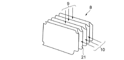
図3に示されるように、排ガス冷却装置6には複数のプレート型熱交換ユニット8が組み込まれる。図3には単一のプレート型熱交換ユニット8が示されている。プレート型熱交換ユニット8には、平行に配列された複数枚の金属板21を介して排ガス通路9と空気通路10とが交互に形成される。排ガス通路9には混銑車1から発生する高温の排ガスが流される。空気通路10には冷却用の空気が流される。排ガスが流れる方向と空気が流れる方向とは互いに直交する。高温の排ガスの熱は金属板21を介して冷却用の空気に伝えられる。
As shown in FIG. 3, a plurality of plate-type
図4は排ガス冷却装置6の側面図を示す。排ガス冷却装置6には、複数のプレート型熱交換ユニット8が上下方向に積み重ねることなく水平方向に配列される。この実施形態においては、排ガス冷却装置6の側方からみて合計四つのプレート型熱交換ユニット8が水平方向に一列に並べられる。複数のプレート型熱交換ユニット8の伝熱面積を合算することで、高温の排ガスを冷却するのに必要な伝熱面積が確保される。各プレート型熱交換ユニット8の高さは3000mm以下に設定される。
FIG. 4 shows a side view of the exhaust gas cooling device 6. In the exhaust gas cooling device 6, a plurality of plate-type
水平方向に配列された四つのプレート型熱交換ユニット8には水平方向に冷却用の空気が流される。左側のNo.1のプレート型熱交換ユニット8aに空気の入口11が形成される。右側のNo.4のプレート型熱交換ユニット8dに空気の出口12が形成される。冷却用の空気は、No.1のプレート型熱交換ユニット8aからNo.4のプレート型熱交換ユニット8dまで順番に通過する。
Cooling air flows in the horizontal direction through the four plate-type
一方、各プレート型熱交換ユニット8には、上下方向に高温の排ガスが流される。隣接するプレート型熱交換ユニット8で高温の排ガスが流れる方向が反転するように、水平方向に配列された複数のプレート型熱交換ユニット8に流される高温の排ガスが蛇行する。No.4のプレート型熱交換ユニット8dの上部には、排ガスの入口13が形成される。No.1のプレート型熱交換ユニット8aの上部には、排ガスの出口14が形成される。No.4のプレート型熱交換ユニット8dの下部とNo.3のプレート型熱交換ユニット8cの下部とは排ガスダクト15によって接続される。No.3のプレート型熱交換ユニット8cの上部とNo.2のプレート型熱交換ユニット8bの上部も排ガスダクト16によって接続され、No.2のプレート型熱交換ユニット8bの下部とNo.1のプレート型熱交換ユニット8aの下部も排ガスダクト17によって接続される。No.1〜No.4のプレート型熱交換ユニット8a〜8dに水平方向に冷却用の空気を流すと共に、上下方向に高温の排ガスを流すことで、高温の排ガスの熱が各熱交換ユニット8の金属板21を介して冷却用の空気に伝えられる。空気によって冷却された排ガスは、排ガスの出口14から排出される。
On the other hand, high-temperature exhaust gas flows through each plate-type
プレート型熱交換ユニット8の排ガス通路9にはダストが付着する。排ガス通路9に付着したダストを吹き払うために、各プレート型熱交換ユニット8の上部にはスートブロワ18が組み合わされる。スートブロワ18はプレート型熱交換ユニット8の排ガス通路9に上下方向に圧縮空気を噴射する。湿気は詰まりを助長するおそれがあるが、圧縮空気の替わりに蒸気を噴射してもよい。
Dust adheres to the exhaust gas passage 9 of the plate type
図6はスートブロワ及びプレート型熱交換ユニット8の平面図を示す。この実施形態では、左右方向に四列、奥行方向に四段、合計十六個のプレート型熱交換ユニット8が設けられる。スートブロワ18は一対のプレート型熱交換ユニット8に対して一つ設けられる。各スートブロワ18には、ランス19が設けられている。ランス19は圧縮空気を供給するための供給源、及び圧縮空気の圧力を調整するための圧力調整機構に接続される。ランス19の先端には圧縮空気を噴射するための複数のノズル19aが設けられる。左右方向の二個のプレート型熱交換ユニット8を行き来できるように、ランス19は駆動源によって軸線方向に移動される。ノズル19aが回転することによってプレート型熱交換ユニット8の上下方向に圧縮空気を噴射しつつ、ノズル19aを左右方向に移動させることで、一対のプレート型熱交換ユニット8の全体に圧縮空気を行き渡らせることができる。
FIG. 6 is a plan view of the soot blower and the plate type
プレート型熱交換ユニットの高さを3000mm以下にすることによって、清掃のためのスートブロワ18によるエアー噴射をプレート型熱交換ユニット8の排ガス通路9上下方向の全体に行き届かせることができる。したがって、排ガス通路へのダストの付着を防止することができる。また、これにより溶銑予備処理の操業を停止してまでプレート型熱交換ユニット8を清掃する必要もなくなり、ダスト付着防止を継続しながら安定的に脱燐処理操業を継続できる。
By setting the height of the plate type heat exchange unit to 3000 mm or less, the air injection by the
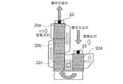
図5は比較例としてプレート型熱交換ユニットを上下方向に積み重ねた例を示す。図中左側に三段のプレート型熱交換ユニット22a〜22cが積み重ねられ、右側に一段のプレート型熱交換ユニット22dが配置される。プレート型熱交換ユニット22a〜22dには、水平方向に冷却用の空気が流されると共に、上下方向に高温の排ガスが流される。ここで、最上段のNo.1のプレート型熱交換ユニット22aを通過した空気は蛇行して、中段のNo.2のプレート型熱交換ユニット22bを通過し、再び蛇行して下段のNo.3のプレート型熱交換ユニット22cを通過する。そして、右側のNo.4のプレート型熱交換ユニット22dを通過する。一方、高温の排ガスはNo.4のプレート型熱交換ユニット22dを上から下に向かって通過した後、反転してNo.3からNo.1のプレート型熱交換ユニット22a〜22cを下から上に向かって通過する。スートブロア23は三段に積み重ねられた左側の三つのプレート型熱交換ユニット22a〜22cの上部に一つ、右側のプレート型熱交換ユニット22dの上部に一つ設けられる。この比較例においては、左側の三つのプレート型熱交換ユニット22a〜22cの上部に設けたスートブロア23のエアー噴射が最下段のプレート型熱交換ユニット22cまで行き届かず、一定期間が経過すると最下段のプレート型熱交換ユニット22cの排ガス通路が閉鎖してしまう。
FIG. 5 shows an example in which plate-type heat exchange units are stacked in the vertical direction as a comparative example. In the drawing, three stages of plate-type
なお、本発明は上記実施形態に限られることなく、本発明の要旨を変更しない範囲で様々な実施形態に変更可能である。たとえば、プレート型熱交換ユニットは排ガスの流れと空気の流れが直交する直交式に限られることなく、排ガスの流れと空気の流れが対向する向流式や、同一方向の並流式のものが用いられてもよい。 In addition, this invention is not restricted to the said embodiment, It can change into various embodiment in the range which does not change the summary of this invention. For example, the plate type heat exchange unit is not limited to the orthogonal type in which the flow of exhaust gas and the flow of air are orthogonal, but the counter flow type in which the flow of exhaust gas and the air flow are opposite, or the parallel flow type in the same direction May be used.
1…混銑車
6…排ガス冷却装置
8…プレート型熱交換ユニット
8a〜8d…No.1〜No.4プレート型熱交換ユニット
9…排ガス通路
10…空気通路
18…スートブロワ
21…金属板(プレート)
DESCRIPTION OF
Claims (4)
高温の排ガスの熱を冷却用の空気に伝えられるように排ガス通路及び空気通路がプレートを挟んで交互に形成される複数のプレート型熱交換ユニットを、上下方向に積み重ねることなく水平方向に配列し、
水平方向に配列された前記複数のプレート型熱交換ユニットそれぞれに、前記排ガス通路に付着するダストを吹き払うスートブロワを組み合わせる排ガス冷却装置。 In the exhaust gas cooling device that cools the hot exhaust gas generated during hot metal pretreatment,
A plurality of plate-type heat exchange units, in which the exhaust gas passages and air passages are alternately formed across the plates so that the heat of the hot exhaust gas can be transmitted to the cooling air, are arranged in a horizontal direction without being stacked vertically. ,
An exhaust gas cooling apparatus in which a plurality of plate-type heat exchange units arranged in a horizontal direction are combined with a soot blower that blows off dust adhering to the exhaust gas passage.
水平方向に配列された前記複数のプレート型熱交換ユニットには、水平方向に前記冷却用の空気が流されると共に、
隣接する前記プレート型熱交換ユニットで前記高温の排ガスの流れる方向が上下反転するように、水平方向に配列された前記複数のプレート型熱交換ユニットに流される前記高温の排ガスが蛇行することを特徴とする請求項1に記載の排ガス冷却装置。 The plate-type heat exchange unit is an orthogonal plate-type heat exchange unit in which the flow direction of the high-temperature exhaust gas and the cooling air is orthogonal to each other,
The plurality of plate-type heat exchange units arranged in the horizontal direction are supplied with the cooling air in the horizontal direction,
The high-temperature exhaust gas flowing in the plurality of plate-type heat exchange units arranged in a horizontal direction meanders so that the direction in which the high-temperature exhaust gas flows in the adjacent plate-type heat exchange unit is reversed upside down. The exhaust gas cooling device according to claim 1.
Priority Applications (1)
| Application Number | Priority Date | Filing Date | Title |
|---|---|---|---|
| JP2008252048A JP5755828B2 (en) | 2008-09-30 | 2008-09-30 | Exhaust gas cooling device |
Applications Claiming Priority (1)
| Application Number | Priority Date | Filing Date | Title |
|---|---|---|---|
| JP2008252048A JP5755828B2 (en) | 2008-09-30 | 2008-09-30 | Exhaust gas cooling device |
Publications (2)
| Publication Number | Publication Date |
|---|---|
| JP2010084958A true JP2010084958A (en) | 2010-04-15 |
| JP5755828B2 JP5755828B2 (en) | 2015-07-29 |
Family
ID=42249100
Family Applications (1)
| Application Number | Title | Priority Date | Filing Date |
|---|---|---|---|
| JP2008252048A Active JP5755828B2 (en) | 2008-09-30 | 2008-09-30 | Exhaust gas cooling device |
Country Status (1)
| Country | Link |
|---|---|
| JP (1) | JP5755828B2 (en) |
Cited By (2)
| Publication number | Priority date | Publication date | Assignee | Title |
|---|---|---|---|---|
| CN111850221A (en) * | 2019-04-25 | 2020-10-30 | 北京凯德恒源科技发展有限公司 | Deep recovery method of hot energy of molten iron pretreatment flue gas |
| SE544275C2 (en) * | 2016-03-24 | 2022-03-22 | Univ Nanjing Tech | Counter-flow fin plate heat exchanger for gas-gas heat exchange |
Families Citing this family (1)
| Publication number | Priority date | Publication date | Assignee | Title |
|---|---|---|---|---|
| CN106382824A (en) * | 2016-08-31 | 2017-02-08 | 上海浩用节能工程有限公司 | Novel tube heating furnace waste heat recovery system and method |
Citations (7)
| Publication number | Priority date | Publication date | Assignee | Title |
|---|---|---|---|---|
| JPS62299694A (en) * | 1986-06-19 | 1987-12-26 | Nippon Oil Co Ltd | Thermal conducting block for crossed type heat exchanger |
| JPH0791882A (en) * | 1993-09-27 | 1995-04-07 | Abb Gadelius Kk | Plate type heat exchanger having cleaning device |
| JPH0732388U (en) * | 1993-10-20 | 1995-06-16 | 栄産業株式会社 | Dust remover for plate heat exchanger |
| JPH10512361A (en) * | 1995-01-20 | 1998-11-24 | ポリブロック アクチェンゲゼルシャフト | Plate heat exchanger with wetting device |
| JP2000500560A (en) * | 1995-11-17 | 2000-01-18 | エア イノベーション スウェーデン アーベー | Heat exchanger |
| JP2004092935A (en) * | 2002-08-29 | 2004-03-25 | Jfe Steel Kk | Protective cover for heat exchanger panels and heat exchanger |
| WO2004042280A1 (en) * | 2002-11-05 | 2004-05-21 | Babcock-Hitachi Kabushiki Kaisha | Exhaust gas treating apparatus |
-
2008
- 2008-09-30 JP JP2008252048A patent/JP5755828B2/en active Active
Patent Citations (7)
| Publication number | Priority date | Publication date | Assignee | Title |
|---|---|---|---|---|
| JPS62299694A (en) * | 1986-06-19 | 1987-12-26 | Nippon Oil Co Ltd | Thermal conducting block for crossed type heat exchanger |
| JPH0791882A (en) * | 1993-09-27 | 1995-04-07 | Abb Gadelius Kk | Plate type heat exchanger having cleaning device |
| JPH0732388U (en) * | 1993-10-20 | 1995-06-16 | 栄産業株式会社 | Dust remover for plate heat exchanger |
| JPH10512361A (en) * | 1995-01-20 | 1998-11-24 | ポリブロック アクチェンゲゼルシャフト | Plate heat exchanger with wetting device |
| JP2000500560A (en) * | 1995-11-17 | 2000-01-18 | エア イノベーション スウェーデン アーベー | Heat exchanger |
| JP2004092935A (en) * | 2002-08-29 | 2004-03-25 | Jfe Steel Kk | Protective cover for heat exchanger panels and heat exchanger |
| WO2004042280A1 (en) * | 2002-11-05 | 2004-05-21 | Babcock-Hitachi Kabushiki Kaisha | Exhaust gas treating apparatus |
Cited By (2)
| Publication number | Priority date | Publication date | Assignee | Title |
|---|---|---|---|---|
| SE544275C2 (en) * | 2016-03-24 | 2022-03-22 | Univ Nanjing Tech | Counter-flow fin plate heat exchanger for gas-gas heat exchange |
| CN111850221A (en) * | 2019-04-25 | 2020-10-30 | 北京凯德恒源科技发展有限公司 | Deep recovery method of hot energy of molten iron pretreatment flue gas |
Also Published As
| Publication number | Publication date |
|---|---|
| JP5755828B2 (en) | 2015-07-29 |
Similar Documents
| Publication | Publication Date | Title |
|---|---|---|
| CN111020077B (en) | Liquid slag waste heat recovery system | |
| JP5755828B2 (en) | Exhaust gas cooling device | |
| CN110904320A (en) | Precision heat treatment production line for thin-wall special-shaped aluminum component | |
| CN202017036U (en) | Jet-flow cooling device for copper and copper alloy bright annealing furnace | |
| KR101126022B1 (en) | Apparatus for eliminating white-smoke | |
| CN105861768A (en) | Blast furnace cinder dry-process treatment device | |
| KR20190127037A (en) | A multi-stage heat exchange type drying system having a cleaning device | |
| JP2005529235A5 (en) | ||
| JPH09296998A (en) | Moving type bundle washing apparatus | |
| CN112575154B (en) | Plate heat treatment cooling system | |
| CN208995550U (en) | The cooling equipment of continuous heat-treating drier | |
| CN103221353B (en) | Nozzle for quenching unit | |
| CN106440854B (en) | A kind of tubular type blast-furnace soft water evaporative air-cooling system and its pipe scale processing method | |
| KR20100035838A (en) | Hybrid type cooling tower | |
| CN206469723U (en) | A kind of tubular type blast-furnace soft water evaporative air-cooling system | |
| CN106403652B (en) | It is a kind of using the shell-and-plate blast furnace evaporative air-cooling system of soft water airtight circulating cooling system and its plate dirt processing method | |
| RU2677555C2 (en) | Counterflow heat exchanger for dust-laden exhaust gas of metallurgical installations | |
| CN102673159A (en) | Recording apparatus | |
| KR101298728B1 (en) | Sensible heat collecting apparatus of furnace slag | |
| KR102015506B1 (en) | Iron removal device of continuous annealing furnace | |
| CN202328124U (en) | Waste heat boiler | |
| CN205676488U (en) | A kind of dry processing device of blast furnace cinder | |
| JP4418053B2 (en) | Continuous annealing furnace | |
| CN108660269A (en) | A kind of jet stream granulation spray gun and slag granulating heat-exchanger rig | |
| CN210885936U (en) | Dry quenching coke once dust removal box type coke powder cooling device |
Legal Events
| Date | Code | Title | Description |
|---|---|---|---|
| A621 | Written request for application examination |
Free format text: JAPANESE INTERMEDIATE CODE: A621 Effective date: 20110824 |
|
| A131 | Notification of reasons for refusal |
Free format text: JAPANESE INTERMEDIATE CODE: A131 Effective date: 20130716 |
|
| A521 | Request for written amendment filed |
Free format text: JAPANESE INTERMEDIATE CODE: A523 Effective date: 20130912 |
|
| A02 | Decision of refusal |
Free format text: JAPANESE INTERMEDIATE CODE: A02 Effective date: 20140114 |
|
| A521 | Request for written amendment filed |
Free format text: JAPANESE INTERMEDIATE CODE: A523 Effective date: 20140403 |
|
| A521 | Request for written amendment filed |
Free format text: JAPANESE INTERMEDIATE CODE: A523 Effective date: 20140416 |
|
| A521 | Request for written amendment filed |
Free format text: JAPANESE INTERMEDIATE CODE: A523 Effective date: 20140416 |
|
| A911 | Transfer to examiner for re-examination before appeal (zenchi) |
Free format text: JAPANESE INTERMEDIATE CODE: A911 Effective date: 20140512 |
|
| A912 | Re-examination (zenchi) completed and case transferred to appeal board |
Free format text: JAPANESE INTERMEDIATE CODE: A912 Effective date: 20140620 |
|
| A61 | First payment of annual fees (during grant procedure) |
Free format text: JAPANESE INTERMEDIATE CODE: A61 Effective date: 20150528 |
|
| R150 | Certificate of patent or registration of utility model |
Ref document number: 5755828 Country of ref document: JP Free format text: JAPANESE INTERMEDIATE CODE: R150 |
|
| R250 | Receipt of annual fees |
Free format text: JAPANESE INTERMEDIATE CODE: R250 |
|
| R250 | Receipt of annual fees |
Free format text: JAPANESE INTERMEDIATE CODE: R250 |
|
| R250 | Receipt of annual fees |
Free format text: JAPANESE INTERMEDIATE CODE: R250 |