JP2010084775A - Tensioning device - Google Patents
Tensioning device Download PDFInfo
- Publication number
- JP2010084775A JP2010084775A JP2008250886A JP2008250886A JP2010084775A JP 2010084775 A JP2010084775 A JP 2010084775A JP 2008250886 A JP2008250886 A JP 2008250886A JP 2008250886 A JP2008250886 A JP 2008250886A JP 2010084775 A JP2010084775 A JP 2010084775A
- Authority
- JP
- Japan
- Prior art keywords
- chain
- arm
- tensioning device
- tensioner
- tensioner arm
- Prior art date
- Legal status (The legal status is an assumption and is not a legal conclusion. Google has not performed a legal analysis and makes no representation as to the accuracy of the status listed.)
- Granted
Links
Images


Classifications
-
- F—MECHANICAL ENGINEERING; LIGHTING; HEATING; WEAPONS; BLASTING
- F16—ENGINEERING ELEMENTS AND UNITS; GENERAL MEASURES FOR PRODUCING AND MAINTAINING EFFECTIVE FUNCTIONING OF MACHINES OR INSTALLATIONS; THERMAL INSULATION IN GENERAL
- F16H—GEARING
- F16H7/00—Gearings for conveying rotary motion by endless flexible members
- F16H7/08—Means for varying tension of belts, ropes, or chains
- F16H2007/0802—Actuators for final output members
- F16H2007/0808—Extension coil springs
-
- F—MECHANICAL ENGINEERING; LIGHTING; HEATING; WEAPONS; BLASTING
- F16—ENGINEERING ELEMENTS AND UNITS; GENERAL MEASURES FOR PRODUCING AND MAINTAINING EFFECTIVE FUNCTIONING OF MACHINES OR INSTALLATIONS; THERMAL INSULATION IN GENERAL
- F16H—GEARING
- F16H7/00—Gearings for conveying rotary motion by endless flexible members
- F16H7/08—Means for varying tension of belts, ropes, or chains
- F16H7/0848—Means for varying tension of belts, ropes, or chains with means for impeding reverse motion
- F16H2007/0853—Ratchets
-
- F—MECHANICAL ENGINEERING; LIGHTING; HEATING; WEAPONS; BLASTING
- F16—ENGINEERING ELEMENTS AND UNITS; GENERAL MEASURES FOR PRODUCING AND MAINTAINING EFFECTIVE FUNCTIONING OF MACHINES OR INSTALLATIONS; THERMAL INSULATION IN GENERAL
- F16H—GEARING
- F16H7/00—Gearings for conveying rotary motion by endless flexible members
- F16H7/08—Means for varying tension of belts, ropes, or chains
- F16H2007/0863—Finally actuated members, e.g. constructional details thereof
- F16H2007/0874—Two or more finally actuated members
-
- F—MECHANICAL ENGINEERING; LIGHTING; HEATING; WEAPONS; BLASTING
- F16—ENGINEERING ELEMENTS AND UNITS; GENERAL MEASURES FOR PRODUCING AND MAINTAINING EFFECTIVE FUNCTIONING OF MACHINES OR INSTALLATIONS; THERMAL INSULATION IN GENERAL
- F16H—GEARING
- F16H7/00—Gearings for conveying rotary motion by endless flexible members
- F16H7/08—Means for varying tension of belts, ropes, or chains
- F16H2007/0889—Path of movement of the finally actuated member
- F16H2007/0893—Circular path
-
- F—MECHANICAL ENGINEERING; LIGHTING; HEATING; WEAPONS; BLASTING
- F16—ENGINEERING ELEMENTS AND UNITS; GENERAL MEASURES FOR PRODUCING AND MAINTAINING EFFECTIVE FUNCTIONING OF MACHINES OR INSTALLATIONS; THERMAL INSULATION IN GENERAL
- F16H—GEARING
- F16H7/00—Gearings for conveying rotary motion by endless flexible members
- F16H7/08—Means for varying tension of belts, ropes, or chains
- F16H2007/0889—Path of movement of the finally actuated member
- F16H2007/0897—External to internal direction
Abstract
Description
本発明は、チェーンに張力を発生させるためのテンショニング装置に関し、詳細には、芯間距離の短いチェーン駆動装置に好適の装置に関する。 The present invention relates to a tensioning device for generating tension in a chain, and more particularly to a device suitable for a chain driving device having a short inter-center distance.
運転中に生じるチェーンの弛みを除去してチェーンに張力を発生させるために、従来より、テンショニング装置が用いられている。テンショニング装置は、一般に、チェーンの弛み側スパンに配設され、枢支端の回りを回動自在に設けられるとともに、チェーンが摺動するチェーン摺動面を有するテンショナアームと、テンショナアームのチェーン摺動面がチェーンの弛み側スパンに当接するよう、テンショナアームを弛み側スパンに向かって押圧するテンショナとを備えている。この場合、チェーンの張り側スパンには、一般に、チェーンの走行をガイドするためのチェーンガイドが設けられている。 Conventionally, a tensioning device has been used to remove chain slack that occurs during operation and generate tension in the chain. The tensioning device is generally disposed on the slack side span of the chain and is provided so as to be rotatable around the pivot end, and has a chain sliding surface on which the chain slides, and a chain of the tensioner arm A tensioner is provided that presses the tensioner arm toward the slack side span so that the sliding surface comes into contact with the slack side span of the chain. In this case, a chain guide for guiding the travel of the chain is generally provided on the tension side span of the chain.
また、チェーンの複数のスパンに同時に緊張力を作用させるテンショニング装置も提案されている。このテンショニング装置は、例えば特開2006−329418号公報に示すように、チェーンの張り側スパンおよび弛み側スパンの外側にそれぞれ配設され、各々枢支端の回りを回動自在な第1、第2のテンショナアームと、各テンショナアーム間に配設されるとともに互いにピン連結された第1、第2のリンク部材からなり、各テンショナアーム間を連結するリンク機構と、ピストン先端が各リンク部材の連結ピンに連結されたテンショナとを有している(図4および図7参照)。 There has also been proposed a tensioning device that simultaneously applies tension to a plurality of spans of a chain. For example, as shown in Japanese Patent Application Laid-Open No. 2006-329418, the tensioning device is disposed on the outside of the tension side slack side and the slack side span of the chain, respectively, and is capable of rotating around the pivot end. A link mechanism that includes a second tensioner arm and first and second link members that are disposed between the tensioner arms and are pin-coupled to each other. And a tensioner connected to the connecting pin (see FIGS. 4 and 7).
この場合には、チェーンの摩耗によりチェーンが伸びたときには、テンショナのピストンが突出して、各リンク部材の連結ピンを押圧する。これにより、各リンク部材は、その挟角が減少する向きに互いに回動する(上記公報の図5参照)。その結果、各テンショナアームが対応するチェーンスパンに押接して、各チェーンスパンの弛みが除去されるようになっている。
しかしながら、上記公報に示すテンショニング装置は、エンジンのドライブスプロケット(クランクスプロケット)およびドリブンスプロケット(カムスプロケット)間を駆動連結するチェーンつまりタイミングチェーンに好適の装置であって、この場合、各スプロケット間の芯間距離は比較的長い。したがって、当該公報に示す装置の場合、各チェーンスパン間の内部スペースが比較的長く、このため、当該内部スペース内にテンショナを配置することが可能である。 However, the tensioning device shown in the above publication is a device suitable for a chain that drives and connects between a drive sprocket (crank sprocket) and a driven sprocket (cam sprocket) of an engine, that is, a timing chain. The distance between the cores is relatively long. Therefore, in the case of the device shown in the publication, the internal space between the chain spans is relatively long, and therefore it is possible to arrange the tensioner in the internal space.
これに対して、エンジンの補機駆動装置やオイルポンプ駆動装置などに用いられるチェーンの場合、芯間距離が短い。この場合には、各チェーンスパンの間に十分な内部スペースを確保できないので、上記公報に記載されたようなテンショニング装置を採用することは困難である。 On the other hand, in the case of a chain used for an engine accessory drive device, an oil pump drive device, or the like, the center distance is short. In this case, since a sufficient internal space cannot be secured between the chain spans, it is difficult to employ a tensioning device as described in the above publication.
本発明は、このような従来の実情に鑑みてなされたもので、本発明が解決しようとする課題は、エンジンの補機駆動装置やオイルポンプ駆動装置のように芯間距離の短いチェーン駆動装置において、複数のチェーンスパンに同時に緊張力を作用させることができるテンショニング装置を簡単な構造で実現することにある。 The present invention has been made in view of such conventional circumstances, and the problem to be solved by the present invention is a chain drive device having a short inter-center distance such as an engine accessory drive device and an oil pump drive device. In other words, a tensioning device that can simultaneously apply tension to a plurality of chain spans is realized with a simple structure.
請求項1の発明に係るテンショニング装置は、第1、第2のチェーンスパンを有するチェーンに緊張力を作用させるための装置である。第1のテンショナアームは、第1のチェーンスパンの外側において当該第1のチェーンスパンに沿って弧状に延設されるとともに、支軸により枢支される枢支端と自由端とを有し、チェーンが摺動する第1のアーム部と、第1のアーム部に一体に設けられるとともに、第1、第2のチェーンスパン間の内部空間に向かって張り出す第1のフランジ部とを有している。第2のテンショナアームは、第2のチェーンスパンの外側において当該第2のチェーンスパンに沿って弧状に延設されるとともに、支軸により枢支される枢支端と自由端とを有し、チェーンが摺動する第2のアーム部と、第2のアーム部に一体に設けられ、第1、第2のチェーンスパン間の内部空間に向かって張り出すとともに、第1のフランジ部とオーバラップする第2のフランジ部とを有している。また、当該テンショニング装置は、第1のテンショナアームの第1のフランジ部および第2のテンショナアームの第2のフランジ部とのオーバラップ部分に設けられ、第1、第2のフランジ部を回動自在に連結する連結部と、第1のテンショナアームの自由端を第1のチェーンスパンの側に向かって付勢する付勢手段とを備えている。そして、付勢手段が第1のテンショナアームの自由端を第1のチェーンスパンの側に向かって付勢するとき、連結部を介して、第1のテンショナアームの第1のフランジ部が第2のテンショナアームの第2のフランジ部を回動させて、第2のテンショナアームの第2のアーム部を第2のチェーンスパンの側に移動させるようになっている。 A tensioning device according to a first aspect of the present invention is a device for applying tension to a chain having first and second chain spans. The first tensioner arm extends in an arc shape along the first chain span outside the first chain span, and has a pivot end and a free end pivotally supported by the support shaft, A first arm portion on which the chain slides, and a first flange portion which is provided integrally with the first arm portion and projects toward the internal space between the first and second chain spans. ing. The second tensioner arm extends in an arc shape along the second chain span outside the second chain span, and has a pivot end and a free end pivotally supported by the support shaft, A second arm portion on which the chain slides, and a second arm portion that are integrally provided on the second arm portion, project toward the internal space between the first and second chain spans, and overlap with the first flange portion And a second flange portion. The tensioning device is provided at an overlap portion between the first flange portion of the first tensioner arm and the second flange portion of the second tensioner arm, and rotates the first and second flange portions. A connecting portion that is movably connected and a biasing means that biases the free end of the first tensioner arm toward the first chain span. When the urging means urges the free end of the first tensioner arm toward the first chain span, the first flange portion of the first tensioner arm is second through the connecting portion. The second flange portion of the tensioner arm is rotated to move the second arm portion of the second tensioner arm toward the second chain span.
請求項1の発明においては、当該テンショニング装置の運転時には、付勢手段が第1のテンショナアームの自由端を第1のチェーンスパンの側に向かって付勢する。すると、第1のテンショナアームの第1のアーム部が枢支端の回りを回動して、第1のアーム部が第1のチェーンスパンを押接する。これにより、第1のチェーンスパンの弛みが除去される。また、第1のアーム部の回動時には、第1のフランジ部、連結部および第2のフランジ部を介して、第2のテンショナアームの第2のアーム部が枢支端の回りを回動して、第2のアーム部が第2のチェーンスパンを押接する。これにより、第2のチェーンスパンの弛みが除去される。このようにして、チェーンに緊張力を作用させることができる。 In the first aspect of the invention, during operation of the tensioning device, the biasing means biases the free end of the first tensioner arm toward the first chain span. Then, the first arm portion of the first tensioner arm rotates around the pivot end, and the first arm portion presses the first chain span. Thereby, the slack of the first chain span is removed. Further, when the first arm portion is rotated, the second arm portion of the second tensioner arm is rotated around the pivot end via the first flange portion, the connecting portion, and the second flange portion. Then, the second arm portion presses against the second chain span. Thereby, the slackness of the second chain span is removed. In this way, tension can be applied to the chain.
この場合には、付勢手段としてのテンショナが、第1、第2のチェーンスパン間の内部空間に配置されないので、エンジンの補機駆動装置やオイルポンプ駆動装置のように芯間距離の短いチェーン駆動装置において各チェーンスパン間に十分な内部スペースが確保できない場合に好適のテンショニング装置を実現できる。また、この場合には、第1、第2のテンショナアームは、第1、第2のフランジ部を介して連結部により連結されているだけなので、構造を簡略化できる。 In this case, since the tensioner as the urging means is not arranged in the internal space between the first and second chain spans, a chain having a short inter-center distance such as an engine accessory driving device or an oil pump driving device of the engine. When the drive device cannot secure a sufficient internal space between the chain spans, a suitable tensioning device can be realized. Further, in this case, the first and second tensioner arms are simply connected by the connecting portion via the first and second flange portions, so that the structure can be simplified.
請求項2の発明では、請求項1において、連結部が、第2のフランジ部のオーバラップ部分に貫通形成された長孔と、第1のフランジ部に突設されかつ長孔に係止されるとともに、長孔に沿ってスライド自在な突設部とから構成されている。 According to a second aspect of the present invention, in the first aspect, the connecting portion includes a long hole penetratingly formed in the overlap portion of the second flange portion, and a projection protruding from the first flange portion and locked to the long hole. And a projecting portion that is slidable along the long hole.
この場合には、連結部が、例えばピンやネジ等の突設部と長孔から構成されるので、連結部の構成を簡略化でき、これにより、装置全体の構造をさらに簡略化できる。 In this case, since the connecting portion is composed of a protruding portion such as a pin or a screw and a long hole, for example, the structure of the connecting portion can be simplified, thereby further simplifying the structure of the entire apparatus.
請求項3の発明では、請求項1において、連結部が、第1のフランジ部のオーバラップ部分に貫通形成された第1の長孔と、第2のフランジ部のオーバラップ部分に貫通形成され、第1の長孔と一部オーバラップする第2の長孔と、当該テンショニング装置の据付側に設けられ、第1、第2の長孔と一部オーバラップしつつ、第1、第2の長孔と交差する方向に延びる第3の長孔と、第3の長孔から突設しつつ第1ないし第3の長孔のオーバラップ部分に係止されるとともに、第1、第2のフランジ部の回動時に第1ないし第3の長孔のオーバラップ部分に沿ってスライド自在な突設部とから構成されている。 According to a third aspect of the present invention, in the first aspect, the connecting portion is formed by penetrating the first elongated hole formed in the overlap portion of the first flange portion and the overlap portion of the second flange portion. A second elongated hole partially overlapping with the first elongated hole, and provided on the installation side of the tensioning device, while partially overlapping with the first and second elongated holes, A third elongated hole extending in a direction intersecting with the second elongated hole, and is locked to an overlap portion of the first to third elongated holes while projecting from the third elongated hole. And a projecting portion that is slidable along the overlap portion of the first to third elongated holes when the second flange portion is rotated.
この場合には、第1、第2のテンショナアームの回動時において、突設部が第1ないし第3の長孔に沿って移動する際には、突設部は常時、第1ないし第3の長孔のオーバラップ部分で係止されるので、運転時に第2のチェーンスパンから第2のテンショナアームに過大な押付力が作用した場合でも、第2のテンショナアームが第2のチェーンスパンから離れる側に回動するのを確実に規制できる。 In this case, when the projecting portion moves along the first to third elongated holes during the rotation of the first and second tensioner arms, the projecting portion is always in the first to second directions. 3, the second tensioner arm is locked to the second chain span even if an excessive pressing force is applied to the second tensioner arm from the second chain span during operation. Rotation to the side away from the can be reliably controlled.
請求項4の発明では、請求項1において、連結部が、第1、第2のフランジ部にそれぞれ形成され、互いに噛み合う第1、第2の歯部から構成されている。 According to a fourth aspect of the present invention, in the first aspect, the connecting portion is formed of first and second tooth portions that are formed on the first and second flange portions, respectively, and mesh with each other.
この場合、第1のテンショナアームの回動時には、第1の歯部と噛み合う第2の歯部が回転することにより、第2のテンショナアームが回動する。この場合、連結部の第1、第2の歯部は常時噛み合っているので、運転時に第2のチェーンスパンから第2のテンショナアームに過大な押付力が作用した場合でも、第2のテンショナアームが第2のチェーンスパンから離れる側に回動するのを確実に規制できる。 In this case, when the first tensioner arm is rotated, the second tensioner arm is rotated by the rotation of the second tooth portion engaged with the first tooth portion. In this case, since the first and second tooth portions of the connecting portion are always meshed with each other, even if an excessive pressing force acts on the second tensioner arm from the second chain span during operation, the second tensioner arm Can be reliably restricted from rotating to the side away from the second chain span.
請求項5の発明では、請求項1において、付勢手段が、第1のチェーンスパンの外側に配置され、伸退自在なピストンを有するテンショナである。 According to a fifth aspect of the present invention, in the first aspect, the biasing means is a tensioner that is disposed outside the first chain span and has a retractable piston.
請求項6の発明では、請求項1において、付勢手段が、第1のフランジ部に一端が係止されかつ第2のフランジ部に他端が係止されたスプリングである。 According to a sixth aspect of the present invention, in the first aspect, the urging means is a spring having one end locked to the first flange portion and the other end locked to the second flange portion.
この場合には、スプリングの引張力により、第1、第2のフランジ部を介して、第1、第2のテンショナアームがそれぞれ第1、第2のチェーンスパンに接近する側に回動する。この場合には、付勢手段が単一のスプリングから構成されるので、付勢手段ひいては装置全体の構造を簡略化できる。 In this case, the first and second tensioner arms rotate to the side approaching the first and second chain spans via the first and second flange portions by the tensile force of the spring, respectively. In this case, since the urging means is composed of a single spring, the structure of the urging means and thus the entire apparatus can be simplified.
請求項7の発明では、請求項1において、第1または第2のテンショナアームの支軸には、第1または第2のテンショナアームの第1、第2のチェーンスパンの側への移動を許容しつつ逆方向への移動を規制するためのラチェット機構が設けられている。 According to a seventh aspect of the present invention, in the first aspect, the support shaft of the first or second tensioner arm is allowed to move the first or second tensioner arm toward the first or second chain span. However, a ratchet mechanism for restricting movement in the reverse direction is provided.
この場合には、運転時に第1または第2のチェーンスパンに過大な押付力が作用した場合でも、第1、第2のテンショナアームが第1、第2のチェーンスパンから離れる側に回動するのをラチェット機構により確実に防止できる。 In this case, even if an excessive pressing force is applied to the first or second chain span during operation, the first and second tensioner arms rotate away from the first and second chain spans. Can be reliably prevented by the ratchet mechanism.
請求項8の発明では、請求項1において、第1または第2のテンショナアームの支軸には、第1または第2のテンショナアームの第1、第2のチェーンスパンの側に付勢する捩じりコイルばねが設けられている。 According to an eighth aspect of the present invention, in the first aspect, the support shaft of the first or second tensioner arm has a screw for biasing toward the first or second chain span side of the first or second tensioner arm. A torsion coil spring is provided.
この場合には、付勢手段が捩じりコイルばねから構成されるので、付勢手段ひいては装置全体の構造を簡略化できる。 In this case, since the urging means is composed of a torsion coil spring, the structure of the urging means and the entire apparatus can be simplified.
以上のように、本発明に係るテンショニング装置によれば、第1、第2のチェーンスパンの外側にそれぞれ第1、第2のテンショナアームを配設し、第1、第2のテンショナアームにおける第1、第2のフランジ部を互いにオーバラップさせ、当該オーバラップ部分において第1、第2のフランジ部を連結部により回動自在に連結するとともに第1のテンショナアームの自由端を第1のチェーンスパンの側に向かって付勢する付勢手段を設けたので、運転時において、付勢手段が第1のテンショナアームの自由端を第1のチェーンスパンの側に向かって付勢すると、第1のテンショナアームの第1のアーム部が枢支端の回りを回動して、第1のアーム部が第1のチェーンスパンを押接し、これにより、第1のチェーンスパンの弛みが除去される。また、第1のアーム部の回動時には、第1のフランジ部、連結部および第2のフランジ部を介して、第2のテンショナアームの第2のアーム部が枢支端の回りを回動して、第2のアーム部が第2のチェーンスパンを押接し、これにより、第2のチェーンスパンの弛みが除去される。このようにして、チェーンに緊張力を作用させることができる。 As described above, according to the tensioning device according to the present invention, the first and second tensioner arms are disposed outside the first and second chain spans, respectively. The first and second flange portions are overlapped with each other, and the first and second flange portions are rotatably connected to each other at the overlap portion, and the free end of the first tensioner arm is connected to the first end. Since biasing means for biasing toward the chain span side is provided, when the biasing means biases the free end of the first tensioner arm toward the first chain span side during operation, The first arm portion of one tensioner arm pivots about the pivot end, and the first arm portion presses against the first chain span, thereby eliminating the slack in the first chain span. . Further, when the first arm portion is rotated, the second arm portion of the second tensioner arm is rotated around the pivot end via the first flange portion, the connecting portion, and the second flange portion. Then, the second arm portion presses against the second chain span, and thereby the slack of the second chain span is removed. In this way, tension can be applied to the chain.
この場合には、付勢手段としてのテンショナが、第1、第2のチェーンスパン間の内部空間に配置されないので、エンジンの補機駆動装置やオイルポンプ駆動装置のように芯間距離の短いチェーン駆動装置において各チェーンスパン間に十分な内部スペースが確保できない場合に好適のテンショニング装置を実現できる。また、この場合には、第1、第2のテンショナアームは、第1、第2のフランジ部を介して連結部により連結されているだけなので、構造を簡略化できる。 In this case, since the tensioner as the urging means is not arranged in the internal space between the first and second chain spans, a chain having a short inter-center distance such as an engine accessory driving device or an oil pump driving device of the engine. When the drive device cannot secure a sufficient internal space between the chain spans, a suitable tensioning device can be realized. Further, in this case, the first and second tensioner arms are simply connected by the connecting portion via the first and second flange portions, so that the structure can be simplified.
以下、本発明の実施例を添付図面に基づいて説明する。
〔第1の実施例〕
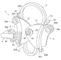
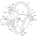
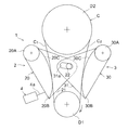
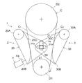
図1ないし図3Aは本発明の第1の実施例によるテンショニング装置を説明するための図であって、図1はテンショニング装置の全体斜視図、図2は図1において抜け止め用のナットを外した状態を示す図、図2Aは図2の模式図、図3はチェーンが伸びた状態におけるテンショニング装置の全体斜視図、図3Aは図3の模式図である。なお、図1、図2、図3においては、駆動スプロケットおよび従動スプロケットが省略された状態を示しており、図2Aおよび図3Aにおいては、これらのスプロケットを模式的に示している。
Embodiments of the present invention will be described below with reference to the accompanying drawings.
[First embodiment]
1 to 3A are views for explaining a tensioning device according to a first embodiment of the present invention. FIG. 1 is an overall perspective view of the tensioning device, and FIG. 2 is a nut for retaining in FIG. 2A is a schematic view of FIG. 2, FIG. 3 is an overall perspective view of the tensioning device in a state where the chain is extended, and FIG. 3A is a schematic view of FIG. 1, 2, and 3 show a state where the drive sprocket and the driven sprocket are omitted, and FIGS. 2A and 3A schematically show these sprockets.
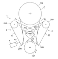
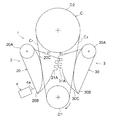
図1、図2および図2Aに示すように、このテンショニング装置1は、駆動スプロケットD1および従動スプロケットD2の周りに巻き掛けられたチェーンCに緊張力を作用させるための装置である。チェーンCは、好ましくは、エンジンの補機駆動装置やオイルポンプ駆動装置のように、駆動スプロケットおよび従動スプロケット間の芯間距離が短いチェーンである。チェーンCは、駆動スプロケットD1および従動スプロケットD2間に配設された第1、第2のチェーンスパンC1、C2を有している。ここでは、チェーンスパンC1が弛み側スパンであり、チェーンスパンC2が張り側スパンである。
As shown in FIGS. 1, 2 and 2A, the
テンショニング装置1は、第1のチェーンスパンC1の外側に配設され、第1のチェーンスパンC1に緊張力を作用させるための第1のテンショナアーム2と、第2のチェーンスパンC2の外側に配設され、第2のチェーンスパンC2に緊張力を作用させるための第2のテンショナアーム3とを備えている。
第1のテンショナアーム2は、第1のチェーンスパンC1に沿って弧状に延設されるとともに、支軸(図示せず)により枢支される枢支端20Aと自由端20Bとを有し、チェーンCが摺動する第1のアーム部20と、第1のアーム部20に一体に設けられるとともに、第1、第2のチェーンスパンC1、C2間の内部空間に向かって張り出す第1のフランジ部21とを有している。枢支端20Aには、貫通孔20aが形成されている。貫通孔20aには支軸が挿通しており、該支軸はエンジン側に固定されている。第1のアーム部20には、チェーンCの摺動面を有するシュー20Cが装着されている。
第2のテンショナアーム3は、第2のチェーンスパンC2に沿って弧状に延設されるとともに、支軸(図示せず)により枢支される枢支端30Aと自由端30Bとを有し、チェーンCが摺動する第2のアーム部30と、第2のアーム部30に一体に設けられ、第1、第2のチェーンスパンC1、C2間の内部空間に向かって張り出すとともに、第1のフランジ部21とオーバラップする第2のフランジ部31とを有している。枢支端30Aには、貫通孔30aが形成されている。貫通孔30aには支軸が挿通しており、該支軸はエンジン側に固定されている。第2のアーム部30には、チェーンCの摺動面を有するシュー30Cが装着されている。
第1、第2のフランジ部21、31のオーバラップ部分には、第1、第2のフランジ部21、31を回動自在に連結する連結部が設けられている。この連結部は、当該オーバラップ部分において、第2のフランジ部31に貫通形成された長孔31aと、第1のフランジ部21に一端が植設されかつ他端が第1のフランジ部21の面から突出するとともに、第2のフランジ部31の長孔31aに係合しかつ長孔31aに沿ってスライド自在な突設部22とから構成されている。突設部22は、ここでは、先端にネジ部が形成されており、該ネジ部には、ワッシャー23を介して、抜け止め用のナット24が螺合している。なお、突設部22はピンにより構成するようにしてもよい。
A connecting portion for rotatably connecting the first and
第1のテンショナアーム2の外側には、第1のテンショナアーム2の自由端20Bを第1のチェーンスパンC1の側に向かって付勢する付勢手段としてのテンショナ4が設けられている。テンショナ4は、伸退自在なピストン4aを有しており、ピストン4aの先端は、第1のテンショナアーム2の自由端20Bに圧接している。また、テンショナ4は、ピストン4aをスライド自在に収容するテンショナボディ40を有しており、テンショナボディ40は、これをエンジン側に取り付けるための取付孔40aを有している。テンショナ4は、油圧式または機械式のいずれのテンショナでもよい。
On the outside of the
上述のように構成されるテンショニング装置1の運転時には、テンショナ4のピストン4aが第1のテンショナアーム2の自由端20Bを第1のチェーンスパンC1の側に向かって付勢する。すると、第1のテンショナアーム2の第1のアーム部20が枢支端20Aの回りを図2A反時計回りに回動して、第1のアーム部20が第1のチェーンスパンC1を押接する。これにより、第1のチェーンスパンC1の弛みが除去される。
During operation of the
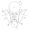
また、第1のアーム部20の回動時には、第1のフランジ部21も回動し、このとき、第1のフランジ部21に植設された突設部22が、第1のアーム部20の枢支端20Aの回りを図2A反時計回りに回動する。これにより、突設部22が係合する長孔31aを介して、第2のアーム部30が枢支端30Aの回りを図2A時計回りに回動する。このとき、図3、図3Aに示すように、突設部22は、長孔31a内において図示右端側に移動している。これにより、第2のアーム部30が第2のチェーンスパンC2を押接して、第2のチェーンスパンC2の弛みが除去される。このようにして、チェーンCに緊張力を作用させることができる。
In addition, when the
この場合には、テンショナ4が、第1、第2のチェーンスパンC1、C2間の内部空間に配置されていないので、エンジンの補機駆動装置やオイルポンプ駆動装置のように芯間距離の短いチェーン駆動装置において、各チェーンスパン間に十分な内部スペースが確保できない場合に好適のテンショニング装置を実現できる。また、この場合には、第1、第2のテンショナアーム2、3が、第1、第2のフランジ部21、31を介して連結部により連結されているだけであり、しかもこの場合の連結部が突設部22およびこれが係合する長孔31aから構成されているので、装置全体の構造を簡略化できる。
In this case, since the
〔第2の実施例〕
図4ないし図5Aは本発明の第2の実施例によるテンショニング装置を説明するための図であって、図4はテンショニング装置の模式図、図4Aは図4の一部拡大図、図5はチェーンが伸びた状態におけるテンショニング装置の模式図、図5Aは図5の一部拡大図である。なお、これらの図において、前記第1の実施例と同一符号は同一または相当部分を示している。
[Second Embodiment]
4 to 5A are views for explaining a tensioning device according to a second embodiment of the present invention. FIG. 4 is a schematic view of the tensioning device, FIG. 4A is a partially enlarged view of FIG. 5 is a schematic view of the tensioning device in a state where the chain is extended, and FIG. 5A is a partially enlarged view of FIG. In these drawings, the same reference numerals as those in the first embodiment denote the same or corresponding parts.
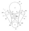
この第2の実施例では、連結部の構成が前記第1の実施例とは異なっている。すなわち、図4および図4Aに示すように、連結部は、第1のテンショナアーム2の第1のフランジ部21および第2のテンショナアーム2の第2のフランジ部31のオーバラップ部分において、第1のフランジ部21に貫通形成された第1の長孔21aと、第2のフランジ部31に貫通形成され、第1の長孔21aと一部オーバラップしつつ第1の長孔21aと交差する方向に延びる第2の長孔31aと、当該テンショニング装置1の据付側(つまりエンジン側)に設けられ、第1、第2の長孔21a、31aと一部オーバラップしつつ、第1、第2の長孔21a、31aと交差する図示上下方向に延びる第3の長孔5aと、第3の長孔5aから突設しつつ第1ないし第3の長孔21a、31a、5aのオーバラップ部分に係止されるとともに、第1、第2のフランジ部21、31の回動時に第1ないし第3の長孔21a、31a、5aのオーバラップ部分に沿ってスライド自在な突設部50とから構成されている。
In the second embodiment, the structure of the connecting portion is different from that of the first embodiment. That is, as shown in FIG. 4 and FIG. 4A, the connecting portion is the
図4および図4Aに示すように、チェーンが伸びる前の状態においては、突設部50は、長孔21aの図示右端側、長孔31aの図示左端側および長孔5aの図示下端側に配置されている。
As shown in FIGS. 4 and 4A, in the state before the chain is extended, the projecting
テンショニング装置1の運転時には、前記第1の実施例と同様に、テンショナ4のピストン4aが第1のテンショナアーム2の自由端20Bを第1のチェーンスパンC1の側に向かって付勢すると、第1のテンショナアーム2の第1のアーム部20が枢支端20Aの回りを図4反時計回りに回動して、第1のアーム部20が第1のチェーンスパンC1を押接する。これにより、第1のチェーンスパンC1の弛みが除去される。
During operation of the
また、第1のアーム部20の回動時には、第1のフランジ部21も回動し、このとき、第1のフランジ部21の長孔21a、これに係合する突設部50、および突設部50が係合する第2のフランジ部31の長孔31aを介して、第2のアーム部30が枢支端30Aの回りを図4時計回りに回動する。このとき、図5、図5Aに示すように、突設部50は、長孔21a内を図示左方に向かって移動するとともに、長孔31a内を図示右方に向かって移動しており、さらに、長孔5a内を図示上方に向かって移動している。これにより、第2のアーム部30が第2のチェーンスパンC2を押接して、第2のチェーンスパンC2の弛みが除去される。このようにして、チェーンCに緊張力を作用させることができる。
Further, when the
この場合には、第1、第2のテンショナアーム2、3の回動時において、突設部50が第1、第2、第3の長孔21a、31a、5aに沿って移動する際には、突設部50は常時、第1、第2、第3の長孔21a、31a、5aのオーバラップ部分で係止されるので、運転時に第2のチェーンスパンC2から第2のテンショナアーム3に過大な押付力が作用した場合でも、第2のテンショナアーム3が第2のチェーンスパンC2から離れる側に回動するのをより確実に規制できる。
In this case, when the first and
〔第3の実施例〕
図6および図7は本発明の第3の実施例によるテンショニング装置を説明するための図であって、図6はテンショニング装置の模式図、図7はチェーンが伸びた状態におけるテンショニング装置の模式図である。なお、これらの図において、前記第1の実施例と同一符号は同一または相当部分を示している。
[Third embodiment]
6 and 7 are views for explaining a tensioning device according to a third embodiment of the present invention. FIG. 6 is a schematic view of the tensioning device, and FIG. 7 is a tensioning device in a state where the chain is extended. FIG. In these drawings, the same reference numerals as those in the first embodiment denote the same or corresponding parts.
この第3の実施例では、付勢手段が引張コイルばねから構成されている点が、前記第1、第2の実施例と異なっている。すなわち、付勢手段は、一端6aが第1のフランジ部21に係止されかつ他端6bが第2のフランジ部31に係止された引張コイルばね6である。
The third embodiment is different from the first and second embodiments in that the biasing means is constituted by a tension coil spring. That is, the urging means is the
運転時には、コイルばね6の引張力により、第1、第2のフランジ部21、31を介して、第1、第2のテンショナアーム2、3がそれぞれ第1、第2のチェーンスパンC1、C2に接近する側に回動する。この場合には、付勢手段が単一のコイルばねから構成されるので、付勢手段ひいては装置全体の構造を簡略化できる。
During operation, the first and
〔第4の実施例〕
図8および図9は本発明の第4の実施例によるテンショニング装置を説明するための図であって、図8はテンショニング装置の模式図、図9はチェーンが伸びた状態におけるテンショニング装置の模式図である。なお、これらの図において、前記第3の実施例と同一符号は同一または相当部分を示している。
[Fourth embodiment]
8 and 9 are views for explaining a tensioning device according to a fourth embodiment of the present invention. FIG. 8 is a schematic view of the tensioning device, and FIG. 9 is a tensioning device in a state where the chain is extended. FIG. In these drawings, the same reference numerals as those in the third embodiment denote the same or corresponding parts.
この第4の実施例では、前記第3の実施例と同様に、付勢手段が引張コイルばねから構成されており、引張コイルばね7の一端7aが第1のフランジ部21側に、他端7bが第2のフランジ部22に係止されている。なお、厳密には、コイルばね7の一端7aは、第1のフランジ部21に植設された突設部22に係止されている。
In the fourth embodiment, as in the third embodiment, the urging means is constituted by a tension coil spring, and one
運転時には、コイルばね7の引張力により、第1、第2のフランジ部21、31を介して、第1、第2のテンショナアーム2、3がそれぞれ第1、第2のチェーンスパンC1、C2に接近する側に回動する。この場合においても、付勢手段が単一のコイルばねから構成されるので、付勢手段ひいては装置全体の構造を簡略化できる。
During operation, the first and
〔第5の実施例〕
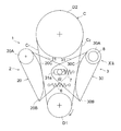
図10ないし図12は本発明の第5の実施例によるテンショニング装置を説明するための図であって、図10はテンショニング装置の模式図、図11はチェーンが伸びた状態におけるテンショニング装置の模式図、図12は図10のXII矢視一部断面図である。なお、これらの図において、前記第3、第4の実施例と同一符号は同一または相当部分を示している。
[Fifth embodiment]
10 to 12 are views for explaining a tensioning device according to a fifth embodiment of the present invention. FIG. 10 is a schematic diagram of the tensioning device, and FIG. 11 is a tensioning device in a state where the chain is extended. FIG. 12 is a partial cross-sectional view taken along arrow XII in FIG. In these drawings, the same reference numerals as those in the third and fourth embodiments denote the same or corresponding parts.
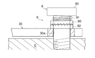
この第5の実施例は、前記第3および第4の実施例を組み合わせたものであって、付勢手段として、引張コイルばね6、7が設けられている。また、第1、第2のテンショナアーム2、3の少なくとも一方の支軸に、例えば第2のテンショナアーム3の支軸8に、図12に示すようなラチェット機構9が設けられている。
The fifth embodiment is a combination of the third and fourth embodiments, and
図12において、支軸8の下端は、エンジンE側の部品にネジ止め固定されている。支軸8は、第2のアーム部30に形成された貫通孔30aを挿通している。支軸8には、下面にラチェット歯を有する第1のラチェット部90が軸方向スライド自在かつ回転不能に取り付けられている。第1のラチェット部90は、例えば、支軸8の軸部にスプライン係合している。第1のラチェット部90は、支軸8の頭部80の下方において軸部の周りに装着された圧縮コイルばね91の弾性反発力により常時下方に付勢されている。また、第2のアーム部30の貫通孔30aの開口部には、第1のラチェット部90のラチェット歯と係合するラチェット歯を上面に有する第2のラチェット部92が固着されている。支軸8は、第2のラチェット部92を挿通している。第2のアーム部30は、第2のラチェット部92とともに、支軸8に回動自在に支持されている。
In FIG. 12, the lower end of the
これら第1、第2のラチェット部90、92等により、第2のテンショナアーム3の第2のチェーンスパンC2の側への移動を許容しつつ逆方向への移動を規制するラチェット機構が構成されている。
These first and
運転時には、付勢手段として2つの引張コイルばね6、7が設けられていることにより、付勢手段から第1、第2のテンショナアーム2、3に作用する付勢力が増し、これにより、チェーン伸びに対する各テンショナアーム2、3の応答性を向上できるとともに、チェーンスパンの共振等によるチェーンスパンのばたつきをより確実に規制できるようになる。
During operation, the two
また、この場合には、ラチェット機構を設けたことにより、運転時に第2のチェーンスパンC2から第2のテンショナアーム3に過大な押付力が作用した場合でも、第2のテンショナアーム3が第2のチェーンスパンC2から離れる側に回動するのを一層確実に規制できる。
Further, in this case, by providing the ratchet mechanism, even when an excessive pressing force from the second chain span C 2 to the
なお、第1のテンショナアーム2の側の支軸にも、同様のラチェット機構を設けるようにしてもよい。
A similar ratchet mechanism may also be provided on the support shaft on the
〔第6の実施例〕
図13は本発明の第6の実施例によるテンショニング装置の模式図である。なお、同図において、前記第3ないし第5の実施例と同一符号は同一または相当部分を示している。
[Sixth embodiment]
FIG. 13 is a schematic view of a tensioning device according to a sixth embodiment of the present invention. In the figure, the same reference numerals as those in the third to fifth embodiments denote the same or corresponding parts.
この第6の実施例は、付勢手段が捩じりコイルばねから構成されている点が、前記第3ないし第5の実施例と異なっている。すなわち、付勢手段は、第2のテンショナアーム3の支軸8の周りに配設された捩じりコイルばね15と、第1のテンショナアーム2の支軸8’の周りに配設された捩じりコイルばね16である。各捩じりコイルばね15、16の一端は支軸8、8’に係止され、他端は枢支部30A、20Aに係止されている。
The sixth embodiment is different from the third to fifth embodiments in that the biasing means is constituted by a torsion coil spring. That is, the biasing means is disposed around the
この場合には、捩じりコイルばね15、16の弾性復元力により、第1、第2のテンショナアーム2、3がそれぞれ第1、第2のチェーンスパンC1、C2に接近する側に回動する。この場合には、付勢手段が単なる捩じりコイルばねから構成されるので、付勢手段ひいては装置全体の構造を簡略化できる。
In this case, by the elastic restoring force of the torsion coil springs 15 and 16, the first, side
なお、図13に示すものでは、第1、第2のテンショナアーム2、3の双方に捩じりコイルばねが設けられた例を示したが、第2のテンショナアーム3の側の捩じりコイルばね15は省略することも可能である。
In the example shown in FIG. 13, a torsion coil spring is provided on both the first and
〔第7の実施例〕
図14は本発明の第7の実施例によるテンショニング装置の模式図である。なお、同図において、前記第1の実施例と同一符号は同一または相当部分を示している。
[Seventh embodiment]
FIG. 14 is a schematic view of a tensioning device according to a seventh embodiment of the present invention. In the figure, the same reference numerals as those in the first embodiment denote the same or corresponding parts.
前記各実施例では、第1のフランジ部21および第2のフランジ部31の連結部として、突設部およびこれが係合する長孔から構成されたものを示したが、この第7の実施例では、連結部が、第1のフランジ部21の外周の一部に形成された第1の歯部21Aと、第2のフランジ部31の外周の一部に形成され、第1の歯部21Aに噛み合う第2の歯部31Aとから構成されている。
In each of the above-described embodiments, the connecting portion between the
この場合には、テンショナ4のピストン4aが突出すると、第1のテンショナアーム2が枢支部20Aの支軸の回りを回動し、このとき、第1のフランジ部21が第1、第2の歯部21A、31Aを介して、第2のテンショナアーム3を枢支部30Aの支軸の回りに回動させる。これにより、第1、第2のテンショナアーム2、3がそれぞれチェーンスパンC1、C2の側に接近して、各チェーンスパンC1、C2の弛みが除去される。
In this case, when the
この場合には、連結部が支軸の長さ方向に突出しないので、装置全体の省スペース化に寄与できる。 In this case, since the connecting portion does not protrude in the length direction of the support shaft, it can contribute to space saving of the entire apparatus.
なお、前記各実施例では、2つのチェーンスパンを有するチェーンに本発明によるテンショニング装置が適用された例を示したが、本発明は、3つ以上のチェーンスパンを有するチェーンにおいてそのうちの2つのチェーンスパンに適用するようにしてもよい。 In each of the above-described embodiments, an example in which the tensioning device according to the present invention is applied to a chain having two chain spans is shown. However, the present invention is not limited to two of the chains having three or more chain spans. You may make it apply to a chain span.
1: テンショニング装置
2: 第1のテンショナアーム
20: 第1のアーム部
20A: 枢支端
20B: 自由端
21: 第1のフランジ部
22: 突設部(連結部)
3: 第2のテンショナアーム
30: 第2のアーム部
30A: 枢支端
30B: 自由端
31: 第2のフランジ部
31a: 長孔(連結部)
4: テンショナ(付勢手段)
C: チェーン
C1: 第1のチェーンスパン
C2: 第2のチェーンスパン
1: Tensioning device
2: 1st tensioner arm 20:
3: 2nd tensioner arm 30:
4: Tensioner (biasing means)
C: Chain C 1 : First chain span C 2 : Second chain span
Claims (9)
前記第1のチェーンスパンの外側において当該第1のチェーンスパンに沿って弧状に延設されるとともに、支軸により枢支される枢支端と自由端とを有し、チェーンが摺動する第1のアーム部と、前記第1のアーム部に一体に設けられるとともに、前記第1、第2チェーンスパン間の内部空間に向かって張り出す第1のフランジ部とを有する第1のテンショナアームと、
前記第2のチェーンスパンの外側において当該第2のチェーンスパンに沿って弧状に延設されるとともに、支軸により枢支される枢支端と自由端とを有し、チェーンが摺動する第2のアーム部と、前記第2のアーム部に一体に設けられ、前記第1、第2チェーンスパン間の前記内部空間に向かって張り出すとともに、前記第1のフランジ部とオーバラップする第2のフランジ部とを有する第2のテンショナアームと、
前記第1のテンショナアームの前記第1のフランジ部および前記第2のテンショナアームの前記第2のフランジ部とのオーバラップ部分に設けられ、前記第1、第2のフランジ部を回動自在に連結する連結部と、
前記第1のテンショナアームの前記自由端を前記第1のチェーンスパンの側に向かって付勢する付勢手段とを備え、
前記付勢手段が前記第1のテンショナアームの前記自由端を前記第1のチェーンスパンの側に向かって付勢するとき、前記連結部を介して、前記第1のテンショナアームの前記第1のフランジ部が前記第2のテンショナアームの前記第2のフランジ部を回動させて、前記第2のテンショナアームの前記第2のアーム部を前記第2のチェーンスパンの側に移動させるようになっている、
ことを特徴とするテンショニング装置。 A tensioning device for applying tension to a chain having first and second chain spans,
The first chain span extends arcuately along the first chain span, and has a pivot end and a free end pivotally supported by a pivot, and the chain slides. A first tensioner arm that is provided integrally with the first arm portion and has a first flange portion that projects toward an internal space between the first and second chain spans. ,
The second chain span extends in an arc shape along the second chain span, and has a pivot end and a free end pivotally supported by a pivot, and the chain slides. A second arm portion integrally provided on the second arm portion and projecting toward the internal space between the first and second chain spans and overlapping the first flange portion. A second tensioner arm having a plurality of flange portions;
Provided in an overlap portion between the first flange portion of the first tensioner arm and the second flange portion of the second tensioner arm, so that the first and second flange portions are rotatable. A connecting part to be connected;
Biasing means for biasing the free end of the first tensioner arm toward the first chain span;
When the biasing means biases the free end of the first tensioner arm toward the first chain span side, the first tensioner arm of the first tensioner arm is interposed via the connecting portion. The flange portion rotates the second flange portion of the second tensioner arm to move the second arm portion of the second tensioner arm toward the second chain span. ing,
A tensioning device characterized by that.
前記連結部が、
前記第2のフランジ部の前記オーバラップ部分に貫通形成された長孔と、
前記第1のフランジ部に突設されかつ前記長孔に係合するとともに、前記長孔に沿ってスライド自在な突設部と、
から構成されている、
ことを特徴とするテンショニング装置。 In claim 1,
The connecting portion is
An elongated hole formed through the overlap portion of the second flange portion;
A protruding portion that protrudes from the first flange portion and engages with the elongated hole, and is slidable along the elongated hole;
Composed of,
A tensioning device characterized by that.
前記連結部が、
前記第1のフランジ部の前記オーバラップ部分に貫通形成された第1の長孔と、
前記第2のフランジ部の前記オーバラップ部分に貫通形成され、前記第1の長孔と一部オーバラップする第2の長孔と、
当該テンショニング装置の据付側に設けられ、前記第1、第2の長孔と一部オーバラップしつつ、前記第1、第2の長孔と交差する方向に延びる第3の長孔と、
前記第3の長孔から突設しつつ前記第1ないし第3の長孔のオーバラップ部分に係止されるとともに、前記第1、第2のフランジ部の回動時に前記第1ないし第3の長孔の前記オーバラップ部分に沿ってスライド自在な突設部と、
から構成されている、
ことを特徴とするテンショニング装置。 In claim 1,
The connecting portion is
A first oblong hole formed through the overlap portion of the first flange portion;
A second elongated hole formed through the overlapped portion of the second flange portion and partially overlapping the first elongated hole;
A third elongated hole provided on the installation side of the tensioning device and extending in a direction intersecting the first and second elongated holes while partially overlapping the first and second elongated holes;
While projecting from the third elongated hole, the first to third elongated hole is locked to an overlapping portion, and the first and second flange portions are rotated when the first to third flange portions are rotated. A projecting portion that is slidable along the overlap portion of the elongated hole;
Composed of,
A tensioning device characterized by that.
前記連結部が、
前記第1、第2のフランジ部にそれぞれ形成され、互いに噛み合う第1、第2の歯部から構成されている、
ことを特徴とするテンショニング装置。 In claim 1,
The connecting portion is
The first and second flange portions are respectively formed from first and second tooth portions that mesh with each other.
A tensioning device characterized by that.
前記付勢手段が、前記第1のチェーンスパンの外側に配置され、伸退自在なピストンを有するテンショナである、
ことを特徴とするテンショニング装置。 In claim 1,
The biasing means is a tensioner that is disposed outside the first chain span and has a retractable piston.
A tensioning device characterized by that.
前記付勢手段が、前記第1のフランジ部に一端が係止されかつ前記第2のフランジ部に他端が係止された引張ばねである、
ことを特徴とするテンショニング装置。 In claim 1,
The biasing means is a tension spring having one end locked to the first flange portion and the other end locked to the second flange portion.
A tensioning device characterized by that.
前記第1または第2のテンショナアームの前記支軸には、前記第1または第2のテンショナアームの前記第1、第2のチェーンスパンの側への移動を許容しつつ逆方向への移動を規制するためのラチェット機構が設けられている、
ことを特徴とするテンショニング装置。 In claim 1,
The support shaft of the first or second tensioner arm moves in the opposite direction while allowing the first or second tensioner arm to move toward the first or second chain span. A ratchet mechanism is provided to regulate,
A tensioning device characterized by that.
前記第1または第2のテンショナアームの前記支軸には、前記第1または第2のテンショナアームの前記第1、第2のチェーンスパンの側に付勢する捩じりコイルばねが設けられている、
ことを特徴とするテンショニング装置。 In claim 1,
The support shaft of the first or second tensioner arm is provided with a torsion coil spring that urges the first or second tensioner arm toward the first or second chain span. Yes,
A tensioning device characterized by that.
前記チェーンが、エンジンの補機駆動用のチェーンまたはオイルポンプ駆動用のチェーンである、
ことを特徴とするテンショニング装置。 In claim 1,
The chain is a chain for driving an auxiliary engine of an engine or a chain for driving an oil pump.
A tensioning device characterized by that.
Priority Applications (5)
| Application Number | Priority Date | Filing Date | Title |
|---|---|---|---|
| JP2008250886A JP5469326B2 (en) | 2008-09-29 | 2008-09-29 | Tensioning device |
| US13/120,742 US8608601B2 (en) | 2008-09-29 | 2009-09-25 | Tensioning device |
| EP09816893A EP2340379B1 (en) | 2008-09-29 | 2009-09-25 | Tensioning device |
| CN200980135852.9A CN102159849B (en) | 2008-09-29 | 2009-09-25 | Tensioning device |
| PCT/US2009/058336 WO2010036868A2 (en) | 2008-09-29 | 2009-09-25 | Tensioning device |
Applications Claiming Priority (1)
| Application Number | Priority Date | Filing Date | Title |
|---|---|---|---|
| JP2008250886A JP5469326B2 (en) | 2008-09-29 | 2008-09-29 | Tensioning device |
Publications (2)
| Publication Number | Publication Date |
|---|---|
| JP2010084775A true JP2010084775A (en) | 2010-04-15 |
| JP5469326B2 JP5469326B2 (en) | 2014-04-16 |
Family
ID=42060394
Family Applications (1)
| Application Number | Title | Priority Date | Filing Date |
|---|---|---|---|
| JP2008250886A Expired - Fee Related JP5469326B2 (en) | 2008-09-29 | 2008-09-29 | Tensioning device |
Country Status (5)
| Country | Link |
|---|---|
| US (1) | US8608601B2 (en) |
| EP (1) | EP2340379B1 (en) |
| JP (1) | JP5469326B2 (en) |
| CN (1) | CN102159849B (en) |
| WO (1) | WO2010036868A2 (en) |
Cited By (2)
| Publication number | Priority date | Publication date | Assignee | Title |
|---|---|---|---|---|
| JP2017166616A (en) * | 2016-03-17 | 2017-09-21 | マツダ株式会社 | Auxiliary driving device of engine |
| KR20180113920A (en) * | 2017-04-07 | 2018-10-17 | 가부시기가이샤쯔바기모도체인 | Chain guide mechanism |
Families Citing this family (7)
| Publication number | Priority date | Publication date | Assignee | Title |
|---|---|---|---|---|
| KR20130058681A (en) * | 2010-04-15 | 2013-06-04 | 보르그워너 인코퍼레이티드 | Tensioning arrangement having a swinging arm |
| US9188202B2 (en) * | 2010-05-21 | 2015-11-17 | Borgwarner, Inc. | Tensioning mechanism for a continuous belt or chain drive system |
| DE102013218354B4 (en) * | 2013-09-13 | 2024-03-14 | Bayerische Motoren Werke Aktiengesellschaft | Tensioning device of a chain |
| CN107110020B (en) * | 2015-01-05 | 2019-11-15 | E·C·门德勒 | Variable compression ratio engine camshaft drive |
| DE102015011318A1 (en) * | 2015-08-28 | 2017-03-02 | Iwis Motorsysteme Gmbh & Co. Kg | Chain drive with combination rail |
| US10487921B2 (en) * | 2016-12-21 | 2019-11-26 | Harley-Davidson Motor Company Group, LLC | Engine with inboard cam drive tensioner |
| US11253977B2 (en) * | 2018-11-20 | 2022-02-22 | Corwin Road, L.L.C. | Turning device for decorating tumblers |
Citations (6)
| Publication number | Priority date | Publication date | Assignee | Title |
|---|---|---|---|---|
| US3869138A (en) * | 1973-04-04 | 1975-03-04 | Ford Motor Co | Steering device having a chain operated steering gear actuator |
| JPS54183570U (en) * | 1978-06-16 | 1979-12-26 | ||
| JPS6086664U (en) * | 1983-11-21 | 1985-06-14 | スズキ株式会社 | chain tensioner |
| DE4427509A1 (en) * | 1994-08-03 | 1996-02-08 | Linde Ag | Traction drive able to run in both directions of rotation |
| JP2007010142A (en) * | 2005-06-28 | 2007-01-18 | Borgwarner Inc | Tensioner |
| JP2008501912A (en) * | 2004-06-08 | 2008-01-24 | バイエリッシェ モートーレン ウエルケ アクチエンゲゼルシャフト | Traction mechanism |
Family Cites Families (42)
| Publication number | Priority date | Publication date | Assignee | Title |
|---|---|---|---|---|
| US1581624A (en) * | 1925-03-18 | 1926-04-20 | Wunderlich Paul | Synchronized regulator |
| US1758246A (en) * | 1926-06-21 | 1930-05-13 | Edward M Brackett | Belt guide |
| US2044158A (en) * | 1934-04-12 | 1936-06-16 | Westinghouse Elec Elevator Co | Chain gear |
| US2066721A (en) * | 1935-05-22 | 1937-01-05 | Jarecki Mfg Company | Belt tightening means |
| US2129107A (en) * | 1936-03-28 | 1938-09-06 | Fairbanks Morse & Co | Power transmission mechanism |
| US2156701A (en) * | 1936-11-21 | 1939-05-02 | R G Wright & Company | Belt drive mechanism |
| US2117195A (en) * | 1937-02-05 | 1938-05-10 | Kirsch Co | Venetian blind tilting mechanism |
| US3136169A (en) * | 1961-04-19 | 1964-06-09 | Reimers Getriebe Kg | Automatic chain tightening mechanism for infinitely variable cone pulley gears |
| DE1500474B2 (en) * | 1965-12-02 | 1971-10-07 | Pahtex Project Co GmbH, 4150 Kre feld | Belt drive with tensioning device |
| US3811332A (en) * | 1972-08-22 | 1974-05-21 | Fmc Corp | Automatic tensioning device |
| US3856101A (en) * | 1973-04-04 | 1974-12-24 | Ford Motor Co | Power steering device |
| GB1513722A (en) * | 1974-06-26 | 1978-06-07 | Renold Ltd | Damper apparatus for applying a tensioning force to a member |
| US4395251A (en) * | 1980-02-11 | 1983-07-26 | Borg-Warner Limited | Tensioning devices |
| US4337055A (en) * | 1980-03-10 | 1982-06-29 | Autotron Equipment Corporation | Drive belt tensioning apparatus |
| DE3326319A1 (en) * | 1983-07-21 | 1985-01-31 | Dr.Ing.H.C. F. Porsche Ag, 7000 Stuttgart | CHAIN DRIVE OF A PISTON PISTON INTERNAL COMBUSTION ENGINE |
| DE3534446A1 (en) * | 1985-09-27 | 1987-04-09 | Daimler Benz Ag | Internal combustion engine with two camshafts arranged side by side |
| DE3828350A1 (en) * | 1988-08-20 | 1990-03-01 | Skf Gmbh | AUTOMATIC CLAMPING DEVICE |
| US5246404A (en) * | 1989-04-28 | 1993-09-21 | Nhk Spring Company Limited | Unit tensioner |
| US5266066A (en) * | 1992-08-21 | 1993-11-30 | Borg-Warner Automative, Inc. | Spring blade chain tensioner |
| JPH08247236A (en) * | 1995-03-07 | 1996-09-24 | Tsubakimoto Chain Co | Chain tensioning device |
| DE19536643A1 (en) * | 1995-09-30 | 1997-04-03 | Schaeffler Waelzlager Kg | Clamping device for a control drive |
| US5797818A (en) * | 1996-04-02 | 1998-08-25 | Cloyes Gear And Products, Inc. | Chain tensioner with damping feature |
| JP3113224B2 (en) * | 1997-10-14 | 2000-11-27 | 株式会社椿本チエイン | Tensioner guide |
| DE19842723C2 (en) * | 1998-09-18 | 2000-11-02 | Porsche Ag | Chain drive for internal combustion engines |
| IT1308453B1 (en) * | 1999-04-23 | 2001-12-17 | Iveco Fiat | CHAIN TRANSMISSION DEVICE FOR THE CONTROL OF THE DISTRIBUTION OF A TWO CAMSHAFT ENDOTHERMAL ENGINE IN THE HEAD |
| JP3432197B2 (en) * | 2000-02-02 | 2003-08-04 | 株式会社椿本チエイン | Ratchet type tensioner with backlash |
| US6322469B1 (en) * | 2000-04-21 | 2001-11-27 | Borgwarner Inc. | Dual arm chain tensioner for contacting multiple chain strands |
| US6358169B1 (en) * | 2000-05-02 | 2002-03-19 | Borgwarner Inc. | Chain tensioner system having a pivoting tensioner arm |
| US6322470B1 (en) * | 2000-05-17 | 2001-11-27 | Borgwarner Inc. | Pivoting dual arm chain tensioner system for contacting multiple chain strands |
| AU2001296474A1 (en) * | 2000-10-03 | 2002-04-15 | The Gates Corporation | Accessory and motor/generator belt drive tensioner |
| US6623391B2 (en) * | 2000-10-17 | 2003-09-23 | Cloyes Gear And Products, Inc. | Blade-type mechanical chain tensioner with external strengthening rib |
| US6955621B2 (en) * | 2001-04-26 | 2005-10-18 | Borgwarner Inc. | Rotary actuating hydraulic tensioner |
| US6942589B2 (en) * | 2002-02-08 | 2005-09-13 | Dayco Products, Llc | Offset starter generator drive utilizing a fixed-offset dual-arm pivoted tensioner |
| ITMI20021243A1 (en) * | 2002-06-07 | 2003-12-09 | Regina Ind Spa | FLUID TENSIONER FOR CHAIN |
| US6849015B2 (en) * | 2003-01-31 | 2005-02-01 | Borgwarner Inc. | Ratcheting pivot arm tensioner with backlash |
| US7097579B2 (en) * | 2003-10-15 | 2006-08-29 | Borgwarner Inc. | Pivoting chain guide and tensioner assembly |
| KR100524255B1 (en) * | 2003-12-23 | 2005-11-01 | 조문행 | Compound planetary gear set and gear train having the same |
| US20060270502A1 (en) * | 2005-05-27 | 2006-11-30 | Borgwarner Inc. | Tensioner for simultaneously tensioning multiple strands |
| US7455606B2 (en) * | 2005-06-08 | 2008-11-25 | Borgwarner Inc. | Mechanical chain tensioner with a rotational ratcheting device |
| US7476168B2 (en) * | 2005-08-15 | 2009-01-13 | Borgwarner Inc. | Pivoting mechanical tensioner with cross strand damping |
| US7628719B2 (en) * | 2005-10-26 | 2009-12-08 | Borgwarner, Inc. | Mechanical strap tensioner for multi-strand tensioning |
| EP2008001B1 (en) * | 2006-04-20 | 2012-10-17 | BorgWarner Inc. | Ratchet mechanism for a chain drive |
-
2008
- 2008-09-29 JP JP2008250886A patent/JP5469326B2/en not_active Expired - Fee Related
-
2009
- 2009-09-25 EP EP09816893A patent/EP2340379B1/en not_active Not-in-force
- 2009-09-25 CN CN200980135852.9A patent/CN102159849B/en not_active Expired - Fee Related
- 2009-09-25 WO PCT/US2009/058336 patent/WO2010036868A2/en active Application Filing
- 2009-09-25 US US13/120,742 patent/US8608601B2/en active Active
Patent Citations (6)
| Publication number | Priority date | Publication date | Assignee | Title |
|---|---|---|---|---|
| US3869138A (en) * | 1973-04-04 | 1975-03-04 | Ford Motor Co | Steering device having a chain operated steering gear actuator |
| JPS54183570U (en) * | 1978-06-16 | 1979-12-26 | ||
| JPS6086664U (en) * | 1983-11-21 | 1985-06-14 | スズキ株式会社 | chain tensioner |
| DE4427509A1 (en) * | 1994-08-03 | 1996-02-08 | Linde Ag | Traction drive able to run in both directions of rotation |
| JP2008501912A (en) * | 2004-06-08 | 2008-01-24 | バイエリッシェ モートーレン ウエルケ アクチエンゲゼルシャフト | Traction mechanism |
| JP2007010142A (en) * | 2005-06-28 | 2007-01-18 | Borgwarner Inc | Tensioner |
Cited By (6)
| Publication number | Priority date | Publication date | Assignee | Title |
|---|---|---|---|---|
| JP2017166616A (en) * | 2016-03-17 | 2017-09-21 | マツダ株式会社 | Auxiliary driving device of engine |
| WO2017159577A1 (en) * | 2016-03-17 | 2017-09-21 | マツダ株式会社 | Accessory drive device for engine |
| US10865857B2 (en) | 2016-03-17 | 2020-12-15 | Mazda Motor Corporation | Accessory drive device for engine |
| KR20180113920A (en) * | 2017-04-07 | 2018-10-17 | 가부시기가이샤쯔바기모도체인 | Chain guide mechanism |
| KR102135861B1 (en) * | 2017-04-07 | 2020-07-20 | 가부시기가이샤쯔바기모도체인 | Chain guide mechanism |
| US10738862B2 (en) | 2017-04-07 | 2020-08-11 | Tsubakimoto Chain Co. | Chain guide mechanism |
Also Published As
| Publication number | Publication date |
|---|---|
| CN102159849A (en) | 2011-08-17 |
| US20110201465A1 (en) | 2011-08-18 |
| CN102159849B (en) | 2014-06-18 |
| US8608601B2 (en) | 2013-12-17 |
| WO2010036868A3 (en) | 2010-07-08 |
| JP5469326B2 (en) | 2014-04-16 |
| EP2340379A2 (en) | 2011-07-06 |
| EP2340379A4 (en) | 2012-03-21 |
| WO2010036868A2 (en) | 2010-04-01 |
| EP2340379B1 (en) | 2012-11-07 |
Similar Documents
| Publication | Publication Date | Title |
|---|---|---|
| JP5469326B2 (en) | Tensioning device | |
| JP5127712B2 (en) | Chain guide and tensioner assembly | |
| JP4807906B2 (en) | Double arm chain tensioner system | |
| JP5625064B2 (en) | Multi-strand tension adjusting device having moving arm | |
| JP4619072B2 (en) | Pivot chain guide / tensioner arm assembly | |
| JP2006329418A (en) | Tensioner device | |
| JP4046684B2 (en) | Engine tensioner | |
| JP2004232859A (en) | Tensioning system | |
| JP4128196B2 (en) | Ratchet tensioner | |
| JP5244808B2 (en) | Pivoting arm tensioner with sliding ratchet mechanism | |
| US20130023367A1 (en) | Tensioning arrangement having a swinging arm | |
| JP2009275911A (en) | Chain tensioner device | |
| JP5618738B2 (en) | Chain tensioner device | |
| JP5424446B2 (en) | Tensioning device | |
| JP3193272U (en) | Starter chain guide device | |
| JP4777660B2 (en) | Blade tensioner device | |
| JP4275609B2 (en) | Chain tensioner | |
| JP4954320B2 (en) | Chain tensioner device | |
| KR100534702B1 (en) | Chain drive system of v-type engine | |
| RU181429U1 (en) | STRETCHING DEVICE | |
| JP2009250384A (en) | Chain tensioner | |
| CN101634353B (en) | There is the chain drive tensioner system of translating pivot point | |
| JP2009299727A (en) | Chain transmission movable lever | |
| JP2010001913A (en) | Movable lever for chain transmission | |
| JPS6317887Y2 (en) |
Legal Events
| Date | Code | Title | Description |
|---|---|---|---|
| A621 | Written request for application examination |
Free format text: JAPANESE INTERMEDIATE CODE: A621 Effective date: 20110722 |
|
| A521 | Request for written amendment filed |
Free format text: JAPANESE INTERMEDIATE CODE: A523 Effective date: 20120603 |
|
| A977 | Report on retrieval |
Free format text: JAPANESE INTERMEDIATE CODE: A971007 Effective date: 20130220 |
|
| A131 | Notification of reasons for refusal |
Free format text: JAPANESE INTERMEDIATE CODE: A131 Effective date: 20130225 |
|
| A521 | Request for written amendment filed |
Free format text: JAPANESE INTERMEDIATE CODE: A523 Effective date: 20130329 |
|
| A131 | Notification of reasons for refusal |
Free format text: JAPANESE INTERMEDIATE CODE: A131 Effective date: 20130805 |
|
| A521 | Request for written amendment filed |
Free format text: JAPANESE INTERMEDIATE CODE: A523 Effective date: 20130831 |
|
| TRDD | Decision of grant or rejection written | ||
| A01 | Written decision to grant a patent or to grant a registration (utility model) |
Free format text: JAPANESE INTERMEDIATE CODE: A01 Effective date: 20140127 |
|
| A61 | First payment of annual fees (during grant procedure) |
Free format text: JAPANESE INTERMEDIATE CODE: A61 Effective date: 20140131 |
|
| R150 | Certificate of patent or registration of utility model |
Ref document number: 5469326 Country of ref document: JP Free format text: JAPANESE INTERMEDIATE CODE: R150 Free format text: JAPANESE INTERMEDIATE CODE: R150 |
|
| R250 | Receipt of annual fees |
Free format text: JAPANESE INTERMEDIATE CODE: R250 |
|
| R250 | Receipt of annual fees |
Free format text: JAPANESE INTERMEDIATE CODE: R250 |
|
| R250 | Receipt of annual fees |
Free format text: JAPANESE INTERMEDIATE CODE: R250 |
|
| R250 | Receipt of annual fees |
Free format text: JAPANESE INTERMEDIATE CODE: R250 |
|
| R250 | Receipt of annual fees |
Free format text: JAPANESE INTERMEDIATE CODE: R250 |
|
| LAPS | Cancellation because of no payment of annual fees |