JP2010084313A - Taping structure and garment - Google Patents
Taping structure and garment Download PDFInfo
- Publication number
- JP2010084313A JP2010084313A JP2009205391A JP2009205391A JP2010084313A JP 2010084313 A JP2010084313 A JP 2010084313A JP 2009205391 A JP2009205391 A JP 2009205391A JP 2009205391 A JP2009205391 A JP 2009205391A JP 2010084313 A JP2010084313 A JP 2010084313A
- Authority
- JP
- Japan
- Prior art keywords
- band
- intermittent
- anchor
- taping
- joint
- Prior art date
- Legal status (The legal status is an assumption and is not a legal conclusion. Google has not performed a legal analysis and makes no representation as to the accuracy of the status listed.)
- Granted
Links
- 241000309551 Arthraxon hispidus Species 0.000 claims description 30
- 239000004744 fabric Substances 0.000 claims description 26
- 238000006243 chemical reaction Methods 0.000 claims description 4
- 238000009958 sewing Methods 0.000 claims description 3
- 230000000694 effects Effects 0.000 abstract description 22
- 230000033001 locomotion Effects 0.000 description 17
- 210000000689 upper leg Anatomy 0.000 description 7
- 230000008602 contraction Effects 0.000 description 6
- 210000001699 lower leg Anatomy 0.000 description 6
- 238000004519 manufacturing process Methods 0.000 description 6
- 210000003423 ankle Anatomy 0.000 description 5
- 238000010586 diagram Methods 0.000 description 5
- 238000004873 anchoring Methods 0.000 description 4
- 238000005452 bending Methods 0.000 description 4
- 239000000463 material Substances 0.000 description 4
- 210000002683 foot Anatomy 0.000 description 3
- 210000001503 joint Anatomy 0.000 description 3
- 230000002093 peripheral effect Effects 0.000 description 3
- 239000000853 adhesive Substances 0.000 description 2
- 230000001070 adhesive effect Effects 0.000 description 2
- 230000005540 biological transmission Effects 0.000 description 2
- 238000006073 displacement reaction Methods 0.000 description 2
- 210000001624 hip Anatomy 0.000 description 2
- 210000004394 hip joint Anatomy 0.000 description 2
- 210000003127 knee Anatomy 0.000 description 2
- 210000003205 muscle Anatomy 0.000 description 2
- 230000004118 muscle contraction Effects 0.000 description 2
- 210000004417 patella Anatomy 0.000 description 2
- 230000000644 propagated effect Effects 0.000 description 2
- 210000000323 shoulder joint Anatomy 0.000 description 2
- 238000004804 winding Methods 0.000 description 2
- 206010049565 Muscle fatigue Diseases 0.000 description 1
- 208000005392 Spasm Diseases 0.000 description 1
- 239000002390 adhesive tape Substances 0.000 description 1
- 230000003872 anastomosis Effects 0.000 description 1
- 210000000544 articulatio talocruralis Anatomy 0.000 description 1
- 230000000386 athletic effect Effects 0.000 description 1
- 210000001217 buttock Anatomy 0.000 description 1
- 239000000470 constituent Substances 0.000 description 1
- 230000002542 deteriorative effect Effects 0.000 description 1
- 229910003460 diamond Inorganic materials 0.000 description 1
- 239000010432 diamond Substances 0.000 description 1
- 230000005489 elastic deformation Effects 0.000 description 1
- 210000001513 elbow Anatomy 0.000 description 1
- 238000005516 engineering process Methods 0.000 description 1
- 230000036541 health Effects 0.000 description 1
- 238000009434 installation Methods 0.000 description 1
- 210000002414 leg Anatomy 0.000 description 1
- 230000014759 maintenance of location Effects 0.000 description 1
- 230000007257 malfunction Effects 0.000 description 1
- 230000004899 motility Effects 0.000 description 1
- 230000002265 prevention Effects 0.000 description 1
- 230000009467 reduction Effects 0.000 description 1
- 230000004044 response Effects 0.000 description 1
- 238000004904 shortening Methods 0.000 description 1
- 230000003068 static effect Effects 0.000 description 1
- 210000000707 wrist Anatomy 0.000 description 1
Images


Landscapes
- Professional, Industrial, Or Sporting Protective Garments (AREA)
Abstract
Description
本発明は、人体の関節部を含む部分を覆うように装着することで、人体の所定関節内部の運動力学的支点を中心とした範囲にテーピング効果を発揮するテーピング構造体、及びこれを備えた被服に関する。 The present invention is provided with a taping structure that exhibits a taping effect in a range centered on a kinematic fulcrum inside a predetermined joint of a human body by wearing so as to cover a portion including a joint portion of the human body, and the same. Regarding clothing.
従来、テーピング機能を保持させてサポートし得るロングガードル等下半身用被覆に関し、テーピングし得る幅員の所定の外側帯状片と内側帯状片を被覆本体の構成部材よりも緊締力に富む強い伸縮特性を保持させたものが開示される。これは外側帯状片の内縁が、ウエスト部の臀部外側から大腿部外側、下方の前大腿部を通って膝蓋部を避けて裾部外側へ至るものであり、また外側帯状片の外縁が、内縁に沿った緩い弯曲曲線状としており、また内側帯状片の外縁は大腿部内側の縦中心線を形成し、膝蓋部を除く大腿部とか退部の全身側を包み込むものとされる(例えば、特許文献1参照)。この構成により、所定範囲を空窓部分的に除いた全周域に内側帯状片と外側帯状片が充当され、テーピング装置と同等の体表面の締め付けを行なうことで筋肉疲労の軽減効果や障害の予防と治療に供するものとされる。 Conventionally, with regard to the lower body covering such as a long girdle that can be supported by holding the taping function, the predetermined outer and inner strips of the width that can be taped have stronger elastic properties than the components of the cover body. Is disclosed. This is because the inner edge of the outer band-shaped piece extends from the outer side of the buttocks of the waist part to the outer side of the thigh, the lower front thigh, and the outer side of the hem part by avoiding the patella. The outer band of the inner band-shaped piece forms a longitudinal center line on the inner side of the thigh and wraps around the whole body side of the thigh and the retraction part except for the patella. (For example, refer to Patent Document 1). With this configuration, the inner strip and outer strip are allotted to the entire circumference excluding the predetermined area of the empty window, and by tightening the body surface equivalent to the taping device, the effect of reducing muscle fatigue and Provided for prevention and treatment.
しかしながら、上記従来のテーピング構造を取り入れたウエアは、テーピング理論を中核にはしていても、テーピングにおける大前提である、皮膚面へのアンカー機能に欠ける。すなわちアンカー固定といわれる皮膚面への貼り付け固定がないままテーピングを行なっても、テーピングテープが皮膚面を滑ってしまい、テーピング効果は低下或いは無効化してしまう。特に、大きな力が加わったときほど身体の保護、外力の分散が最も必要となるのに拘わらず、このときほど皮膚面を大きく滑るものとなってしまう。 However, the wear incorporating the above-described conventional taping structure lacks the anchoring function to the skin surface, which is a major premise in taping, even if the taping theory is the core. That is, even if taping is performed without fixing to the skin surface, which is called anchor fixation, the taping tape slides on the skin surface, and the taping effect is reduced or invalidated. In particular, the greater the applied force, the more the body needs to be protected and the external force distributed, but the more the skin surface slips.
たとえば上記ウエアはテーピング構造が内蔵されているとしても、皮膚面をテーピング構造が滑るという事実に対応したものではなく、固定力の低下や、筋肉の過度な収縮或いは過度な緊張(スパズム等)に対応したものではない。具体的にいえば、端部の滑りあがり減少を防止する役目や、テーピング構造間の連接の役目は、すべてウエアの限界強度に依存しており、これらテーピング構造の役目を引き出すためにはウエアの張力強度を高めるしかない。ところが、テーピング構造の効果を引き出すべくウエアの張力強度を上げていくと、今度は着用上の不具合が生じてくる。さらにテーピング構造の張力強度と同程度までウエアの張力強度を上げてしまうと、テーピング構造の意味自体がなくなってしまう。 For example, even if the above-mentioned wear has a built-in taping structure, it does not correspond to the fact that the taping structure slides on the skin surface, but it is caused by a decrease in fixing force, excessive muscle contraction or excessive tension (such as spasm). It is not compatible. More specifically, the role of preventing the reduction of the sliding up of the end and the role of connection between the taping structures all depend on the limit strength of the wear, and in order to draw out the role of these taping structures, There is no choice but to increase the tensile strength. However, if the tensile strength of the wear is increased in order to bring out the effect of the taping structure, a problem in wearing occurs. Furthermore, if the tensile strength of the wear is increased to the same level as that of the taping structure, the meaning of the taping structure itself is lost.
一方、サポータも皮膚に固定するものではないため、滑りが発生する。サポータ効果を得るためにサポータの弾性係数を下げていくと可動域の制限、運動能力の低下、着用時間の短縮という問題が発声する傾向にある。逆に弾性係数を増加させていくとすべりが増大してサポータの固定性、復元性といったサポータ効果が低下するので、関節や筋肉の保護に支障を期待してしまう可能性がある。サポータの皮膚面との摩擦力がアンカー機能の代用として考えられていても、大きな摩擦力が働けば動きが制限され、着用時の運動性が低下してしまう。逆に摩擦力を小さくすると固定性や復元力が低下してしまう。 On the other hand, since the supporter is not fixed to the skin, slipping occurs. If the elastic modulus of the supporter is lowered in order to obtain a supporter effect, problems such as limitation of range of motion, lowering of exercise ability, and shortening of wearing time tend to occur. On the contrary, if the elastic modulus is increased, the slip increases and the supporter effects such as the supporter's fixation and restoration properties are lowered, so that there is a possibility that the protection of joints and muscles may be expected to be hindered. Even if the frictional force with the skin surface of the supporter is considered as a substitute for the anchor function, if a large frictional force is applied, the movement is restricted, and the motility during wearing is reduced. Conversely, if the frictional force is reduced, the fixing property and the restoring force are reduced.
またそもそもサポータはテーピングとは異なり、サポート部分全体を広範囲に締め付けて固定するものであるから、余分な範囲の固定によって動きが制限されたり、運動時の疲労感が増大するものである。つまりサポータは独立性を有した構造ではあるものの、サポータ効果の効率と着用者の疲労性は反比例する。 In the first place, the supporter is different from taping in that the entire support portion is fastened and fixed over a wide range, so that the movement is restricted by an extra range of fixation, and the feeling of fatigue during exercise increases. That is, although the supporter has an independent structure, the efficiency of the supporter effect and the wearer's fatigue are inversely proportional.
またウエアとサポータとを単純に組み合わせたものについても、ウエア、サポータの各効果は根本的に不特定な広範囲性を持つものなので、単純にサポータやウエアの構造内部にテーピング構造を形成しても矛盾や不具合が発生する。 In addition, even for a simple combination of wear and supporter, each effect of wear and supporter has a fundamentally unspecified range, so even if a taping structure is simply formed inside the structure of the supporter or wearer Inconsistencies and malfunctions occur.
そこで本発明は、皮膚面への貼り付けを行なわずに、皮膚面へのアンカー機能を発揮し、テーピング効果を果たすことができるテーピング構造体、及びこれを備えた被服を提供することを課題とする。 Therefore, the present invention has an object to provide a taping structure that can exert a taping effect by exerting an anchoring function to the skin surface without being attached to the skin surface, and a clothing provided with the taping structure. To do.
上記課題を解決すべく本発明では以下(1)〜(4)の手段を講じている。 In order to solve the above problems, the present invention takes the following means (1) to (4).
(1)本発明のテーピング構造体は、人体の所定関節内部の運動力学的支点を中心とした範囲に周着しうる筒状布からなるテーピング構造体であって、
・装着時の関節頭Hに略中央当接するように位置し、中央の関節頭Hから複数の連接帯3へ放射状に連なることで、この放射方向にのみ伸縮するサポート帯1と、
・周着範囲の両端にて人体の一部に通して装着するためのアンカー開口20を有して人体に緊止する両端一対のアンカー帯2と、
・筒外周の周着方向に沿って一定パターンの間隔ごとに並ぶ間欠孔4群によって両端一対のアンカー帯2間に複数列形成される間欠孔列とを有してなる。
そして各間欠孔列は、隣り合う各間欠孔列に対して間欠孔4の周着方向の位相がずれて配置されることを特徴とする。
(1) A taping structure of the present invention is a taping structure made of a cylindrical cloth that can be worn around a kinematic fulcrum inside a predetermined joint of a human body,
A
A pair of
A plurality of intermittent hole rows formed between a pair of
And each intermittent hole row | line | column is arrange | positioned with respect to each adjacent intermittent hole row | line | column, and the phase of the surrounding direction of the
複数列の間欠孔列を、隣り合う列で位相が異なるように設けることで、各列の間欠孔4同士が、列設方向(アンカー帯2間を亘る筒長方向)に対して真っ直ぐではなく、斜め方向にずれて並ぶ。筒長方向は装着時にほぼ人体の骨格軸に沿う方向となるため、間欠孔4間の構造布が、骨格軸に対して交差する傾斜方向への伸縮性を有することとなる。よって骨格軸に沿う縦方向への伸縮力はすべて傾斜方向へ変換され、関節の運動によってもサポート布1がずれにくいものとなる。
By providing a plurality of rows of intermittent holes so that the phases are different in adjacent rows, the
上記のものであれば、関節内部の動的中心となる運動力学的支点に外力が還元される。そして関節における噛み合わせのアライアントを確保し、関節の破損や痛みを抑える。また動的中心点がずれずに守られることで、関節周辺の健や筋肉の動きをサポートすることができる。 If it is said thing, an external force will be reduced to the kinematic fulcrum used as the dynamic center inside a joint. And secure the alliance of the joint in the joint, and suppress the damage and pain of the joint. Moreover, by protecting the dynamic center point without shifting, it is possible to support the health and muscle movement around the joint.
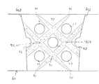
具体的にはたとえば、真円形または楕円形の間欠孔44が関節からの伸張軸方向に対して斜め方向に配列される。すなわち、サポート帯1の上下各列にて両側面部分に一対ずつ配置された真円形または楕円形の間欠孔44は、サポート帯1と重なる列にて位相が90度ずらされることで、伸張軸方向に対して斜め方向にずれて前後面部分に一対の間欠孔4が配置される。なお真円形または楕円形は、装着時の筒状布の伸張によって不均一に変形した扁平円形となる。この扁平円形は、主に周方向へ広がるように変形し、横長扁平楕円となる。
Specifically, for example, the perfect circular or elliptical
間欠孔4を有することで、応力が曲縁上を伝わって間欠孔4間の連接帯3全体に分散されながら伝わる。これにより大きな応力集中が発生せず、偏りの少ない弾性が得られる。弾性変形により扁平形状となりにくく、元の形状を保持することでサポート帯1によるサポート位置及びアンカー帯2による固定位置が大きくずれることがない。
(2)前記アンカー帯2は、
着用することで人体の所定関節にテーピング効果を与えるものであり、
前記所定関節の関節頭Hを覆い、それぞれが関節頭Hを中心とした複数の放射方向に伸縮性を有してサポートする一又は複数のサポート帯1と、
前記アンカー開口20それぞれにて人体に環状に周着するアンカー帯2(先端帯及び基端帯)と、
サポート帯1同士またはサポート帯1とアンカー帯2(21,22)を繋ぐ複数の連接帯3とから構成されてなり、
列設方向に対して連接帯3は、前記間欠孔4の間に設けられ、サポート帯1を前記放射方向に沿って引っ張ることを特徴とする。
By having the
(2) The
It gives a taping effect to a predetermined joint of the human body by wearing it,
One or a plurality of
Anchor bands 2 (tip band and proximal band) that are annularly attached to the human body at each of the
It is composed of
The connecting
このようなものであれば、関節の動きによってサポート帯1に加えられた力は各連接帯3に分散され、また連接帯3にかかる伸縮力は、両端のアンカー帯2の巻き付け方向に変換される。このため、サポート帯1に大きな外力が加えられるほど、その外力は連接帯3に伝わり、関節頭Hへ放射状に大きな伸縮反力を与えると共に、その外力によって連接帯3の位置のずれが防止されることとなる。このため、テーピング構造体の構成材の張力は非加圧の静的状態、所定限度の被加圧の動的状態のいずれにおいても、それ自体で力学的につりあっており、他の固定部分に依存しない力の平衡性による形状保持性を有している。
If this is the case, the force applied to the
関節頭Hを中心とした放射状の張力が発生するようにし、かつその張力が両端のアンカー帯2の巻きつけ力に変換されるようにすることで、テーピング構造体を皮膚に貼り付けなくても、位置ずれを生じることなく関節部分を効率的にサポートすることができる。
(3) サポート帯1は、関節軸対称の2本の交差線による四方向に伸縮性を有すると共に、連接帯3が前記四方向に沿ってアンカー帯2の巻着方向に伸縮可能に連なることが好ましい。
By causing radial tension around the joint head H to be generated and converting the tension into the wrapping force of the
(3) The
サポート帯1はたとえば湾曲縁からなる方形形状をしており、方形の対角線である四方向に伸縮性を有するものとなっている。上下方向に均等に力が分散され、その分散力は両端それぞれのアンカー帯2に均等に伝播するため、関節部を中心としてより力の釣り合いが均等に保たれる。
(4)本発明の被服は、前記いずれか記載のテーピング構造体が、着衣によって人体表面に沿う被服布に縫着されてなることを特徴とする。
The
(4) The clothing of the present invention is characterized in that the taping structure according to any one of the above is sewn to a clothing cloth along a human body surface by clothing.
サポート帯1が、関節軸対称の2本の交差線による三方向または四方向に伸縮性を有すると共に、連接帯3が前記三方向または四方向に沿ってアンカー帯2の巻着方向に伸縮可能に連なる。
The
サポート帯1はたとえば湾曲縁からなる方形形状をしており、方形の対角線である四方向に伸縮性を有するものとなっている。上下方向に均等に力が分散され、その分散力は両端それぞれのアンカー帯2に均等に伝播するため、関節部を中心としてより力の釣り合いが均等に保たれる。
変形量が大きいほどアンカー帯2の内応力が増し、周着端部を強く緊止してアンカー機能を発揮する。従来の粘着テープによるアンカー固定と異なり、人体に貼り付け固定していないにも拘わらず、テーピング構造体は関節の動きが大きくなるほど、よりずれにくいものとなる。
The
As the amount of deformation increases, the internal stress of the
上記構成のものであれば、関節頭Hに当接したサポート帯1が連接帯3に四方放射状に支持されたまま、全体としてアンカー帯2で人体にアンカー固定されることとなる。これにより、皮膚面への貼り付けを行なわずに、皮膚面へのアンカー機能を発揮し、テーピング効果を果たすことができるテーピング構造体、及びこれを備えた被服を提供することが可能となった。
If it is the thing of the said structure, the support belt | band |
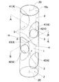
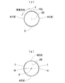
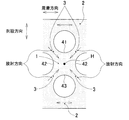
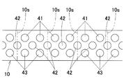
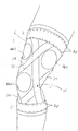
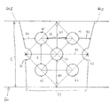
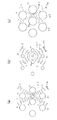
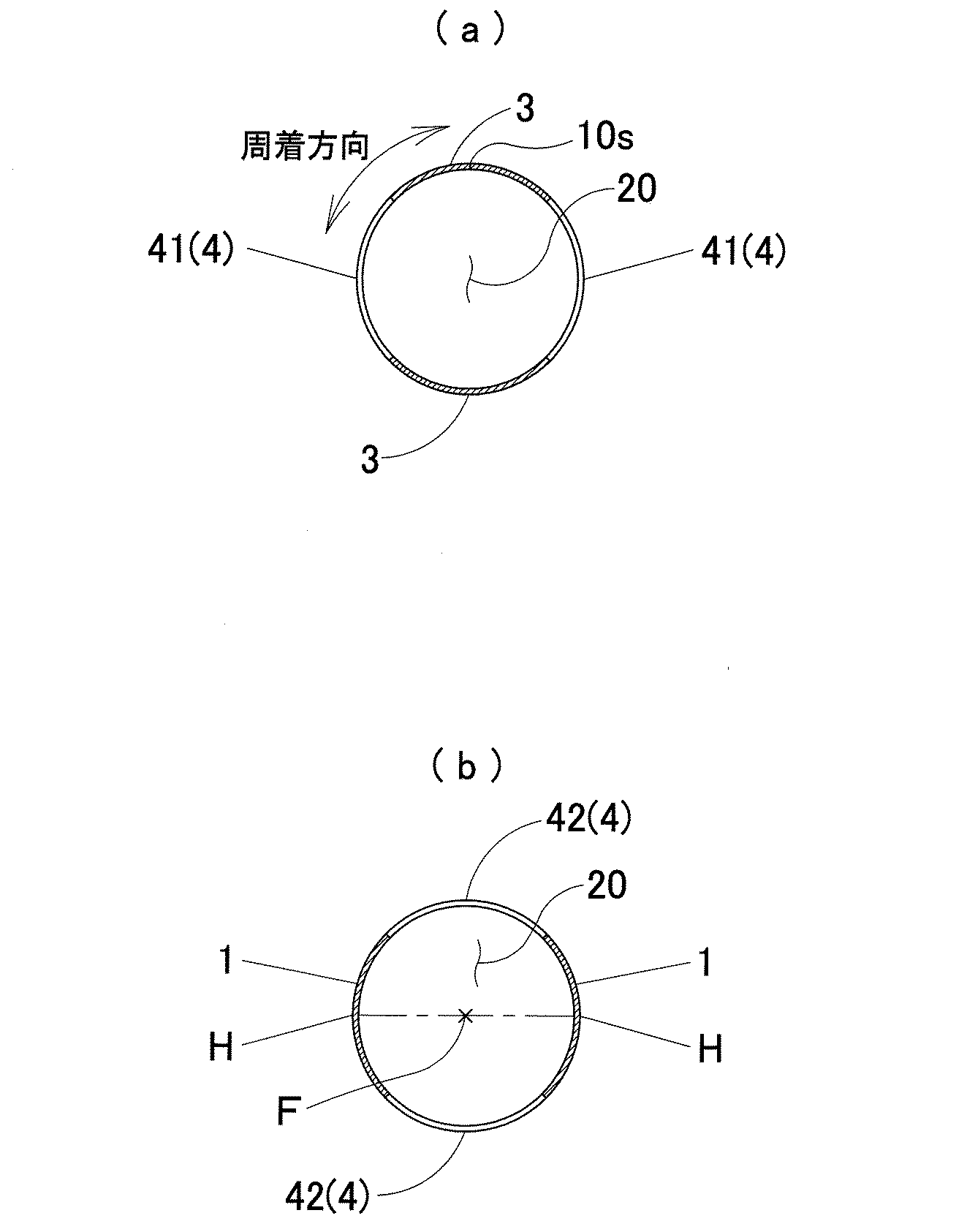
本発明の実施の形態について図面を参照して詳細に説明する。図1ないし図4は本発明の実施例1のテーピング構造体について、それぞれ斜視説明図、平面視A−A線およびB−B線断面図、関節頭H周辺の側面視部分拡大図、および連続製造工程における展開図を示す。図5ないし図8は本発明の実施例2のテーピング構造体について、それぞれ斜視説明図、平面視C−C線およびD−D線断面図、関節頭H周辺の側面視部分拡大図、および連続製造工程における展開図を示す。図9及び図10は本発明の実施例3、図11及び図12は本発明の実施例4、並びに図13及び図14は本発明の実施例5のテーピング構造体であり、各組それぞれ正面及び背面視説明図を示す。そして図15は、実施例4、5のテーピング構造体を備えた本発明の実施例6の被服の正面視説明図を示す。 Embodiments of the present invention will be described in detail with reference to the drawings. 1 to 4 are respectively a perspective explanatory view, a sectional view taken along a line AA and a line BB, a partially enlarged view of a side view around the joint head H, and a continuous view of the taping structure according to the first embodiment of the present invention. The development view in a manufacturing process is shown. 5 to 8 are a perspective explanatory view, a cross-sectional view taken along the line CC and a line DD, a partially enlarged view around the joint head H, and a continuous view, respectively, of the taping structure according to the second embodiment of the present invention. The development view in a manufacturing process is shown. 9 and 10 show a third embodiment of the present invention, FIGS. 11 and 12 show a fourth embodiment of the present invention, and FIGS. 13 and 14 show a taping structure of the fifth embodiment of the present invention. And the back view explanatory drawing is shown. And FIG. 15: shows front view explanatory drawing of the clothing of Example 6 of this invention provided with the taping structure of Examples 4 and 5. FIG.
また図16は各実施例における間欠孔4の孔周縁の縫合例の説明図を示す。図17、図18、図19はそれぞれ本発明の実施例7、実施例8、実施例9のテーピング構造体の使用状態を示し、図20及び図21は、このうち実施例7のテーピング構造体の連続製造工程における展開図を示す。
Moreover, FIG. 16 shows explanatory drawing of the example of stitching | suture of the hole periphery of the
図22は展開図配置において、間欠孔の大きさの相違による装着時張力を比較して表した概念図であり、図23は同じく展開図配置における、間欠孔間の距離の相違による間欠孔の大きさの好ましい配置例を示す。また図24は実施例1のサポータ構造体で間欠孔の数を変えたときの装着時張力の方向の違いを比較する概念図である。そして図25、図26はそれぞれ本発明の実施例10、実施例11のテーピング構造体の使用状態を示す。 FIG. 22 is a conceptual diagram comparing the tension at the time of mounting due to the difference in the size of the intermittent holes in the developed view arrangement, and FIG. 23 is the same as that of the intermittent holes due to the difference in the distance between the intermittent holes in the developed view arrangement. A preferred arrangement example of the size is shown. FIG. 24 is a conceptual diagram for comparing the difference in the direction of tension at the time of mounting when the number of intermittent holes is changed in the supporter structure of the first embodiment. 25 and 26 show the usage state of the taping structures according to the tenth and eleventh embodiments of the present invention, respectively.
<本発明のテーピング構造体の全体構成>
本発明のテーピング構造体は基本的に、人体の一又は複数の所定関節部に通すためのアンカー開口20を両端に有した一本の筒状体(実施例1,2,及び実施例7〜11)または複数の筒状体の組み合わせ(実施例3〜6)からなる。この筒状体は下記基本構成からなり、装着によって前記所定関節の動的中心部を中心とした範囲に一体的に周着しうる。
・隣り合う間欠孔列間(第一間欠孔列41と第二間欠孔列42間、第二間欠孔列42と第三間欠孔列43間、・・・)に位置して複数の連接帯3を放射状に連ねるものであり、装着時にその中央位置において対象となる関節の関節頭Hに当接するサポート帯1
・周着締止によって人体皮膚表面へのアンカー機能を発揮するアンカー帯2
・間欠孔4間に位置してアンカー帯2とサポート帯1の間を相互に連接する連接帯3
・両端のアンカー開口20間をわたる列設方向へ複数列設けられ、それぞれ筒外周の周着方向に沿って並ぶ複数個の間欠孔4からなる間欠孔列(第一間欠孔列41、第二間欠孔列42、第三間欠孔列43、・・・)
そして本発明のテーピング構造体の全ての実施例において各間欠孔列(41,42,43,・・・)は、隣り合う各間欠孔列に対して間欠孔4の周着方向の位相がずれて配置される。これにより連接帯3は、前記列設方向に対して傾斜した方向にのみ伸縮し、この連接帯3の伸縮による張力が内応力としてアンカー帯2に伝わり、アンカー帯2の周着による人体への緊止力が強まる。
<Overall structure of taping structure of the present invention>
The taping structure of the present invention basically includes a single cylindrical body (Examples 1 and 2 and Examples 7 to 7) having
A plurality of connecting bands located between adjacent intermittent hole rows (between the first
・
A connecting
A plurality of intermittent hole rows (first
And in all the embodiments of the taping structure of the present invention, the intermittent hole rows (41, 42, 43,...) Are out of phase with the
本発明では、アンカー帯2がその周着機能の増加によってアンカー機能を果たし、ずり上がりやすべりが無いものとなっている。また引っ張りの内応力は最終的にアンカー帯2の周着方向に変換され、かつ変換時にアンカー体に対して直交する方向の力がかからないようにし、力学的につりあった状態となっている。
In the present invention, the
(力学的な動的中心点の保護)
すなわち本発明では、関節内部にある力学的な動的中心点が力の発生上の中心点であるとし、この中心点の両端にある関節頭Hを、一対のテーピング帯1でそれぞれ両側から囲い、それぞれのテーピング帯1を四方から連接帯3で放射連接し、上下端でアンカー帯2によって人体に固定するものとしている。内部から力が伝わったとき、テーピング帯1から周囲の連接帯3へ張力が発生する。この張力は、本来は人体構造の体表上を直線的に伝わろうとするものであるが、本発明ではアンカー帯2と直行する列設方向への伸縮を発生させずに、張力が対表上を斜めに回り込みながら周方向の裏側まで伝達するものとしている。これは、各間欠孔列が隣り合う間欠孔列に対して間欠孔4の周着方向の位相がずれて配置され、連接帯3が列設方向(縦方向)に真っ直ぐ連なる部分を有していないことに基づく。
(Mechanical dynamic center point protection)
That is, in the present invention, the dynamic dynamic center point inside the joint is the center point for generating force, and the joint heads H at both ends of the center point are surrounded by the pair of taping
体表上を回りこんだ張力は、関節周囲を部分的に亘る連接帯3の伸長方向の内圧に変換され、この内圧は、身体方向や関節方向の中心部に向けて圧力(身体内圧)を加えるように働きかける。この身体内圧は、関節やその構成体のかみ合わせや吻合といったアライメントを守るように働き、動的な中心を支点として力を発生させている。これにより運動能力を低下させること無く適切なテーピング効果を発揮させることができる。
The tension that wraps around the body surface is converted into an internal pressure in the extension direction of the
これにより関節の動的中心点を中心とした圧力をかけ続けることができ、関節が動かされて変形した場合でもテーピング構造自体で力学的な独立性を保っている。変形による力学的な独立性を保つことで、例えば被服に固定された場合でも被服本体の張力強度に依存せず、常にテーピング効果を発揮することができる。 As a result, it is possible to continue to apply pressure around the dynamic center point of the joint, and even when the joint is moved and deformed, the taping structure itself maintains mechanical independence. By maintaining the mechanical independence due to the deformation, for example, even when fixed to the clothes, the taping effect can always be exhibited without depending on the tensile strength of the clothes body.
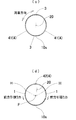
また足首関節などのように、関節頭Hが突出した構造に使用する場合には、静止状態でもテーピング帯1から周囲の連接帯3へ放射方向の張力がある程度かかるものとなっている。このような場合、関節が動いたときにより多く伸縮し、動きによって生じる張力が増すと共に、動きに対応して圧力(身体内圧)が即時にかかるものとなる。
Further, when used in a structure in which the joint head H protrudes, such as an ankle joint, radial tension is applied from the
(アンカー帯2による緊止)
連接体への内圧は最終的に、テーピング構造体の両端にあるアンカー帯2の周着方向への内圧に変換される。これにより皮膚への貼り付けをしなくてもずれることなく、テーピングにおけるアンカー効果を発揮することができる。
(Tightening with anchor band 2)
The internal pressure to the connecting body is finally converted into an internal pressure in the circumferential direction of the
(高張力ラインによる伸縮特性)
本発明の実施例9(図19)、実施例11(図26)のサポータ構造体は、サポータ布60とアンカー帯2、帯体30とが重ねられて別素材として部分的に縫合固定されてなる。具体的には実施例9,11においては、複数の帯体30が、両端部の環状のアンカー帯2上の等間隔位置からそれぞれ連接体3として斜めに伸長し、この帯体30(連接体3)同士が各伸長方向の交差点でサポート帯1として交差する。これら複数の帯体30は図19や図26に示すようなクロスライン状或いはネット状に菱形配走し、両端のアンカー帯2に縫合固定される。さらにこれらアンカー帯2及び帯体30の裏側(装着時の内側)全体を覆うように、複数の間欠孔4が間欠形成されたサポータ布60が配置される。サポータ布60は上下端部がアンカー開口となって、装着個所に応じた筒状に形成される。また、各アンカー開口に沿ってアンカー帯2が配されると共に、アンカー帯2の帯幅両側部に沿ってサポータ布60とアンカー帯2とが縫合固定される。筒状にループ形成されたサポータ布60の表面に複数の帯体30が重なり、重なった各帯体30間の中心位置には図16に示す円形の間欠孔641,642,643が配される。帯体30はそれぞれ菱形のクロスライン状に斜めに菱形交差配列しており、各菱形の中心位置と重なる部分が間欠孔4の中心位置となっている。複数の帯体30の交差部がサポート帯1として関節頭Hを中心とした放射状の張力構造となると共に、全体が筒状にループ形成された複合的な張力構造となっている。
(Extension / contraction characteristics by high tension line)
In the supporter structures of the ninth embodiment (FIG. 19) and the eleventh embodiment (FIG. 26) of the present invention, the
上記実施例9,11はサポータ布60上にアンカー帯2、帯体30といった張力構造部が別部材として重なって構成されるが、このような構成に限らず実施例8(図18)のように下部アンカー帯2のみが固定部2Sにて縫合固定されたものでもよい。なお、実施例1乃至7、及び実施例10は上記アンカー帯2、帯体30やサポート帯1を、一枚の伸縮布内に内包して一体的に形成されたものであると考えることができる。
In the ninth and eleventh embodiments, the tension structure portions such as the
(間欠孔4)
全ての実施例において、間欠孔4は、周縁が直線部を有さず曲線のみから構成され、間欠孔4が変形しにくい非伸縮性の糸による縫合孔として構成される。例えば図15に示すように、伸縮量の小さい被服布5で間欠孔4の孔縁に沿って縫合固定することにより、或いは、例えば図16に示すような孔縁の周囲を囲う二重円状の第一縫合部4S1、及び第一縫合部4S1と孔縁の間をジグザグ状に連続縫合した第二縫合部4S2で縫合することにより、孔縁自体すなわち孔の周長が伸縮しにくいように構成される。
(Intermittent hole 4)
In all of the embodiments, the
装着者の関節の動きによって、帯体30やサポータ布60や連接体3には伸長方向に沿って張力が発生するが、この張力は、方向が変換されたうえで間欠孔4の周囲に沿って左右両側方へ回り込み、さらに筒状体からなる構造全体の裏側へ回りこむというバイパス効果を伴う(図24の(c)参照)。このバイパス効果は、関節運動によって発生した負荷張力が、間欠孔4の円形縁に沿って回り込んでその周囲を優先的に伝わって行き、左右に分かれて体表面上を回り込みながら指向的に伝わっていくことで、結果的に、張力発生部に対して有意な力を還元することとなる。
Due to the movement of the wearer's joints, tension is generated in the
また間欠孔4の孔縁部を、直線部分を有さない曲線のみで構成し、かつ非伸縮性として縫合したことにより、間欠孔4の内部に張力が存在せず、間欠孔4を除く残りの部分全体に比較的高い張力がループ状に伝わる。さらに、隣り合う間欠孔4同士が近接する部分により大きい力が加わり、周囲よりもさらに張力の高い高張力点が発生する。ここで複数の間欠孔4は、それぞれの中心部が縦向きの菱形状となるように菱形配列されているため、前記高張力点をつないだ高張力ラインが、図21や図22、図24に示すようにクロスライン状或いはネット状に配列形成される。なお図21では端部の高張力点70の張力が比較的小さく、これよりも第一、第三間欠孔列41,43の列上にある端列上高張力点71が大きく、これらよりも第二間欠孔列42の列状にある中央列上高張力点72が最も大きいものとなっており、この中央列上高張力点72が間接頭Hと共通するサポート帯1の中心となっている。
In addition, since the hole edge portion of the
この図21,22あるいは図24に示すような張力密度の相違に基づく高張力ラインは、非伸縮性の間欠孔4の配列によってもたらされるものであり、ゴム等のサポーター構造体の構成材の伸縮性以外の第二の伸縮特性といえる。本発明のテーピング構造体は、本来図24(a)や(b)のように平面部を直線的に伝わろうとする張力の伝達経路(高張力ライン)を、曲線縁のみからなる円形の間欠孔4の孔縁を非伸縮構成とし、適切なダイヤ状配列とすることによってコントロールし、指向性を持たせて有益な力として還元するものとしている。これにより、身体表面の構造体は、より高い制動性と、力学的中心点(サポート帯1部分)の復元力を獲得している。
The high tension line based on the difference in tension density as shown in FIGS. 21, 22 or 24 is provided by the arrangement of the non-stretchable
(一般的なテーピング、サポータとの比較)
ここで、テーピングとサポータとでは、部分覆設と全面覆設という覆設範囲、並びに皮膚への貼り付けの有無において異なる。本来のテーピングは、対象関節を中心として緊張させたテーピング帯でその周囲の必要部分のみを被い、両端のアンカー部でテーピング帯を皮膚に粘着固定するものである。テーピングは必要な部分のみを特定的に固定することで動的な力学上の関節の中心点を保護し、必要な内圧の向きや強度を調節できるものである。しかしテーピングの仕方によってその効果が変わり、テーピング施術者の力量にゆだねられてしまう。
(Comparison with general taping and supporter)
Here, the taping and the supporter differ in the covering range of partial covering and full covering, and the presence or absence of application to the skin. The original taping is a taped band that is tensioned around the target joint and covers only the necessary parts around it, and the taping band is adhesively fixed to the skin with anchors at both ends. Taping protects the center point of the dynamic mechanical joint by specifically fixing only the necessary part, and can adjust the direction and strength of the required internal pressure. However, the effect changes depending on the way of taping, and it depends on the ability of the taping practitioner.
一方、サポータは対象関節をその周囲まで全面的に覆って動きを制限する一体型の覆設体である。皮膚へ貼り付け固定せず、覆設したサポータ布全体で関節周囲を単に広範囲に締め付けることで動きを抑制するものである。このため、装着が容易であり技術や経験に効果を左右されることが無い代わりに、力学上の動的中心点や、保護に必要な内圧の向きや強度を調節することができない。 On the other hand, the supporter is an integrated covering body that covers the entire surface of the target joint to limit the movement thereof. The movement is restrained by simply tightening the periphery of the joint over a wide range with the entire supporter cloth that is not attached and fixed to the skin. For this reason, the dynamic center point of dynamics and the direction and strength of the internal pressure necessary for protection cannot be adjusted, instead of being easily mounted and not being affected by technology and experience.
本発明ではこれらテーピングとサポータの両者の利便性や効果を両備すべく、粘着部等による皮膚への固定手段を有さずに、関節の必要部分のみを覆う一体型構造体のテーピング構造体としている。 In the present invention, in order to provide both convenience and effect of both the taping and the supporter, as a taping structure of an integrated structure that covers only a necessary part of the joint without having a fixing means to the skin by an adhesive portion or the like. Yes.
(間欠孔4の孔径と伸長率の関係)
間欠孔4の孔径と伸長率の関係としては以下が好ましい。
(1)装着時に同じ列の間欠孔4の中心を横切る横断面上の伸長率をXとし、素材の横方向の解放時伸長率S1を150%、横方向の装着時伸長率S2を120%とする。横断面周囲長さに対して、間欠孔4の孔径4Dが40%であれば、必要な伸長率Xは下記数式1より110%となる。
(Relationship between hole diameter and elongation rate of intermittent hole 4)
The relationship between the hole diameter of the
(1) The elongation rate on the cross section that crosses the center of the
(2)横断面周囲の長さに対する間欠孔4Dの限界伸長率をL(%)とすると、一列内に2つ並んだ間欠孔4の中心を横断する方向において、下記数式2が成立する。
(2) When the limit elongation rate of the intermittent hole 4D with respect to the length of the perimeter of the cross section is L (%), the following
横断面周囲の長さに対して2つの間欠孔4Dが占める長さは40%なので、20(%)を40(%)で除した50%と100%との和150%が、横断面伸縮率の最大限界値Zとなる。Zの値が低いほど張力比率の高い構造となる。
Since the length of the two intermittent holes 4D with respect to the length of the circumference of the cross section is 40%, the sum of 50% obtained by dividing 20 (%) by 40 (%) and 100% is 150%. It becomes the maximum limit value Z of the rate. The lower the value of Z, the higher the tension ratio.
(孔径と中心間隔の関係)
計算された張力の伝達経路や加圧角度の指向性をクロスライン状或いはネット状に確保するためには、間欠孔の数や大きさは自ずと規定され、図22に示すような縦型正方形配列が最も理想的な配列となる。ただし力学的中心点までの距離は数や大きさに伴って変化する。図25に示すように、孔間距離が大きければ張力は拡散的になるため、間欠孔4の大きさ(孔径4D)は比例して大きくなるべきであり、逆に孔間距離が小さければ孔径4Dはそれに比例して小さくなるべきである。
(Relationship between hole diameter and center distance)
In order to ensure the calculated tension transmission path and pressure angle directivity in a cross-line or net shape, the number and size of the intermittent holes are naturally defined, and a vertical square array as shown in FIG. Is the most ideal arrangement. However, the distance to the mechanical center varies with the number and size. As shown in FIG. 25, since the tension becomes diffusive when the inter-hole distance is large, the size of the intermittent hole 4 (hole diameter 4D) should be increased proportionally. Conversely, if the inter-hole distance is small, the hole diameter 4D should be reduced proportionally.
以下、各構成につき実施例に基づいて詳述する。 Hereinafter, each configuration will be described in detail based on examples.
本発明の実施例1のテーピング構造体は、粘着剤などの人体への貼り付け手段を有することなく、単に着用することで人体の所定関節にテーピング効果を与える一体的な筒状布からなる。この筒状布は略等径であり、肘、膝、手首、足首といった2軸を繋ぐ屈曲関節を囲うようにして、両端に設けたアンカー開口20を人体に通して装着する。これにより、前記屈曲関節内部の運動力学的支点を中心としたテーピング効果を発揮しうる。
The taping structure of Example 1 of the present invention is made of an integral tubular cloth that has a taper effect on a predetermined joint of the human body simply by wearing without having a means for attaching the adhesive to the human body. This cylindrical cloth is substantially equal in diameter, and is fitted with
(サポート帯1)
実施例1のサポート帯1は、所定関節の関節頭Hを覆い、それぞれが関節頭Hを中心とした複数の放射方向に伸縮性を有してサポートする。筒状体において間欠孔列間に位置して複数の連接帯3と放射状に連なる。また装着時に関節頭Hに中央当接し、この関節頭Hを中心とした前記連接帯3と連なる放射方向に沿って伸縮する。図1ではHが三列目の列中心の高さ。すなわち三列目の間欠孔4の縦方向(列設方向)中央にきている。Fは左右のHの中点となっている。また実施例1のサポート帯1は一対の関節頭Hに対して一対だけ設けられるが、他、実施例3、4、5のようにサポートする間接頭Hの数に応じて複数個が設けられるものとしてもよい。
(Support zone 1)
The
(アンカー帯2)
アンカー帯2は、先端側及び基端側にそれぞれ設けられ、前記アンカー開口20それぞれにて人体に環状に周着する。実施例3,4,5のように複数の筒体が組み合された形状においても開口部端として概念される。
(Anchor belt 2)
The
(連接帯3)
連接帯3はサポート帯1同士またはサポート帯1とアンカー帯2(21,22)を繋ぐ複数のテーピング幅の伸縮布片からなる。連接帯3は左右のサポート帯1(11,12)並びに先端側及び基端側のアンカー帯2(21,22)同士を連接するものであり、関節軸に対して斜め方向に伸びる。本発明のテーピング構造体は複数の連接帯3に連接されて一体的に構成される。
(Connecting zone 3)
The connecting
連接帯3はまた、間欠孔4間に位置し、間欠孔列の列設方向および筒外周の周着方向に対して傾斜した方向にのみ伸縮する。また連接帯3には円形孔が設けられることで、一のアンカー帯2から他のアンカー帯2までを直線的に繋ぐ部分が存在しない。
The connecting
(複数列の間欠孔列)
実施例1の間欠孔列は第一間欠孔列41、第二間欠孔列42、第三間欠孔列43の3列からなり、筒長方向を列設方向として順に列設される。これら間欠孔列は、前記アンカー開口20同士を亘る列設方向に沿って順に並ぶ。ここで、各間欠孔列である第一間欠孔列41、第二間欠孔列42、第三間欠孔列43は、隣り合う各間欠孔列に対して間欠孔4の周着方向の位相がずれて配置される。これにより、同列内で間欠孔4間に位置する筒状体の一部分が前記列設方向に対して傾斜した方向にのみ伸縮する。また、各列における間欠孔4はいずれも、装着時に前記所定関節の関節頭Hを除く位置に当接する。
(間欠孔列)
間欠孔列は、前記アンカー開口20同士を亘る列設方向に沿って順に並ぶ。
(Multiple rows of intermittent holes)
The intermittent hole row of Example 1 is composed of three rows of a first
(Intermittent hole array)
The intermittent hole rows are arranged in order along the row direction across the
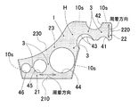
実施例2のテーピング構造体は、図5に示すように、第二間欠孔列42を一つ、第一及び第三間欠孔列41、43を二つずつとして、肘、膝などの大きく曲がる屈曲関節の屈曲挟部を覆うものとしている。人体の一関節を中心とした一方から他方へわたることで間接の所定方向への動きを制限して関節をサポートする。
水平放射方向
関節頭Hが後方寄りに位置する
前方引張り力
力学中心Fが
As shown in FIG. 5, the taping structure of the second embodiment bends greatly such as an elbow and a knee with one second
The front tensile mechanical center F where the horizontal radial joint head H is located at the rear is
実施例3のテーピング構造体は、図9、10に示すように、人体の一方の肩関節の動的中心点を被い、一方のアンカー口である肩口側上腕から他方のアンカー口である胸部へ亘ることで間接の所定方向への動きを制限して関節をサポートする。
前記関節の一方及び他方側の人体部分に環状に巻きつくアンカー帯2と、関節の動軸中心上の両端に配置され、アンカー帯2に向かってそれぞれ三方向に放射状に伸びるサポート帯1と、サポート帯1と一および他のアンカー帯2とをそれぞれ連接する連接帯3とから一体的に構成される。
(実施例4ないし6)
実施例4のテーピング構造体は、図11、12に示すように、人体の両肩関節を含む上半身の動的中心点を被い、一方のアンカー口である両肩口側上腕から他方のアンカー口である胸部へ亘ることで間接の所定方向への動きを制限して関節をサポートするものである。
As shown in FIGS. 9 and 10, the taping structure of Example 3 covers the dynamic center point of one shoulder joint of a human body, and the chest that is the other anchor mouth from the shoulder-arm upper arm that is one anchor mouth. The joint is supported by restricting movement in a predetermined direction indirectly.
An
(Examples 4 to 6)
As shown in FIGS. 11 and 12, the taping structure of Example 4 covers the dynamic center point of the upper body including both shoulder joints of the human body, and the other anchor port from the upper arm on both shoulders side, which is one anchor port. The joint is supported by restricting indirect movement in a predetermined direction by extending to the chest.
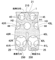
実施例5のテーピング構造体は、図13、14に示すように、人体のまた股関節、腰関節を含む下半身の動的中心点を被い、一方のアンカー口である腰部から他方のアンカー口である両肩口大腿部へ亘ることで間接の所定方向への動きを制限して関節をサポートするものである。 As shown in FIGS. 13 and 14, the taping structure of Example 5 covers the dynamic center point of the lower body including the hip joint and the hip joint of the human body, and from the waist portion which is one anchor port to the other anchor port. The joint is supported by restricting indirect movement in a predetermined direction by extending to both shoulders and thighs.
実施例6は被服本体上半身部に実施例4のテーピング構造体が縫着されるとともに被服本体下半身部に実施例5のテーピング構造体が縫着されることで、実施例4、5のテーピング構造体を含んで全身を覆うように構成された被服である。間欠孔4部内を伸縮布で覆うことで水着として使用することもできる。
(他の実施例)
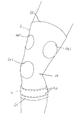
上述の実施例のほか、他の実施例(実施例10、11)として、前下腿部から足背部にわたって同一型紙から直線的に縫製し、非装着状態から足の甲を足先側に倒した形状の足収容部を有する靴下としてもよい(図25,26)。この靴下の両側面においては、関節頭Hである足のくるぶし部分を中心とした、足首側、かかと側及び下腿側を三辺とする三辺領域を固定しうる軸固定布が縫合固定されている。この場合、下腿部を環状に締め付ける下腿のアンカー帯2と、アンカー帯2のうち下腿部の両側面それぞれからサポート帯1の中心を亘る連接布3(帯体31,32,33,34)とが縫合固定される。連接布3(帯体31,32,33,34)は所定長さを保ちうる弾性体からなり、菱形状に配列されることで、サポート帯1を列設方向に対して斜めに引っ張る。
In the sixth embodiment, the taping structure of the fourth embodiment is sewn to the upper half of the clothing main body, and the taping structure of the fifth embodiment is sewn to the lower half of the clothing main body, so that the taping structure of the fourth and fifth embodiments is sewn. It is a garment configured to cover the entire body including the body. It can also be used as a swimsuit by covering the inside of the
(Other examples)
In addition to the above-described embodiments, as other embodiments (Examples 10 and 11), sewing is performed linearly from the same pattern from the front lower leg to the back of the foot, and the instep is turned to the toe side from the non-wearing state. It is good also as a sock which has the leg accommodating part of the shape which carried out (FIGS. 25 and 26). On both sides of the sock, a shaft fixing cloth capable of fixing three sides of the ankle side, the heel side, and the crus side around the ankle portion of the foot, which is the joint head H, is stitched and fixed. Yes. In this case, an
また両側面のサポート帯1は、それぞれ装着時において、三辺方向に沿って収縮する内応力と、三辺の各位置から中心方向に向かって収縮する内応力とを有した収縮体からなると共に、両側面間で繋がる対応辺同士が引き合う方向に収縮する内応力を有する。
Each of the
そして両側面のサポート帯1間のうち、足首側辺と下腿側辺間である前頂部において、足首前部ないし足背部をサポート帯1の内応力よりも強い伸縮力で覆う強伸縮材が、サポート帯1の前記前頂部の裏面同士を繋ぐように設けられ、
各サポート帯1の前記前頂部の先側が頂方向に伸張した伸張部を有すると共に、両側面の伸張部間を連接帯3が交差して亘る。
And, between the
The front side of the front top part of each
F 運動力学的支点
H 関節頭
H1 中央関節頭
H2 右関節頭
H3 左関節頭
1 サポート帯
10 原型布
10s 縫合線
2 アンカー帯
20 アンカー開口
21 胸囲帯
210 胸囲開口
22 腕囲帯
220 腕囲開口
23 片たすき帯
230 片たすき開口
24 首回帯
240 首回開口
25 腿囲帯
250 腿囲開口
3 連接帯
4 間欠孔
41L,R 第一間欠孔列
42L,R 第二間欠孔列
43L,R 第三間欠孔列
44 第四間欠孔列
45 第五間欠孔列
46 第六間欠孔列
47 第七間欠孔列
48 第八間欠孔列
49 第九間欠孔列
410L,R 第十間欠孔列
411L,R 第十一間欠孔列
5 被服布
F kinematic fulcrum H joint head H1 central joint head H2 right joint head H3 left
Claims (4)
装着時の関節頭Hに略中央当接するように位置し、中央の関節頭Hから複数の連接帯3へ放射状に連なることで、この放射方向に伸縮するサポート帯1と、
周着範囲の両端にて人体の一部に通して装着するためのアンカー開口20を有して人体に緊止する両端一対のアンカー帯2と、
筒外周の周着方向に沿って一定パターンの間隔ごとに並ぶ間欠孔4群によって両端一対のアンカー帯2間に複数列形成される間欠孔列とを有してなり、
各間欠孔列は、隣り合う各間欠孔列に対して間欠孔4の周着方向の位相がずれて配置されることを特徴とするテーピング構造体。 A taping structure made of a cylindrical cloth that can be put around a kinematic fulcrum inside a predetermined joint of a human body,
A support band 1 that is positioned so as to substantially abut against the joint head H at the time of wearing, and that radially extends from the central joint head H to the plurality of connection bands 3;
A pair of anchor bands 2 at both ends having an anchor opening 20 for attaching to a part of the human body at both ends of the circumferential wearing range and fastened to the human body;
A plurality of intermittent hole rows formed between a pair of anchor bands 2 at both ends by a group of intermittent holes arranged at regular pattern intervals along the circumferential direction of the outer circumference of the cylinder,
Each intermittent hole row is arranged such that the phase in the circumferential direction of the intermittent hole 4 is shifted with respect to each adjacent intermittent hole row.
連接帯3は、前記間欠孔4の間に設けられた中央部細幅のつづら状のものであると共に、サポート帯1を前記放射方向に沿って引っ張ることで、サポート帯1の中心方向に弾性反力による放射中心点への内応力を生じさせる請求項1記載のテーピング構造体。 The intermittent hole 4 has a substantially circular shape with an inner curve,
The articulated band 3 is formed in a narrow-shaped pierced central portion provided between the intermittent holes 4 and is elastic in the center direction of the support band 1 by pulling the support band 1 along the radial direction. The taping structure according to claim 1, wherein an internal stress is generated on the radial center point by a reaction force.
連接帯3が関節頭H方向に引っ張られたときの弾性反力によって、アンカー帯2の周着方向に沿って内応力が生じ、これによってアンカー帯の人体関節への緊止力が増加する請求項1または2記載のテーピング構造体。 The end of the connecting band 3 intersects with the anchor band 2 at a predetermined angle of intersection,
The elastic reaction force when the connecting band 3 is pulled in the joint head H direction causes an internal stress along the circumferential direction of the anchor band 2, thereby increasing the fastening force of the anchor band to the human joint. Item 3. A taping structure according to item 1 or 2.
A clothing obtained by sewing the taping structure according to any one of claims 1, 2, and 3 on a clothing cloth along a human body surface by clothing.
Priority Applications (1)
| Application Number | Priority Date | Filing Date | Title |
|---|---|---|---|
| JP2009205391A JP5483540B2 (en) | 2008-09-06 | 2009-09-06 | Taping structure and clothing |
Applications Claiming Priority (3)
| Application Number | Priority Date | Filing Date | Title |
|---|---|---|---|
| JP2008229165 | 2008-09-06 | ||
| JP2008229165 | 2008-09-06 | ||
| JP2009205391A JP5483540B2 (en) | 2008-09-06 | 2009-09-06 | Taping structure and clothing |
Publications (2)
| Publication Number | Publication Date |
|---|---|
| JP2010084313A true JP2010084313A (en) | 2010-04-15 |
| JP5483540B2 JP5483540B2 (en) | 2014-05-07 |
Family
ID=42248554
Family Applications (1)
| Application Number | Title | Priority Date | Filing Date |
|---|---|---|---|
| JP2009205391A Expired - Fee Related JP5483540B2 (en) | 2008-09-06 | 2009-09-06 | Taping structure and clothing |
Country Status (1)
| Country | Link |
|---|---|
| JP (1) | JP5483540B2 (en) |
Cited By (2)
| Publication number | Priority date | Publication date | Assignee | Title |
|---|---|---|---|---|
| JP2016223026A (en) * | 2015-05-29 | 2016-12-28 | 有限会社蘇生会 | Taping unit |
| KR102234561B1 (en) * | 2020-08-26 | 2021-03-31 | 주식회사 피플파이 | Leg taping patch |
Citations (7)
| Publication number | Priority date | Publication date | Assignee | Title |
|---|---|---|---|---|
| JPH02185246A (en) * | 1988-12-28 | 1990-07-19 | Raman Max | Supporting appliance for orthopedic and making material thereof |
| JPH0480577U (en) * | 1990-11-22 | 1992-07-14 | ||
| JPH0641641B2 (en) * | 1990-06-21 | 1994-06-01 | 株式会社ワコール | Clothing for lower body such as long girdle with taping function |
| JP2003052727A (en) * | 2001-08-08 | 2003-02-25 | Shinsei:Kk | Knee supporter |
| JP3122760U (en) * | 2006-04-13 | 2006-06-29 | 敬一郎 山下 | Thermal insulation supporter |
| WO2007018484A1 (en) * | 2005-07-20 | 2007-02-15 | Wellgate Products, Llc | Orthopedic devices with compressive elastomer formed directly onto a base material |
| JP3129871U (en) * | 2006-12-18 | 2007-03-08 | 敏郎 一井 | Taping sheet |
-
2009
- 2009-09-06 JP JP2009205391A patent/JP5483540B2/en not_active Expired - Fee Related
Patent Citations (7)
| Publication number | Priority date | Publication date | Assignee | Title |
|---|---|---|---|---|
| JPH02185246A (en) * | 1988-12-28 | 1990-07-19 | Raman Max | Supporting appliance for orthopedic and making material thereof |
| JPH0641641B2 (en) * | 1990-06-21 | 1994-06-01 | 株式会社ワコール | Clothing for lower body such as long girdle with taping function |
| JPH0480577U (en) * | 1990-11-22 | 1992-07-14 | ||
| JP2003052727A (en) * | 2001-08-08 | 2003-02-25 | Shinsei:Kk | Knee supporter |
| WO2007018484A1 (en) * | 2005-07-20 | 2007-02-15 | Wellgate Products, Llc | Orthopedic devices with compressive elastomer formed directly onto a base material |
| JP3122760U (en) * | 2006-04-13 | 2006-06-29 | 敬一郎 山下 | Thermal insulation supporter |
| JP3129871U (en) * | 2006-12-18 | 2007-03-08 | 敏郎 一井 | Taping sheet |
Cited By (2)
| Publication number | Priority date | Publication date | Assignee | Title |
|---|---|---|---|---|
| JP2016223026A (en) * | 2015-05-29 | 2016-12-28 | 有限会社蘇生会 | Taping unit |
| KR102234561B1 (en) * | 2020-08-26 | 2021-03-31 | 주식회사 피플파이 | Leg taping patch |
Also Published As
| Publication number | Publication date |
|---|---|
| JP5483540B2 (en) | 2014-05-07 |
Similar Documents
| Publication | Publication Date | Title |
|---|---|---|
| EP2526792B1 (en) | Elbow joint supporter | |
| US7780614B2 (en) | Orthopedic supports and method of using same | |
| US7615023B2 (en) | Donning support with framework fastened to garment | |
| US20060026732A1 (en) | Support with framework fastened to garment | |
| US20060026733A1 (en) | Shirt, pants and jumpsuit having expandable framework | |
| US20060070165A1 (en) | Donning potentiating support with expandable framework fastened to garment | |
| JP2009000277A (en) | Knee supporter whose shift is prevented | |
| JP6603651B2 (en) | Knee supporter and knee joint support method | |
| JP7437391B2 (en) | Ankle brace devices, systems, and methods | |
| KR101766644B1 (en) | Support Clothes for Muscle Strengthening | |
| JP6534321B2 (en) | Knee support | |
| JP5483540B2 (en) | Taping structure and clothing | |
| JP6357490B2 (en) | Knee orthosis | |
| JP5223144B2 (en) | Ankle orthosis | |
| JP5961370B2 (en) | Supporter | |
| JP6751665B2 (en) | Knee wear | |
| JP3208786U (en) | Knee supporter | |
| JP5967693B2 (en) | Knee supporter | |
| JP2009114577A (en) | Foot joint supporter | |
| WO2020037011A1 (en) | Garment | |
| JP2006218058A (en) | Supporter and supporter belt | |
| JP2007239160A (en) | Dance clothing | |
| JP2014198159A (en) | Ankle fitting tool, method for fitting ankle fitting tool, and stretchable belt for fixing ankle | |
| JP2019058485A (en) | Knee brace | |
| JP3219046U (en) | Knee supporter |
Legal Events
| Date | Code | Title | Description |
|---|---|---|---|
| A621 | Written request for application examination |
Free format text: JAPANESE INTERMEDIATE CODE: A621 Effective date: 20120626 |
|
| RD04 | Notification of resignation of power of attorney |
Free format text: JAPANESE INTERMEDIATE CODE: A7424 Effective date: 20121218 |
|
| RD02 | Notification of acceptance of power of attorney |
Free format text: JAPANESE INTERMEDIATE CODE: A7422 Effective date: 20121226 |
|
| A977 | Report on retrieval |
Free format text: JAPANESE INTERMEDIATE CODE: A971007 Effective date: 20130606 |
|
| A131 | Notification of reasons for refusal |
Free format text: JAPANESE INTERMEDIATE CODE: A131 Effective date: 20130627 |
|
| A521 | Request for written amendment filed |
Free format text: JAPANESE INTERMEDIATE CODE: A523 Effective date: 20130826 |
|
| TRDD | Decision of grant or rejection written | ||
| A01 | Written decision to grant a patent or to grant a registration (utility model) |
Free format text: JAPANESE INTERMEDIATE CODE: A01 Effective date: 20140212 |
|
| A61 | First payment of annual fees (during grant procedure) |
Free format text: JAPANESE INTERMEDIATE CODE: A61 Effective date: 20140214 |
|
| R150 | Certificate of patent or registration of utility model |
Ref document number: 5483540 Country of ref document: JP Free format text: JAPANESE INTERMEDIATE CODE: R150 |
|
| R250 | Receipt of annual fees |
Free format text: JAPANESE INTERMEDIATE CODE: R250 |
|
| LAPS | Cancellation because of no payment of annual fees |