JP2010082806A - Special signature to produce moving picture, and booklet including the same - Google Patents
Special signature to produce moving picture, and booklet including the same Download PDFInfo
- Publication number
- JP2010082806A JP2010082806A JP2008250896A JP2008250896A JP2010082806A JP 2010082806 A JP2010082806 A JP 2010082806A JP 2008250896 A JP2008250896 A JP 2008250896A JP 2008250896 A JP2008250896 A JP 2008250896A JP 2010082806 A JP2010082806 A JP 2010082806A
- Authority
- JP
- Japan
- Prior art keywords
- section
- cover
- booklet
- signature
- film gauge
- Prior art date
- Legal status (The legal status is an assumption and is not a legal conclusion. Google has not performed a legal analysis and makes no representation as to the accuracy of the status listed.)
- Granted
Links
Images


Abstract
Description
本発明は、背糊および脇糊で表紙に固定されて冊子を構成する特殊折丁に関する。本発明の特殊折丁は、複合画像で構成される下絵の上で、フィルムゲージをスライド移動させることで、絵が動いているかの如き視覚的効果を与える。
さらに本発明は、この特殊折丁を含めて製本された冊子に関する。この冊子は、例えば、雑誌、カタログ、パンフレット、書籍として使用することができる。
The present invention relates to a special signature that constitutes a booklet that is fixed to a cover with back glue and side glue. The special signature of the present invention gives a visual effect as if the picture is moving by sliding the film gauge on the sketch composed of the composite image.
Furthermore, the present invention relates to a booklet that is bound to include this special signature. This booklet can be used, for example, as a magazine, catalog, brochure, or book.
「下絵」と「フィルムゲージ」を利用して、パラパラ漫画とよく似た原理で、あたかも絵が動いているかのような視覚的効果を与える技術は、従来から知られている(例えば、特許文献1、2)。その原理を簡単に説明すると、次の通りである。 A technique that gives a visual effect as if a picture is moving on the basis of a principle similar to that of a flip book by using “understory” and “film gauge” has been conventionally known (for example, patent literature). 1, 2). The principle will be briefly described as follows.
≪画素が2つの場合:図1、図2≫
図1は、「複合画像で構成される下絵」の作成原理を示している。ここでは、複合画像は、2つの画素から構成される。まず、画素1、2をそれぞれ等間隔“α”で間引いて、「残像」と「欠け」が繰り返す中間画素を作成する。次に、中間画像1の「欠け」部分に、中間画像2の「残像」部分が一致するようにして、両者を組み合わせて複合画像を作成する。
<< When there are two pixels: FIGS. 1 and 2 >>
FIG. 1 shows the principle of creating a “background picture composed of composite images”. Here, the composite image is composed of two pixels. First, the pixels 1 and 2 are thinned out at equal intervals “α” to create intermediate pixels in which “afterimage” and “missing” repeat. Next, the “afterimage” portion of the intermediate image 2 matches the “missing” portion of the intermediate image 1, and a composite image is created by combining the two.
一方、図2に示したフィルムゲージは、透明の基材上に「黒塗りの細長い帯状領域」を等間隔で印刷したものであって、「帯状領域の幅」と「各帯状領域間の間隔」とが等しい(共に“α”)。
このフィルムゲージを複合画像上に重ね合わせて、両者を相対的にスライドさせると、図2に示したように、中間画素1の「残像」がフィルムゲージ上の各帯状領域間の透明領域にきたときに星形模様が視認される(A)。
一方、中間画素2の「残像」がフィルムゲージ上の各帯状領域間の透明領域にきたときに丸形模様が視認される(B)。
On the other hand, the film gauge shown in FIG. 2 is obtained by printing “black elongated strips” on a transparent substrate at equal intervals, and the “width of strips” and the “interval between strips”. Are equal (both are “α”).
When this film gauge is overlaid on the composite image and both are slid relative to each other, as shown in FIG. 2, the “afterimage” of the intermediate pixel 1 comes to a transparent area between the strip-like areas on the film gauge. Sometimes a star pattern is visible (A).
On the other hand, when the “afterimage” of the intermediate pixel 2 comes to the transparent area between the band-like areas on the film gauge, a round pattern is visually recognized (B).
以上の相対スライド動作を適度な速度で行うと、人間の目には、あたかも星形模様と丸形模様が動的に変化しているかのように視認される。 When the above relative sliding motion is performed at an appropriate speed, it is visually recognized by human eyes as if the star pattern and the round pattern are dynamically changing.
≪画素が3つの場合:図3、図4≫
以上に説明した画素が2つの場合は、(i)画素を間引く際の「残像」と「欠け」の幅寸法を等しくし(“α”)、かつ、(ii)フィルムゲージ上の「帯状領域の幅」および「各帯状領域間の間隔」を共にこの“α”と等しくしている。
<< When there are three pixels: FIGS. 3 and 4 >>
When there are two pixels as described above, (i) the width dimensions of “afterimage” and “missing” when thinning out the pixels are equal (“α”), and (ii) “band-like region on the film gauge” The “width” and the “interval between the band-like regions” are both equal to “α”.
画素が3つの場合は、図3、図4に示したように、(i)画素を間引く際に、「欠け」の幅寸法“β”を「残像」の幅寸法“γ”の2倍とし、(ii)フィルムゲージ上における「帯状領域の幅」を「欠け」の幅寸法“β”に等しく、「各帯状領域間の間隔」を「残像」の幅寸法“γ”に等しくする。
「欠け」の幅寸法“β”が「残像」の幅寸法“γ”の2倍であるため、中間画素1の「欠け」部分に他の2つの中間画素2、3の「残像」を収めることができ、したがって、3つの画素からなる複合画像を作成することができる。
When there are three pixels, as shown in FIGS. 3 and 4, (i) when thinning out the pixels, the width dimension “β” of “missing” is set to twice the width dimension “γ” of “afterimage”. (Ii) The “width of the belt-like region” on the film gauge is made equal to the width dimension “β” of “chip”, and the “interval between the belt-like regions” is made equal to the width dimension “γ” of “afterimage”.
Since the width dimension “β” of “missing” is twice the width dimension “γ” of “afterimage”, the “afterimage” of the other two intermediate pixels 2 and 3 is stored in the “missing” portion of the intermediate pixel 1. Thus, a composite image consisting of three pixels can be created.
そして、図4に示したように、中間画素1の「残像」がフィルムゲージ上の各帯状領域間の透明領域にきたときに星形模様が視認される(A)。中間画素2の「残像」がフィルムゲージ上の各帯状領域間の透明領域にきたときに丸形模様が視認される(B)。中間画素3の「残像」がフィルムゲージ上の各帯状領域間の透明領域にきたときに菱形模様が視認される(C)。 Then, as shown in FIG. 4, a star pattern is visually recognized when the “afterimage” of the intermediate pixel 1 comes to a transparent area between the band-like areas on the film gauge (A). A circular pattern is visually recognized when the “afterimage” of the intermediate pixel 2 comes to a transparent region between the strip regions on the film gauge (B). A rhombus pattern is visually recognized when the “afterimage” of the intermediate pixel 3 comes to a transparent area between the band-like areas on the film gauge (C).
同様の考え方で、画素が4つ、5つの場合にも、複合画像および対応するフィルムゲージを作成できる。 In the same way, a composite image and a corresponding film gauge can be created when there are four or five pixels.
以上に説明した例では、ストライプ状のフィルムゲージを使用しているが、格子状のフィルムゲージと、これと対応する下絵とを利用して、同様の視覚的効果を与える構成も知られている。
ストライプ状のフィルムゲージの場合には、視覚的効果を得るために「下絵」と「フィルムゲージ」を相対移動させる方向は、ストライプに直交する1方向に限られる。これに対して、格子状のフィルムゲージの場合には、タテ、ヨコ、ナナメのいずれの方向に相対移動させた場合であっても、視覚的効果を得ることができる。
In the example described above, a striped film gauge is used, but a configuration that gives a similar visual effect using a lattice-shaped film gauge and a corresponding sketch is also known. .
In the case of a striped film gauge, the direction in which the “background” and the “film gauge” are relatively moved to obtain a visual effect is limited to one direction orthogonal to the stripe. On the other hand, in the case of a lattice-shaped film gauge, a visual effect can be obtained even if the film is relatively moved in any of the vertical, horizontal, and slant directions.
上記視覚的効果によって得られる動画を利用して冊子を構成すれば販売促進効果を高めることが期待できるが、その反面、構造が複雑であるため大量生産が難しいという問題がある。
また、そのような冊子を製造しようとする場合、表紙を開閉する動作に連動させて、「下絵」と「フィルムゲージ」を相対スライドさせることとなるが、綴じ方(製本の仕方)を工夫しなければ相対スライド量が不十分となるため、満足な動画を生じさせることはできない。
If a booklet is constructed using the moving image obtained by the visual effect, it can be expected that the sales promotion effect will be enhanced.
In addition, when trying to manufacture such a booklet, the "background picture" and the "film gauge" will be slid relative to the movement of opening and closing the cover, but the binding method (how to bind) is devised. Otherwise, the relative slide amount is insufficient, and a satisfactory moving image cannot be generated.
したがって、本発明の第1の目的は、動画を生じさせる冊子について、大量生産に適した具体的な構造を提供することである。
また、第2の目的は、冊子として製本した場合に「下絵」と「フィルムゲージ」の十分な相対スライド量を確保することである。
Accordingly, a first object of the present invention is to provide a specific structure suitable for mass production of a booklet for generating a moving image.
A second object is to secure a sufficient relative slide amount between the “underlay” and the “film gauge” when binding as a booklet.
本発明は、上記課題を有効に解決するために創案されたものであって、次の特徴を備えた特殊折丁を提供する。
本発明の特殊折丁は、特殊折丁は、複合画像で構成される下絵が表示された下絵フラップと、当該下絵に対応するフィルムゲージとを重ね、両者を相対的にスライド移動させることで、動画を生じさせる。この特殊折丁は、折罫を介して一列に連設された第1〜第4区画で構成される。
第1区画は「フィルムゲージを保持するフィルムゲージ保持区画」を構成する。第2区画は「折丁の上に重ねられるベース区画」を構成する。第3区画は「脇糊によって冊子の表紙内面に固定されるストローク付与区画」を構成する。第4区画は下絵フラップを構成する。
下絵フラップがベース区画上に折り返されるとともに、当該下絵フラップをスライド可能に挟み込むように、フィルムゲージ保持区画が折り返されてベース区画上に固定されている。製本された冊子の表紙を開閉すると、表紙内面に固定されたストローク付与区画が共に移動し、これと連動して下絵フラップがフィルムゲージに対して相対的にスライドして、上記動画が生じる。
The present invention has been developed to effectively solve the above problems, and provides a special signature having the following characteristics.
The special signature of the present invention is a special signature, in which a background flap on which a background composed of composite images is displayed and a film gauge corresponding to the background are overlapped, and both are relatively slid, Create a video. This special signature is comprised by the 1st-4th division connected in a row through the crease.
The first section constitutes a “film gauge holding section for holding a film gauge”. The second section constitutes a “base section overlaid on the signature”. The third section constitutes a “stroke applying section that is fixed to the cover inner surface of the booklet by side glue”. The fourth section constitutes a background flap.
The background flap is folded back on the base section, and the film gauge holding section is folded and fixed on the base section so that the background flap is slidably sandwiched. When the cover of the bound booklet is opened and closed, the stroke applying section fixed on the inner surface of the cover moves together, and in conjunction with this, the background flap slides relative to the film gauge, and the moving image is generated.
「下絵」は、例えば図1〜4で説明したような「残像」と「欠け」で構成される複数の画素から作成される複合画像である。また、下絵に「対応するフィルムゲージ」とは、複合画像の「残像」および「欠け」に対応した「透明領域」および「不透明領域」を含み、相対スライドによって動画を生じさせるフィルムゲージを意味する。
また、フィルムゲージは、ストライプ状および格子状のいずれであってもよく、対応する下絵(複合画像)と相対スライドすることで動画を生じさせる。
The “underlay” is a composite image created from a plurality of pixels composed of “afterimage” and “missing” as described with reference to FIGS. Also, the “corresponding film gauge” in the sketch means a film gauge that includes “transparent area” and “opaque area” corresponding to “afterimage” and “missing” of the composite image, and produces a moving image by relative sliding. .
The film gauge may be either a stripe shape or a lattice shape, and a moving image is generated by sliding relative to a corresponding background picture (composite image).
特殊折丁はアジロ綴じによる製本に供することが好ましく、その場合には、ベース区画とストローク付与区画の境界に位置する折罫に、アジロ綴じ用のミシン目を形成する。 The special signature is preferably used for bookbinding by azimuth binding. In that case, a perforation for azimuth binding is formed on a crease located at the boundary between the base section and the stroke applying section.
また本発明により、上記特殊折丁を用いてアジロ綴じ製本した冊子が提供される。その場合には、特殊折丁のストローク付与区画が脇糊で表紙内面に固定される。表紙を開閉する動作と連動して下絵フラップがフィルムゲージに対して相対的にスライドし、これにより上記動画が生じる。 Further, according to the present invention, a booklet that is bound and bound using the above-mentioned special signature is provided. In that case, the stroke giving section of the special signature is fixed to the inner surface of the cover with side glue. In conjunction with the operation of opening and closing the cover, the background flap slides relative to the film gauge, thereby producing the moving image.
本発明では、冊子において動画を生じさせる要素を特殊折丁として提供しているので、大量生産が容易となる。すなわち、「冊子内の各ページを構成する通常の折丁の上に、当該特殊折丁を重ね、これを表紙に固定する」という通常の大量生産ラインにのせることが可能となる。 In the present invention, since an element that causes a moving image in a booklet is provided as a special signature, mass production is facilitated. In other words, it is possible to put on a normal mass production line that “the special signature is stacked on the normal signature constituting each page in the booklet and fixed on the cover”.
特に、下絵フラップが、ストローク付与区画に連設される根元部においては、当該ストローク付与区画の全幅に渡って延在するとともに、根元部とは反対側の自由端部においては、上記全幅よりも短い寸法を有し、根元部と自由端部の両端同士を直線で結んだ台形形状を為す場合には、特殊折丁自体も機械的に折り畳んで組み上げることが容易となり、大量生産という意味でさらに好ましい。 In particular, the background flap extends over the entire width of the stroke applying section at the root portion connected to the stroke applying section, and at the free end on the side opposite to the root section, than the above-described total width. In the case of a trapezoidal shape with a short dimension and a straight end connecting the base and free ends, the special signature itself can be easily mechanically folded and assembled. preferable.
本発明の特殊折丁を用いてアジロ綴じ製本により冊子を構成した場合には、脇糊領域に入り込む背糊の侵入量を抑えることで、表紙開閉動作に伴う下絵フラップのストローク量を適正化することができる。すなわち、意図したスライド量が十分に得られず動画が不十分になる、という不都合を確実に防止することができる。 When the booklet is configured by azimuth binding using the special signature of the present invention, the stroke amount of the background flap accompanying the cover opening / closing operation is optimized by suppressing the amount of back glue entering the side glue region. be able to. That is, it is possible to reliably prevent the inconvenience that the intended slide amount cannot be obtained sufficiently and the moving image becomes insufficient.
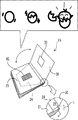
本発明の実施形態を添付の図面を参照して以下に詳細に説明する。図1は、本発明の一実施形態に係る冊子の構造を説明する分解斜視図である。 Embodiments of the present invention will be described in detail below with reference to the accompanying drawings. FIG. 1 is an exploded perspective view illustrating the structure of a booklet according to an embodiment of the present invention.
≪冊子全体の概略構造:図5≫
本発明の冊子は、製本後に本文(冊子内の各ページ)を構成する複数の折丁10を重ねて、その最上部に特殊折丁20を置き、これらを背糊および脇糊を用いて表紙30に固定し、最後に、背面部を除く三方を裁断して製本が完了する。
詳しくは後述するが、動画を生じさせる要素が特殊折丁20として提供されるため、一般的な大量生産ラインにのせて、動画を生じさせる冊子を製造することが可能となる。この効果は、「無線綴じ」または「アジロ綴じ」のいずれの手法で製本するかとは無関係に得られる。
<< Schematic structure of the entire booklet: Fig. 5 >>
The booklet of the present invention has a plurality of
As will be described in detail later, since an element that generates a moving image is provided as a
なお、「特殊折丁」とは、本文を構成する通常の折丁10に対して、「別の特殊な機能」を有する折丁という意味である。「特殊折丁」も勿論、製本後において、本文の一部を構成する。本発明における「別の特殊な機能」とは、動画を生じさせる機能である。
Note that “special signature” means a signature having “another special function” with respect to the
≪特殊折丁の構造:図6≫
図6を参照して、特殊折丁20の構造を説明する。特殊折丁20は、折罫a、b、cを介して一列に連設された第1区画21、第2区画22、第3区画23、第4区画24からなる1枚のブランクで構成される(図6a)。
≪Special signature structure: Fig. 6≫
The structure of the
第2区画22はベース区画を構成し、このベース区画22は、積み重ねられた他の折丁10の最上部に置かれる(図5)。
The
ベース区画22に対して、図6a中左側に連設された第1区画21は、フィルムゲージ保持区画を構成する。
すなわち、フィルムゲージ保持区画21には、矩形の開口21aが形成されていて、この開口21aを塞ぐようにして、フィルムゲージ45が貼り付けられる。
The
That is, a
ベース区画22に対して、図6a中右側に連設された第3区画23は、表紙30の内面に固定されるストローク付与区画を構成する。
すなわち、製本工程において、ストローク付与区画23は脇糊によって表紙30の内面に固定され、当該区画23の幅寸法に応じたスライドストローク量を下絵フラップ24に与える。詳しくは後述する。
A
That is, in the bookbinding step, the
ストローク付与区画23に対して、図6a中右側に連設された第4区画24は下絵フラップ24を構成する。この下絵フラップ24上に複合画像26が表示される。複合画像26は、下絵フラップ24上に直接印刷されていても、別のシート片に印刷したものを貼り付けてもよい。
A
特殊折丁20を組み立てるには、まず、下絵フラップ24をベース区画22上に折り返えす。次に、下絵フラップ24をスライド可能に挟み込むように、上方からフィルムゲージ保持区画21を折り返して、ベース区画22上に貼付・固定する。このとき、フィルムゲージ保持区画21は、ベース区画22の側方領域22aに貼り付けられ、したがって、台形形状の下絵フラップ24は、貼付後においても、ベース区画22とフィルムゲージ保持区画21とに挟まれた状態を保ってスライド移動が可能となる。
なお、折罫aのやや内側領域においても、フィルムゲージ保持区画21とベース区画22を接着固定しておくことが好ましく、これにより製本時に折罫aに沿う側辺領域を裁断した後でも、ベース区画22とフィルムゲージ保持区画21の自由端を接着固定した状態を保つことができる。
To assemble the
In addition, it is preferable that the film
なお、下に説明する通り、下絵フラップ24の適正なストローク量を確保するという観点からは、「アジロ綴じ」によって冊子を製本することが好ましい。その場合には、図6(a)に概略的に示したように、ベース区画22とストローク付与区画23の境界に位置する折罫bに、アジロ綴じ用のミシン目50を形成する。
As described below, from the viewpoint of securing an appropriate stroke amount of the
≪ストローク量を適正にするためにアジロ綴じが好ましい理由≫
まず、「無線綴じ」および「アジロ綴じ」について簡単に説明する。これらは、いずれも一般的に知られた製本手法である。
(1)無線綴じ
複数の折丁を重ね合わせて背面を合わせ、背糊および脇糊を用いて表紙に固定する。重ね合わせた折丁の背面に切込み60を形成して、背糊の付きを良くする(図7b)
(2)アジロ綴じ
これは無線綴じの改良で、重ね合わせた折丁の背面において、無線綴じの場合の上記切込み60に代えてミシン目50を設けている。(図7a)ミシン目50を通して、折丁の中にまで糊が侵入するので、接着力が高くなるというメリットがある。
≪Reasons why azimuth binding is preferable to make the stroke amount appropriate≫
First, “wireless binding” and “Ajiro binding” will be briefly described. These are all generally known bookbinding techniques.
(1) Perfect binding A plurality of signatures are overlapped, the backs are aligned, and fixed to the cover using back glue and side glue. A
(2) Ajiro binding This is an improvement of the perfect binding, and a
図7に一部拡大して示したように、折丁背面からの切除部の深さを比較すると、「アジロ綴じにおけるミシン目50」の深さD1は小さいが、「無線綴じにおける切込み60」の深さD2は、D1よりもかなり大きい。
このように、深さD1が小さいことがアジロ綴じが好ましい理由である。図8を参照して詳しく説明する。
As shown in a partially enlarged view in FIG. 7, when comparing the depth of the cut portion from the back of the signature, the depth D1 of the “
Thus, it is the reason why azimuth binding is preferable because the depth D1 is small. This will be described in detail with reference to FIG.
図8は、冊子断面を示す模式図である。背面を合わせて重ね合わされた折丁10および特殊折丁20は、背糊と脇糊を用いて表紙30に固定される。
特殊折丁20のストローク付与区画23に脇糊が塗布される。つまり、ストローク付与区画23は、表紙内面に接着・固定されるので、製本後における表紙30の開閉操作の際に、表紙30と一緒に移動する。そして、これに連動して下絵フラップ24が、フィルムゲージ保持区画21に保持されたフィルムゲージ45に対して相対的にスライドする。
このように、ストローク付与区画23の幅寸法“L”によって、下絵フラップ24がスライド移動する場合のストローク量が決定される。“L”の具体的な寸法は、動画の種類に応じて個別に設定されるが、いずれにしても予め設定した“L”の値が正確に実現されることが重要となる。
FIG. 8 is a schematic view showing a booklet cross section. The
Side glue is applied to the
Thus, the stroke amount when the
一方、図8において、“D”は背面からの背糊の侵入量を示している。既に説明したように、積み重ねた折丁の背面に、「アジロ綴じ」ではミシン目50を、「無線綴じ」では切込み60を、形成している。そのため、その部分から背糊が侵入して脇糊領域に入り込んでくる。
この侵入量“D”に相当する領域では、表紙30が冊子内の各折丁と一体化するので、表紙30を開閉する動作を行っても、当該領域における表紙部分は、各折丁と一体化するため動かない。つまり、“D”に相当する距離だけストロークに寄与する脇糊領域が殺され、その結果、ストロークに寄与できる実質的な脇糊幅は「L−D」となってしまう。
すなわち、動画の設計段階で“L”のストローク量を予定していたにも拘わらず、実際のストローク量は「L−D」となってしまい、その結果、得られる動画のダイナミックさが不十分なものとなってしまう。
On the other hand, in FIG. 8, “D” indicates the amount of back glue entering from the back. As described above, the
In the area corresponding to the intrusion amount “D”, the
In other words, although the “L” stroke amount is planned at the moving image design stage, the actual stroke amount becomes “LD”, and as a result, the dynamic of the obtained moving image is insufficient. It will become something.
これを避けるためには、“D”の値はできるだけ小さい方が好ましい。ここで図7に戻ると、この“D”は、アジロ綴じにおいては“D1”、無線綴じにおいては“D2”となるので、アジロ綴じの方が好ましいことが分かる。 In order to avoid this, it is preferable that the value of “D” is as small as possible. Returning to FIG. 7, “D” is “D1” in azimuth binding and “D2” in wireless binding, and it is understood that azimuth binding is preferable.
≪下絵フラップ24の台形形状について≫
図示した実施形態では、動画を生じさせる特殊折丁20を含んだ冊子を大量生産にさらに適したものとするために、下絵フラップ24の形状を富士山のような台形形状としている。
すなわち、図6に示したように、下絵フラップ24は、ストローク付与区画23に連設される根元部24aにおいては、ストローク付与区画23の全高に渡って延在する(製本後の冊子の天地方向全体に渡って延在する)。一方、根元部24aとは反対側の自由端部24bは、下絵フラップ24のスライド移動を可能とするために、根元部24bよりも短い寸法を有する。
そして、根元部24aと自由端部24bの両端同士をそれぞれ直線24cで結び、全体として台形形状を為している。
≪About trapezoidal shape of
In the illustrated embodiment, the shape of the
That is, as shown in FIG. 6, the
Then, both ends of the
これには、次のような理由がある。製本機械を用いて特殊折丁20を折り畳む際には、まず機械のアームが自由端部24bを掴んで下絵フラップ24を折り返す。このとき、下絵フラップ24は湾曲アーチ状に折り返された状態にあるが、その後、折罫b、cに沿って機械的に鋭角の折り目が付けられる。つまり、機械アームが摘むのは幅狭の自由端部24bだけであるが、このアームによる摘み力を幅広の根元部24a全体に良好に伝えるには、自由端部24bの両端を根元部24aの両端まで直線24cで連結し、全体として台形形状とすることが好ましい。
直線24cが内側に入り込むと、アームによる摘み力が根元部24aの両端領域に良好に伝わらず、良好に折り返すことができない。一方、直線24cが外側に膨出すると、特殊折丁20の組立後において、下絵フラップ24のスムーズなスライド移動を阻害してしまう。
下絵フラップ24を直線で囲まれた台形形状とすることで、いずれの不都合もなく、機械による大量生産を実現することが可能となる。
There are the following reasons for this. When the
When the
By making the
≪生じる動画との関係≫
図9は、製本後の冊子15と、生じる動画との関係を示している。表紙30を閉じたり開いたりする動作に伴って、下絵フラップ24がフィルムゲージ45に対して相対的にスライド移動し、これによって、視覚的効果を利用した動画が現れる。図9では、3つの画素から構成される動画の一例を示しているが、具体的な図柄や画素の数は、任意に設定することができる。
生じる動画を、当該冊子の内容あるいは出版社と関連付けたものとすることで、宣伝効果あるいは販売促進効果を高めることができる。この関連性は、当該冊子の内容や出版社に直接関連するものに限られず、広い意味で何らかの関連があればよい。
≪Relationship with the resulting video≫
FIG. 9 shows the relationship between the
By associating the generated moving image with the contents of the booklet or the publisher, the advertising effect or the sales promotion effect can be enhanced. This relevance is not limited to those directly related to the contents of the booklet or the publisher, but may be any relevance in a broad sense.
なお、図示した例では表紙30に窓33を設けているが、この窓33は必ずしも必要ではなく、省略することも可能である。しかし、窓33が存在すると、冊子の表紙30を開いたり、閉じたりする動作に伴って、より広範な角度からフィルムゲージの上に生じる動画を視認することができるというメリットがある。この構成は、特に冊子の陳列状態において、動画装飾要素の存在をアピールして、販売促進効果が期待できるという点で有利である。
In the illustrated example, the window 33 is provided on the
≪格子状のフィルムゲージ≫
本発明においては、ストライプ状のフィルムゲージ45に限らず、格子状のフィルムゲージ45’を採用することも可能である(図6中の円内)。勿論、その場合には、下絵26は、これに対応して動画を生じさせるものが採用される。
ストライプ状のフィルムゲージ45の場合、一方向の相対スライドによって動画が生じるが、格子状のフィルムゲージ45’の場合、タテ、ヨコ、ナナメのいずれの方向に相対スライドした場合でも動画が生じる。これは、特殊折丁20の組立て精度が高くなく、相対スライド方向が予定の一方向から逸れた場合でも動画に変化が生じるという点で有効である。
≪Lattice film gauge≫
In the present invention, not only the stripe-shaped
In the case of the stripe-shaped
≪下絵フラップとフィルムゲージとの密着性を高めるための構成:図9≫
さらに本発明においては、特殊折丁20にストローク付与区画23を設けていることに起因して、下絵フラップ24とフィルムゲージ45との密着性が高まるというメリットがある。
一般的に、下絵フラップ24とフィルムゲージ45を重ねて相対スライドさせることで動画を生じさせる場合、両者の隙間が大きいと、動画がボヤケて見えることがある。動画をクリアにするためには、下絵フラップ24とフィルムゲージ45が適度に圧接することが好ましい。
≪Configuration for improving adhesion between background flap and film gauge: Fig. 9≫
Furthermore, in the present invention, there is an advantage that the adhesion between the
In general, when a moving image is generated by overlapping and sliding the
図9に部分的に拡大して示したように、ストローク付与区画23が存在するが故に、下絵フラップ24は、表紙30の内面において、折罫bから一定距離“L”だけ離れた位置から立ち上がることとなる(オフセットされている)。これにより、下絵フラップ24をフィルムゲージ45に対して圧接させる力が生じる。つまり、下絵フラップ24とフィルムゲージ45が適度に密着して、クリアな動画を得ることができる。
As shown in a partially enlarged view in FIG. 9, since the
10 折丁
15 冊子
20 特殊折丁
21 フィルムゲージ保持区画(第1区画)
21a 開口
22 ベース区画(第2区画)
23 ストローク付与区画(第3区画)
24 下絵フラップ(第4区画)
26 複合画像
30 表紙
33 開口(窓)
45 フィルムゲージ
50 ミシン目
60 切込み
10
23 Stroke section (third section)
24 Background flap (4th section)
26
45
Claims (5)
複合画像(26)で構成される下絵が表示された下絵フラップ(24)と、当該下絵に対応するフィルムゲージ(45)とを重ね、両者を相対的にスライド移動させることで、動画を生じさせる特殊折丁であって、
当該特殊折丁は、折罫を介して一列に連設された第1〜第4区画で構成され、
第1区画(21)は、フィルムゲージ(45)を保持するフィルムゲージ保持区画(21)を構成し、
第2区画(22)は、折丁(10)の上に重ねられるベース区画(22)を構成し、
第3区画(23)は、脇糊によって冊子の表紙(30)内面に固定されるストローク付与区画(23)を構成し、
第4区画(24)は、下絵フラップ(24)を構成し、
下絵フラップ(24)がベース区画(22)上に折り返されるとともに、当該下絵フラップ(24)をスライド可能に挟み込むように、フィルムゲージ保持区画(23)が折り返されてベース区画(22)上に固定されており、
製本された冊子の表紙(30)を開閉すると、表紙内面に固定されたストローク付与区画(23)が共に移動し、これと連動して下絵フラップ(24)がフィルムゲージ(45)に対して相対的にスライドして、上記動画が生じることを特徴とする、特殊折丁。
Overlaid on the signature (10), fixed to the cover (30) with back glue and side glue to form a booklet (15),
A sketch flap (24) on which a sketch composed of a composite image (26) is displayed and a film gauge (45) corresponding to the sketch are overlapped, and both are relatively slid to generate a moving image. Special signature,
The special signature is composed of first to fourth sections arranged in a row through a crease,
The first section (21) constitutes a film gauge holding section (21) for holding the film gauge (45),
The second compartment (22) constitutes a base compartment (22) overlaid on the signature (10),
The third section (23) constitutes a stroke application section (23) fixed to the inner surface of the booklet cover (30) by side glue,
The fourth section (24) constitutes a background flap (24),
The base flap (24) is folded back onto the base section (22), and the film gauge holding section (23) is folded back and fixed on the base section (22) so that the base flap (24) is slidably sandwiched. Has been
When the cover (30) of the bound booklet is opened and closed, the stroke applying section (23) fixed to the inner surface of the cover is moved together, and the background flap (24) is relative to the film gauge (45) in conjunction with this. A special signature, characterized by the fact that the above-mentioned moving image is generated by sliding.
The base flap (24) extends across the entire width of the stroke application section (23) in the root section (24a) connected to the stroke application section (23) and is opposite to the root section. The free end portion (24b) has a dimension shorter than the full width, and has a trapezoidal shape in which both ends of the root portion (24a) and the free end portion (24b) are connected by a straight line (24c). The special signature according to claim 1.
The crease (b) located at the boundary between the base section (22) and the stroke applying section (23) is formed with a perforation (50) for azimuth binding. 2. Special signature described in 2.
特殊折丁(20)のストローク付与区画(23)が脇糊で表紙内面に固定されており、表紙(30)を開閉する動作と連動して下絵フラップ(24)がフィルムゲージ(45)に対して相対的にスライドし、これにより上記動画が生じることを特徴とする、冊子。
A booklet that is bound and bound to the cover (30) using back glue and side glue after the special signature (20) according to claim 3 is stacked on the signature (10). ,
The stroke applying section (23) of the special signature (20) is fixed to the inner surface of the cover with side glue, and the background flap (24) is attached to the film gauge (45) in conjunction with the opening and closing operation of the cover (30). The booklet is characterized in that the above-mentioned moving image is generated by relatively sliding.
Priority Applications (1)
| Application Number | Priority Date | Filing Date | Title |
|---|---|---|---|
| JP2008250896A JP5169692B2 (en) | 2008-09-29 | 2008-09-29 | Special signatures that produce movies, and booklets with them |
Applications Claiming Priority (1)
| Application Number | Priority Date | Filing Date | Title |
|---|---|---|---|
| JP2008250896A JP5169692B2 (en) | 2008-09-29 | 2008-09-29 | Special signatures that produce movies, and booklets with them |
Publications (2)
| Publication Number | Publication Date |
|---|---|
| JP2010082806A true JP2010082806A (en) | 2010-04-15 |
| JP5169692B2 JP5169692B2 (en) | 2013-03-27 |
Family
ID=42247264
Family Applications (1)
| Application Number | Title | Priority Date | Filing Date |
|---|---|---|---|
| JP2008250896A Active JP5169692B2 (en) | 2008-09-29 | 2008-09-29 | Special signatures that produce movies, and booklets with them |
Country Status (1)
| Country | Link |
|---|---|
| JP (1) | JP5169692B2 (en) |
Cited By (2)
| Publication number | Priority date | Publication date | Assignee | Title |
|---|---|---|---|---|
| JP2010120364A (en) * | 2008-10-24 | 2010-06-03 | Dainippon Printing Co Ltd | Special signature for producing animation, and booklet equipped with the same |
| JP2012000965A (en) * | 2010-06-21 | 2012-01-05 | Liberal:Kk | Book with printed image appearing to move |
Citations (8)
| Publication number | Priority date | Publication date | Assignee | Title |
|---|---|---|---|---|
| US2367967A (en) * | 1942-11-18 | 1945-01-23 | Schwartz Edward | Animated picture device |
| JPS4931419U (en) * | 1972-06-19 | 1974-03-18 | ||
| JPS5149053Y1 (en) * | 1970-10-16 | 1976-11-26 | ||
| JPS614700U (en) * | 1984-06-14 | 1986-01-11 | スミダ紙工株式会社 | variable painting |
| JPH0686797U (en) * | 1993-05-31 | 1994-12-20 | 株式会社パオパオ | Switching display tool |
| JP2000108467A (en) * | 1998-10-06 | 2000-04-18 | Dainippon Screen Mfg Co Ltd | Image displaying device, printing and book binding device using the same, and recording medium |
| JP2001150835A (en) * | 1999-11-26 | 2001-06-05 | Toppan Printing Co Ltd | Deluxe edition and method for making the same |
| JP2007526500A (en) * | 2004-01-08 | 2007-09-13 | セデル,ルフス,ブトラー | Movable video display |
-
2008
- 2008-09-29 JP JP2008250896A patent/JP5169692B2/en active Active
Patent Citations (8)
| Publication number | Priority date | Publication date | Assignee | Title |
|---|---|---|---|---|
| US2367967A (en) * | 1942-11-18 | 1945-01-23 | Schwartz Edward | Animated picture device |
| JPS5149053Y1 (en) * | 1970-10-16 | 1976-11-26 | ||
| JPS4931419U (en) * | 1972-06-19 | 1974-03-18 | ||
| JPS614700U (en) * | 1984-06-14 | 1986-01-11 | スミダ紙工株式会社 | variable painting |
| JPH0686797U (en) * | 1993-05-31 | 1994-12-20 | 株式会社パオパオ | Switching display tool |
| JP2000108467A (en) * | 1998-10-06 | 2000-04-18 | Dainippon Screen Mfg Co Ltd | Image displaying device, printing and book binding device using the same, and recording medium |
| JP2001150835A (en) * | 1999-11-26 | 2001-06-05 | Toppan Printing Co Ltd | Deluxe edition and method for making the same |
| JP2007526500A (en) * | 2004-01-08 | 2007-09-13 | セデル,ルフス,ブトラー | Movable video display |
Cited By (2)
| Publication number | Priority date | Publication date | Assignee | Title |
|---|---|---|---|---|
| JP2010120364A (en) * | 2008-10-24 | 2010-06-03 | Dainippon Printing Co Ltd | Special signature for producing animation, and booklet equipped with the same |
| JP2012000965A (en) * | 2010-06-21 | 2012-01-05 | Liberal:Kk | Book with printed image appearing to move |
Also Published As
| Publication number | Publication date |
|---|---|
| JP5169692B2 (en) | 2013-03-27 |
Similar Documents
| Publication | Publication Date | Title |
|---|---|---|
| JP5169692B2 (en) | Special signatures that produce movies, and booklets with them | |
| JP5146213B2 (en) | Video card | |
| JP2006315376A5 (en) | ||
| JP5223569B2 (en) | Booklet with decorative elements that produce a video | |
| JP2010228340A (en) | Moving image sheet and moving image book | |
| JP5902822B2 (en) | Method for producing a printed product comprising at least three partial products | |
| JP5218010B2 (en) | Special signatures that produce movies, and booklets with them | |
| JP5239557B2 (en) | Packaging box | |
| US20150224805A1 (en) | Publication and method of making a publication | |
| JPH04173399A (en) | Method for forming booklet-like calendar and calendar paper capable of forming said calendar | |
| JP5239558B2 (en) | Packaging box | |
| JP5304056B2 (en) | Packaging box | |
| JP5338158B2 (en) | Free sample package | |
| JP5928996B2 (en) | Variable image display | |
| JP6804750B2 (en) | Stereoscopic image display device and its seat members | |
| JP5165783B2 (en) | tag | |
| JP4820212B2 (en) | Standing up case | |
| JP6244275B2 (en) | Packaging box and its blank sheet | |
| JP2014233840A (en) | Sheet file with index tab and combination thereof | |
| JP3180190U (en) | Sliding image display | |
| JP6194243B2 (en) | Folding sheet and manufacturing method thereof | |
| JP2018062097A (en) | Print material for notepad and method of fabricating notepad | |
| JP3215134U (en) | Clear file with heading on the back | |
| JP3210499U (en) | Folded file | |
| GB2421348A (en) | Stiffening rod for a graphic display system |
Legal Events
| Date | Code | Title | Description |
|---|---|---|---|
| A621 | Written request for application examination |
Free format text: JAPANESE INTERMEDIATE CODE: A621 Effective date: 20110818 |
|
| A977 | Report on retrieval |
Free format text: JAPANESE INTERMEDIATE CODE: A971007 Effective date: 20121127 |
|
| TRDD | Decision of grant or rejection written | ||
| A01 | Written decision to grant a patent or to grant a registration (utility model) |
Free format text: JAPANESE INTERMEDIATE CODE: A01 Effective date: 20121204 |
|
| A61 | First payment of annual fees (during grant procedure) |
Free format text: JAPANESE INTERMEDIATE CODE: A61 Effective date: 20121217 |
|
| R150 | Certificate of patent or registration of utility model |
Ref document number: 5169692 Country of ref document: JP Free format text: JAPANESE INTERMEDIATE CODE: R150 |