JP2010082725A - Hole saw - Google Patents
Hole saw Download PDFInfo
- Publication number
- JP2010082725A JP2010082725A JP2008252557A JP2008252557A JP2010082725A JP 2010082725 A JP2010082725 A JP 2010082725A JP 2008252557 A JP2008252557 A JP 2008252557A JP 2008252557 A JP2008252557 A JP 2008252557A JP 2010082725 A JP2010082725 A JP 2010082725A
- Authority
- JP
- Japan
- Prior art keywords
- hole saw
- cutting
- blade body
- metal plate
- concrete structure
- Prior art date
- Legal status (The legal status is an assumption and is not a legal conclusion. Google has not performed a legal analysis and makes no representation as to the accuracy of the status listed.)
- Granted
Links
Images


Landscapes
- Drilling Tools (AREA)
Abstract
Description
本発明は、コンクリートやレンガの構造物或いはコンクリートパネル等(以下、これらを単にコンクリート構造物等という)の表面を覆う金属板、コンクリート構造物等の奥側の金属部分、或いは厚みのある金属自体へ深い穴あけ加工を行うのに用いるホールソーに関する。 The present invention relates to a metal plate that covers the surface of a concrete or brick structure or concrete panel (hereinafter simply referred to as a concrete structure), a metal part on the back side of the concrete structure, or a thick metal itself. The present invention relates to a hole saw used for deep hole drilling.
図1は、下記特許文献1に開示される従来のホールソーの代表的な例を示すもので、ホーソー1は円筒状のボデー2と、該ボデー先端の切り刃3からなる円筒状刃物4と、該円筒状刃物4に取付けられるホールソー取付部5と、ホールソー取付部5に取付けられるシャンク部6と、ホールソー取付部5に取付けられ、穴あけ時にセンターのガイドピンとして用いられるセンターガイドドリル7を備えている。
前述する従来のホールソー1は、ボデー2の肉厚が1mm前後と薄いため、
(1)剛性不良により長く伸ばすと強度不足になり、深い穴あけ加工、とくに鉄鋳物や非鉄鋳物のインゴット、船舶のスクリューなど厚みのある金属への穴あけ加工ができない、
(2)ボデー2にチューブを継ぎ足して延長したくても、ボデー2の肉厚が薄いため、連結用のネジを形成することができず、そのためコンクリート構造物等の奥側にある金属部分への穴あけ加工等ができない、
(3)表面が金属板で覆われるコンクリート構造物等に穴あけ加工を行う場合、金属板に穴あけ後、コアビットによりコンクリート構造物等に穴あけ加工を行おうとすると、ホールソーによって形成された金属板の切削溝が細いため、ホールソーよりも厚みのあるコアビットを通すことができず、そのため円形に切り抜かれたコア状の金属板を取り除かねばならないが、金属板がコンクリート構造物等内の鉄筋などに取着されていると、金属板を剥がすことができない、
などの不具合がある。
本発明は、前述する不具合を解消することができるホールソーを提供することを目的とする。
In the conventional hole saw 1 described above, the thickness of the
(1) If stretched for a long time due to poor rigidity, the strength becomes insufficient, and deep drilling, especially ingots of iron castings and non-ferrous castings, drilling to thick metals such as ship screws, can not be done.
(2) Even if you want to add a tube to the
(3) When drilling a concrete structure, etc. whose surface is covered with a metal plate, after drilling in the metal plate after drilling in the metal plate, cutting the metal plate formed by the hole saw Because the groove is narrow, it is not possible to pass a core bit thicker than a hole saw, so the core metal plate cut out in a circle must be removed, but the metal plate is attached to the reinforcing bar in a concrete structure etc. The metal plate cannot be peeled off,
There are problems such as.
An object of this invention is to provide the hole saw which can eliminate the malfunction mentioned above.
請求項1に係わる発明のホールソーは、一側外周にネジが形成される円筒状のシャンク部と、該シャンク部の他端に固着され、二重管構造を構成する円筒状の内刃ボデー及び外刃ボデーを有し、各ボデーの先端にはそれぞれ切り刃が設けられることを特徴とし、
請求項2に係わる発明のホールソーは、請求項1に係わる発明のホールソーにおいて、内刃ボデーの切り刃が外刃ボデーの切り刃より筒軸方向に突出することを特徴とする。
A hole saw according to a first aspect of the present invention includes a cylindrical shank portion having a screw formed on one outer periphery thereof, a cylindrical inner blade body that is fixed to the other end of the shank portion, and forms a double tube structure, and It has an outer blade body, and a cutting blade is provided at the tip of each body,
A hole saw according to a second aspect of the invention is characterized in that, in the hole saw according to the first aspect of the invention, the cutting blade of the inner blade body projects in the cylinder axis direction from the cutting blade of the outer blade body.
請求項3に係わる発明のホールソーは、請求項1又は2に係わる発明のホールソーがコアビットに付け替えて用いられることを特徴とする。
The hole saw of the invention according to claim 3 is characterized in that the hole saw of the invention according to
請求項1に係わる発明のホールソーによると、シャンク部は一側にネジが形成され、同じ厚みのチューブを継ぎ足して長く延ばして使用することができること、ネジを形成することができない従来のホールソーに比べ、ネジが形成できるほど厚肉であるため剛性が増し、長く形成しても、また同じ厚みのチューブを継ぎ足しても強度を維持することができ、そのため厚みのある金属或いはコンクリート構造物等の奥側にある金属部分への穴あけ加工も可能となること、金属部分への穴あけ加工は、コアドリルのような高出力の固定式ドリルを用いて行われるが、ホールソーが従来のものに比べ剛性を有しているため、振動や騒音を生じにくく、またコアドリルのパワーに負けてボデーが変形する、といった弊害を生じにくいこと、表面が金属板で覆われるコンクリート構造物等に穴あけ加工を行う場合、ホールソーを用いて金属板に穴あけを行ったのち、コンクリート構造物等への穴あけ加工に用いるコアビットや超硬式ホールソー(これらを以下単にコアビット等という)を用いてコンクリート構造物等への穴あけを行うが、内外二重の刃先を備えたホールソーで形成された金属板の切削溝は広いため、環状の切削溝によって形成されるコア状の金属板を取り除くことなく、また金属板がコンクリート構造物等内の鉄筋に取着されていてもコアビットを用いて、或いはホールソーをコアビットに付け替えてコンクリート構造物等への穴あけを支障なく続行することができること等の効果を奏する。 According to the hole saw of the invention according to claim 1, the shank portion is formed with a screw on one side, and can be used by extending the tube with the same thickness and extending long, compared to a conventional hole saw that cannot form a screw. The thickness is so thick that a screw can be formed, so that the rigidity is increased, and even if it is formed long, or even if a tube with the same thickness is added, the strength can be maintained, so that the depth of a thick metal or concrete structure etc. Drilling in the metal part on the side is also possible, and drilling in the metal part is performed using a high-power fixed drill such as a core drill, but the hole saw has rigidity compared to the conventional one. Therefore, vibration and noise are less likely to occur, and the body is less likely to be deformed by losing the power of the core drill. When drilling holes in a concrete structure, etc. covered with metal, drill a hole in a metal plate using a hole saw, and then use a core bit or carbide hole saw (these are simply called core bits, etc.) used for drilling holes in a concrete structure, etc. ) Is used to drill into concrete structures, etc., but since the cutting groove of the metal plate formed by the hole saw with the inner and outer double cutting edges is wide, the core-shaped metal plate formed by the annular cutting groove Drilling holes in a concrete structure can be continued without hindrance by using a core bit or replacing a hole saw with a core bit even if the metal plate is attached to a reinforcing bar in the concrete structure. There are effects such as.
請求項2に係わる発明によると、切込時の切り刃のブレを少なくすることができる。すなわち内外の切り刃が筒軸方向に揃って同じ位置にあると、切込時に両切り刃が同時に被削材に当たることから、切り刃のブレが大きくなり、切り刃が安定するまで切込むのにかなりな時間を要するのに対し、本発明のように内側の切り刃を外側の切り刃より筒軸方向に突出させると、先ず内側の切り刃が被削材に当たって食い込むため、切り刃のブレが少なくなり、比較的短時間で切り刃を安定させることができること、外側の切り刃が切込みを開始する時点では、内側の切り刃が被削材に食い込んで回転中心が固定された状態となり、内側の切り刃がガイドとなって外側の切り刃による被削材への切込みがスムースに行えるようになること等の効果を奏する。
According to the
請求項3に係わる発明によると、ホールソーとコアビットの付け替えを行うことにより、同じコアドリルを用いてコンクリート構造物等や金属部分の穴あけ加工を行うことができる。 According to the invention relating to claim 3, by exchanging the hole saw and the core bit, it is possible to drill a concrete structure or the like or a metal part using the same core drill.
以下、本発明の実施形態のホールソーについて図面により説明する。
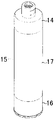
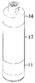
図2は、本発明に係わるホールソー11の正面図、図3は同側面図、図4は同断面図で、円筒状のシャンク部12は一側外周にネジ13が形成され、図5に示すコアドリル用コアビットのカップリング14にコアビットに替えて捩込んで取付けられるか、或いは図6に示すようにカップリング14とコアビット16をチューブ17を介して連結した連結式コアビット15のコアビット16に替えてチューブ17に捩込んで取付けられるようになっている(図7)。
Hereinafter, a hole saw according to an embodiment of the present invention will be described with reference to the drawings.
2 is a front view of a hole saw 11 according to the present invention, FIG. 3 is a side view thereof, FIG. 4 is a cross-sectional view thereof, and a
シャンク部12は他端に円筒状の内刃ボデー18と外刃ボデー19が固着されて、両ボデー18及び19が二重管構造を構成している。そして各ボデー18及び19の先端には切り刃21及び22が形成され、内刃ボデー18の切り刃21は外刃ボデー19の切り刃22より筒軸方向に突出している。
The
本実施形態のホールソーによると、シャンク部11はほぼ内刃ボデー18と外刃ボデー19の肉厚を合わせた肉厚を有し、片方のボデー18又は19のみの肉厚を有する従来のホールソーに比べ、肉厚がほぼ倍増するため剛性が増すと共に、ネジ12を形成することができ、そのため長く伸ばしたり、チューブ17に捩じ込んで継ぎ足しても強度を維持することが可能で、したがって厚みのある金属或いはコンクリート構造物等の奥側にある金属部分への穴あけ加工が可能となり、コアドリルのような高出力の固定式ドリルに取付けて用いても、振動や騒音を生じにくく、また高出力のドリルのパワーに負けてボデーが変形する、といった弊害も生じないこと、表面が金属板で覆われるコンクリート構造物等に穴あけ加工を行う場合、金属板に形成される切削溝の幅を広くできるため、金属板を取付けたままでコアビット等を用いてコンクリート構造物等への穴あけ加工を行うことができること、被削材への切込時には両切り刃が同時に被削材に当たるよりも片側の切り刃だけが被削材に当たる方が切込み易く、ブレも少なくなるが、本実施形態では内側の切り刃が先に被削材に当たって食い込むため、切り刃のブレが少なくなり、切込時、比較的短時間で切り刃を安定させることができること、外側の切り刃が切込みを開始する時点では、内側の切り刃が被削材に食い込んで回転中心が固定された状態となり、内側の切り刃がガイドとなって外側の切り刃による被削材への切込みがスムースに行えるようになること、図1に示す従来のホールソーのようなセンターガイドドリル7が不要であること等の効果を奏する。また本発明者らの実験によると、内外の切り刃に段差を設けることにより、段差を設けないホールソーに比べ、切粉の排出がスムースに行えることが確認された。
According to the hole saw of the present embodiment, the
11・・ホールソー
12・・シャンク部
13・・ネジ
14・・カップリング
15・・連結式コアビット
16・・コアビット
17・・チューブ
18・・内刃ボデー
19・・外刃ボデー
21、22・・切り刃
11. · Hole saw 12 · Shank
Claims (3)
Priority Applications (1)
| Application Number | Priority Date | Filing Date | Title |
|---|---|---|---|
| JP2008252557A JP5313611B2 (en) | 2008-09-30 | 2008-09-30 | Hole saw |
Applications Claiming Priority (1)
| Application Number | Priority Date | Filing Date | Title |
|---|---|---|---|
| JP2008252557A JP5313611B2 (en) | 2008-09-30 | 2008-09-30 | Hole saw |
Publications (2)
| Publication Number | Publication Date |
|---|---|
| JP2010082725A true JP2010082725A (en) | 2010-04-15 |
| JP5313611B2 JP5313611B2 (en) | 2013-10-09 |
Family
ID=42247195
Family Applications (1)
| Application Number | Title | Priority Date | Filing Date |
|---|---|---|---|
| JP2008252557A Active JP5313611B2 (en) | 2008-09-30 | 2008-09-30 | Hole saw |
Country Status (1)
| Country | Link |
|---|---|
| JP (1) | JP5313611B2 (en) |
Cited By (1)
| Publication number | Priority date | Publication date | Assignee | Title |
|---|---|---|---|---|
| KR20210009781A (en) * | 2019-07-18 | 2021-01-27 | 박도준 | Hole cutter |
Citations (4)
| Publication number | Priority date | Publication date | Assignee | Title |
|---|---|---|---|---|
| JPS62111811U (en) * | 1985-12-30 | 1987-07-16 | ||
| JPS63163913U (en) * | 1987-04-15 | 1988-10-26 | ||
| JPH04125511U (en) * | 1991-05-08 | 1992-11-16 | エイド技研工業株式会社 | drilling drill bit |
| JP2007290112A (en) * | 2006-03-31 | 2007-11-08 | Nicotec Co Ltd | Holesaw, and method for bending set in holesaw |
-
2008
- 2008-09-30 JP JP2008252557A patent/JP5313611B2/en active Active
Patent Citations (4)
| Publication number | Priority date | Publication date | Assignee | Title |
|---|---|---|---|---|
| JPS62111811U (en) * | 1985-12-30 | 1987-07-16 | ||
| JPS63163913U (en) * | 1987-04-15 | 1988-10-26 | ||
| JPH04125511U (en) * | 1991-05-08 | 1992-11-16 | エイド技研工業株式会社 | drilling drill bit |
| JP2007290112A (en) * | 2006-03-31 | 2007-11-08 | Nicotec Co Ltd | Holesaw, and method for bending set in holesaw |
Cited By (2)
| Publication number | Priority date | Publication date | Assignee | Title |
|---|---|---|---|---|
| KR20210009781A (en) * | 2019-07-18 | 2021-01-27 | 박도준 | Hole cutter |
| KR102609691B1 (en) * | 2019-07-18 | 2023-12-05 | 박도준 | Hole cutter |
Also Published As
| Publication number | Publication date |
|---|---|
| JP5313611B2 (en) | 2013-10-09 |
Similar Documents
| Publication | Publication Date | Title |
|---|---|---|
| KR101130496B1 (en) | Multi functional cutting tool | |
| WO2011108108A1 (en) | Cutting tool | |
| JP2007290112A (en) | Holesaw, and method for bending set in holesaw | |
| JP6383092B2 (en) | drill | |
| JP2002144124A (en) | Small drill | |
| JP2010082725A (en) | Hole saw | |
| JP2004268165A (en) | Deep hole machining drill | |
| JP2010082812A (en) | Core bit | |
| JP2005161434A (en) | Drill | |
| CN214161641U (en) | Reverse scraper | |
| JP2009018384A (en) | Drill | |
| JP2006263831A (en) | Tool holder | |
| JP2008023607A (en) | Gun drill and drill body attached thereto | |
| JP2009034735A (en) | Three-groove drill | |
| JP2011121132A (en) | Repeater type cutting tool | |
| JP2007290105A (en) | End mill | |
| JP2004345081A (en) | Rotary cutting tool | |
| JP4843317B2 (en) | Long drill with guide | |
| JP2007333026A (en) | Drill screw with pilot length | |
| JP2006150509A (en) | Cutting tool | |
| JP5034528B2 (en) | Rotary cutting tool for punching holes | |
| JP2006150508A (en) | Cutting tool | |
| JP2005138258A (en) | Drill | |
| JP2005022012A (en) | Drill | |
| JP2005118929A (en) | Steel arbor for mounting rotating tool |
Legal Events
| Date | Code | Title | Description |
|---|---|---|---|
| A621 | Written request for application examination |
Free format text: JAPANESE INTERMEDIATE CODE: A621 Effective date: 20110622 |
|
| A131 | Notification of reasons for refusal |
Free format text: JAPANESE INTERMEDIATE CODE: A131 Effective date: 20130108 |
|
| A521 | Request for written amendment filed |
Free format text: JAPANESE INTERMEDIATE CODE: A523 Effective date: 20130221 |
|
| TRDD | Decision of grant or rejection written | ||
| A01 | Written decision to grant a patent or to grant a registration (utility model) |
Free format text: JAPANESE INTERMEDIATE CODE: A01 Effective date: 20130702 |
|
| A61 | First payment of annual fees (during grant procedure) |
Free format text: JAPANESE INTERMEDIATE CODE: A61 Effective date: 20130704 |
|
| R150 | Certificate of patent or registration of utility model |
Ref document number: 5313611 Country of ref document: JP Free format text: JAPANESE INTERMEDIATE CODE: R150 Free format text: JAPANESE INTERMEDIATE CODE: R150 |
|
| R250 | Receipt of annual fees |
Free format text: JAPANESE INTERMEDIATE CODE: R250 |
|
| R250 | Receipt of annual fees |
Free format text: JAPANESE INTERMEDIATE CODE: R250 |
|
| R250 | Receipt of annual fees |
Free format text: JAPANESE INTERMEDIATE CODE: R250 |
|
| R250 | Receipt of annual fees |
Free format text: JAPANESE INTERMEDIATE CODE: R250 |