JP2010081757A - Battery, battery control method, charger, electric apparatus, charge control system, and discharge control system - Google Patents
Battery, battery control method, charger, electric apparatus, charge control system, and discharge control system Download PDFInfo
- Publication number
- JP2010081757A JP2010081757A JP2008248700A JP2008248700A JP2010081757A JP 2010081757 A JP2010081757 A JP 2010081757A JP 2008248700 A JP2008248700 A JP 2008248700A JP 2008248700 A JP2008248700 A JP 2008248700A JP 2010081757 A JP2010081757 A JP 2010081757A
- Authority
- JP
- Japan
- Prior art keywords
- temperature
- battery
- battery cell
- discharge
- circuit
- Prior art date
- Legal status (The legal status is an assumption and is not a legal conclusion. Google has not performed a legal analysis and makes no representation as to the accuracy of the status listed.)
- Granted
Links
Images


Classifications
-
- Y—GENERAL TAGGING OF NEW TECHNOLOGICAL DEVELOPMENTS; GENERAL TAGGING OF CROSS-SECTIONAL TECHNOLOGIES SPANNING OVER SEVERAL SECTIONS OF THE IPC; TECHNICAL SUBJECTS COVERED BY FORMER USPC CROSS-REFERENCE ART COLLECTIONS [XRACs] AND DIGESTS
- Y02—TECHNOLOGIES OR APPLICATIONS FOR MITIGATION OR ADAPTATION AGAINST CLIMATE CHANGE
- Y02E—REDUCTION OF GREENHOUSE GAS [GHG] EMISSIONS, RELATED TO ENERGY GENERATION, TRANSMISSION OR DISTRIBUTION
- Y02E60/00—Enabling technologies; Technologies with a potential or indirect contribution to GHG emissions mitigation
- Y02E60/10—Energy storage using batteries
Abstract
Description
本発明は、外部機器との間で充放電動作を行うバッテリ、このバッテリの制御方法、このバッテリの充電を行う充電器、このバッテリの放電電力により駆動する電気機器、充電制御システム、及び、放電制御システムに関するものである。 The present invention relates to a battery that performs a charge / discharge operation with an external device, a control method for the battery, a charger that charges the battery, an electric device that is driven by the discharge power of the battery, a charge control system, and a discharge It relates to a control system.
リチウムイオン2次電池などをバッテリセルとして使用するバッテリーパックを充放電する際に温度検出は非常に重要である。特に、バッテリーパックを充電中においてバッテリセルの許容電流以上の充電電流で充電を継続すると、バッテリセルが過剰に発熱するため、従来のバッテリの充電動作や放電動作では、バッテリセルの温度がある閾値を超えた場合、充電器からの充電電流を停止またはバッテリーの充電経路をオフにしている。 Temperature detection is very important when charging and discharging a battery pack that uses a lithium ion secondary battery or the like as a battery cell. In particular, if the battery pack is being charged with a charging current that is equal to or higher than the allowable current of the battery cell, the battery cell generates excessive heat. Therefore, in conventional battery charging and discharging operations, the battery cell temperature has a certain threshold value. If exceeded, the charging current from the charger is stopped or the battery charging path is turned off.
例えば、特許文献1には、バッテリの温度と、このバッテリの温度上昇の影響の少ない部位における温度との差分の時間変化に基づいて、バッテリの充電を停止制御することにより、温度を基準にした充電の制御において満充電を精度良く検出する充電回路が記載されている。
For example,
上述したようにバッテリセルの温度がある上限値を超えるのを防止する必要がある。しかしながら、従来の充放電動作では、バッテリーパック側で上限値となる温度を検出しても、バッテリーパックだけが充放電の動作を停止するため、バッテリパックに接続された充電器や電気機器側が依然として充放電可能な動作状態となっている。このため、例えばバッテリーパック側で充放電動作を停止しても、その後バッテリセルの温度が低下することで充放電動作が開始されてしまい、バッテリセルの温度が再び発熱してしまう場合があった。 As described above, it is necessary to prevent the temperature of the battery cell from exceeding a certain upper limit value. However, in the conventional charging / discharging operation, even if the upper limit temperature is detected on the battery pack side, only the battery pack stops the charging / discharging operation. It is in an operating state that can be charged and discharged. For this reason, for example, even if the charging / discharging operation is stopped on the battery pack side, the charging / discharging operation is started because the temperature of the battery cell subsequently decreases, and the temperature of the battery cell may generate heat again. .
本発明は、このような実情に鑑みて提案されたものであり、バッテリとの間で充電又は放電動作を行うシステム全体で温度管理をすることで、より確実にバッテリセルが過剰な発熱が起きないようにして、充電又は放電動作を行うことが可能なバッテリ、このバッテリの制御方法、このバッテリの充電を行う充電器、このバッテリの放電電力により駆動する電気機器、充電制御システム、及び、放電制御システムを提供することを目的とする。 The present invention has been proposed in view of such circumstances, and by performing temperature management in the entire system that performs charging or discharging operation with the battery, excessive heat generation occurs more reliably in the battery cell. A battery capable of performing charging or discharging operation, a method for controlling the battery, a charger for charging the battery, an electric device driven by the discharged power of the battery, a charge control system, and discharging An object is to provide a control system.
上述した課題を解決するための手段として、本発明に係るバッテリは、バッテリセルと、バッテリセルを外部機器と電気的に接続する充放電回路と、バッテリセルの温度を検出する温度検出部と、外部機器と通信を行う通信部と、温度検出部により検出されるバッテリセルの温度が所定の温度を超えたとき、このバッテリセルの温度情報を送信するように通信部を制御し、外部機器から動作停止を示す停止情報が送信されてきたとき、この外部機器との電気的な接続を遮断するように充放電回路を制御する制御部とを備える。 As means for solving the above-described problems, a battery according to the present invention includes a battery cell, a charge / discharge circuit that electrically connects the battery cell to an external device, a temperature detection unit that detects the temperature of the battery cell, When the temperature of the battery cell detected by the communication unit that communicates with the external device and the temperature detection unit exceeds a predetermined temperature, the communication unit is controlled to transmit the temperature information of the battery cell. And a control unit that controls the charge / discharge circuit so as to cut off the electrical connection with the external device when the stop information indicating the operation stop is transmitted.
また、本発明に係るバッテリの制御方法は、バッテリセルの温度を検出する検出ステップと、検出ステップにより検出されるバッテリセルの温度が所定の温度を超えたとき、このバッテリセルの温度情報を、このバッテリセルと充放電回路を介して電気的に接続される外部機器に送信する送信ステップと、外部機器から動作停止を示す停止情報が送信されてきたとき、この外部機器との電気的な接続を遮断するように充放電回路を制御する遮断ステップとを有する。 The battery control method according to the present invention includes a detection step for detecting the temperature of the battery cell, and when the temperature of the battery cell detected by the detection step exceeds a predetermined temperature, the temperature information of the battery cell is A transmission step to be transmitted to an external device electrically connected to the battery cell via the charge / discharge circuit, and an electrical connection with the external device when stop information indicating operation stop is transmitted from the external device. And a shutoff step for controlling the charge / discharge circuit so as to shut off the power.
また、本発明に係る充電器は、バッテリが備えるバッテリセルに、充電電流を供給する充電回路と、充電回路の温度を検出する温度検出部と、バッテリと通信を行う通信部と、バッテリセルが所定の温度を超えたことを示す温度情報が通信部に送信されてきたとき、又は、温度検出部により検出される充電回路の温度が所定の温度を超えたとき、バッテリとの電気的な接続を遮断するように充電回路を制御した後、この充電回路の充電動作が停止したことを示す停止情報を送信するように通信部を制御する制御部とを備える。 The charger according to the present invention includes a charging circuit that supplies a charging current to a battery cell included in the battery, a temperature detection unit that detects a temperature of the charging circuit, a communication unit that communicates with the battery, and a battery cell. When temperature information indicating that the predetermined temperature has been exceeded has been transmitted to the communication unit, or when the temperature of the charging circuit detected by the temperature detection unit has exceeded the predetermined temperature, electrical connection with the battery And a control unit that controls the communication unit to transmit stop information indicating that the charging operation of the charging circuit is stopped.
また、本発明に係る電気機器は、バッテリから供給される放電電力により駆動する負荷回路と、負荷回路の温度を検出する温度検出部と、バッテリと通信を行う通信部と、バッテリセルが所定の温度を超えたことを示す温度情報が通信部に送信されてきたとき、又は、温度検出部により検出される負荷回路の温度が所定の温度を超えたとき、バッテリとの電気的な接続を遮断するように負荷回路を制御した後、この負荷回路による放電動作が停止したことを示す停止情報を送信するように通信部を制御する制御部とを備える。 The electric device according to the present invention includes a load circuit that is driven by discharge power supplied from a battery, a temperature detection unit that detects a temperature of the load circuit, a communication unit that communicates with the battery, and a battery cell that has predetermined power. When temperature information indicating that the temperature has been exceeded is transmitted to the communication unit, or when the temperature of the load circuit detected by the temperature detection unit exceeds a predetermined temperature, the electrical connection with the battery is interrupted. And a control unit that controls the communication unit to transmit stop information indicating that the discharge operation by the load circuit has been stopped.
また、本発明に係る充電制御システムは、バッテリと、バッテリの充電を行う充電器とを備え、バッテリは、バッテリセルと、このバッテリセルと充電器とを電気的に接続する充電回路と、このバッテリセルの温度を検出する温度検出部と、この充電器と通信を行う通信部と、この温度検出部により検出されるバッテリセルの温度が所定の温度を超えたとき、このバッテリセルの温度情報を送信するようにこの通信部を制御し、この充電器から充電動作の停止を示す停止情報が送信されてきたとき、この充電器との電気的な接続を遮断するようにこの充電回路を制御する制御部とを有し、充電器は、バッテリに充電電流を供給する充電回路と、この充電回路の温度を検出する温度検出部と、このバッテリと通信を行う通信部と、このバッテリのバッテリセルが所定の温度を超えたことを示す温度情報がこの通信部に送信されてきたとき、又は、この温度検出部により検出される充電回路の温度が所定の温度を超えたとき、このバッテリとの電気的な接続を遮断するようにこの充電回路を制御した後、停止情報を送信するようにこの通信部を制御する制御部とを有する。 The charging control system according to the present invention includes a battery and a charger that charges the battery. The battery includes a battery cell, a charging circuit that electrically connects the battery cell and the charger, and A temperature detection unit that detects the temperature of the battery cell, a communication unit that communicates with the charger, and temperature information of the battery cell when the temperature of the battery cell detected by the temperature detection unit exceeds a predetermined temperature This communication unit is controlled so that the charging operation is transmitted, and when the stop information indicating that the charging operation is stopped is transmitted from the charger, the charging circuit is controlled so as to cut off the electrical connection with the charger. A charger that supplies a charging current to the battery, a temperature detection unit that detects the temperature of the charging circuit, a communication unit that communicates with the battery, and the battery When temperature information indicating that the battery cell has exceeded a predetermined temperature is transmitted to the communication unit, or when the temperature of the charging circuit detected by the temperature detection unit exceeds a predetermined temperature, the battery And a control unit that controls the communication unit so as to transmit stop information after controlling the charging circuit so as to cut off the electrical connection.
また、本発明に係る放電制御システムは、バッテリと、バッテリから放電電力が供給される電気機器とを備え、バッテリは、バッテリセルと、このバッテリセルと電気機器とを電気的に接続する放電回路と、このバッテリセルの温度を検出する温度検出部と、この電気機器と通信を行う通信部と、この温度検出部により検出されるバッテリセルの温度が所定の温度を超えたとき、このバッテリセルの温度情報を送信するようにこの通信部を制御し、この電気機器から放電動作の停止を示す停止情報が送信されてきたとき、この電気機器との電気的な接続を遮断するようにこの放電回路を制御する制御部とを有し、電気機器は、バッテリから供給される放電電力により駆動する負荷回路と、この負荷回路の温度を検出する温度検出部と、このバッテリと通信を行う通信部と、このバッテリのバッテリセルが所定の温度を超えたことを示す温度情報がこの通信部に送信されてきたとき、又は、この温度検出部により検出される負荷回路の温度が所定の温度を超えたとき、このバッテリとの電気的な接続を遮断するようにこの負荷回路を制御した後、停止情報を送信するようにこの通信部を制御する制御部とを有する。 The discharge control system according to the present invention includes a battery and an electric device to which discharge power is supplied from the battery, and the battery includes a battery cell and a discharge circuit that electrically connects the battery cell and the electric device. A temperature detection unit that detects the temperature of the battery cell, a communication unit that communicates with the electrical device, and when the temperature of the battery cell detected by the temperature detection unit exceeds a predetermined temperature, the battery cell This communication unit is controlled so as to transmit the temperature information, and when the stop information indicating the stop of the discharge operation is transmitted from the electric device, the electric discharge with the electric device is cut off. A control unit that controls the circuit, and the electric device includes a load circuit that is driven by discharge power supplied from a battery, a temperature detection unit that detects a temperature of the load circuit, and the buffer. When the temperature information indicating that the battery cell of the battery has exceeded a predetermined temperature is transmitted to the communication unit, or the load circuit detected by the temperature detection unit A control unit that controls the communication unit to transmit stop information after controlling the load circuit so as to cut off the electrical connection with the battery when the temperature exceeds a predetermined temperature;
本発明によれば、バッテリと外部機器とがそれぞれ温度検出を行い、一方の検出結果を他方に送信することにより温度情報を共有して充放電経路の電気的な接続を遮断するので、より確実にバッテリセルが過剰な発熱が起きないようにして、充電又は放電動作を行うことができる。 According to the present invention, the battery and the external device each detect the temperature and transmit the detection result of one to the other so that the temperature information is shared and the electrical connection of the charge / discharge path is cut off. In addition, the battery cell can be charged or discharged without excessive heat generation.
以下、本発明を実施するための最良の形態について、図面を参照しながら詳細に説明する。なお、本発明は、以下の実施形態のみに限定されるものではなく、本発明の要旨を逸脱しない範囲内において種々の変更が可能であることは勿論である。 Hereinafter, the best mode for carrying out the present invention will be described in detail with reference to the drawings. It should be noted that the present invention is not limited to the following embodiments, and various modifications can be made without departing from the scope of the present invention.
本発明が適用された充放電制御システムは、バッテリと、バッテリと接続される外部機器との間で充放電動作を行うシステムである。なお、説明は以下の順序で行う。
1.全体構成
2.温度管理
3.復帰処理
A charge / discharge control system to which the present invention is applied is a system that performs a charge / discharge operation between a battery and an external device connected to the battery. The description will be given in the following order.
1. Overall configuration 2. 2. Temperature control Return processing
<1.全体構成>
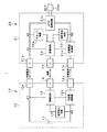
まず、図1に示すような、本発明が適用されたバッテリパック10と、このバッテリパック10を充電する充電器20とからなる充電制御システム1について説明する。
<1. Overall configuration>
First, a
バッテリパック10は、図1に示すように、リチウムイオン二次電池などのバッテリセル11と、バッテリセル11を充電器20などの外部機器と電気的に接続する充放電回路12と、バッテリセル11の温度を検出する温度検出回路13とを備える。また、バッテリパック10は、充電器20などの外部機器と通信を行う通信部14と、バッテリセル11の動作を制御する制御回路15とを備える。
As shown in FIG. 1, the
バッテリセル11は、例えばリチウムイオン二次電池などの充放電可能な電池であって、充放電回路12と接続され、後述する充放電制御部12cによって充電器20などの外部機器と電気的に接続される。
The
充放電回路12は、バッテリセル11を充電器20などの外部機器と電気的に接続する回路であって、具体的には次のような構成からなる。すなわち、充放電回路12は、バッテリセル11の正極端及び負極端と、それぞれ接点P11、P12により電気的に接続されている。また、充放電回路12は、バッテリセル11の正極端と外部機器とを電気的に接続する正極端子12aと、バッテリセル11の負極端と外部機器とを電気的に接続する負極端子12bと、回路内の電気的な接続を制御する充放電制御部12cとからなる。
The charging /
正極端子12aは、バッテリセル11の正極端と外部機器とを電気的に接続する端子であって、図1に示すように後述する充電器20の正極端子21aと接続される。
The positive electrode terminal 12a is a terminal for electrically connecting the positive electrode end of the
負極端子12bは、バッテリセル11の負極端と外部機器とを電気的に接続する端子であって、図1に示すように後述する充電器20の負極端子21bと接続される。
The
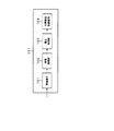
充放電制御部12cは、図2に示すように、充電制御素子121と、放電制御素子122とからなり、回路内の電気的な接続を制御するため、具体的には各素子が次のように接続されることで実現される。
As shown in FIG. 2, the charge /
充電制御素子121は、外部機器からバッテリセル11に充電電流が流れる充電経路の電気的な接続と遮断とを切り換える。例えば、図2に示すように、充電制御素子121は、nチャネルのMOSFETからなり、ゲート端子、ソース端子、ドレイン端子が、それぞれ制御回路15、負極端子12b、放電制御素子122と接続されている。
The
放電制御素子122は、バッテリセル11から外部機器に放電電流が流れる放電経路の電気的な接続と遮断とを切り換える。例えば、放電制御素子122は、nチャネルのMOSFETからなり、ゲート端子、ソース端子、ドレイン端子が、それぞれ制御回路15、バッテリセル11の負極端子、充電制御素子121のドレイン端子と接続されている。
The
このような構成からなる充放電制御部12cでは、制御回路15により、充電制御素子121のゲート電圧が制御されることでドレイン−ソース間が導通することで充電経路が電気的に接続される。ここで、充電経路では、放電制御素子122のドレイン−ソース間を介して充電電流が流れることとなる。また、充放電制御部12cでは、制御回路15により、放電制御素子122のゲート電圧が制御されることでドレイン−ソース間が導通することで放電経路が電気的に接続される。ここで、放電経路では、充電制御素子121のドレイン−ソース間を介して放電電流が流れることとなる。
In the charge /
温度検出回路13は、バッテリセル11等の温度を検出するため、例えば素子の温度変化に応じて抵抗値が変化するサーミスタなどの抵抗素子からなり、図1に示すように制御回路15と接点P12と接続される。温度検出回路13は、バッテリセル11等の温度を検出し、検出結果を電圧に変換して制御回路15に通知する。
The
通信部14は、外部機器と通信を行う。具体的に通信部14は、後述する充電器20の制御回路24と接続され、制御回路15から供給される情報を充電器20に送信したり、充電器20から情報を受信して制御回路15に供給する。
The
制御回路15は、温度検出回路13による検出結果に応じて、充放電回路12及び通信部14の動作を制御する。
The
以上のような構成からなるバッテリパック10に対して充電を行う充電器20は、次のような構成を有している。すなわち、充電器20は、バッテリパック10が備えるバッテリセル11に充電電力を供給する充電回路21と、充電回路21の温度を検出する温度検出回路22と、バッテリと通信を行う通信部23と、充電回路21の充電動作を制御する制御回路24とを備える。また、充電器20には、商用の交流電源であるコンセントと接続されるACコード20aが設けられている。
The
充電回路21は、正極端子21aと、負極端子21bと、ACコード20aにより供給された交流電源電圧を直流電源電圧に変換するAC/DC変換回路21cと、回路内の電流の流れを制御する充電電流制御部21dとからなる。
The charging
正極端子21aは、バッテリパック10の正極端子12aと電気的に接続される端子である。
The positive terminal 21 a is a terminal that is electrically connected to the positive terminal 12 a of the
負極端子21bは、バッテリパック10の負極端子12bと電気的に接続される端子である。
The negative terminal 21 b is a terminal that is electrically connected to the
AC/DC変換回路21cは、ACコード20aにより供給される交流電源電圧を直流電源電圧に変換する回路であって、接点P21、P22を介して正極端子21aと電気的に接続され、接点P23を介して充電電流制御部21dと電気的に接続される。
The AC /
充電電流制御部21dは、回路内の電流の流れを制御するため、例えばnチャネルのMOSFETからなり、ゲート端子、ソース端子、ドレイン端子が、それぞれ制御回路24、接点P23を介してAC/DC変換回路21c、負極端子21bと接続されている。充電電流制御部21dは、制御回路24によりゲート電圧が制御されることでドレイン−ソース間が導通することで充電経路が電気的に接続される。
The charging
温度検出回路22は、充電回路21の温度を検出するため、例えば素子の温度変化に応じて抵抗値が変化するサーミスタなどの抵抗素子からなり、図1に示すように制御回路24と接点P23と接続される。温度検出回路22は、充電回路21の温度を検出し、検出結果を電圧に変換して制御回路24に通知する。
The
通信部23は、バッテリパック10の通信部14と電気的に接続され、制御回路24から供給される情報をバッテリパック10に送信したり、バッテリパック10から情報を受信して制御回路24に供給する。
The
制御回路24は、温度検出回路22による検出結果に応じて、充電回路21及び通信部23の動作を制御する。
The
以上のような構成からなる充電器20と電気的に接続されることで充電されるバッテリパック10は、図3に示すような電気機器30と接続されることで放電動作が行われることとなる。図3は、バッテリパック10と、バッテリパック10からの放電電力の供給により駆動する電気機器30とからなる放電制御システム2の全体構成を示す図である。
The
電気機器30は、バッテリパック10から供給される放電電力によって駆動するビデオカメラなどの携帯型の電気機器であって、図3に示すように、バッテリパック10から供給される放電電力により駆動する負荷回路31と、負荷回路31の温度を検出する温度検出回路32と、バッテリパック10と通信を行う通信部33と、負荷回路31による放電動作を制御する制御回路34とを備える。
The
負荷回路31は、正極端子31aと、負極端子31bと、電源スイッチ31cと、当該電気機器30の主要な機能を実現する駆動部311に直流電圧を供給するDC/DC変換回路31dと、回路内の電流の流れを制御する放電電流制御部31eとからなる。
The
正極端子31aは、バッテリパック10の正極端子12aと電気的に接続される端子である。
The positive terminal 31 a is a terminal that is electrically connected to the positive terminal 12 a of the
負極端子31bは、バッテリパック10の負極端子12bと電気的に接続される端子である。
The
DC/DC変換回路31dは、バッテリパック10から供給された直流電源電圧を昇圧して、昇圧した直流電圧を駆動部311に供給する変換回路であり、接点P31、P32を介して電源スイッチ31cと接続され、接点P33を介して放電電流制御部31eと接続される。
The DC / DC conversion circuit 31d is a conversion circuit that boosts the DC power supply voltage supplied from the
電源スイッチ31cは、一端が正極端子31aと接続され、他端が、接点P31を介してそれぞれDC/DC変換回路31d、制御回路34と接続される。電源スイッチ31cは、例えばユーザからの押圧動作によって、正極端子31aに対して、DC/DC変換回路31dと、制御回路34とをそれぞれ電気的に接続したり遮断したりする。
The power switch 31c has one end connected to the positive terminal 31a and the other end connected to the DC / DC conversion circuit 31d and the
放電電流制御部31eは、回路内の電流の流れを制御するため、例えばnチャネルのMOSFETからなり、ゲート端子、ソース端子、ドレイン端子が、それぞれ制御回路34、負極端子31b、接点P33を介してDC/DC変換回路31dと接続される。放電電流制御部31eは、制御回路34によりゲート電圧が制御されることでドレイン−ソース間が導通することで放電経路が電気的に接続される。
The discharge current control unit 31e is composed of, for example, an n-channel MOSFET in order to control the flow of current in the circuit, and the gate terminal, the source terminal, and the drain terminal are respectively connected via the
温度検出回路32は、負荷回路31の温度を検出するため、例えば素子の温度変化に応じて抵抗値が変化するサーミスタなどの抵抗素子からなり、図3に示すように制御回路34と接点P33と接続される。温度検出回路32は、負荷回路31の温度を検出し、検出結果を電圧に変換して制御回路34に通知する。
In order to detect the temperature of the
通信部33は、バッテリパック10の通信部14と電気的に接続され、制御回路34から供給される情報をバッテリパック10に送信したり、バッテリから情報を受信して制御回路34に供給する。
The
制御回路34は、温度検出回路32による検出結果に応じて、負荷回路31及び通信部33の動作を制御する。
The
次に、電気機器30の駆動部311の具体例を図4に示す。図4は、駆動部311の具体例として、被写体を撮像する撮像装置の構成を示す図である。すなわち、駆動部311は、図4に示すように、撮像素子101と画像処理部102と書込処理部103と不揮発性記録媒体104とからなり、これらの処理部がDC/DC変換回路31dにより供給される直流電圧によって駆動するものである。
Next, a specific example of the
撮像素子101は、被写体を撮像して撮像信号を画像処理部102に供給する。画像処理部102は、撮像素子101により供給される撮像信号に対して、ゲイン補正、ホワイトバランスなどの画像信号処理を施して、書込処理部103に供給する。書込処理部103は、画像処理部102から供給される画像情報を、ハードディスクなどの不揮発性記録媒体104に書き込む処理を行う。
The
<2.温度管理>
以上のような構成からなる充電制御システム1及び放電制御システム2では、次のような処理を行うことによって、システム全体で温度管理をすることで、より確実にバッテリセル11が過剰な発熱が起きないようにする。
<2. Temperature control>
In the
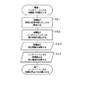
まず、充電器20で充電中にバッテリパック10のバッテリセル11等の温度が所定の温度を超えたときに充電を停止する充電制御システム1に係る動作例について、図5のフローチャートを参照して説明する。
First, referring to the flowchart of FIG. 5, an operation example according to the
まず、本処理の前提として、充電制御システム1では、バッテリパック10と充電器20とが接続されて充電動作を行っているものとする。
First, as a premise of this process, in the charging
ステップS11において、バッテリパック10の温度検出回路13は、バッテリセル11等が所定の温度を超えたことを検出して、この検出結果を電圧に変換して制御回路15に通知する。
In step S11, the
ステップS12において、バッテリパック10の制御回路15は、温度検出回路13により検出されたバッテリセル11等の温度情報を送信するように、通信部14を制御する。
In step S <b> 12, the
ステップS13において、充電器20の通信部23は、バッテリパック10から送信されてくるバッテリセル11等の温度情報を受信して、制御回路24に通知する。
In step S <b> 13, the
ステップS14において、充電器20の制御回路24は、通信部23により受信したバッテリセル11等の温度情報に応じて、バッテリパック10との電気的な接続を遮断して充電動作を停止するように充電回路21の充電電流制御部21dを制御する。
In step S14, the
ステップS15において、充電器20の制御回路24は、充電回路21の充電動作が停止したことを示す停止情報をバッテリパック10に送信するように通信部23を制御する。
In step S <b> 15, the
ステップS16において、バッテリパック10では、通信部14により充電器20から送信されてくる停止情報を受信すると、制御回路15が、充電器20との電気的な接続を遮断するように充放電回路12の充放電制御部12cを制御する。すなわち、制御回路15は、充放電制御部12cの充電制御素子121が電気的に遮断するようにオフ状態にする。
In step S <b> 16, when the
以上のようにして、充電制御システム1では、バッテリセル11等の温度が所定の温度を超えたことが通知された充電器20側で充電動作を停止して、充電器20側で充電動作を停止した後にバッテリパック10が充放電回路12の充電動作を停止する。このように、充電制御システム1では、バッテリと充電器20とがそれぞれ温度検出を行い、一方の検出結果を他方に送信することにより温度情報を共有して充放電経路の電気的な接続を遮断するので、より確実にバッテリセル11等が過剰な発熱が起きないようにして、充電動作を制御することができる。より具体的には、バッテリ側で充電動作を停止しても、充電器側が充電可能状態が維持されることで、その後バッテリセルの温度が低下することで充電動作が開始されてバッテリセル等の温度が再び発熱してしまうことを防止することができる。
As described above, the charging
次に、充電器20で充電中に充電回路21の温度が所定の温度を超えたときに充電を停止する充電制御システム1に係る動作例について、図6のフローチャートを参照して説明する。
Next, an operation example according to the charging
まず、本処理の前提として、充電制御システム1では、バッテリパック10と充電器20とが接続され充電動作を行っているものとする。
First, as a premise of this process, in the
ステップS21において、充電器20の温度検出回路22は、充電回路21の温度が所定の温度を超えたことを検出して、この検出結果を電圧に変換して制御回路24に通知する。
In step S <b> 21, the
ステップS22において、充電器20の制御回路24は、温度検出回路22による検出結果に応じて、バッテリパック10との電気的な接続を遮断して充電動作を停止するように充電回路21の充電電流制御部21dを制御する。すなわち、制御回路24は、充電電流制御部21dが充電経路を電気的に遮断するようにオフ状態にする。
In step S22, the
ステップS23において、充電器20の制御回路24は、充電回路21の充電動作が停止したことを示す停止情報をバッテリパック10に送信するように通信部23を制御する。
In step S <b> 23, the
ステップS24において、バッテリパック10では、通信部14により充電器20から送信されてくる停止情報を受信すると、制御回路15が、充電器20との電気的な接続を遮断するように充放電回路12の充放電制御部12cを制御する。すなわち、制御回路15は、充放電制御部12cの充電制御素子121が電気的に遮断するようにオフ状態にする。
In step S <b> 24, when the
以上のようにして、充電制御システム1では、充電回路21の温度が所定の温度を超えたことに応じて充電器20側で充電動作を停止して、充電器20側で充電動作を停止した後にバッテリパック10が充放電回路12の充電動作を停止する。このように、充電制御システム1では、バッテリと充電器20とがそれぞれ温度検出を行い、一方の検出結果を他方に送信することにより温度情報を共有して充放電経路の電気的な接続を遮断するので、より確実にバッテリセル11等が過剰な発熱が起きないようにして、充電動作を行うことができる。より具体的には、充電器側で充電動作を停止しても、バッテリ側が充電可能状態が維持されることで、その後充電器の温度が低下することで充電動作が開始されて充電器の温度が再び発熱してしまうことを防止することができる。
As described above, in the charging
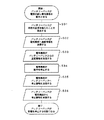
次に、電気機器30と接続されたバッテリパック10が放電動作中に、バッテリセル11等の温度が所定の温度を超えたときに放電動作を停止する放電制御システム2に係る動作例について、図7のフローチャートを参照して説明する。
Next, an operation example according to the discharge control system 2 that stops the discharge operation when the temperature of the
まず、本処理の前提として、放電制御システム2では、バッテリパック10と電気機器30とが接続されて放電動作を行っているものとする。
First, as a premise of this process, in the discharge control system 2, it is assumed that the
ステップS31において、バッテリパック10の温度検出回路13は、バッテリセル11等の温度が所定の温度を超えたことを検出して、この検出結果を電圧に変換して制御回路15に通知する。
In step S31, the
ステップS32において、バッテリパック10の制御回路15は、温度検出回路13により検出されたバッテリセル11等の温度情報を送信するように、通信部14を制御する。
In step S <b> 32, the
ステップS33において、電気機器30の通信部33は、バッテリパック10から送信されてくるバッテリセル11等の温度情報を受信して、制御回路34に通知する。
In step S <b> 33, the
ステップS34において、電気機器30の制御回路34は、通信部33により受信したバッテリセル11等の温度情報に応じて、バッテリパック10との電気的な接続を遮断して放電動作を停止するように負荷回路31の放電電流制御部31eを制御する。
In step S <b> 34, the
具体的に、制御回路34は、駆動部311において書込処理部103が書込動作中のときは書込動作が終了してから、放電電流制御部31eによる電気的な接続を遮断するように制御する。このようにすることで、電気機器30は、不揮発性記録媒体104への書込動作が完了せずに電源がオフになってしまうことを防止することができる。
Specifically, when the
また、電気機器30では、この駆動部311の終了動作を、例えば当該機器に設けられたディスプレイやスピーカにより、ユーザに告知するようにしてもよく、このようにすることで、ユーザが意図しない動作の停止を事前に告知することができる。
Further, in the
また、電気機器30は、バッテリパック10からバッテリセルの温度情報を受信してから所定の時間内に書込処理を停止できない場合には、書込処理の完了を待つことなく書込処理部103の動作を停止してもよい。このようにすることで、バッテリセル11等が高温状態に長時間維持されることを防止することができる。
In addition, when the
また、放電制御システム2においては、バッテリセル11等の温度が第1の温度を超えたときと、この第1の温度より高い第2の温度を超えたときにそれぞれバッテリパック10から電気機器30側にバッテリセル11等の温度情報を通知するようにしてもよい。そして電気機器30では、第1の温度を示すバッテリセル等の温度情報を受けたときは、書込処理を停止してから放電動作を停止するようにし、第2の温度を示すバッテリセル等の温度情報を受けたときは、書込処理を停止することなく放電動作を停止する。このようにして温度情報に応じて段階的に制御することで、バッテリセル11等が高温状態に長時間維持されることを防止することができる。
Further, in the discharge control system 2, when the temperature of the
ステップS35において、電気機器30の制御回路34は、負荷回路31の放電動作が停止したことを示す停止情報をバッテリパック10に送信するように通信部33を制御する。
In step S <b> 35, the
ステップS36において、バッテリパック10では、通信部14により電気機器30から送信されてくる停止情報を受信すると、制御回路15が、電気機器30との電気的な接続を遮断するように充放電回路12の充放電制御部12cを制御する。すなわち、制御回路15は、充放電制御部12cの放電制御素子122が電気的に遮断するようにオフ状態にする。
In step S <b> 36, when the
以上のようにして、放電制御システム2では、バッテリセル11等の温度が所定の温度を超えたことが通知された電気機器30側で放電動作を停止して、電気機器30側で放電動作を停止した後にバッテリパック10が充放電回路12の放電動作を停止する。このように、放電制御システム2では、バッテリパック10との間で放電動作を行うシステム全体で温度管理をすることで、より確実にバッテリセル11が過剰な発熱が起きないようにして、放電動作を行うことができる。より具体的には、バッテリ側で放電動作を停止しても、電気機器側が放電可能状態が維持されることで、その後バッテリセル等の温度が低下することで放電動作が開始されてバッテリセル等の温度が再び発熱してしまうことを防止することができる。
As described above, in the discharge control system 2, the discharge operation is stopped on the
次に、電気機器30と接続されたバッテリパック10が放電動作中に、電気機器30の負荷回路31の温度が所定の温度を超えたときに放電を停止する放電制御システム2に係る動作例について、図8のフローチャートを参照して説明する。
Next, an operation example according to the discharge control system 2 that stops the discharge when the temperature of the
まず、本処理の前提として、放電制御システム2では、バッテリパック10と電気機器30とが接続され放電動作を行っているものとする。
First, as a premise of this process, in the discharge control system 2, it is assumed that the
ステップS41において、電気機器30の温度検出回路32は、負荷回路31の温度が所定の温度を超えたことを検出して、この検出結果を電圧に変換して制御回路34に通知する。
In step S41, the temperature detection circuit 32 of the
ステップS42において、電気機器30の制御回路34は、温度検出回路32による検出結果に応じて、バッテリパック10との電気的な接続を遮断して放電動作を停止するように負荷回路31の放電電流制御部31eを制御する。
In step S <b> 42, the
具体的に、制御回路34は、駆動部311において書込処理部103が書込動作中のときは書込動作が終了してから、放電電流制御部31eによる電気的な接続を遮断するように制御する。このようにすることで、電気機器30は、不揮発性記録媒体104への書込動作が完了せずに電源がオフ状態になってしまうことを防止することができる。
Specifically, when the
また、電気機器30では、この駆動部311の終了動作を、例えば当該機器に設けられたディスプレイやスピーカにより、ユーザに告知するようにしてもよく、このようにすることで、ユーザが意図しない動作を事前に告知することができる。
Further, in the
また、電気機器30は、所定の時間内に書込処理を停止できない場合には、書込処理の完了を待つことなく書込処理部103の書込動作を停止してもよい。このようにすることで、負荷回路31が高温状態に長時間維持されることを防止することができる。
In addition, when it is not possible to stop the writing process within a predetermined time, the
また、電気機器30は、負荷回路31の温度が第1の温度を超えたことと、この第1の温度より高い第2の温度を超えたこととをそれぞれ温度検出回路33により検出して、制御回路34に通知するようにしてもよい。電気機器20では、第1の温度を示す負荷回路の温度情報を受けたときは、書込処理を停止してから放電動作を停止するようにし、第2の温度を示す負荷回路の温度情報を受けたときは、書込処理を停止することなく放電動作を停止する。このように温度情報に応じて段階的に制御することで、負荷回路31が高温状態に長時間維持されることを防止することができる。
In addition, the
ステップS43において、電気機器30の制御回路34は、負荷回路31による放電動作が停止したことを示す停止情報をバッテリパック10に送信するように通信部33を制御する。
In step S <b> 43, the
ステップS44において、バッテリパック10では、通信部33により電気機器30から送信されてくる停止情報を受信すると、制御回路15が、電気機器30との電気的な接続を遮断するように充放電回路12の充放電制御部12cを制御する。すなわち、制御回路15は、充放電制御部12cの放電制御素子122が電気的に遮断するようにオフ状態にする。
In step S <b> 44, when the
以上のようにして、放電制御システム2では、負荷回路31の温度が所定の温度を超えたことに応じて電気機器30側で放電動作を停止して、電気機器30側で放電動作を停止した後にバッテリパック10が充放電回路12の放電動作を停止する。このように、放電制御システム2では、バッテリパック10との間で充電又は放電動作を行うシステム全体で温度管理をすることで、より確実に負荷回路31が過剰な発熱が起きないようにして、放電動作を行うことができる。より具体的には、電気機器側で放電動作を停止しても、バッテリ側が放電可能状態が維持されることで、その後電気機器の温度が低下することで放電動作が開始されて電気機器の温度が再び発熱してしまうことを防止することができる。
As described above, in the discharge control system 2, the discharge operation is stopped on the
<3.復帰処理>
上述した停止動作によって、バッテリパック10が充電制御素子121をオフ状態にして充電経路を電気的に遮断している状態を維持している場合、バッテリセル11等の温度が正常範囲に戻っても充電経路が電気的に遮断されるため、充電動作を行うことができない。そこで、バッテリパック10は、次の図9に示すような処理を行うことで充電禁止状態から充電可能状態に復帰する。
<3. Return processing>
Even when the temperature of the
まず、本処理の前提として、バッテリパック10は、充電禁止状態、すなわち、充放電回路12の充電経路を電気的に遮断しているものとする。
First, as a premise of this processing, it is assumed that the
ステップS51において、バッテリパック10は、バッテリセル11の放電電力により駆動する電気機器30と接続される。
In step S <b> 51, the
ステップS52において、バッテリパック10と接続された電気機器30は、負荷回路31の電源スイッチ31cがオン状態にされることで、放電動作を開始する。
In step S <b> 52, the
ステップS53において、バッテリパック10は、充放電回路12においてバッテリセル11から電気機器30に放電電流が流れると、充電制御素子121により、この充電経路を電気的に接続するように切り換える。ここで、充電制御素子121は、充放電回路12において放電経路に電流が流れるのをトリガーとして、又は、制御回路15による制御によって充電経路を電気的に接続するように切り換える。
In step S <b> 53, when a discharge current flows from the
以上のようにして、バッテリパック10は、放電動作に応じて、充電経路を充電禁止状態から充電可能状態に復帰する。すなわち、バッテリパック10は、バッテリセル11等の温度が下がったときと別の条件で復帰処理を行うことにより、バッテリセル11が過剰に発熱するのを防止しつつ、充電経路を充電禁止状態から充電可能状態に復帰することができる。
As described above, the
また、バッテリパック10が放電制御素子122をオフ状態にして放電経路を電気的に遮断している状態を維持している場合、バッテリセル11等の温度が正常範囲に戻っても放電経路が電気的に遮断されるため、放電動作を行うことができない。そこで、バッテリパック10は、次の図10に示すような処理を行うことで放電禁止状態から放電可能状態に復帰する。
Further, when the
まず、本処理の前提として、バッテリパック10は、放電禁止状態、すなわち、充放電回路12の放電経路を電気的に遮断しているものとする。
First, as a premise of this process, it is assumed that the
ステップS61において、バッテリパック10は、バッテリセル11に充電電流を供給する充電器20と接続される。
In step S <b> 61, the
ステップS62において、バッテリパック10と接続された充電器20は、充電回路21の充電動作を開始する。
In step S <b> 62, the
ステップS63において、バッテリパック10は、充放電回路12においてバッテリセル11に充電器20から供給される充電電流が流れると、放電制御素子122により、この放電経路を電気的に接続するように切り換える。ここで、放電制御素子122は、充放電回路12において放電経路に電流が流れるのをトリガーとして、又は、制御回路15による制御によって、放電経路を電気的に接続するように切り換える。
In step S <b> 63, when the charging current supplied from the
以上のようにして、バッテリパック10は、充電動作に応じて、放電経路を放電禁止状態から放電可能状態に復帰する。すなわち、バッテリパック10は、バッテリセル11の温度が下がったときと別の条件で復帰処理を行うことにより、バッテリセル11が過剰に発熱するのを防止しつつ、放電経路を放電禁止状態から放電可能状態に復帰することができる。
As described above, the
バッテリパック10の充電動作時において、充電器自体の異常発熱を検出して充電動作を停止した充電器は、この停止状態を維持しているため、充電回路21の温度が正常範囲に戻っても、この停止状態から復帰しない。そこで、充電器20は、次の図11に示すような処理を行うことで充電禁止状態から充電可能状態に復帰する。
During the charging operation of the
まず、本処理の前提として、充電器20は、充電禁止状態、すなわち、充電回路21の充電経路を電気的に遮断しているものとする。
First, as a premise of this process, it is assumed that the
ステップS71において、充電器20は、ACコード20aからの商用電源の供給が遮断される。
In step S71, the
ステップS72において、充電器20は、充電回路21の温度が正常範囲に戻る。
In step S72, the
ステップS73において、充電器20は、ACコード20aからの商用電源の供給を受けると、電流の流れ等をリセット回路24aが検出して、この検出結果に応じて制御回路24が充電電流制御部21dを制御して充電可能状態に復帰する。
In step S73, when the
以上のようにして、充電器20は、充電回路21の温度が正常範囲に戻り、ACコード20aがコンセントに再投入されて商用電源の供給を受けると、充電禁止状態から充電可能状態に復帰する。このようにして、充電器20は、充電回路21が過剰に発熱するのを防止しつつ、充電禁止状態から充電可能状態に復帰することができる。
As described above, when the temperature of the charging
また、バッテリパック10の放電動作時において、電気機器自体の異常発熱を検出して放電動作を停止した電気機器30は、この停止状態を維持しているため、負荷回路31の温度が正常範囲に戻っても、この停止状態から復帰しない。そこで、電気機器30は、図12に示すような処理を行うことで放電禁止状態から放電可能状態に復帰する。
Further, during the discharging operation of the
まず、本処理の前提として、電気機器30は、放電禁止状態、すなわち、負荷回路31の放電経路を電気的に遮断しているものとする。
First, as a premise of this process, it is assumed that the
ステップS81において、電気機器30は、電源スイッチ31cが遮断される。
In step S81, the
ステップS82において、電気機器30は、負荷回路31の温度が正常範囲に戻る。
In step S82, the
ステップS83において、電気機器30は、電源スイッチ31cがオン状態になると、電流の流れ等をリセット回路34aが検出して、この動作に応じて制御回路34が放電電流制御部31eを制御して放電可能状態に復帰する。
In step S83, when the power switch 31c is turned on in the
以上のようにして、電気機器30は、負荷回路31の温度が正常範囲に戻り、電源スイッチ31cが再投入されると、放電禁止状態から放電可能状態に復帰する。このようにして、電気機器30は、負荷回路31が過剰に発熱するのを防止しつつ、放電禁止状態から放電可能状態に復帰することができる。
As described above, when the temperature of the
1 充電制御システム、2 放電制御システム、10 バッテリパック、11 バッテリセル、20 電気機器、12 充放電回路、12a、21a、31a 正極端子、12b、21b、31b 負極端子、12c 充放電制御部、121 充電制御素子、122 放電制御素子、13、22、32 温度検出回路、14、23、33 通信部、15、24、34 制御回路、20 充電器、20a ACコード、21 充電回路、21c AC/DC変換回路、21d 充電電流制御部、24aリセット回路、30 電気機器、31 負荷回路、31c 電源スイッチ、31d DC/DC変換回路、31e 放電電流制御部、311 駆動部、101 撮像素子、102 画像処理部、103 書込処理部、104 不揮発性記録媒体
DESCRIPTION OF
Claims (10)
上記バッテリセルを外部機器と電気的に接続する充放電回路と、
上記バッテリセルの温度を検出する温度検出部と、
上記外部機器と通信を行う通信部と、
上記温度検出部により検出されるバッテリセルの温度が所定の温度を超えたとき、このバッテリセルの温度情報を送信するように上記通信部を制御し、上記外部機器から動作停止を示す停止情報が送信されてきたとき、この外部機器との電気的な接続を遮断するように上記充放電回路を制御する制御部とを備えるバッテリ。 A battery cell;
A charge / discharge circuit for electrically connecting the battery cell to an external device;
A temperature detector for detecting the temperature of the battery cell;
A communication unit for communicating with the external device;
When the temperature of the battery cell detected by the temperature detection unit exceeds a predetermined temperature, the communication unit is controlled to transmit the temperature information of the battery cell, and stop information indicating operation stop is received from the external device. A battery comprising: a control unit that controls the charge / discharge circuit so as to cut off an electrical connection with the external device when transmitted.
上記充電制御素子は、上記充電経路を電気的に遮断しているとき、上記充放電回路において上記バッテリセルから上記外部機器に放電電流が流れると、この充電経路を電気的に接続するように切り換える請求項1記載のバッテリ。 The charge / discharge circuit is connected with a charge control element that is switched between electrical connection and disconnection of a charge path through which a charge current flows from the external device to the battery cell by the control unit,
The charge control element switches the charge path to be electrically connected when a discharge current flows from the battery cell to the external device in the charge / discharge circuit when the charge path is electrically cut off. The battery according to claim 1.
上記放電制御素子は、上記放電経路を電気的に遮断しているとき、上記充放電回路において上記外部機器から上記バッテリセルに充電電流が流れると、この放電経路を電気的に接続するように切り換える請求項1記載のバッテリ。 The charge / discharge circuit is connected with a discharge control element that is switched between electrical connection and interruption of a discharge path through which a discharge current flows from the battery cell to the external device by the control unit,
When the discharge control element electrically cuts off the discharge path, when a charging current flows from the external device to the battery cell in the charge / discharge circuit, the discharge control element is switched to electrically connect the discharge path. The battery according to claim 1.
上記検出ステップにより検出されるバッテリセルの温度が所定の温度を超えたとき、このバッテリセルの温度情報を、このバッテリセルと充放電回路を介して電気的に接続される外部機器に送信する送信ステップと、
上記外部機器から動作停止を示す停止情報が送信されてきたとき、この外部機器との電気的な接続を遮断するように上記充放電回路を制御する遮断ステップとを有するバッテリの制御方法。 A detecting step for detecting the temperature of the battery cell;
When the temperature of the battery cell detected by the detection step exceeds a predetermined temperature, the battery cell temperature information is transmitted to an external device electrically connected to the battery cell via the charge / discharge circuit. Steps,
A battery control method comprising: a shut-off step for controlling the charge / discharge circuit so that electrical connection with the external device is shut off when stop information indicating operation stop is transmitted from the external device.
上記充電回路の温度を検出する温度検出部と、
上記バッテリと通信を行う通信部と、
上記バッテリセルが所定の温度を超えたことを示す温度情報が上記通信部に送信されてきたとき、又は、上記温度検出部により検出される充電回路の温度が所定の温度を超えたとき、上記バッテリとの電気的な接続を遮断するように上記充電回路を制御した後、この充電回路の充電動作が停止したことを示す停止情報を送信するように上記通信部を制御する制御部とを備える充電器。 A charging circuit for supplying a charging current to a battery cell included in the battery;
A temperature detector for detecting the temperature of the charging circuit;
A communication unit for communicating with the battery;
When temperature information indicating that the battery cell has exceeded a predetermined temperature has been transmitted to the communication unit, or when the temperature of the charging circuit detected by the temperature detection unit has exceeded a predetermined temperature, A control unit that controls the communication unit so as to transmit stop information indicating that the charging operation of the charging circuit is stopped after controlling the charging circuit so as to cut off the electrical connection with the battery; Charger.
上記負荷回路の温度を検出する温度検出部と、
上記バッテリと通信を行う通信部と、
上記バッテリセルが所定の温度を超えたことを示す温度情報が上記通信部に送信されてきたとき、又は、上記温度検出部により検出される負荷回路の温度が所定の温度を超えたとき、上記バッテリとの電気的な接続を遮断するように上記負荷回路を制御した後、この負荷回路による放電動作が停止したことを示す停止情報を送信するように上記通信部を制御する制御部とを備える電気機器。 A load circuit driven by discharge power supplied from the battery;
A temperature detector for detecting the temperature of the load circuit;
A communication unit for communicating with the battery;
When temperature information indicating that the battery cell has exceeded a predetermined temperature has been transmitted to the communication unit, or when the temperature of the load circuit detected by the temperature detection unit has exceeded a predetermined temperature, A control unit that controls the communication unit so as to transmit stop information indicating that the discharge operation by the load circuit has stopped after controlling the load circuit so as to cut off the electrical connection with the battery; Electrical equipment.
上記制御部は、上記温度検出部により検出される負荷回路の温度が第1の温度を超えたとき、上記書込処理部に不揮発性記憶媒体への情報の書込処理を終了させて、上記バッテリとの電気的な接続を遮断するように上記負荷回路を制御した後、この負荷回路による放電動作が停止したことを示す停止情報を送信するように上記通信部を制御する請求項6記載の電気機器。 The load circuit includes a write processing unit that writes information to a nonvolatile storage medium,
The controller, when the temperature of the load circuit detected by the temperature detector exceeds a first temperature, causes the write processor to finish writing information to the nonvolatile storage medium, and The control unit according to claim 6, wherein the communication unit is controlled to transmit stop information indicating that the discharging operation by the load circuit is stopped after controlling the load circuit so as to cut off the electrical connection with the battery. Electrical equipment.
上記バッテリの充電を行う充電器とを備え、
上記バッテリは、バッテリセルと、このバッテリセルと上記充電器とを電気的に接続する充電回路と、このバッテリセルの温度を検出する温度検出部と、この充電器と通信を行う通信部と、この温度検出部により検出されるバッテリセルの温度が所定の温度を超えたとき、このバッテリセルの温度情報を送信するようにこの通信部を制御し、この充電器から充電動作の停止を示す停止情報が送信されてきたとき、この充電器との電気的な接続を遮断するようにこの充電回路を制御する制御部とを有し、
上記充電器は、上記バッテリに充電電流を供給する充電回路と、この充電回路の温度を検出する温度検出部と、このバッテリと通信を行う通信部と、このバッテリのバッテリセルが所定の温度を超えたことを示す温度情報がこの通信部に送信されてきたとき、又は、この温度検出部により検出される充電回路の温度が所定の温度を超えたとき、このバッテリとの電気的な接続を遮断するようにこの充電回路を制御した後、上記停止情報を送信するようにこの通信部を制御する制御部とを有する充電制御システム。 Battery,
A charger for charging the battery,
The battery includes a battery cell, a charging circuit that electrically connects the battery cell and the charger, a temperature detection unit that detects the temperature of the battery cell, a communication unit that communicates with the charger, When the temperature of the battery cell detected by the temperature detection unit exceeds a predetermined temperature, the communication unit is controlled to transmit temperature information of the battery cell, and a stop indicating that the charging operation is stopped from the charger A control unit that controls the charging circuit so as to cut off the electrical connection with the charger when information is transmitted;
The charger includes a charging circuit that supplies a charging current to the battery, a temperature detection unit that detects a temperature of the charging circuit, a communication unit that communicates with the battery, and a battery cell of the battery has a predetermined temperature. When the temperature information indicating that the temperature has exceeded is transmitted to the communication unit, or when the temperature of the charging circuit detected by the temperature detection unit exceeds a predetermined temperature, the electrical connection with the battery is established. A charging control system comprising: a control unit that controls the communication unit so as to transmit the stop information after controlling the charging circuit to shut off.
上記バッテリから放電電流が供給される電気機器とを備え、
上記バッテリは、バッテリセルと、このバッテリセルと上記電気機器とを電気的に接続する放電回路と、このバッテリセルの温度を検出する温度検出部と、この電気機器と通信を行う通信部と、この温度検出部により検出されるバッテリセルの温度が所定の温度を超えたとき、このバッテリセルの温度情報を送信するようにこの通信部を制御し、この電気機器から放電動作の停止を示す停止情報が送信されてきたとき、この電気機器との電気的な接続を遮断するようにこの放電回路を制御する制御部とを有し、
上記電気機器は、上記バッテリから供給される放電電力により駆動する負荷回路と、この負荷回路の温度を検出する温度検出部と、このバッテリと通信を行う通信部と、このバッテリのバッテリセルが所定の温度を超えたことを示す温度情報がこの通信部に送信されてきたとき、又は、この温度検出部により検出される負荷回路の温度が所定の温度を超えたとき、このバッテリとの電気的な接続を遮断するようにこの負荷回路を制御した後、上記停止情報を送信するようにこの通信部を制御する制御部とを有する放電制御システム。 Battery,
An electrical device to which discharge current is supplied from the battery,
The battery includes a battery cell, a discharge circuit that electrically connects the battery cell and the electrical device, a temperature detection unit that detects the temperature of the battery cell, a communication unit that communicates with the electrical device, When the temperature of the battery cell detected by the temperature detection unit exceeds a predetermined temperature, the communication unit is controlled to transmit the temperature information of the battery cell, and a stop indicating that the discharge operation is stopped from the electric device A control unit that controls the discharge circuit to cut off the electrical connection with the electrical device when information is transmitted;
The electrical device includes a load circuit that is driven by discharge power supplied from the battery, a temperature detection unit that detects a temperature of the load circuit, a communication unit that communicates with the battery, and a battery cell of the battery. When temperature information indicating that the temperature of the load circuit has been transmitted to the communication unit, or when the temperature of the load circuit detected by the temperature detection unit exceeds a predetermined temperature, And a control unit that controls the communication unit so as to transmit the stop information after controlling the load circuit so as to cut off the connection.
Priority Applications (1)
| Application Number | Priority Date | Filing Date | Title |
|---|---|---|---|
| JP2008248700A JP5422955B2 (en) | 2008-09-26 | 2008-09-26 | Battery, battery control method, charger, electric device, charge control system, and discharge control system |
Applications Claiming Priority (1)
| Application Number | Priority Date | Filing Date | Title |
|---|---|---|---|
| JP2008248700A JP5422955B2 (en) | 2008-09-26 | 2008-09-26 | Battery, battery control method, charger, electric device, charge control system, and discharge control system |
Publications (2)
| Publication Number | Publication Date |
|---|---|
| JP2010081757A true JP2010081757A (en) | 2010-04-08 |
| JP5422955B2 JP5422955B2 (en) | 2014-02-19 |
Family
ID=42211542
Family Applications (1)
| Application Number | Title | Priority Date | Filing Date |
|---|---|---|---|
| JP2008248700A Expired - Fee Related JP5422955B2 (en) | 2008-09-26 | 2008-09-26 | Battery, battery control method, charger, electric device, charge control system, and discharge control system |
Country Status (1)
| Country | Link |
|---|---|
| JP (1) | JP5422955B2 (en) |
Cited By (6)
| Publication number | Priority date | Publication date | Assignee | Title |
|---|---|---|---|---|
| US20150362383A1 (en) * | 2012-04-26 | 2015-12-17 | Toyota Jidosha Kabushiki Kaisha | Gas filling system and vehicle |
| KR101663579B1 (en) * | 2015-06-23 | 2016-10-07 | 주식회사 비엠일렉텍 | Battery monitoring device and battery monitoring system using the same |
| KR20160133427A (en) * | 2014-01-28 | 2016-11-22 | 광동 오포 모바일 텔레커뮤니케이션즈 코포레이션 리미티드 | Quick-charging control method and system |
| JP2020162411A (en) * | 2011-04-28 | 2020-10-01 | ゾール サーキュレイション インコーポレイテッドZOLL Circulation,Inc. | Battery management system for control of lithium power cells |
| WO2022229149A1 (en) | 2021-04-30 | 2022-11-03 | Robert Bosch Gmbh | Method for controlling a device, and circuit device |
| JP7323800B2 (en) | 2019-10-18 | 2023-08-09 | ミツミ電機株式会社 | Secondary battery protection circuit, secondary battery protection device, battery pack and temperature detection circuit |
Citations (4)
| Publication number | Priority date | Publication date | Assignee | Title |
|---|---|---|---|---|
| JP2003174720A (en) * | 2001-09-28 | 2003-06-20 | Mitsumi Electric Co Ltd | Secondary battery protective circuit and protective circuit ic |
| JP2007018761A (en) * | 2005-07-05 | 2007-01-25 | Ricoh Co Ltd | Charging system device of secondary battery |
| JP2007115472A (en) * | 2005-10-19 | 2007-05-10 | Matsushita Electric Ind Co Ltd | Battery pack, battery charger, charging system, and method of detecting abnormal charging |
| JP2007141572A (en) * | 2005-11-16 | 2007-06-07 | Matsushita Electric Ind Co Ltd | Battery pack |
-
2008
- 2008-09-26 JP JP2008248700A patent/JP5422955B2/en not_active Expired - Fee Related
Patent Citations (4)
| Publication number | Priority date | Publication date | Assignee | Title |
|---|---|---|---|---|
| JP2003174720A (en) * | 2001-09-28 | 2003-06-20 | Mitsumi Electric Co Ltd | Secondary battery protective circuit and protective circuit ic |
| JP2007018761A (en) * | 2005-07-05 | 2007-01-25 | Ricoh Co Ltd | Charging system device of secondary battery |
| JP2007115472A (en) * | 2005-10-19 | 2007-05-10 | Matsushita Electric Ind Co Ltd | Battery pack, battery charger, charging system, and method of detecting abnormal charging |
| JP2007141572A (en) * | 2005-11-16 | 2007-06-07 | Matsushita Electric Ind Co Ltd | Battery pack |
Cited By (12)
| Publication number | Priority date | Publication date | Assignee | Title |
|---|---|---|---|---|
| JP2020162411A (en) * | 2011-04-28 | 2020-10-01 | ゾール サーキュレイション インコーポレイテッドZOLL Circulation,Inc. | Battery management system for control of lithium power cells |
| US20150362383A1 (en) * | 2012-04-26 | 2015-12-17 | Toyota Jidosha Kabushiki Kaisha | Gas filling system and vehicle |
| US10371587B2 (en) * | 2012-04-26 | 2019-08-06 | Toyota Jidosha Kabushiki Kaisha | Gas filling system and vehicle |
| KR20160133427A (en) * | 2014-01-28 | 2016-11-22 | 광동 오포 모바일 텔레커뮤니케이션즈 코포레이션 리미티드 | Quick-charging control method and system |
| JP2017509294A (en) * | 2014-01-28 | 2017-03-30 | グァンドン オッポ モバイル テレコミュニケーションズ コーポレーション リミテッド | Fast charge control method and system |
| US10110028B2 (en) | 2014-01-28 | 2018-10-23 | Guangdong Oppo Mobile Telecommunications Corp., Ltd. | Quick-charging control method and system |
| KR102093676B1 (en) * | 2014-01-28 | 2020-03-27 | 광동 오포 모바일 텔레커뮤니케이션즈 코포레이션 리미티드 | Quick-charging control method and system |
| US10714950B2 (en) | 2014-01-28 | 2020-07-14 | Guangdong Oppo Mobile Telecommunications Corp., Ltd. | Charging control method and charging device |
| KR101663579B1 (en) * | 2015-06-23 | 2016-10-07 | 주식회사 비엠일렉텍 | Battery monitoring device and battery monitoring system using the same |
| JP7323800B2 (en) | 2019-10-18 | 2023-08-09 | ミツミ電機株式会社 | Secondary battery protection circuit, secondary battery protection device, battery pack and temperature detection circuit |
| WO2022229149A1 (en) | 2021-04-30 | 2022-11-03 | Robert Bosch Gmbh | Method for controlling a device, and circuit device |
| DE102021204358A1 (en) | 2021-04-30 | 2022-11-03 | Robert Bosch Gesellschaft mit beschränkter Haftung | Method of controlling a device and circuit device |
Also Published As
| Publication number | Publication date |
|---|---|
| JP5422955B2 (en) | 2014-02-19 |
Similar Documents
| Publication | Publication Date | Title |
|---|---|---|
| CN107894567B (en) | Battery pack and detection system and detection method for interface state of battery pack | |
| US9564769B2 (en) | Wireless communication controlled battery charging station | |
| JP3749538B2 (en) | Battery unit and device using battery unit | |
| US8143862B2 (en) | Circuits and methods for battery charging | |
| US8953293B2 (en) | Battery protection circuit | |
| JP5422955B2 (en) | Battery, battery control method, charger, electric device, charge control system, and discharge control system | |
| US8687338B2 (en) | Systems and methods for enhanced protection systems for storage batteries | |
| WO2018133537A1 (en) | Electronic device and electronic device-based charging control method | |
| US9118198B2 (en) | Balancing of battery cells connected in parallel | |
| KR102390394B1 (en) | Apparatus and method for controlling main battery and sub battery | |
| RU2012149454A (en) | POWER BATTERY BLOCK, CONTROL DIAGRAM AND PROGRAM | |
| TW200937800A (en) | Charging apparatus and charging method | |
| CN107276145B (en) | Electronic system and charging method | |
| US20150061549A1 (en) | Battery pack, power tool and battery charger | |
| JP2011187227A (en) | Battery pack, electronic equipment, equipment system, control method for battery pack cooling unit, and program | |
| JP2010233358A (en) | Battery protection circuit, battery protection method, power supply unit, and program | |
| KR20120036046A (en) | Apparatus of charging a battery for a electronic device and the controlling method thereof | |
| JP2008236930A (en) | Charging device of secondary battery | |
| JP2008125199A (en) | Control method for battery pack | |
| JP3981893B2 (en) | Battery pack, charger, charging system, and charging method | |
| JP4313809B2 (en) | Rechargeable battery pack system and battery pack charge control method | |
| JP5203270B2 (en) | Secondary battery capacity test system and secondary battery capacity test method | |
| CN103124097A (en) | Intelligent lithium ion charger | |
| KR101649132B1 (en) | Power storage system and driving method thereof | |
| CN107887935A (en) | Battery pack |
Legal Events
| Date | Code | Title | Description |
|---|---|---|---|
| A621 | Written request for application examination |
Free format text: JAPANESE INTERMEDIATE CODE: A621 Effective date: 20110906 |
|
| A977 | Report on retrieval |
Free format text: JAPANESE INTERMEDIATE CODE: A971007 Effective date: 20130425 |
|
| A131 | Notification of reasons for refusal |
Free format text: JAPANESE INTERMEDIATE CODE: A131 Effective date: 20130507 |
|
| A521 | Written amendment |
Free format text: JAPANESE INTERMEDIATE CODE: A523 Effective date: 20130625 |
|
| A131 | Notification of reasons for refusal |
Free format text: JAPANESE INTERMEDIATE CODE: A131 Effective date: 20130723 |
|
| A521 | Written amendment |
Free format text: JAPANESE INTERMEDIATE CODE: A523 Effective date: 20130917 |
|
| TRDD | Decision of grant or rejection written | ||
| A01 | Written decision to grant a patent or to grant a registration (utility model) |
Free format text: JAPANESE INTERMEDIATE CODE: A01 Effective date: 20131029 |
|
| A61 | First payment of annual fees (during grant procedure) |
Free format text: JAPANESE INTERMEDIATE CODE: A61 Effective date: 20131111 |
|
| LAPS | Cancellation because of no payment of annual fees |