JP2010079876A - Alarm - Google Patents
Alarm Download PDFInfo
- Publication number
- JP2010079876A JP2010079876A JP2009147204A JP2009147204A JP2010079876A JP 2010079876 A JP2010079876 A JP 2010079876A JP 2009147204 A JP2009147204 A JP 2009147204A JP 2009147204 A JP2009147204 A JP 2009147204A JP 2010079876 A JP2010079876 A JP 2010079876A
- Authority
- JP
- Japan
- Prior art keywords
- alarm
- battery
- battery capacity
- alarm device
- unit
- Prior art date
- Legal status (The legal status is an assumption and is not a legal conclusion. Google has not performed a legal analysis and makes no representation as to the accuracy of the status listed.)
- Granted
Links
Images

Abstract
Description
本発明は、一般住宅等に設置され電池駆動により火災を監視して警報する警報器に関する。
The present invention relates to an alarm device that is installed in a general house or the like and monitors and alarms a fire by battery drive.
従来、住宅における火災やガス漏れなどの異常を検出して警報する住宅用警報器(以下「住警器」という)が普及している。 2. Description of the Related Art Conventionally, residential alarm devices (hereinafter referred to as “residential alarm devices”) that detect and warn of abnormalities such as fires and gas leaks in homes have become popular.
このような住警器にあっては、住警器内にセンサ部と警報部を一体に備え、火災を検出すると音声メッセージなどにより火災警報を出すようにしており、住警器単体で火災監視と警報ができることから、設置が簡単でコスト的にも安価であり、一般住宅での設置義務化に伴い広く普及している。 In such a home alarm, the sensor unit and the alarm unit are integrated in the home alarm, and when a fire is detected, a fire alarm is issued by a voice message or the like. Is easy to install and cheap in terms of cost, and has become widespread with the obligatory installation in ordinary houses.
また、近年、住警器の低消費電力化が推し進められた結果、電池寿命が例えば10年以上といった長寿命が保証されており、その間、電池交換は不要である。長期間使用して電池寿命に近づき、電池電圧の低下が検出されると、電池切れを報知する警報を出すようにしている。 In recent years, as a result of efforts to reduce the power consumption of residential alarms, a long battery life of, for example, 10 years or more is guaranteed, and no battery replacement is required during that period. When the battery is used for a long time and nears the end of its battery life and a decrease in battery voltage is detected, an alarm for notifying that the battery has run out is issued.
このような電池切れ警報としては、従来、夜間から早朝にかけての電池切れ警報を低減するために電池電圧の低下を検出してから所定時間経過後に電池切れ警報をスピーカから出力させる火災警報器(特許文献1)や、電池電圧が所定の電圧以下に低下している場合、電池の低下を報知するために電源ランプを点灯又は点滅させ、この状態でスイッチ操作を行うと、電池交換を促す内容を含んだ音声メッセージをスピーカから出力させる電池式警報器(特許文献2)が知られている。 Conventionally, as such a battery exhaustion alarm, a fire alarm device that outputs a battery exhaustion alarm from a speaker after a predetermined time has elapsed after detecting a decrease in battery voltage in order to reduce the battery exhaustion alarm from night to early morning (patented) Reference 1) or when the battery voltage has fallen below a predetermined voltage, the power lamp is turned on or blinked to notify the battery drop, and the switch operation is performed in this state to prompt the user to replace the battery. A battery-type alarm device (Patent Document 2) that outputs an included voice message from a speaker is known.
また、ユーザが長期間不在中に電池電圧の低下が検出された場合には、電池切れの警報を必要最小限の電力消費で可能な限り長期間継続して出力し続け、ユーザが帰宅した際に、確実に気付いてスイッチ操作で電池切れが分かるようにした警報器も提案されている(特許文献3)。 In addition, if a battery voltage drop is detected while the user is absent for a long time, a battery low alarm is output continuously for as long as possible with the minimum power consumption, and the user returns home. In addition, an alarm device has also been proposed in which a battery is surely noticed and a battery operation is known by a switch operation (Patent Document 3).
ところで、このような従来の住警器にあっては、電池電圧の低下を検出して電池切れを警報しても、しばらくの間は、火災警報を正常に出せる期間を確保することを想定して電池電圧の低下を検出する閾値を設定している。 By the way, in such a conventional house alarm, it is assumed that even if a battery voltage drop is detected and a battery exhaustion is alarmed, a period during which a fire alarm can be normally issued is secured for a while. The threshold value for detecting the decrease in battery voltage is set.
しかしながら、従来の住警器で電池切れの警報が出された直後に火災検出が行われて火災警報を出そうとした場合であっても、火災警報に伴う消費電流の増加に伴い電池電圧が急激に低下し、住警器の制御部として内蔵しているCPUが動作を停止するリセット電圧以下に低下し、火災警報が正常にできなくなる場合がある。これは電池切れの警報が住警器が機能しなくなる前にある程度の余裕をもって報知するという機能を大きく損なうことになる。 However, even when a fire alarm is detected immediately after a battery warning is issued by a conventional resident alarm, the battery voltage increases as the current consumption increases due to the fire alarm. There is a case where the voltage drops rapidly, drops below the reset voltage at which the CPU built in the control unit of the house alarm stops, and the fire alarm cannot be made normally. This greatly impairs the function of notifying the battery warning with a certain margin before the house alarm stops functioning.
この問題を解決するためには、電池電圧の低下を検出する閾値を高めに設定すれば良いが、閾値を高めに設定すると、温度による電池容量の変化やノイズによる電池電圧の変動で電池切れの警報を出すという誤動作の可能性が高くなり、また、電池切れ警報が電池寿命に対し早めに出され、電池寿命の保証期間を短くしてしまう問題もある。 In order to solve this problem, the threshold value for detecting a decrease in battery voltage may be set to a higher value.However, if the threshold value is set to a higher value, the battery will run out due to a change in battery capacity due to temperature or a change in battery voltage due to noise. There is a high possibility of malfunctioning that an alarm is issued, and there is also a problem that a battery exhaustion alarm is issued early with respect to the battery life and the warranty period of the battery life is shortened.
本発明は、電池切れ警報が出されても火災警報動作が正常にできる使用可能期間を可能な限り長く確保可能とする警報器を提供することを目的とする。
An object of this invention is to provide the alarm device which can ensure the usable period which can perform a fire alarm operation | movement normally as much as possible even if a battery exhaustion alarm is given.
本発明は警報器を提供する。即ち本発明は、
電池電源と、
警報器と別体又は一体に設けられ、異常を検出するセンサ部と、
音、音と表示、又は表示により警報を含む情報を出力する報知部と、
センサ部からの異常検出信号を受けて報知部から異常警報を出力させる異常監視部と、
を備えた警報器に於いて、
定期的に前記電池電源に異常警報時と同等な負荷電流を流す電池負荷試験を行って電池電圧を検出する電池試験部と、
電池負荷試験により検出した電池電圧が所定の閾値以下に低下したときに電池容量低下と判断し、報知部から電池容量低下警報(電池切れ警報)を間欠的に出力させると共に、その後の定期的な電池負荷試験を停止させる電池容量監視部と、
を設けたことを特徴とする。
The present invention provides an alarm. That is, the present invention
Battery power,
A sensor unit that is provided separately or integrally with the alarm device and detects an abnormality,
A notification unit for outputting information including a warning by sound, sound and display, or display;
An abnormality monitoring unit that receives an abnormality detection signal from the sensor unit and outputs an abnormality alarm from the notification unit;
In an alarm device equipped with
A battery test unit for periodically detecting a battery voltage by conducting a battery load test in which a load current equivalent to that at the time of an abnormality alarm is supplied to the battery power source;
When the battery voltage detected by the battery load test falls below a predetermined threshold value, it is determined that the battery capacity is low, and a battery capacity drop alarm (battery low alarm) is intermittently output from the notification unit, and then periodically thereafter A battery capacity monitoring unit for stopping the battery load test;
Is provided.
ここで、電池容量監視部は、電池容量の低下判断が少なくとも2回連続したときに報知部から電池容量低下警報を出力させる。 Here, the battery capacity monitoring unit causes the notification unit to output a battery capacity decrease alarm when the battery capacity decrease determination is continued at least twice.
また、電池容量監視部は、報知部から出力させる電池容量低下警報の駆動電流を、異常警報の駆動電流より低い駆動電流に設定して警報させる。 Further, the battery capacity monitoring unit sets the driving current of the battery capacity lowering alarm to be output from the notification unit to a driving current lower than the driving current of the abnormality alarm and issues an alarm.
電池容量監視部は、報知部から異常警報以外の音、音と表示、又は表示の駆動電流を、電池容量低下を判断する前の駆動電流より低い駆動電流に設定する。ここで、電池容量監視部は、電池容量低下を判断する前の駆動電流より低い駆動電流に設定して出力する情報として、正常時の点検操作に伴う情報、正常時の移報点検操作に伴う情報、センサ障害時の定期通報情報、センサ障害時の点検操作に伴う情報などを含む。 The battery capacity monitoring unit sets the driving current of the sound, sound and display, or display other than the abnormality alarm from the notification unit to a driving current lower than the driving current before determining the battery capacity reduction. Here, the battery capacity monitoring unit sets information to be output by setting a drive current lower than the drive current before determining that the battery capacity is reduced, information accompanying normal inspection operation, and information accompanying normal transfer inspection operation Information, periodic notification information at the time of sensor failure, and information associated with inspection operation at the time of sensor failure.
電池容量監視部は、報知部から出力させる異常警報の駆動電流を、電池容量低下を判断する前の駆動電流より低い駆動電流に設定するようにしても良い。 The battery capacity monitoring unit may set the driving current of the abnormality alarm output from the notification unit to a driving current lower than the driving current before determining that the battery capacity is reduced.
更に、異常監視部及び電池容量監視部は、CPUにより実行されるプログラムの機能として実現され、電池容量監視部は、電池電圧がCPUが動作を停止する所定のリセット電圧に低下するまで、報知部から電池容量低下警報を間欠的に出力させる。
Furthermore, the abnormality monitoring unit and the battery capacity monitoring unit are realized as functions of a program executed by the CPU, and the battery capacity monitoring unit notifies the battery voltage until the battery voltage drops to a predetermined reset voltage at which the CPU stops operating. To output a battery capacity low alarm intermittently.
本発明によれば、電池容量の低下を判断するための電池電圧の低下検出を、電池に異常警報時と同等の負荷電流を流した電池負荷試験を行って検出した電池電圧から判断しているため、電池容量低下の警報が出力された後も、実際に火災検出が行われて火災警報を出すことにより消費電流が増加して電池電圧が低下しても、警報器の制御部として内蔵しているCPUが動作を停止するリセット電圧以下に低下することを回避し、電池容量低下の警報が出されても火災警報が正常にできる使用可能期間を可能な限り確保することができる。 According to the present invention, the detection of the decrease in the battery voltage for determining the decrease in the battery capacity is determined from the battery voltage detected by performing a battery load test in which a load current equivalent to that at the time of an abnormality alarm is passed through the battery. Therefore, even after the battery capacity low alarm is output, even if the current consumption increases and the battery voltage decreases due to the actual fire detection and fire alarm, it is built in as a control unit for the alarm device. Thus, it is possible to avoid a drop below the reset voltage at which the CPU stops operating, and to ensure as much as possible a usable period during which a fire alarm can be normally performed even if a battery capacity low alarm is issued.
また、電池容量の低下判断が少なくとも2回連続したときに電池容量低下警報を出力させることで、温度変動などによる電池容量の低下に伴う誤検出を防止することができる。 In addition, when the battery capacity decrease determination is continued at least twice, a battery capacity decrease alarm is output, thereby preventing erroneous detection accompanying a decrease in battery capacity due to temperature fluctuation or the like.
また、電池容量低下を判断した後は、電池容量低下警報を音や表示により出力させるための動作電流を、異常警報時の動作電流に対し低く設定することで、電池容量低下警報を出すことのできる期間を可能な限り長く確保し、長期不在の場合であっても、利用者に確実に電池切れを知らせるようにすることができる。 In addition, after determining the battery capacity low, the battery current low alarm can be issued by setting the operating current for outputting the battery capacity low alarm by sound or display lower than the operating current at the time of the abnormal alarm. It is possible to ensure the longest possible period as much as possible, and to inform the user that the battery has run out even when there is no long term.
また、電池容量低下を判断した後は、報知部から異常警報以外の音、音と表示、又は表示の駆動電流を、電池容量低下を判断する前の駆動電流より低い駆動電流に設定することで、電池容量低下警報を出すことのできる期間を可能な限り長く確保できる。 In addition, after determining that the battery capacity has been reduced, the alarm current sound, sound and display, or display drive current from the notification unit is set to a drive current lower than the drive current before determining the battery capacity decrease. The period during which the battery capacity drop alarm can be issued can be ensured as long as possible.
また、報知部から出力させる異常警報の駆動電流についても、電池容量低下を判断した後は、電池容量低下を判断する前の駆動電流より低い駆動電流に設定することで、電池容量低下警報を出すことのできる期間を可能な限り長く確保できる。若しくは、電池容量低下警報の消費電力を抑制できるので、電池容量低下警報を出す期間が同じで良いとすれば、電池容量低下が判断されるまでの期間を伸長することが出来る。即ち、例えば電池容量低下の判定基準を、より残量の低い値とすることが出来る。
In addition, regarding the drive current of the abnormality alarm output from the notification unit, after determining the battery capacity decrease, the battery current decrease alarm is issued by setting the drive current to be lower than the drive current before determining the battery capacity decrease. The period that can be used can be secured as long as possible. Alternatively, since the power consumption of the battery capacity lowering alarm can be suppressed, if the period for issuing the battery capacity lowering alarm may be the same, the period until the battery capacity lowering is determined can be extended. That is, for example, the criterion for battery capacity reduction can be set to a value with a lower remaining amount.
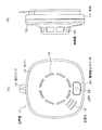
図1は本発明による住警器の外観を示した説明図であり、図1(A)に正面図を、図1(B)に側面図を示している。 FIG. 1 is an explanatory view showing the appearance of a house alarm device according to the present invention. FIG. 1 (A) shows a front view and FIG. 1 (B) shows a side view.
図1において、本実施形態の住警器10はカバー12と本体14で構成されている。カバー12の中央には、周囲に煙流入口を開口した検煙部16が配置され、火災による煙が所定濃度に達したときに火災を検出するようにしている。
In FIG. 1, the
カバー12に設けた検煙部16の左下側には音響孔18が設けられ、この背後にスピーカを内蔵し、警報音や音声メッセージを出力できるようにしている。検煙部16の下側には警報停止スイッチ20が設けられている。警報停止スイッチ20は点検スイッチとしての機能を兼ねている。
An acoustic hole 18 is provided on the lower left side of the
警報停止スイッチ20の内部には、点線で示すようにLED22が配置されており、LED22が点灯すると、警報停止スイッチ20のスイッチカバーの部分を透過してLED22の点灯状態が外部から分かるようにしている。
An
また本体14の裏側上部には取付フック15が設けられており、設置する部屋の壁にビスなどをねじ込み、このビスに取付フック15で取り付けることで、壁面に住警器10を設置することができる。
Also, a mounting hook 15 is provided on the upper back side of the main body 14, and a screw or the like is screwed into the wall of the room to be installed, and the mounting hook 15 is attached to this screw, so that the
住警器10は住宅の居間や寝室などの例えば壁面に設置され、万一、火災が発生した場合いには、火災を検出して警報を開始する。この火災を検出して警報を開始することを、住警器における「発報」という。
The
火災を検出した時の住警器10−4の警報音としては、例えば音声メッセージにより「ウーウー 火災警報器が作動しました 確認してください」を連続して出力する。同時にLED22を点滅又は明滅させる。住警器10が警報音を出している状態で、警報停止スイッチ20を操作すると、警報音が停止し、LED22が消灯する。
As an alarm sound of the residential alarm 10-4 when a fire is detected, for example, “Please confirm that the Woo fire alarm has been activated” is continuously output by voice message. At the same time, the
また住警器10は障害監視機能を備えており、障害を検知すると、例えば「ピッ」といった警報音を所定時間置きに間欠的に出力すると共にLED22を瞬時的に点灯し、障害が発生したことを報知する。住警器10から出力されている障害警報は、警報停止スイッチ20を操作することで停止することができる。
In addition, the
住警器10で検出して警報する障害とは、電池電圧の低下を検出して警報する電池容量低下警報(電池切れ警報)が主なものであり、これ以外に、検煙部などのセンサ障害など適宜の障害警報が含まれる。
The failure that is detected and alarmed by the
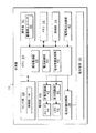
図2は本発明による住警器の実施形態を示したブロック図である。住警器10はCPU24を備え、CPU24に対しては、センサ部26、報知部28、操作部30、メモリ32、移報部34、電池電源36、電池試験回路部38及び電圧検出回路部40を設けている。
FIG. 2 is a block diagram showing an embodiment of a residential alarm according to the present invention. The
センサ部26には、本実施形態にあっては検煙部16が設けられ、煙濃度に応じた煙検出信号をCPU24に出力している。センサ部26には検煙部16以外に、火災による温度を検出するサーミスタを設けてもよい。またガス漏れ監視用の住警器の場合には、センサ部26にガス漏れセンサが設けられることになる。
In the present embodiment, the sensor unit 26 is provided with a
報知部28には音響回路部42により駆動されるスピーカ44と、表示回路部46により駆動されるLED22が設けられ、音、音と表示、又は表示により警報を含む情報を出力する。即ち、スピーカ44は、音声合成による音声メッセージ、警報音及び各種の報知音を出力する。LED22は点滅や明滅、点灯などにより、火災などの異常及び障害などを表示する。
The notification unit 28 is provided with a speaker 44 driven by the acoustic circuit unit 42 and an
操作部30には警報停止スイッチ20が設けられている。警報停止スイッチ20を操作すると、住警器10から流している警報音を停止することができる。警報停止スイッチ20は、本実施形態にあっては点検スイッチを兼用している。
The operation unit 30 is provided with an alarm stop switch 20. When the alarm stop switch 20 is operated, the alarm sound flowing from the
警報停止スイッチ20は、報知部28からスピーカ44により警報音を出力しているときに有効となる。一方、警報音を出力していない通常監視状態で警報停止スイッチ20は点検スイッチとして機能し、点検スイッチを押すと、報知部28から点検用の音声メッセージなどが出力される。 The alarm stop switch 20 is effective when an alarm sound is output from the notification unit 28 through the speaker 44. On the other hand, the alarm stop switch 20 functions as an inspection switch in a normal monitoring state in which no alarm sound is output. When the inspection switch is pressed, a notification voice message or the like is output from the notification unit 28.
電池電源36は、例えば所定セル数のアルカリ乾電池を使用しており、定格電圧として例えば5.0ボルトの電池電圧を供給し、電池容量としては住警器10における回路部全体の低消費電力化により、約10年の電池寿命を保証している。
The battery power source 36 uses, for example, an alkaline dry battery having a predetermined number of cells, supplies a battery voltage of, for example, 5.0 volts as the rated voltage, and reduces the power consumption of the entire circuit unit in the
CPU24にはプログラムの実行により実現される機能として、異常監視部48、電池試験部50及び電池容量監視部52が設けられている。異常監視部48は、センサ部26に設けた検煙部16からの煙検出信号が火災レベルを超えて火災を検出したときに、報知部28のスピーカ44から警報音例えば「ウーウー 火災警報器が作動しました 確認してください」を繰り返し出力させると共に、報知部28のLED22を例えば明滅させる。
The
また、異常監視部48は、移報部34に対し他の住警器からの移報信号線を接続している場合には、火災発報を示す移報信号を移報部34で受信したとき、報知部28のスピーカ44から警報音例えば「ウーウー 別の火災警報器が作動しました 確認してください」となる音声メッセージを連続的に出力させると共に、LED22を点滅させる。
In addition, the abnormality monitoring unit 48 receives a transmission signal indicating a fire alarm at the transmission unit 34 when the transmission unit 34 is connected with a transmission signal line from another resident alarm. At the same time, an alarm sound such as “Please confirm that another fire alarm has been activated” is output continuously from the speaker 44 of the notification unit 28, and the
電池試験部50は、電池試験回路部38に定期的、例えば4時間毎に試験指示信号を出力し、電池電源36に異常警報時と同等な負荷電流、例えば250mAを流す電池負荷試験を行って電圧検出回路部40により検出された電池電圧を取得させる。電池試験回路部38はCPU24から試験指示信号を受けているあいだトランジスタなどのスイッチ素子のオンにより電池電源36に試験用の抵抗を接続して異常警報時に相当する負荷電流を流す。
The battery test unit 50 outputs a test instruction signal to the battery
電池容量監視部52は、電池試験部50による電池負荷試験で検出した電池電圧が所定の閾値Vth1以下に低下したときに電池容量低下と判断し、報知部28から電池容量低下警報を間欠的に出力させると共に、その後の定期的な電池試験部38による電池負荷試験を停止させる。
The battery capacity monitoring unit 52 determines that the battery capacity has decreased when the battery voltage detected in the battery load test by the battery testing unit 50 has dropped below a predetermined threshold Vth1, and intermittently issues a battery capacity decrease alarm from the notification unit 28. At the same time, the battery load test by the subsequent
本実施形態にあっては、電池電源36の定格電圧5.0ボルトに対し、電池試験部50により異常警報時と同じ負荷電流250mAを流す負荷試験を行った時の電池電圧が閾値電圧Vth1として例えばVth1=2.35ボルト以下に低下した時に、電池容量低下と判断して電池容量低下警報を出すようにしている。 In the present embodiment, the battery voltage when the load test is performed in which the same load current 250 mA as that during the abnormality alarm is performed by the battery test unit 50 with respect to the rated voltage of 5.0 volts of the battery power source 36 is set as the threshold voltage Vth1. For example, when the voltage drops to Vth1 = 2.35 volts or less, it is determined that the battery capacity is low, and a battery capacity low alarm is issued.
また、電池容量監視部52は、電池容量の低下判断が少なくとも2回連続したときに報知部38から電池容量低下警報を出力させる。これは温度により電池容量が一時的に低下した場合の誤検出を防止するためである。
Further, the battery capacity monitoring unit 52 outputs a battery capacity reduction alarm from the
更に、電池容量監視部52は、報知部28から出力させる電池容量低下警報の駆動電流を、火災検出による異常警報の駆動電流である例えば250mAより低い駆動電流、例えば100mAに設定して警報させる。 Furthermore, the battery capacity monitoring unit 52 sets the driving current of the battery capacity lowering alarm output from the notification unit 28 to a driving current lower than 250 mA, for example, 100 mA, which is the driving current of the abnormal alarm due to the fire detection, and issues an alarm.
電池容量監視部52による電池容量低下警報は、電池容量の低下を断定した時に「ピッ 電池切れです」を3回出力し、同時に、警報音に同期してLED22を点滅させる。その後は、定期鳴動として例えば1分毎に「ピッ 電池切れです」といった警報音を3回出力する。また警報停止スイッチ20により点検操作(テスト操作)を行ったとき「ピッ 電池切れです」を1回出力し、同時にLED22を点滅させる。
The battery capacity lowering alarm by the battery capacity monitoring unit 52 outputs “Battery out of battery” three times when it is determined that the battery capacity has decreased, and at the same time, the
このように電池容量低下警報を出力する場合、正常時の警報駆動電流を250mAを100mAに低下させているため、その分、スピーカ44からの警報音は低下するが、警報音の聞き取りとしては問題のない充分なレベルの音となる。 In this way, when the battery capacity reduction alarm is output, the alarm driving current at normal time is reduced from 250 mA to 100 mA. Therefore, the alarm sound from the speaker 44 is reduced correspondingly, but it is a problem to hear the alarm sound. Sounds at a sufficient level without noise.
このように一度、電池容量低下が判断されて間欠的な電池容量低下警報の出力が開始された後は、電池負荷試験による電圧検出は停止されるが、時間の経過に伴って電池容量が低下し、CPU24が動作を停止する所定のリセット電圧Vth2、例えばVth2=2.0ボルトに低下するまで、報知部28から電池容量低下警報を間欠的に出力させることになる。
In this way, once the battery capacity reduction is determined and the output of the intermittent battery capacity reduction alarm is started, voltage detection by the battery load test is stopped, but the battery capacity decreases with time. Then, until the
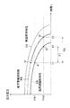
図3は本実施形態の警報器において電池容量の低下に伴う電池電圧の低下特性を示したグラフ図である。図3において、横軸は時間であり、縦軸に電池電源の電圧を示している。 FIG. 3 is a graph showing a battery voltage decrease characteristic associated with a decrease in battery capacity in the alarm device of the present embodiment. In FIG. 3, the horizontal axis represents time, and the vertical axis represents the voltage of the battery power source.
まず無負荷時特性54は、異常監視のみを行うことによる最も消費電流の低い状態であり、電池寿命は最も長くなる。 First, the no-load characteristic 54 is a state in which the current consumption is the lowest by performing only the abnormality monitoring, and the battery life is the longest.
負荷試験時特性56は電池容量の低下を判断するために定期的に異常警報時に相当する負荷電流250mAを流す電池負荷試験を行った場合の電池電圧の変化を示しており、時刻t1の電池負荷試験で電池電圧がA点に示すように閾値電圧Vth1=2.35ボルトに低下したとすると、この時点から電池容量低下警報の間欠出力が開始される。 A load test characteristic 56 indicates a change in battery voltage when a battery load test is performed in which a load current of 250 mA corresponding to an abnormal alarm is periodically sent to determine a decrease in battery capacity, and the battery load at time t1. Assuming that the battery voltage has dropped to the threshold voltage Vth1 = 2.35 volts as indicated by point A in the test, intermittent output of the battery capacity drop alarm is started from this point.
電池容量低下警報の動作電流は、異常警報時の動作電流250mAにより低い動作電流100mAに設定されているため、電池容量低下警報の出力を時刻t1から開始すると、電池電圧の低下特性は、負荷試験時特性56上のA点から動作電流が低下した低下警報時特性58上のB点に移行し、以後、低下警報時特性58に従い時間の経過に伴って電池電圧が低下することになる。
Since the operating current of the battery capacity lowering alarm is set to a lower operating current of 100 mA due to the operating current of 250 mA at the time of the abnormality alarm, when the output of the battery capacity lowering alarm is started from time t1, the battery voltage lowering characteristic is From point A on the time characteristic 56, the operating current decreases to point B on the drop alarm time characteristic 58, and thereafter the battery voltage decreases with the passage of time according to the drop
この場合、もし、電池負荷試験を停止せずに電池容量低下警報を間欠的に出力させたとすると、A点から負荷試験時特性56に従って時間の経過と共に電池電圧が低下し、時刻t2のC点で、CPU28のリセット電圧Vth2=2.0ボルトに低下し、警報器10の機能が失われる。
In this case, if the battery capacity reduction alarm is intermittently output without stopping the battery load test, the battery voltage decreases with time from the point A according to the load test characteristic 56, and the point C at time t2. Thus, the reset voltage Vth2 of the CPU 28 is lowered to 2.0 volts, and the function of the
しかしながら、本実施形態にあっては、定期的な電池負荷試験を停止し、且つ電池容量低下警報の動作電流を例えば250mAから100mAに低下させることで、低下警報時特性58を得ており、電池電圧がCPU28のリセット電圧Vth2=2.0ボルトに低下するのは時刻t3のD点となる。 However, in the present embodiment, the periodic battery load test is stopped, and the operating current of the battery capacity decrease alarm is decreased from, for example, 250 mA to 100 mA, thereby obtaining the characteristic 58 at the time of decrease alarm. The voltage drops to the reset voltage Vth2 = 2.0 volts of the CPU 28 at the point D at time t3.
この結果、負荷試験時特性56に従った警報器の電池容量使用可能期間T1を、低下警報時特性58に従った警報器の電池容量使用可能期間T2に延ばすことができる。
As a result, the battery capacity usable period T1 of the alarm device according to the load test time characteristic 56 can be extended to the battery capacity usable period T2 of the alarm device according to the deterioration
特に、電池容量使用可能期間T2の中の負荷試験時特性56に従った電池容量使用可能期間T1については、その間に火災検出が行われて異常警報のために250mAの動作電流が流れて電池電圧が低下しても、負荷試験時特性56に従った電圧に低下するだけであり、電池電圧がCPUリセット電圧Vth2=2.0ボルト以上にあることを保証している。 In particular, for the battery capacity usable period T1 according to the load test characteristic 56 in the battery capacity usable period T2, a fire detection is performed during that period, and an operating current of 250 mA flows for an abnormal alarm, so that the battery voltage Even if the voltage decreases, it only decreases to a voltage according to the load test characteristic 56, and the battery voltage is guaranteed to be equal to or higher than the CPU reset voltage Vth2 = 2.0 volts.
このため時刻t1から電池容量低下警報の間欠出力が開始されても、使用可能期間T1の間は、火災検出に対し正常に火災警報を出力させることができる。 For this reason, even if the intermittent output of the battery capacity reduction alarm is started from time t1, the fire alarm can be normally output for the fire detection during the usable period T1.
時刻t2以降については、低下警報時特性58に従った電池電圧の状態で火災検出により異常警報を出そうとすると、異常警報動作で電池電圧は、その時の負荷試験時特性56の電圧に低下し、この電圧はCPUリセット電圧Vth2以下となるため、CPUが停止して警報器の機能は停止してしまう。 After time t2, if an abnormal alarm is issued by detecting a fire in the state of the battery voltage in accordance with the decrease alarm characteristic 58, the battery voltage is reduced to the voltage of the load test characteristic 56 at that time by the abnormal alarm operation. Since this voltage is equal to or lower than the CPU reset voltage Vth2, the CPU stops and the function of the alarm stops.
しかしながら、電池容量低下警報については、低下警報時特性58に従って時刻t3のD点でCPUリセット電圧Vth2に低下するまで、間欠的に出力して報知することができ、長期間不在であっても、帰宅するまで可能な限り電池容量低下警報を出し続けることができる。
However, the battery capacity lowering alarm can be output and notified intermittently until it decreases to the CPU reset voltage Vth2 at the point D of time t3 according to the characteristic of lowering
また電池容量監視部52は、報知部28から異常警報以外の全ての音、音と表示、又は表示の駆動電流を、電池容量低下を判断する前の駆動電流より低い駆動電流に設定するようにしても良い。 Further, the battery capacity monitoring unit 52 sets all the sounds, sounds and displays, or display drive currents other than the abnormality alarm from the notification unit 28 to a drive current lower than the drive current before the battery capacity decrease is determined. May be.
電池容量監視部52が電池容量低下を判断する前の駆動電流より低い駆動電流に設定して出力する情報としては例えば次のものがある。
(1)正常時に点検操作(テスト操作)を行ったときの情報(例:「ピッピッピッ 火事です 火事です 正常です」)
(2)正常時に移報点検操作(移報テスト操作)を行ったときの情報(例:「「ピッピッピッ 移報テストをはじめます」)
(3)センサ障害時に定期的に出力される情報(例:所定時間毎に「ピッ 故障です」を所定回数出力)
(4)センサ障害時に点検操作(テスト操作)を行ったときの情報(例:「ピッ 故障です」を1回出力)
また、電池容量監視部52は、報知部28から出力させる火災警報の駆動電流を、電池容量低下を判断する前の駆動電流より低い駆動電流に設定するようにしても良い。
Examples of information that is output by setting the drive current lower than the drive current before the battery capacity monitoring unit 52 determines that the battery capacity has decreased are as follows.
(1) Information when the inspection operation (test operation) is performed under normal conditions (Example: “It ’s a fire. A fire is normal.”)
(2) Information when the transfer inspection operation (transfer test operation) is performed in a normal state (Example: “Start the beeping transfer test”)
(3) Information that is periodically output when a sensor failure occurs (Example: “Pit failure” is output a predetermined number of times every predetermined time)
(4) Information when inspection operation (test operation) is performed at the time of sensor failure (Example: “It is a pin failure” is output once)
Further, the battery capacity monitoring unit 52 may set the driving current of the fire alarm output from the notification unit 28 to a driving current lower than the driving current before determining the battery capacity reduction.
このように、電池容量低下を判断した後は、報知部28から火災警報もしくは火災警報以外の音、音と表示、又は表示の駆動電流を、電池容量低下を判断する前の駆動電流より低い駆動電流に設定することで、電池容量低下警報を出すことのできる期間をさらに長く確保することができる。 As described above, after determining the battery capacity reduction, the alarm 28 emits a sound, sound and display other than the fire alarm, or the display drive current is lower than the drive current before the battery capacity decrease is determined. By setting the current, it is possible to secure a longer period during which the battery capacity reduction alarm can be issued.
図4は図2の住警器10に設けたCPU24による処理動作を示したフローチャートである。図4において、住警器10に設けている電池電源36の電極シールなどを外すことにより、CPU24を含む各回路部に対し電源を供給すると、CPU24は、ステップS1でハードウェアチェックを含む初期化処理を行った後、ステップS2で正常か否か判別し、もし異常があれば音声異常終了メッセージなどを出力して異常終了となり、正常であればステップS3に進み、センサ部26に設けた検煙部16からの煙検出信号が所定の火災レベルを超えるか否かで火災発報の有無を判別している。
FIG. 4 is a flowchart showing the processing operation by the
ステップS3で火災発報が判別された場合にはステップS4に進み、火災警報を報知部28のスピーカ44から音響出力及びLED22の点灯制御で出力する。火災警報を行った後は、ステップS5で警報停止スイッチ20による警報停止操作の有無を判別しており、警報停止操作があれば、ステップS6で警報停止を行う。
If a fire report is determined in step S3, the process proceeds to step S4, and a fire alarm is output from the speaker 44 of the notification unit 28 by sound output and
続いてステップS7で例えば4時間単位に設定した電池容量監視タイミングか否か判別し、電池容量監視タイミングへの到達を判別するとステップS8に進み、電池容量低下を判定済みか否かチェックする。 Subsequently, in step S7, it is determined whether or not the battery capacity monitoring timing is set, for example, in units of 4 hours. If it is determined that the battery capacity monitoring timing has been reached, the process proceeds to step S8, and it is checked whether or not the battery capacity reduction has been determined.
電池容量低下の判定がそれ以前に得られていない場合はステップS9に進み、電池試験回路部38を動作して電池電源36に試験用の抵抗を一時的に接続して負荷電流250mAを流し、この状態で電圧検出回路部40で検出した電池電圧を読み込む。
When the determination of the battery capacity reduction has not been obtained before, the process proceeds to step S9, the battery
続いてステップS10で検出した電池電圧が電池容量低下を判断する閾値電圧vth1以下か否か判別し、閾値電圧以下であればステップS11で電池容量低下を判定する。続いてステップS12で連続して2回目の電池容量低下判定か否かチェックし、1回目であればステップS3に戻り、次の電池容量低下の判定を行うことになる。 Subsequently, it is determined whether or not the battery voltage detected in step S10 is equal to or less than a threshold voltage vth1 for determining a decrease in battery capacity. If it is equal to or less than the threshold voltage, a decrease in battery capacity is determined in step S11. Subsequently, in step S12, it is continuously checked whether or not the battery capacity reduction determination is the second time, and if it is the first time, the process returns to step S3 to determine the next battery capacity reduction.
ステップS11で連続して2回目の電池容量低下の判定であることを判別すると、ステップS13でそれ以降の電池負荷試験を禁止した後、ステップS14で電池容量低下警報の動作電流を、例えば警報時の250mAから100mAに抑制する。 If it is determined in step S11 that the determination is the second battery capacity decrease continuously, after the battery load test is prohibited in step S13, the operation current of the battery capacity decrease alarm is set in step S14, for example, at the time of alarm. From 250 mA to 100 mA.
続いてステップS15で電池容量低下の警報タイミングの有無をチェックし、警報タイミングへの到達を判別する毎にステップS16に進んで報知部28のスピーカ44による警報音及びLED22の点灯による電池容量低下警報を出力させる。
Subsequently, in step S15, the presence or absence of a battery capacity decrease alarm timing is checked. Every time it is determined that the alarm timing has been reached, the process proceeds to step S16, where the alarm sound from the speaker 44 of the notification unit 28 and the battery capacity decrease alarm due to the lighting of the
なお、上記の実施形態は火災検出を対象とした住警器を例に取るものであったが、これ以外にガス漏れ警報器や防犯用の警報器など、それ以外の適宜の異常を検出する警報器につき、本実施形態をそのまま適用できる。また住宅用に限らず、ビルやオフィス用などの各種の用途の警報器にも適用できる。 In addition, although said embodiment took the resident alarm for fire detection as an example, in addition to this, other appropriate abnormalities, such as a gas leak alarm and a security alarm, are detected. The present embodiment can be applied to the alarm device as it is. Moreover, the present invention can be applied not only to residential use but also to alarm devices for various uses such as buildings and offices.
また上記の実施形態は警報器にセンサ部を一体に設けた場合を例に取るものであったが、他の実施形態として警報器からセンサ部を別体として設けた警報器であっても良い。 Moreover, although said embodiment took the case where the sensor part was integrally provided in the alarm device as an example, as another embodiment, the alarm device which provided the sensor part separately from the alarm device may be sufficient. .
また、上記の実施形態にあっては、定期的な電池負荷試験による電池電圧の低下により2回連続して電池容量低下が判定された時に電池容量低下警報の間欠出力を開始しているが、1回もしくは3回以上の判定で電池容量低下警報の間欠出力を開始しても良い。 In the above embodiment, intermittent output of the battery capacity decrease alarm is started when it is determined that the battery capacity decrease is continuously performed twice due to the battery voltage decrease by the periodic battery load test. Intermittent output of a battery capacity reduction alarm may be started once or three or more times.
また本発明は上記の実施形態に限定されず、その目的と利点を損なうことのない適宜の変形を含み、更に上記の実施形態に示した数値による限定は受けない。
The present invention is not limited to the above-described embodiments, includes appropriate modifications that do not impair the objects and advantages thereof, and is not limited by the numerical values shown in the above-described embodiments.
10:住警器
12:カバー
14:本体
15:取付フック
16:検煙部
18:音響孔
20:警報停止スイッチ
22:LED
24:CPU
26:センサ部
28:CPU
30:操作部
32:メモリ
34:移報部
36:電池電源
38:電池試験回路部
40:電圧検出回路部
42:音響回路部
44:スピーカ
46:表示回路部
48:異常監視部
50:電池試験部
52:電池容量監視部
54:無負荷時特性
56:負荷試験時特性
58:低下警報時特性
10: House alarm 12: Cover 14: Body 15: Mounting hook 16: Smoke detector 18: Sound hole 20: Alarm stop switch 22: LED
24: CPU
26: Sensor unit 28: CPU
30: Operation section 32: Memory 34: Transfer section 36: Battery power supply 38: Battery test circuit section 40: Voltage detection circuit section 42: Acoustic circuit section 44: Speaker 46: Display circuit section 48: Abnormality monitoring section 50: Battery test Unit 52: Battery capacity monitoring unit 54: No load characteristic 56: Load test characteristic 58: Decrease alarm characteristic
Claims (7)
警報器と別体又は一体に設けられ、異常を検出するセンサ部と、
音、音と表示、又は表示により警報を含む情報を出力する報知部と、
前記センサ部からの異常検出信号を受けて前記報知部から異常警報を出力させる異常監視部と、
を備えた警報器に於いて、
定期的に前記電池電源に異常警報時と同等な負荷電流を流す電池負荷試験を行って電池電圧を検出する電池試験部と、
前記電池負荷試験により検出した電池電圧が所定の閾値以下に低下したときに電池容量低下と判断し、前記報知部から電池容量低下警報を間欠的に出力させると共に、その後の定期的な前記電池負荷試験を停止させる電池容量監視部と、
を設けたことを特徴とする警報器。
Battery power,
A sensor unit that is provided separately or integrally with the alarm device and detects an abnormality,
A notification unit for outputting information including a warning by sound, sound and display, or display;
An abnormality monitoring unit that receives an abnormality detection signal from the sensor unit and outputs an abnormality alarm from the notification unit;
In an alarm device equipped with
A battery test unit for periodically detecting a battery voltage by conducting a battery load test in which a load current equivalent to that at the time of an abnormality alarm is supplied to the battery power source;
When the battery voltage detected by the battery load test falls below a predetermined threshold, it is determined that the battery capacity is low, and a battery capacity drop alarm is intermittently output from the notification unit, and the battery load periodically thereafter A battery capacity monitoring unit for stopping the test;
An alarm device characterized by providing.
The alarm device according to claim 1, wherein the battery capacity monitoring unit outputs a battery capacity decrease alarm from the notification unit when the battery capacity decrease determination is continued at least twice. .
2. The alarm device according to claim 1, wherein the battery capacity monitoring unit sets the driving current of the battery capacity lowering alarm output from the notification unit to a driving current lower than the driving current of the abnormality alarm and issues an alarm. 3. Alarm device characterized by.
2. The alarm device according to claim 1, wherein the battery capacity monitoring unit is configured to obtain a sound, sound and display other than an abnormal alarm from the notification unit, or a drive current of display based on a drive current before determining a decrease in battery capacity. An alarm device characterized by setting a low driving current.
The alarm device according to claim 4, wherein the battery capacity monitoring unit sets information to be output by setting a drive current lower than the drive current before determining a decrease in battery capacity, information associated with a normal inspection operation, An alarm device comprising information associated with a normal inspection operation, periodic notification information when a sensor failure occurs, and information associated with an inspection operation when a sensor failure occurs.
2. The alarm device according to claim 1, wherein the battery capacity monitoring unit sets a driving current of an abnormality alarm output from the notification unit to a driving current lower than a driving current before determining a decrease in battery capacity. Alarm device characterized.
Priority Applications (1)
| Application Number | Priority Date | Filing Date | Title |
|---|---|---|---|
| JP2009147204A JP5475337B2 (en) | 2008-08-25 | 2009-06-22 | Alarm |
Applications Claiming Priority (3)
| Application Number | Priority Date | Filing Date | Title |
|---|---|---|---|
| JP2008215096 | 2008-08-25 | ||
| JP2008215096 | 2008-08-25 | ||
| JP2009147204A JP5475337B2 (en) | 2008-08-25 | 2009-06-22 | Alarm |
Publications (2)
| Publication Number | Publication Date |
|---|---|
| JP2010079876A true JP2010079876A (en) | 2010-04-08 |
| JP5475337B2 JP5475337B2 (en) | 2014-04-16 |
Family
ID=42210193
Family Applications (1)
| Application Number | Title | Priority Date | Filing Date |
|---|---|---|---|
| JP2009147204A Active JP5475337B2 (en) | 2008-08-25 | 2009-06-22 | Alarm |
Country Status (1)
| Country | Link |
|---|---|
| JP (1) | JP5475337B2 (en) |
Cited By (5)
| Publication number | Priority date | Publication date | Assignee | Title |
|---|---|---|---|---|
| JP2011237954A (en) * | 2010-05-10 | 2011-11-24 | Hochiki Corp | Multifunctional operation device |
| JP2011248425A (en) * | 2010-05-24 | 2011-12-08 | Hochiki Corp | Alarm unit |
| JP2013033414A (en) * | 2011-08-03 | 2013-02-14 | Nohmi Bosai Ltd | Alarm |
| JP2015092389A (en) * | 2014-12-29 | 2015-05-14 | ホーチキ株式会社 | Alarm |
| JP2019040232A (en) * | 2017-08-22 | 2019-03-14 | ホーチキ株式会社 | Alarm device |
Citations (12)
| Publication number | Priority date | Publication date | Assignee | Title |
|---|---|---|---|---|
| JPH0285782A (en) * | 1987-02-23 | 1990-03-27 | Takenaka Komuten Co Ltd | Alarm device |
| JPH0470582A (en) * | 1990-07-11 | 1992-03-05 | Pfu Ltd | Battery test method in power source circuit |
| JPH0749988A (en) * | 1993-06-15 | 1995-02-21 | Hochiki Corp | Radio alarm device |
| JPH09120496A (en) * | 1995-10-26 | 1997-05-06 | Hochiki Corp | Stand-by power source testing device for fire monitoring control panel |
| JPH09147926A (en) * | 1995-11-17 | 1997-06-06 | Nittan Co Ltd | Auxiliary power supply test device and auxiliary power supply test method, and fire monitor system |
| JP2004279417A (en) * | 2003-03-12 | 2004-10-07 | Renishaw Plc | Determination of battery life |
| JP2004362537A (en) * | 2003-05-09 | 2004-12-24 | Tokyo Gas Co Ltd | Fire alarm and battery life setting method |
| JP2005044317A (en) * | 2003-07-25 | 2005-02-17 | Nohmi Bosai Ltd | Fire alarm |
| JP2006031451A (en) * | 2004-07-16 | 2006-02-02 | Hochiki Corp | Alarm |
| JP2007011829A (en) * | 2005-07-01 | 2007-01-18 | Hochiki Corp | Alarm unit |
| JP2007265102A (en) * | 2006-03-29 | 2007-10-11 | Nohmi Bosai Ltd | Fire alarm |
| JP2008065621A (en) * | 2006-09-07 | 2008-03-21 | Fuji Electric Fa Components & Systems Co Ltd | Battery-operated alarm |
-
2009
- 2009-06-22 JP JP2009147204A patent/JP5475337B2/en active Active
Patent Citations (12)
| Publication number | Priority date | Publication date | Assignee | Title |
|---|---|---|---|---|
| JPH0285782A (en) * | 1987-02-23 | 1990-03-27 | Takenaka Komuten Co Ltd | Alarm device |
| JPH0470582A (en) * | 1990-07-11 | 1992-03-05 | Pfu Ltd | Battery test method in power source circuit |
| JPH0749988A (en) * | 1993-06-15 | 1995-02-21 | Hochiki Corp | Radio alarm device |
| JPH09120496A (en) * | 1995-10-26 | 1997-05-06 | Hochiki Corp | Stand-by power source testing device for fire monitoring control panel |
| JPH09147926A (en) * | 1995-11-17 | 1997-06-06 | Nittan Co Ltd | Auxiliary power supply test device and auxiliary power supply test method, and fire monitor system |
| JP2004279417A (en) * | 2003-03-12 | 2004-10-07 | Renishaw Plc | Determination of battery life |
| JP2004362537A (en) * | 2003-05-09 | 2004-12-24 | Tokyo Gas Co Ltd | Fire alarm and battery life setting method |
| JP2005044317A (en) * | 2003-07-25 | 2005-02-17 | Nohmi Bosai Ltd | Fire alarm |
| JP2006031451A (en) * | 2004-07-16 | 2006-02-02 | Hochiki Corp | Alarm |
| JP2007011829A (en) * | 2005-07-01 | 2007-01-18 | Hochiki Corp | Alarm unit |
| JP2007265102A (en) * | 2006-03-29 | 2007-10-11 | Nohmi Bosai Ltd | Fire alarm |
| JP2008065621A (en) * | 2006-09-07 | 2008-03-21 | Fuji Electric Fa Components & Systems Co Ltd | Battery-operated alarm |
Cited By (6)
| Publication number | Priority date | Publication date | Assignee | Title |
|---|---|---|---|---|
| JP2011237954A (en) * | 2010-05-10 | 2011-11-24 | Hochiki Corp | Multifunctional operation device |
| JP2011248425A (en) * | 2010-05-24 | 2011-12-08 | Hochiki Corp | Alarm unit |
| JP2013033414A (en) * | 2011-08-03 | 2013-02-14 | Nohmi Bosai Ltd | Alarm |
| JP2015092389A (en) * | 2014-12-29 | 2015-05-14 | ホーチキ株式会社 | Alarm |
| JP2019040232A (en) * | 2017-08-22 | 2019-03-14 | ホーチキ株式会社 | Alarm device |
| JP7091037B2 (en) | 2017-08-22 | 2022-06-27 | ホーチキ株式会社 | Alarm |
Also Published As
| Publication number | Publication date |
|---|---|
| JP5475337B2 (en) | 2014-04-16 |
Similar Documents
| Publication | Publication Date | Title |
|---|---|---|
| JP4865263B2 (en) | Fire alarm | |
| JP4584778B2 (en) | Alarm | |
| JP5475337B2 (en) | Alarm | |
| JP2009146232A (en) | Alarm | |
| JP4051626B2 (en) | Fire alarm | |
| JP5114699B2 (en) | Battery voltage drop detection device | |
| JP2011076358A (en) | Fire alarm for housing | |
| JP5416028B2 (en) | Multi-function operating device | |
| JP2005208957A (en) | Alarm | |
| JP4885999B2 (en) | Alarm | |
| JP5676144B2 (en) | Alarm | |
| JP4331065B2 (en) | Alarm | |
| JP4211030B2 (en) | Fire alarm | |
| JP2014157440A (en) | Fire alarm facilities | |
| JP2005293308A (en) | Fire alarm | |
| JP5396260B2 (en) | Alarm | |
| JP5567873B2 (en) | Multi-function operating device | |
| JP5638839B2 (en) | Alarm | |
| JP2015092389A (en) | Alarm | |
| JP4934731B2 (en) | Alarm | |
| JP6700464B1 (en) | Alarm | |
| JP2020123077A (en) | Alarm | |
| JP2011014062A (en) | Alarm | |
| JP3181785U (en) | Alarm | |
| JP3181786U (en) | Alarm |
Legal Events
| Date | Code | Title | Description |
|---|---|---|---|
| A621 | Written request for application examination |
Free format text: JAPANESE INTERMEDIATE CODE: A621 Effective date: 20120522 |
|
| A131 | Notification of reasons for refusal |
Free format text: JAPANESE INTERMEDIATE CODE: A131 Effective date: 20130305 |
|
| A977 | Report on retrieval |
Free format text: JAPANESE INTERMEDIATE CODE: A971007 Effective date: 20130306 |
|
| A521 | Written amendment |
Free format text: JAPANESE INTERMEDIATE CODE: A523 Effective date: 20130507 |
|
| A131 | Notification of reasons for refusal |
Free format text: JAPANESE INTERMEDIATE CODE: A131 Effective date: 20130820 |
|
| TRDD | Decision of grant or rejection written | ||
| A01 | Written decision to grant a patent or to grant a registration (utility model) |
Free format text: JAPANESE INTERMEDIATE CODE: A01 Effective date: 20140114 |
|
| A61 | First payment of annual fees (during grant procedure) |
Free format text: JAPANESE INTERMEDIATE CODE: A61 Effective date: 20140206 |
|
| R150 | Certificate of patent or registration of utility model |
Ref document number: 5475337 Country of ref document: JP Free format text: JAPANESE INTERMEDIATE CODE: R150 Free format text: JAPANESE INTERMEDIATE CODE: R150 |