JP2010079205A - Image forming apparatus and developing cartridge - Google Patents
Image forming apparatus and developing cartridge Download PDFInfo
- Publication number
- JP2010079205A JP2010079205A JP2008250541A JP2008250541A JP2010079205A JP 2010079205 A JP2010079205 A JP 2010079205A JP 2008250541 A JP2008250541 A JP 2008250541A JP 2008250541 A JP2008250541 A JP 2008250541A JP 2010079205 A JP2010079205 A JP 2010079205A
- Authority
- JP
- Japan
- Prior art keywords
- gripping member
- housing
- unit
- end surface
- handle
- Prior art date
- Legal status (The legal status is an assumption and is not a legal conclusion. Google has not performed a legal analysis and makes no representation as to the accuracy of the status listed.)
- Granted
Links
- 230000004308 accommodation Effects 0.000 claims description 6
- 108091008695 photoreceptors Proteins 0.000 abstract 2
- 230000006835 compression Effects 0.000 description 10
- 238000007906 compression Methods 0.000 description 10
- 230000001105 regulatory effect Effects 0.000 description 6
- 238000000034 method Methods 0.000 description 5
- 238000010438 heat treatment Methods 0.000 description 3
- 230000015572 biosynthetic process Effects 0.000 description 2
- 238000011144 upstream manufacturing Methods 0.000 description 2
- 239000003086 colorant Substances 0.000 description 1
- 230000000694 effects Effects 0.000 description 1
- 238000000605 extraction Methods 0.000 description 1
- 238000003780 insertion Methods 0.000 description 1
- 230000037431 insertion Effects 0.000 description 1
- 230000000149 penetrating effect Effects 0.000 description 1
- 238000000926 separation method Methods 0.000 description 1
Images


Abstract
Description
本発明は、カラープリンタなどの画像形成装置、および、その画像形成装置に装着される現像カートリッジに関する。 The present invention relates to an image forming apparatus such as a color printer, and a developing cartridge attached to the image forming apparatus.
電子写真方式のプリンタなどの画像形成装置において、静電潜像が形成される感光ドラムを備える画像形成装置本体に対して、感光ドラムにトナーを供給するための現像ローラを備える現像カートリッジを着脱可能にするものが知られている。 In an image forming apparatus such as an electrophotographic printer, a developing cartridge including a developing roller for supplying toner to the photosensitive drum can be attached to and detached from an image forming apparatus main body including a photosensitive drum on which an electrostatic latent image is formed. What is to be known.
そして、画像形成時において、感光ドラムに対して現像ローラを圧接させるために、現像カートリッジを感光ドラムに向けて押圧状態で画像形成装置本体側に固定することが提案されている。 In order to press the developing roller against the photosensitive drum during image formation, it has been proposed to fix the developing cartridge to the image forming apparatus main body in a pressed state toward the photosensitive drum.
たとえば、現像カートリッジの上壁に、現像カートリッジを押圧する回動可能な取っ手と、取っ手と当接する当接部材とを設け、取っ手を起立状態の押圧解除位置から押圧方向へ回動させて傾倒状態の押圧位置へ移動させて、当接部材を押し下げることにより、現像カートリッジを感光ドラムに向けて押圧することが提案されている。(たとえば、特許文献1参照。)。
しかるに、特許文献1では、現像カートリッジを装着するときに、取っ手を回動させて傾倒状態にすることにより、現像カートリッジを感光ドラムに向けて押圧している。
However, in
そのため、現像カートリッジを離脱させるには、傾倒状態の取っ手を押圧解除方向に回動させ、起立させてから把持するので、取っ手を把持しにくく、現像カートリッジを離脱させにくい場合がある。 For this reason, in order to remove the developing cartridge, the handle in the tilted state is rotated in the pressing release direction and is held after being raised, so that it may be difficult to hold the handle and to remove the developing cartridge.
そこで、本発明では、把持部材を容易に把持することができ、着脱しやすい現像カートリッジを提供することにある。 Accordingly, an object of the present invention is to provide a developing cartridge that can easily grip a gripping member and is easy to attach and detach.
上記目的を達成するため、請求項1に記載の発明は、画像形成装置であって、装置本体と、並列配置された複数の感光体ドラムを有し、前記装置本体に対して前記複数の感光体ドラムの並列方向に、収容位置と引出位置との間でスライド移動可能に構成される感光体ユニットと、各前記感光体ドラムに対応して設けられ、前記感光体ユニットが前記引出位置にあるときに、前記感光体ユニットに対して着脱自在に構成される複数の現像カートリッジと、上面を有し、前記感光体ユニットが前記収容位置にあるときに、前記感光体ユニットを収容するためのユニット収容部とを備え、各前記現像カートリッジは、前記ユニット収容部の上面に対向し、前記感光体ユニットのスライド方向の前記収容位置側から前記引出位置側に向けて徐々に前記上面との距離が大きくなるように傾斜する端面を有する筐体と、前記筐体の端面と前記ユニット収容部の上面との間に設けられ、前記感光体ユニットが前記収容位置にあるときの第1位置と、前記感光体ユニットが引出位置にあるときの第2位置との間をスライド自在に構成される把持部材と、前記把持部材を前記第2位置側に向かって付勢する第1付勢手段と、前記筐体の前記端面の第1位置側に設けられ、前記把持部材が前記第1位置にあるときには、前記把持部材から押圧力を受けて前記筐体を前記感光体ドラムに向けて付勢し、前記把持部材が前記第2位置にあるときには、前記把持部材から押圧力を受けない位置にある第2付勢手段とを備えることを特徴としている。
In order to achieve the above object, an invention according to
また、請求項2に記載の発明は、請求項1に記載の発明において、前記把持部材の前記第1位置側端部には、前記ユニット収容部の上面に向かって突出する突出部が形成されていることを特徴としている。 According to a second aspect of the present invention, in the first aspect of the present invention, the first position side end of the gripping member is formed with a protruding portion that protrudes toward the upper surface of the unit accommodating portion. It is characterized by having.
また、請求項3に記載の発明は、請求項1または2に記載の発明において、前記筐体の前記端面には、前記第1位置側端部に切欠部が形成され、前記第2付勢手段は、前記切欠部の前記感光体ドラムの軸方向両端に配置されていることを特徴としている。 According to a third aspect of the present invention, in the first or second aspect of the present invention, the end surface of the casing is formed with a notch at the first position side end, and the second urging force is provided. The means is arranged at both ends of the notch in the axial direction of the photosensitive drum.
また、請求項4に記載の発明は、請求項1ないし3のいずれかに記載の発明において、前記把持部材の前記感光体ドラムの軸方向両端には、そのスライド方向に沿って延びるとともに外側に突出する突条が形成され、前記筐体の前記端面には、前記突条がスライド自在に嵌合され、前記第2位置側から前記第1位置側に向かうに従い、前記スライド方向と直交する方向の幅が拡がるように、ガイド溝が形成されていることを特徴としている。 According to a fourth aspect of the present invention, in the invention according to any one of the first to third aspects, the gripping member extends along the sliding direction at both ends in the axial direction of the photosensitive drum and outwards. A protruding ridge is formed, and the ridge is slidably fitted to the end surface of the housing, and a direction orthogonal to the sliding direction as it goes from the second position side to the first position side. A guide groove is formed so as to increase the width of the guide.
また、請求項5に記載の発明は、請求項1ないし4のいずれかに記載の発明において、前記把持部材の前記筐体の端面と対向している面の前記第1位置側端部には、前記第1位置側に向かうに従い、前記把持部材と前記筐体の端面との間隔が拡がるように傾斜する傾斜部が形成されていることを特徴としている。
The invention according to
また、請求項6に記載の発明は、請求項1ないし5のいずれかに記載の発明において、前記第1付勢手段は、前記筐体の前記端面の前記第2位置側に設けられていることを特徴としている。
The invention according to claim 6 is the invention according to any one of
また、請求項7に記載の発明は、現像カートリッジであって、一端側に端面を有する筐体と、前記筐体の他端側に回転自在に支持される現像剤担持体と、前記筐体の前記端面に設けられ、前記端面の一端側の第1位置と前記端面の他端側の第2位置とをスライド自在に構成される把持部材と、前記把持部材を第2位置側に向かって付勢する第1付勢部材と、前記端面の前記第1位置側端部に設けられ、前記把持部材が前記第1位置にあるときには、前記把持部材から押圧力を受けて前記筐体を前記把持部材から前記現像剤担持体に向かう方向に付勢し、前記把持部材が前記第2位置にあるときには、前記把持部材から押圧力を受けない位置にある第2付勢部材とを備え、前記把持部材は、前記第1位置に配置されているときには、前記筐体に対して前記把持部材から前記現像剤担持体に向かう方向に遊動可能に構成されていることを特徴としている。
The invention according to
また、請求項8に記載の発明は、請求項7に記載の発明において、前記把持部材の前記現像剤担持体の軸方向両端には、そのスライド方向に沿って延びるとともに外側に突出する突条が形成され、前記筐体の前記端面には、前記突条がスライド自在に嵌合され、前記第2位置側から前記第1位置側に向かうに従い、前記スライド方向と直交する方向の幅が拡がるように、ガイド溝が形成されていることを特徴としている。 According to an eighth aspect of the present invention, in the seventh aspect of the present invention, at the both ends in the axial direction of the developer carrier of the gripping member, the protrusions that extend along the sliding direction and project outward. The protrusion is slidably fitted to the end surface of the housing, and the width in the direction orthogonal to the sliding direction increases as it goes from the second position side to the first position side. As described above, a guide groove is formed.
また、請求項9に記載の発明は、請求項7または8に記載の発明において、前記把持部材の前記筐体の端面と対向している面の前記第1位置側端部には、前記第1位置側に向かうに従い、前記把持部材と前記筐体の端面との間隔が拡がるように傾斜する傾斜部が形成されていることを特徴としている。
The invention according to claim 9 is the invention according to
請求項1に記載の発明によれば、感光体ユニットが引出位置にあるときに、感光体ユニットに対して現像カートリッジを装着すると、その筐体の端面に配置される把持部材は、第1付勢手段の付勢力により、第2位置に配置される。このとき、第2付勢手段は、把持部材からの押圧力を受けない位置にある。 According to the first aspect of the present invention, when the developing cartridge is attached to the photoconductor unit when the photoconductor unit is in the pulled-out position, the gripping member disposed on the end surface of the housing is the first attached. It arrange | positions in a 2nd position with the urging | biasing force of a biasing means. At this time, the second urging means is in a position where it does not receive a pressing force from the gripping member.
次いで、感光体ユニットを、装置本体に対して引出位置から収容位置へスライド移動させると、ユニット収容部の上面に把持部材が干渉し、把持部材には第1位置側へ向かう押圧力が作用する。そのため、把持部材は、第1付勢手段の付勢力に抗して、筐体の端面の傾斜に沿って第1位置へスライドする。このとき、把持部材は、ユニット収容部の上面との間の摺接により生じる摩擦により、第1位置へと動きやすくなる。 Next, when the photosensitive unit is slid from the pulling position to the housing position with respect to the apparatus main body, the gripping member interferes with the upper surface of the unit housing portion, and a pressing force toward the first position acts on the gripping member. . Therefore, the gripping member slides to the first position along the inclination of the end surface of the housing against the urging force of the first urging means. At this time, the gripping member is easily moved to the first position due to friction generated by sliding contact with the upper surface of the unit housing portion.
そして、感光体ユニットが収容位置に位置すると、把持部材は、第1付勢手段の付勢力に抗して、第1位置に位置される。すると、第2付勢手段は、把持部材から押圧力を受けて、筐体を感光体ドラムに向けて付勢する。これによって、感光体ユニットが収容位置にあるときには、現像カートリッジの感光体ドラムに対する、確実な圧接を確保することができる。 When the photosensitive unit is positioned at the storage position, the gripping member is positioned at the first position against the biasing force of the first biasing means. Then, the second urging means receives a pressing force from the gripping member and urges the casing toward the photosensitive drum. As a result, when the photosensitive unit is in the storage position, it is possible to ensure a reliable press contact of the developing cartridge to the photosensitive drum.
一方、感光体ユニットを、装置本体に対して収容位置から引出位置へスライド移動させると、ユニット収容部の上面と把持部材との干渉がなくなることにより、把持部材には、第1付勢手段により、第2位置側へ向かう付勢力が作用する。そのため、把持部材は、第1付勢手段の付勢力により、筐体の端面の傾斜に沿って第2位置へスライドする。 On the other hand, when the photoconductor unit is slid from the housing position to the pulled-out position with respect to the apparatus main body, interference between the upper surface of the unit housing portion and the gripping member is eliminated. A biasing force toward the second position acts. Therefore, the gripping member slides to the second position along the inclination of the end surface of the housing by the biasing force of the first biasing means.
そして、感光体ユニットが引出位置に位置すると、把持部材は、第1付勢手段の付勢力により第2位置に位置される。すると、第2付勢手段は、把持部材からの押圧力を受けない位置に位置される。これによって、感光体ユニットが引出位置にあるときには、現像カートリッジの感光体ドラムに対する、確実な圧接解除を確保することができる。 When the photoconductor unit is located at the drawing position, the gripping member is located at the second position by the urging force of the first urging means. Then, the second urging means is positioned at a position where it does not receive a pressing force from the gripping member. As a result, when the photosensitive unit is in the pulled-out position, it is possible to ensure reliable release of the pressure contact with respect to the photosensitive drum of the developing cartridge.
また、把持部材が第2位置に位置されると、第2付勢手段が、把持部材からの押圧力を受けない位置に位置されるので、並列方向において隣接する各現像カートリッジの把持部材は、第2付勢手段が設けられている空間に相当する間隔を隔てて配置される。そのため、把持部材をそのまま把持して、現像カートリッジを容易に離脱させることができる。また、把持部材が第1位置より第2位置に位置した方が、把持部材は、上方に位置するため、さらに、把持部材を把持しやすくできる。 Further, when the gripping member is positioned at the second position, the second urging means is positioned at a position where it does not receive the pressing force from the gripping member, so that the gripping member of each developing cartridge adjacent in the parallel direction is It arrange | positions at intervals corresponding to the space in which the 2nd biasing means is provided. Therefore, the developing cartridge can be easily detached by holding the holding member as it is. Further, since the gripping member is positioned higher when the gripping member is positioned at the second position than the first position, the gripping member can be further easily gripped.
このように、請求項1に記載の発明によれば、感光体ユニットが収容位置にあるときには、現像カートリッジの感光体ドラムに対する、確実な圧接を確保することができ、また、感光体ユニットが引出位置にあるときには、現像カートリッジの感光体ドラムに対する、確実な圧接解除を確保することができる。さらに、感光体ユニットが引出位置にあるときには、把持部材をそのまま把持して、感光体ユニットに対して現像カートリッジを容易に離脱させることができる。 As described above, according to the first aspect of the present invention, when the photosensitive unit is in the storage position, it is possible to ensure a reliable pressure contact with the photosensitive drum of the developing cartridge, and the photosensitive unit is pulled out. When in the position, it is possible to ensure release of the pressure contact with respect to the photosensitive drum of the developing cartridge. Further, when the photosensitive unit is in the pulled-out position, the developing cartridge can be easily detached from the photosensitive unit by holding the holding member as it is.
また、請求項2に記載の発明によれば、把持部材の第1位置側端部には、ユニット収容部の上面に向かって突出する突出部が形成されている。 According to the second aspect of the present invention, the first position side end of the gripping member is formed with a protruding portion that protrudes toward the upper surface of the unit housing portion.
そのため、突出部において、把持部材と、ユニット収容部の上面との確実な摺擦を図ることができる。しかも、突出部は、把持部材の第1位置側端部に形成されているので、把持部材が第1位置に位置しているときには、第2付勢手段に対して、第2付勢手段の付勢方向上流側に配置される。そのため、第2部材からの押圧力を第2付勢部材に確実に作用させることができ、現像カートリッジの感光体ドラムに対する確実な圧接を図ることができる。 Therefore, in the protruding portion, it is possible to achieve reliable sliding friction between the gripping member and the upper surface of the unit housing portion. Moreover, since the projecting portion is formed at the end on the first position side of the gripping member, when the gripping member is located at the first position, the second biasing means is not in contact with the second biasing means. Arranged upstream in the urging direction. Therefore, the pressing force from the second member can be reliably applied to the second urging member, and the pressing contact between the developing cartridge and the photosensitive drum can be achieved.
また、請求項3に記載の発明によれば、第1付勢手段は、筐体の端面の第1位置側端部に形成される切欠部に配置されている。
According to the invention described in
そのため、感光体ユニットを引出位置から収容位置へスライド移動させたときに、第1位置側へ向かう把持部材は、第2付勢手段に容易に乗り上げることができる。 Therefore, when the photosensitive unit is slid from the pulled-out position to the storage position, the gripping member toward the first position can easily ride on the second urging means.
しかも、第2付勢手段は、切欠部の感光体ドラムの軸方向両端に配置されている。 In addition, the second urging means is disposed at both axial ends of the photosensitive drum at the notch.
そのため、第2付勢手段は、感光体ドラムの軸方向両端において、筐体を付勢することができる。その結果、現像カートリッジの感光体ドラムに対する均一かつ安定した圧接を図ることができる。 Therefore, the second urging means can urge the housing at both axial ends of the photosensitive drum. As a result, uniform and stable pressure contact of the developing cartridge with respect to the photosensitive drum can be achieved.
また、請求項4に記載の発明によれば、把持部材の感光体ドラムの軸方向両端には、突条が形成されており、その突条は、筐体の端面に沿って形成されるガイド溝に、スライド自在に嵌合される。 According to the fourth aspect of the present invention, the protrusions are formed at both ends of the gripping member in the axial direction of the photosensitive drum, and the protrusions are formed along the end surface of the housing. The groove is slidably fitted.
そのため、把持部材の第1位置と第2位置との間の確実なスライドを図ることができる。 Therefore, reliable sliding between the first position and the second position of the gripping member can be achieved.
しかも、ガイド溝は、第2位置から第1位置に向けて、そのスライド方向と直交する方向の幅が拡がるように形成されている。 And the guide groove is formed so that the width | variety of the direction orthogonal to the sliding direction may spread toward the 1st position from the 2nd position.
そのため、把持部材の突条は、第1位置において、ガイド溝に遊嵌される。これにより、把持部材は、第1位置において、第2付勢部材を弾性的に押圧することができる。その結果、現像カートリッジを感光体ドラムに対して適切な押圧力で圧接させることができる。 Therefore, the protrusion of the gripping member is loosely fitted in the guide groove at the first position. Thereby, the holding member can elastically press the second urging member at the first position. As a result, the developing cartridge can be brought into pressure contact with the photosensitive drum with an appropriate pressing force.
また、請求項5に記載の発明によれば、把持部材の第1位置側端部には、筐体の端面と対向している面に傾斜部が形成されている。そして、その傾斜部は、第1位置側に向かうに従って筐体の端面と把持部材との間隔が拡がるように傾斜している。 According to the fifth aspect of the present invention, the first position side end of the gripping member is formed with an inclined portion on the surface facing the end surface of the housing. And the inclination part inclines so that the space | interval of the end surface of a housing | casing and a holding member may increase as it goes to the 1st position side.
そのため、感光体ユニットを引出位置から収容位置へスライド移動させたときに、第1位置側へ向かう把持部材は、第2付勢手段に、さらに容易に乗り上げることができる。 For this reason, when the photosensitive unit is slid from the pulled-out position to the storage position, the gripping member toward the first position can more easily ride on the second urging means.
その結果、把持部材を、さらに容易に第1位置にスライドさせることができる。 As a result, the grip member can be slid to the first position more easily.
また、請求項6に記載の発明によれば、第1付勢手段は、筐体の端面の第2位置側に設けられている。 According to the sixth aspect of the present invention, the first urging means is provided on the second position side of the end surface of the housing.
そのため、簡易な構成で、把持部材を第2位置に向けて常時付勢することができる。 Therefore, it is possible to constantly bias the gripping member toward the second position with a simple configuration.
また、請求項7に記載の発明によれば、把持部材は、常には、第1付勢手段の付勢力により、第2位置に配置される。把持部材が第2位置に配置されているときには、第2付勢手段は、把持部材からの押圧力を受けない位置にある。 According to the seventh aspect of the present invention, the gripping member is always arranged at the second position by the urging force of the first urging means. When the gripping member is disposed at the second position, the second biasing means is at a position where it does not receive a pressing force from the gripping member.
一方、把持部材を、第1付勢手段の付勢力に抗して、第2位置から第1位置にスライドさせると、第1位置においては、第2付勢手段は、把持部材からの押圧力を受けて筐体を把持部材から現像剤担持体に向かう方向へ付勢する。 On the other hand, when the gripping member is slid from the second position to the first position against the biasing force of the first biasing means, in the first position, the second biasing means causes the pressing force from the gripping member. In response, the casing is urged in the direction from the gripping member toward the developer carrier.
そのため、この現像カートリッジを、画像形成装置の装置本体に対して、着脱時には第2位置に配置され、画像形成時には第1位置に配置されるようにすれば、画像形成時には、現像剤担持体の、装置本体に設けられる感光体ドラムに対する確実な圧接を確保することができ、また、着脱時には、現像剤担持体の感光体ドラムに対する、確実な圧接解除を確保することができる。さらに、着脱時には、把持部材を把持しやすく、装置本体に対して現像カートリッジを容易に離脱させることができる。 For this reason, if the developing cartridge is arranged in the second position when being attached to or detached from the apparatus main body of the image forming apparatus, and is arranged in the first position when forming an image, the developer carrying body is formed during image formation. In addition, it is possible to ensure reliable pressure contact with the photosensitive drum provided in the apparatus main body, and it is possible to ensure reliable release of pressure contact with respect to the photosensitive drum of the developer carrying member at the time of attachment / detachment. Furthermore, when attaching and detaching, the holding member can be easily held, and the developing cartridge can be easily detached from the apparatus main body.
また、把持部材は、第1位置に配置されているときには、筐体に対して把持部材から現像剤担持体に向かう方向に遊動可能に構成されている。そのため、把持部材は、第1位置において、筐体を弾性的に付勢することができる。その結果、装置本体に装着したときには、現像剤担持体を感光体ドラムに対して適切な押圧力で圧接させることができる。 Further, when the gripping member is disposed at the first position, the gripping member is configured to be movable in a direction from the gripping member toward the developer carrying member with respect to the housing. Therefore, the grip member can elastically bias the housing in the first position. As a result, when mounted on the apparatus main body, the developer carrier can be pressed against the photosensitive drum with an appropriate pressing force.
また、請求項8に記載の発明によれば、把持部材の現像剤担持体の軸方向両端には、突条が形成されており、その突条は、筐体の端面に沿って形成されるガイド溝に、スライド自在に嵌合される。
According to the invention described in
そのため、把持部材の第1位置と第2位置との間の確実なスライドを図ることができる。 Therefore, reliable sliding between the first position and the second position of the gripping member can be achieved.
しかも、ガイド溝は、第2位置から第1位置に向けて、そのスライド方向と直交する方向の幅が拡がるように形成されている。 And the guide groove is formed so that the width | variety of the direction orthogonal to the sliding direction may spread toward the 1st position from the 2nd position.
そのため、把持部材の突条は、第1位置において、ガイド溝に遊嵌される。これにより、把持部材は、第1位置において、筐体を弾性的に付勢することができる。その結果、装置本体に装着したときには、現像剤担持体を感光体ドラムに対して適切な押圧力で圧接させることができる。 Therefore, the protrusion of the gripping member is loosely fitted in the guide groove at the first position. Thereby, the holding member can elastically bias the housing in the first position. As a result, when mounted on the apparatus main body, the developer carrier can be pressed against the photosensitive drum with an appropriate pressing force.
また、請求項9に記載の発明によれば、把持部材の第1位置側端部には、筐体の端面と対向している面に傾斜部が形成されている。そして、その傾斜部は、第1位置側に向かうに従って、筐体の端面と把持部材との間隔が拡がるように傾斜している。 According to the ninth aspect of the present invention, the inclined portion is formed on the surface facing the end surface of the housing at the first position side end of the gripping member. And the inclination part inclines so that the space | interval of the end surface of a housing | casing and a holding member may increase as it goes to the 1st position side.
そのため、把持部材は、第2位置から第1位置にスライドするときには、第2付勢手段に、容易に乗り上げることができる。 Therefore, the gripping member can easily ride on the second urging means when sliding from the second position to the first position.
その結果、把持部材を、容易に第1位置にスライドさせることができる。 As a result, the gripping member can be easily slid to the first position.
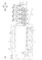
1.カラーレーザプリンタの全体構成
図1は、本発明の画像形成装置の一例としてのカラーレーザプリンタ(ドラムユニット:収容位置)の一実施形態を示す側断面図である。
1. 1 is a side sectional view showing an embodiment of a color laser printer (drum unit: accommodation position) as an example of an image forming apparatus of the present invention.
図2は、図1に示すカラーレーザプリンタ(ドラムユニット:引出位置)を示す側断面図である。 2 is a side sectional view showing the color laser printer (drum unit: drawing position) shown in FIG.
このカラーレーザプリンタ1は、横置きタイプのタンデム型カラーレーザプリンタであって、画像形成装置本体の一例としての本体ケーシング2内に、用紙Pを給紙するための給紙部3と、給紙された用紙Pに画像を形成するための画像形成部4とを備えている。
(1)本体ケーシング
本体ケーシング2は、画像形成部4を収容する側面視略矩形状のボックス状に形成されており、スキャナ部8(後述)と転写部10(後述)との間には、ドラムユニット12(後述)を収容するためのユニット収容部14が区画されている。また、本体ケーシング2の一方側壁には、ユニット収容部14に連通し、ドラムユニット12(後述)を着脱させるためのフロントカバー5が設けられている。
The
(1) Main Body Casing The
なお、以下の説明において、フロントカバー5が設けられる側(図1における右側)を前側とし、その反対側(図1における左側)を後側とする。また、カラーレーザプリンタ1を前側から見たときを左右の基準とする。すなわち、図1の紙面手前側が左側であり、紙面奥側が右側である。
(2)給紙部
給紙部3は、用紙Pを収容する給紙トレイ6を備えている。給紙トレイ6は、本体ケーシング2内の底部に着脱自在に装着されている。給紙トレイ6の前端部上方には、給紙ローラ7と、Uターンパスからなる給紙パス(図示せず)とが配置されている。
In the following description, the side where the
(2) Paper Feed Unit The
給紙ローラ7の回転により、給紙トレイ6に収容されている用紙Pが給紙パス(図示せず)に向けて1枚ずつ給紙される。その後、用紙Pは、給紙パス(図示せず)から、画像形成部4(感光体ドラム18(後述)と搬送ベルト24(後述)との間)に向けて搬送される。
(3)画像形成部
画像形成部4は、スキャナ部8、プロセス部9、転写部10、および定着部11を備えている。
(3−1)スキャナ部
スキャナ部8は、本体ケーシング2の上部に配置されている。スキャナ部8は、鎖線で示すように、4つの感光体ドラム18(後述)に向けて、画像データに基づくレーザビームをそれぞれ出射し、感光体ドラム18(後述)を露光する。
(3−2)プロセス部
プロセス部9は、スキャナ部8の下方であって、給紙部3の上方に配置されており、感光体ユニットの一例としての1つのドラムユニット12、および、各色に対応する4つの現像カートリッジ13を備えている。
The paper P stored in the paper feed tray 6 is fed one by one toward the paper feed path (not shown) by the rotation of the
(3) Image Forming Unit The
(3-1) Scanner Unit The
(3-2) Process Unit The process unit 9 is disposed below the
ドラムユニット12は、本体ケーシング2に対して前後方向にスライド可能であり、ユニット収容部14内に収容される収容位置(図1参照)と、ユニット収容部14から引き出される引出位置(図2参照)とに移動する。
The
現像カートリッジ13は、前後方向に沿って並列配置されるように、ドラムユニット12に対して着脱自在に装着されている。具体的には、前側から後側に向かって、ブラック現像カートリッジ13K、イエロー現像カートリッジ13Y、マゼンタ現像カートリッジ13Mおよびシアン現像カートリッジ13Cが、順次配置されている。
The developing
なお、ユニット収容部14の上端部には、その左右方向両端部において、現像カートリッジ13の取っ手31(後述)と当接するように、前後方向に沿って延び、ユニット収容部14の上面を形成するレール部15が設けられている。
Note that the upper end portion of the
レール部15は、最前方の現像カートリッジ13(具体的には、ブラック現像カートリッジ13K)の前端部から、最後方の現像カートリッジ13(具体的には、シアン現像カートリッジ13C)の後端部までの距離よりも長い前後方向長さに形成されている。また、その前端部は、前方に向かうにつれ上方に傾斜するように切欠かれている。
(3−2−1)ドラムユニット
ドラムユニット12は、左右1対のサイドフレーム16、両サイドフレーム16間に回転自在に支持される感光体ドラム18、両サイドフレーム16の間に架設されるセンタフレーム17、および、スコロトロン型帯電器19を備えている。
The
(3-2-1) Drum Unit The
両サイドフレーム16は、側面視矩形状に形成され、前端部間および後端部間に架設されるビームにより、左右方向に間隔を隔てて対向配置されている。 Both side frames 16 are formed in a rectangular shape in a side view, and are opposed to each other with a gap in the left-right direction by beams extending between front end portions and between rear end portions.
感光体ドラム18は、左右方向に沿って配置され、各色に対応するように、前後方向に沿って4つ並列配置されている。
The photoconductor drums 18 are arranged along the left-right direction, and four
センタフレーム17は、前方に向かうにつれ上方に傾斜する後端面を有するように、側面視略矩形状に形成されており、各感光体ドラム18に対応して、前後方向に沿って4つ並列配置されている。
The
スコロトロン型帯電器19は、感光体ドラム18の斜め後側上方に、感光体ドラム18と間隔を隔てて対向配置されるように、センタフレーム17に支持されている。
(3−2−2)現像カートリッジ
現像カートリッジ13は、各感光体ドラム18に対応して設けられており、それぞれ、感光体ドラム18に対向する下端部が開放される現像フレーム20と、供給ローラ(図示せず)、現像剤担持体の一例としての現像ローラ21および層厚規制ブレード(図示せず)を備えている。
The
(3-2-2) Developing Cartridge The developing
現像ローラ21は、現像フレーム20の下端部から露出するように、現像フレーム20の下端部に回転自在に支持されており、感光体ドラム18と接触するように配置されている。供給ローラ(図示せず)は、現像ローラ20の前側上方に配置され、層厚規制ブレード(図示せず)は、現像ローラ20の後側上方に配置されており、それらの上方の現像フレーム20内の空間には、各色に対応するトナーが収容されている。
(3−2−3)プロセス部での現像動作
現像カートリッジ13内のトナーは、供給ローラ(図示せず)に供給され、さらに、現像ローラ20に供給され、供給ローラ(図示せず)と現像ローラ20との間で正極性に摩擦帯電される。
The developing
(3-2-3) Developing operation in the process section The toner in the developing
現像ローラ20に供給されたトナーは、現像ローラ20の回転に伴って、層厚規制ブレード(図示せず)によって厚さが規制され、一定厚さの薄層として現像ローラ20の表面に担持される。
The toner supplied to the developing
一方、感光体ドラム18の表面は、感光体ドラム18の回転に伴って、スコロトロン型帯電器17により一様に正帯電された後、スキャナ部8からのレーザビーム(図1破線参照。)の高速走査により露光される。これにより、用紙Pに形成すべき画像に対応した静電潜像が感光体ドラム18の表面に形成される。
On the other hand, the surface of the
感光体ドラム18がさらに回転すると、現像ローラ20の表面に担持され、かつ、正帯電されているトナーが、感光体ドラム18の表面に形成されている静電潜像に供給される。これにより、感光体ドラム18の静電潜像は可視像化され、感光体ドラム18の表面には、反転現像によるトナー像が担持される。
(3−3)転写部
転写部10は、本体ケーシング2内において、給紙部3の上方であって、プロセス部9の下方において、前後方向に沿って配置されている。この転写部10は、駆動ローラ22、従動ローラ23、搬送ベルト24および転写ローラ25を備えている。
When the
(3-3) Transfer Unit The
駆動ローラ22および従動ローラ23は、前後方向に間隔を隔てて対向配置されており、それらの周りに搬送ベルト24が巻回されている。
The driving
転写ローラ25は、各感光体ドラム18と、搬送ベルト24を挟んで対向するように、それぞれ設けられている。
The
そして、給紙部3から給紙された用紙Pは、搬送ベルト24によって、前側から後側に向かって、各感光体ドラム18と各転写ローラ25とが対向する転写位置を順次通過するように搬送される。その搬送中に、各感光体ドラム18に担持されている各色のトナー像が、用紙Pに順次転写され、カラー画像が形成される。
(3−4)定着部
定着部11は、転写部10の後方に配置され、加熱ローラ26、および加熱ローラ26に対向する加圧ローラ27を備えている。転写部10において、用紙Pに転写されたカラー画像は、用紙Pが加熱ローラ26と加圧ローラ27との間を通過する間に、加熱および加圧されることによって用紙Pに熱定着される。
(4)排紙
トナー像が定着した用紙Pは、Uターンパスからなる排紙パス(図示せず)を通過して、排紙ローラ28に向けて搬送され、排紙ローラ28によって、本体ケーシング2の上面に形成された排紙トレイ29上に排紙される。
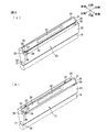
2.現像カートリッジ
図3は、図1に示す現像カートリッジの斜視図であって、(a)は、把持部材が第2位置にある状態を示し、(b)は、把持部材が第1位置にある状態を示す。
Then, the paper P fed from the
(3-4) Fixing Unit The fixing
(4) Paper discharge The paper P on which the toner image has been fixed passes through a paper discharge path (not shown) consisting of a U-turn path and is conveyed toward the
2. 3 is a perspective view of the developing cartridge shown in FIG. 1, in which (a) shows a state where the gripping member is in the second position, and (b) shows a state where the gripping member is in the first position. Indicates.
図4は、図3に対応する右側断面図であって、(a)は、把持部材が第2位置にある状態を示し、(b)は、把持部材が第1位置にある状態を示す。 4A and 4B are right side cross-sectional views corresponding to FIG. 3, in which FIG. 4A shows a state where the gripping member is in the second position, and FIG. 4B shows a state where the gripping member is in the first position.
現像カートリッジ13は、図3(a)に示すように、現像フレーム20、および、把持部材の一例としての取っ手31を備えている。
As shown in FIG. 3A, the developing
現像フレーム20は、上記したように、下端部に現像ローラ21を露出させる開口部32が形成される箱状に形成されている。
As described above, the developing
現像フレーム20は、その上端部において、端面の一例としての上端面33を有している。また、現像フレーム20の上端部には、ばね支持板34、および、鉤板35が設けられている。また、現像フレーム20の上端部には、その前端部において、側面視矩形状の切欠部36が形成されている。
The developing
上端面33は、現像カートリッジ13がドラムユニット12に装着されている状態において、図4(a)に示すように、平坦形状であり、前方に向かうに従って下方に傾斜している。
In the state where the developing
ばね支持板34は、上端面33の後端縁から、上斜め前方に向かって突出し、上端面33の左右全幅にわたって形成されている。また、ばね支持板34の前端面には、左右両端部において、第1付勢手段の一例としての引張ばね37が配置されている。
The
引張ばね37は、コイルばねであり、その後端部は、ばね支持板34に固定されている。
The
鉤板35は、上端面33の左右方向両端部から、上斜め前方に向かって延び、さらに、左右方向内方に屈曲している。鉤板35は、上端面33の後端縁から前後方向途中(切欠部36の手前)までにわたって形成されている。また、鉤板35は、左右方向内方に屈曲している部分において、前方に向かうに従って、厚みが薄くなるように、下面が上方に傾斜している。
The
そして、鉤板35の内側面は、上端面33とともにガイド溝38を区画している。
The inner surface of the
ガイド溝38は、上端面33の傾斜方向に沿って形成されており、その上端面33の傾斜方向と直交する方向の長さ(上下溝幅)が、前方に向かうに従って長くなるように形成されている。
The
切欠部36は、上端面33から、下斜め後方に向かって断面L字形状に切欠かれている。また、切欠部36の左右方向両端部には、第2付勢手段の一例としての当接部材39が配置されている。
The
各当接部材39は、圧縮ばね41と、圧縮ばね41を被覆するばね収容筒部40とを備えている。
Each
圧縮ばね41は、コイルばねであり、その下端部が上端面33に固定されている。
The
ばね収容筒部40は、断面円弧状の上蓋が一体的に形成されている円筒形状に形成されている。ばね収容筒部40は、圧縮ばね41の上端部から下端部に向けて、圧縮ばね41に被せられている。
The spring accommodating
そして、圧縮ばね41は、常には、ばね収容筒部40を、上斜め前方に向かって付勢している。
And the
取っ手31は、左右方向に沿って延びる略直角三角柱形状に形成されている。
The
すなわち、取っ手31の前端部は、上斜め前方に向かって突出する突出部51として形成されている。突出部51の後端面は、上方へ向かうに従って、前側に傾斜している。また、突出部51には、突出部51を前後方向に貫通する把持穴42が、左右方向に延びるように形成されている。
That is, the front end portion of the
また、取っ手31の左右方向両端には、上端面33の傾斜方向に沿って延びるとともに、左右方向外側に向かって突出する突条52が形成されている(図3(b)参照。)。また、上端面33と対向している取っ手31の下面には、その前端部において、前方に向かうに従い、上端面33との間隔が拡がるように上方に傾斜する傾斜面53が形成されている。
Further, at both ends of the
そして、取っ手31の突条52が、現像フレーム20のガイド溝38に、嵌合されると、取っ手31は、現像カートリッジ13の上端面33の上側において、上端面33の傾斜方向に沿って、前側の第1位置(図4(b)参照。)と、後側の第2位置(図4(a)参照。)との間をスライド自在に設けられる。
When the
また、取っ手31の後端部には、引張ばね37の前端部が連結される。これにより、取っ手31は、常には、第2位置側に向かって付勢される。
Further, the front end portion of the
取っ手31は、引張ばね37の付勢力に抗して第1位置に配置されるときには(図4(b)参照。)、傾斜面53において当接部材39と当接し、当接部材39を押圧する。また。取っ手31は、引張ばね37の付勢力により第2位置に配置されるときには(図4(a)参照。)、当接部材39との当接が解除され、当接部材39への押圧が解除される。
3.現像カートリッジの着脱動作
現像カートリッジ13を本体ケーシング2に装着するには、図2に示すように、まず、フロントカバー5を開放して、本体ケーシング2のユニット収容部14からドラムユニット12を収容位置(図1参照)から引出位置まで引き出す。
When the
3. Mounting and Demounting Operation of Developer Cartridge To attach the
そして、各現像カートリッジ13の取っ手31を把持し、上方からドラムユニット12の各色に対応する位置に挿入する。すると、現像ローラ21が感光体ドラム18に当接する位置において、現像カートリッジ13のドラムユニット12への挿入が、図示しない規制部材によって、弾性的に規制される。そして、取っ手31を離すと、現像カートリッジ13は、自重により前側に傾倒し、ドラムフレーム12の前壁に支持される。これにより、各現像カートリッジ13は、その上端面33がドラムユニット12のスライド方向(前後方向)の収容位置側(後側)から引出位置側(前側)に向けて徐々に下方に傾斜するように、装着される。
Then, the
このとき、各現像カートリッジ13の取っ手31は、引張ばね37の付勢力により、第2位置に配置されており、当接部材39との当接が解除されている。
At this time, the
そして、ドラムユニット12を前方から後方に向かって押し込み、引出位置から収容位置に向かってスライドさせる。
Then, the
すると、各現像カートリッジ13の取っ手21の突出部51の後側面が、ユニット収容部14のレール部15の前端部と当接する(図4(a)参照。)。
Then, the rear side surface of the protruding
次いで、さらにドラムユニット12を前方から後方に向かって押し込むと、取っ手31は、レール部15から前方に向かう反作用を受けることにより、レール部15と摺擦しながら、引張ばね37の付勢力に抗して、第2位置から第1位置に向かって、すなわち、下斜め前方に向かってスライドする。
Next, when the
同時に、取っ手31のスライドに伴い、取っ手31の傾斜面53が当接部材39と当接し、さらに当接部材39(圧縮ばね41の上蓋)に乗り上げて、圧縮ばね41の付勢力に抗して当接部材39を押圧する。
At the same time, as the
そして、さらにドラムユニット12を前方から後方に向かって押し込むと、取っ手31の突出部51が、レール部15の下方に潜り込んで、レール部15の下端縁と当接する(図4(b)参照。)。
When the
このとき、取っ手31は、第1位置に配置され、当接部材39を押圧する。そして、当接部材39は、現像フレーム20を感光体ドラム18に向けて付勢する。これにより、現像ローラ21が感光体ドラム18に対して、弾性的に圧接される。
At this time, the
そして、図1に示すように、ドラムユニット12を収容位置まで押し込むと、各現像カートリッジ13の取っ手31が全て第1位置に配置され、各現像ローラ21が対応する感光体ドラム18に対して圧接される。
As shown in FIG. 1, when the
これにより、現像カートリッジ13の本体ケーシング2への装着が完了する。
Thereby, the mounting of the developing
また、現像カートリッジ13を本体ケーシング2から取り外すには、まず、収容位置にあるドラムユニット12を前方に向かって引き出す。
In order to remove the developing
すると、各現像カートリッジ13は、順次、取っ手31とレール部15との当接が解除され、引張ばね37の付勢力によって、取っ手31が第1位置から第2位置へスライドする。
Then, in each developing
そして、図2に示すように、ドラムユニット12を引出位置まで引き出すと、各現像カートリッジ13の取っ手31が、引張ばね37の付勢力によって、第2位置に配置される。
As shown in FIG. 2, when the
このとき、各取っ手31の前方には、隣接する現像カートリッジ13との間に、当接部材39に相当する間隔が形成される。
At this time, an interval corresponding to the
次いで、隣接する現像カートリッジ13との間隔から把持穴42に手を入れて、そのまま取っ手31を把持し、現像カートリッジ13を取り外す。
Next, a hand is put into the holding hole 42 from the interval with the adjacent developing
これにより、現像カートリッジ13の本体ケーシング2からの離脱が完了する。
4.作用効果
(1)このカラーレーザプリンタ1によれば、図2に示すように、ドラムユニット12が引出位置にあるときに、ドラムユニット12に対して現像カートリッジ13を装着すると、その現像フレーム20の上端面33に配置される取っ手31は、引張ばね37の付勢力により、後側の第2位置に配置される。このとき、当接部材39は、前側の切欠部36に配置されているので、取っ手31との当接が解除されており、取っ手31からの押圧力を受けない。
Thereby, the separation of the developing
4). Operation and Effect (1) According to this
次いで、ドラムユニット12を、本体ケーシング2に対して引出位置から収容位置へスライド移動させると、レール部15に取っ手31が干渉し、取っ手31には第1位置側へ向かう押圧力が作用する。そのため、取っ手31は、引張ばね37の付勢力に抗して、現像フレーム20の上端面33の傾斜に沿って第1位置へスライドする。このとき、取っ手31は、レール部15との間の摺接により生じる摩擦により、第1位置へと移動する。
Next, when the
そして、図1に示すように、ドラムユニット12が収容位置に位置すると、取っ手31は、引張ばね37の付勢力に抗して、前側の第1位置に配置される。すると、取っ手18が当接部材39に乗り上げて、当接部材39は、取っ手18から押圧力を受けて、現像フレーム20を感光体ドラム18に向けて付勢する。これによって、ドラムユニット12が収容位置にあるときには、現像カートリッジ13の感光体ドラム18に対する、確実な圧接を確保することができる。
As shown in FIG. 1, when the
一方、ドラムユニット12を、本体ケーシング2に対して収容位置から引出位置へスライド移動させると、レール部15と取っ手31との干渉がなくなることにより、取っ手31には、引張ばね37により、第2位置側へ向かう付勢力が作用する。そのため、取っ手31は、引張ばね37の付勢力により、現像フレーム20の上端面33の傾斜に沿って第2位置へスライドする。
On the other hand, when the
そして、図2に示すように、ドラムユニット12が引出位置に位置すると、取っ手31は、引張ばね37の付勢力により第2位置に配置される。すると、当接部材39は、取っ手31との当接を解除され、取っ手31からの押圧力を受けない。これによって、感光体ユニット18が引出位置にあるときには、現像カートリッジ13の感光体ドラム18に対する、確実な圧接解除を確保することができる。
As shown in FIG. 2, when the
また、取っ手31が後側の第2位置に配置されると、隣接する各現像カートリッジ13の取っ手31の前方には、当接部材39が設けられている空間が形成される。そのため、その空間から把持穴42に手を入れて取っ手31をそのまま把持して、現像カートリッジ13を容易に離脱させることができる。また、取っ手31が第1位置より第2位置に位置した方が、取っ手31は、上方に位置するため、さらに、取っ手31を把持しやすくなる。
When the
このように、ドラムユニット12が収容位置にあるときには、現像カートリッジ13の感光体ドラム18に対する、確実な圧接を確保することができ、また、ドラムユニットが引出位置にあるときには、現像カートリッジ13の感光体ドラム18に対する、確実な圧接解除を確保することができる。さらに、ドラムユニット12が引出位置にあるときには、取っ手31をそのまま把持して、ドラムユニット12に対して現像カートリッジ13を容易に離脱させることができる。
(2)また、このカラーレーザプリンタ1によれば、図1に示すように、取っ手31の前端部には、ユニット収容部14のレール部15に向かって突出する突出部51が形成されている。
In this way, when the
(2) Further, according to the
そのため、突出部51において、取っ手31と、レール部15との確実な摺擦を図ることができる。しかも、突出部51は、取っ手31の前端部に形成されているので、取っ手31が第1位置に位置しているときには、当接部材39に対して、当接部材39の付勢方向上流側に配置される。そのため、取っ手31からの押圧力を当接部材39に確実に作用させることができ、現像カートリッジ13の感光体ドラム18に対する確実な圧接を図ることができる。
(3)また、このカラーレーザプリンタ1によれば、引張ばね37は、現像フレーム20の上端面33の前端部に形成される切欠部36に配置されている。
Therefore, in the protruding
(3) According to the
そのため、ドラムユニット12を引出位置から収容位置へスライド移動させたときに、第1位置側へ向かう取っ手31は、当接部材39(圧縮ばね41の上蓋)に容易に乗り上げることができる。
Therefore, when the
しかも、当接部材39は、切欠部36の左右方向両端に配置されている。
In addition, the abutting
そのため、当接部材39は、左右方向両端において、現像フレーム20を付勢することができる。その結果、現像カートリッジ13の感光体ドラム18に対する均一かつ安定した圧接を図ることができる。
(4)また、このカラーレーザプリンタ1によれば、取っ手31の左右方向両端には、突条52が形成されており、その突条52は、現像フレーム20の上端面33に沿って形成されるガイド溝38に、スライド自在に嵌合される。
Therefore, the
(4) According to the
そのため、取っ手31の第1位置と第2位置との間の確実なスライドを図ることができる。
Therefore, a reliable slide between the first position and the second position of the
しかも、ガイド溝38は、第2位置から第1位置に向けて、そのスライド方向と直交する上下方向の幅が拡がるように形成されている。
And the
そのため、取っ手31の突条52は、第1位置において、ガイド溝38に遊嵌される。これにより、取っ手31は、第1位置において、当接部材39を弾性的に押圧することができる。その結果、現像カートリッジ13を感光体ドラム18に対して適切な押圧力で圧接させることができる。
(5)また、このカラーレーザプリンタ1によれば、取っ手31の前端部には、現像フレーム20の上端面33との対向面に傾斜面53が形成されている。そして、その傾斜面53は、第1位置側に向かうに従って現像フレーム20の上端面33と取っ手31との間隔が拡がるように傾斜している。
Therefore, the
(5) According to the
そのため、感光体ユニット18を引出位置から収容位置へスライド移動させたときに、第1位置側へ向かう取っ手31は、当接部材39(圧縮ばね41の上蓋)に、さらに容易に乗り上げることができる。
Therefore, when the
その結果、取っ手31を、さらに容易に第1位置にスライドさせることができる。
(6)また、このカラーレーザプリンタ1によれば、引張ばね37は、現像フレーム20の上端面33の第2位置側に設けられている。
As a result, the
(6) According to the
そのため、簡易な構成で、取っ手31を第2位置に向けて常時付勢することができる。
Therefore, the
1 カラーレーザプリンタ
2 本体ケーシング
12 ドラムユニット
13 現像カートリッジ
14 ユニット収容部
18 感光体ドラム
20 現像フレーム
21 現像ローラ
31 取っ手
33 上端面
36 切欠部
37 引張ばね
38 ガイド溝
39 当接部材
51 突出部
52 突条
53 傾斜部
DESCRIPTION OF
Claims (9)
並列配置された複数の感光体ドラムを有し、前記装置本体に対して前記複数の感光体ドラムの並列方向に、収容位置と引出位置との間でスライド移動可能に構成される感光体ユニットと、
各前記感光体ドラムに対応して設けられ、前記感光体ユニットが前記引出位置にあるときに、前記感光体ユニットに対して着脱自在に構成される複数の現像カートリッジと、
上面を有し、前記感光体ユニットが前記収容位置にあるときに、前記感光体ユニットを収容するためのユニット収容部とを備え、
各前記現像カートリッジは、
前記ユニット収容部の上面に対向し、前記感光体ユニットのスライド方向の前記収容位置側から前記引出位置側に向けて徐々に前記上面との距離が大きくなるように傾斜する端面を有する筐体と、
前記筐体の端面と前記ユニット収容部の上面との間に設けられ、前記感光体ユニットが前記収容位置にあるときの第1位置と、前記感光体ユニットが引出位置にあるときの第2位置との間をスライド自在に構成される把持部材と、
前記把持部材を前記第2位置側に向かって付勢する第1付勢手段と、
前記筐体の前記端面の第1位置側に設けられ、前記把持部材が前記第1位置にあるときには、前記把持部材から押圧力を受けて前記筐体を前記感光体ドラムに向けて付勢し、前記把持部材が前記第2位置にあるときには、前記把持部材から押圧力を受けない位置にある第2付勢手段とを備えることを特徴とする、画像形成装置。 The device body;
A photosensitive unit having a plurality of photosensitive drums arranged in parallel and configured to be slidable between an accommodation position and a drawing position in a parallel direction of the plurality of photosensitive drums with respect to the apparatus main body; ,
A plurality of developing cartridges provided corresponding to each of the photosensitive drums and configured to be detachable from the photosensitive unit when the photosensitive unit is in the drawing position;
A unit housing portion for housing the photoconductor unit when the photoconductor unit is in the housing position.
Each of the developing cartridges
A housing having an end surface facing the upper surface of the unit housing portion and inclined so that the distance from the upper surface gradually increases from the housing position side in the sliding direction of the photoconductor unit toward the drawing position side; ,
A first position provided between the end surface of the casing and the upper surface of the unit housing portion, and a second position when the photoconductor unit is in the pull-out position. A gripping member configured to be slidable between, and
First biasing means for biasing the gripping member toward the second position;
Provided on the first position side of the end surface of the casing, and when the gripping member is in the first position, the casing is biased toward the photosensitive drum by receiving a pressing force from the gripping member. An image forming apparatus comprising: a second urging unit in a position not receiving a pressing force from the gripping member when the gripping member is in the second position.
前記第2付勢手段は、前記切欠部の前記感光体ドラムの軸方向両端に配置されていることを特徴とする、請求項1または2に記載の画像形成装置。 The end surface of the housing is formed with a notch at the first position side end,
3. The image forming apparatus according to claim 1, wherein the second urging unit is disposed at both ends of the cutout portion in the axial direction of the photosensitive drum. 4.
前記筐体の前記端面には、前記突条がスライド自在に嵌合され、前記第2位置側から前記第1位置側に向かうに従い、前記スライド方向と直交する方向の幅が拡がるように、ガイド溝が形成されていることを特徴とする、請求項1ないし3のいずれかに記載の画像形成装置。 At both ends in the axial direction of the photosensitive drum of the gripping member, ridges extending along the sliding direction and protruding outward are formed,
The ridge is slidably fitted to the end surface of the housing, and the width in the direction orthogonal to the sliding direction increases as it goes from the second position side to the first position side. The image forming apparatus according to claim 1, wherein a groove is formed.
前記筐体の他端側に回転自在に支持される現像剤担持体と、
前記筐体の前記端面に設けられ、前記端面の一端側の第1位置と前記端面の他端側の第2位置とをスライド自在に構成される把持部材と、
前記把持部材を第2位置側に向かって付勢する第1付勢部材と、
前記端面の前記第1位置側端部に設けられ、前記把持部材が前記第1位置にあるときには、前記把持部材から押圧力を受けて前記筐体を前記把持部材から前記現像剤担持体に向かう方向に付勢し、前記把持部材が前記第2位置にあるときには、前記把持部材から押圧力を受けない位置にある第2付勢部材とを備え、
前記把持部材は、前記第1位置に配置されているときには、前記筐体に対して前記把持部材から前記現像剤担持体に向かう方向に遊動可能に構成されていることを特徴とする、現像カートリッジ。 A housing having an end face on one end side;
A developer carrying member rotatably supported on the other end of the housing;
A gripping member provided on the end surface of the housing and configured to be slidable between a first position on one end side of the end surface and a second position on the other end side of the end surface;
A first biasing member that biases the gripping member toward the second position;
Provided at the end of the end surface on the first position side, when the gripping member is in the first position, the casing is moved from the gripping member toward the developer carrier by receiving a pressing force from the gripping member. Urging in the direction, and when the gripping member is in the second position, the second biasing member in a position not receiving a pressing force from the gripping member,
The developing cartridge is configured to be movable in a direction from the gripping member toward the developer carrying member with respect to the housing when the gripping member is disposed at the first position. .
前記筐体の前記端面には、前記突条がスライド自在に嵌合され、前記第2位置側から前記第1位置側に向かうに従い、前記スライド方向と直交する方向の幅が拡がるように、ガイド溝が形成されていることを特徴とする、請求項7に記載の現像カートリッジ。 At both ends of the gripping member in the axial direction of the developer carrier, ridges extending along the sliding direction and projecting outward are formed,
The ridge is slidably fitted to the end surface of the housing, and the width in the direction orthogonal to the sliding direction increases as it goes from the second position side to the first position side. The developing cartridge according to claim 7, wherein a groove is formed.
Priority Applications (1)
| Application Number | Priority Date | Filing Date | Title |
|---|---|---|---|
| JP2008250541A JP4998423B2 (en) | 2008-09-29 | 2008-09-29 | Image forming apparatus and developing cartridge |
Applications Claiming Priority (1)
| Application Number | Priority Date | Filing Date | Title |
|---|---|---|---|
| JP2008250541A JP4998423B2 (en) | 2008-09-29 | 2008-09-29 | Image forming apparatus and developing cartridge |
Publications (2)
| Publication Number | Publication Date |
|---|---|
| JP2010079205A true JP2010079205A (en) | 2010-04-08 |
| JP4998423B2 JP4998423B2 (en) | 2012-08-15 |
Family
ID=42209673
Family Applications (1)
| Application Number | Title | Priority Date | Filing Date |
|---|---|---|---|
| JP2008250541A Expired - Fee Related JP4998423B2 (en) | 2008-09-29 | 2008-09-29 | Image forming apparatus and developing cartridge |
Country Status (1)
| Country | Link |
|---|---|
| JP (1) | JP4998423B2 (en) |
Cited By (5)
| Publication number | Priority date | Publication date | Assignee | Title |
|---|---|---|---|---|
| US9471035B2 (en) * | 2014-08-08 | 2016-10-18 | Brother Kogyo Kabushiki Kaisha | Handle of drum cartridge and image forming apparatus including the same |
| WO2017158970A1 (en) * | 2016-03-15 | 2017-09-21 | ブラザー工業株式会社 | Development cartridge |
| JP2020056817A (en) * | 2018-09-28 | 2020-04-09 | ブラザー工業株式会社 | Drawer |
| CN111200983A (en) * | 2017-10-06 | 2020-05-26 | 奥林巴斯株式会社 | Medical device |
| CN113835318A (en) * | 2020-06-23 | 2021-12-24 | 京瓷办公信息系统株式会社 | Image forming apparatus with a toner supply device |
Citations (3)
| Publication number | Priority date | Publication date | Assignee | Title |
|---|---|---|---|---|
| JPH0540405A (en) * | 1991-08-06 | 1993-02-19 | Ricoh Co Ltd | Structure for attaching and dettaching developing device |
| JP2007256352A (en) * | 2006-03-20 | 2007-10-04 | Brother Ind Ltd | Image forming apparatus and developing cartridge |
| JP2007256351A (en) * | 2006-03-20 | 2007-10-04 | Brother Ind Ltd | Image forming apparatus and developing cartridge |
-
2008
- 2008-09-29 JP JP2008250541A patent/JP4998423B2/en not_active Expired - Fee Related
Patent Citations (3)
| Publication number | Priority date | Publication date | Assignee | Title |
|---|---|---|---|---|
| JPH0540405A (en) * | 1991-08-06 | 1993-02-19 | Ricoh Co Ltd | Structure for attaching and dettaching developing device |
| JP2007256352A (en) * | 2006-03-20 | 2007-10-04 | Brother Ind Ltd | Image forming apparatus and developing cartridge |
| JP2007256351A (en) * | 2006-03-20 | 2007-10-04 | Brother Ind Ltd | Image forming apparatus and developing cartridge |
Cited By (8)
| Publication number | Priority date | Publication date | Assignee | Title |
|---|---|---|---|---|
| US9471035B2 (en) * | 2014-08-08 | 2016-10-18 | Brother Kogyo Kabushiki Kaisha | Handle of drum cartridge and image forming apparatus including the same |
| WO2017158970A1 (en) * | 2016-03-15 | 2017-09-21 | ブラザー工業株式会社 | Development cartridge |
| US9971299B2 (en) | 2016-03-15 | 2018-05-15 | Brother Kogyo Kabushiki Kaisha | Developing cartridge provided with casing including pressure member |
| CN111200983A (en) * | 2017-10-06 | 2020-05-26 | 奥林巴斯株式会社 | Medical device |
| CN111200983B (en) * | 2017-10-06 | 2024-02-13 | 奥林巴斯株式会社 | Medical device |
| JP2020056817A (en) * | 2018-09-28 | 2020-04-09 | ブラザー工業株式会社 | Drawer |
| JP7215050B2 (en) | 2018-09-28 | 2023-01-31 | ブラザー工業株式会社 | drawer |
| CN113835318A (en) * | 2020-06-23 | 2021-12-24 | 京瓷办公信息系统株式会社 | Image forming apparatus with a toner supply device |
Also Published As
| Publication number | Publication date |
|---|---|
| JP4998423B2 (en) | 2012-08-15 |
Similar Documents
| Publication | Publication Date | Title |
|---|---|---|
| JP5071492B2 (en) | Image forming apparatus | |
| JP4730413B2 (en) | Image forming apparatus and process cartridge | |
| JP4968301B2 (en) | Image forming apparatus and tandem photoreceptor unit | |
| JP5127567B2 (en) | Process cartridge | |
| JP4869289B2 (en) | Process cartridge and electrophotographic image forming apparatus | |
| US7715755B2 (en) | Image forming apparatus and developing cartridge with deformable handle | |
| JP5056819B2 (en) | Developer cartridge | |
| JP5768530B2 (en) | Image forming apparatus | |
| US8160477B2 (en) | Process cartridge and image forming apparatus | |
| JP2007121983A (en) | Image-forming device and process cartridge | |
| US7983609B2 (en) | Image forming apparatus having collection box | |
| JP2012230136A (en) | Image forming apparatus | |
| JP2008145502A (en) | Image forming apparatus | |
| JP4998423B2 (en) | Image forming apparatus and developing cartridge | |
| JP4968352B2 (en) | Image forming apparatus | |
| JP2007065556A (en) | Image forming apparatus | |
| JP6036186B2 (en) | Image forming apparatus | |
| JP5862044B2 (en) | Developing unit, process unit, and image forming apparatus | |
| JP2010078687A (en) | Image forming apparatus | |
| JP5206778B2 (en) | Image forming apparatus | |
| JP2007047481A (en) | Image forming apparatus and developing unit used in the image forming apparatus | |
| JP5919851B2 (en) | Image forming apparatus | |
| JP5908434B2 (en) | Image forming apparatus | |
| JP5630297B2 (en) | Photoconductor unit | |
| JP5218574B2 (en) | Image forming apparatus and process cartridge |
Legal Events
| Date | Code | Title | Description |
|---|---|---|---|
| A977 | Report on retrieval |
Free format text: JAPANESE INTERMEDIATE CODE: A971007 Effective date: 20110815 |
|
| A131 | Notification of reasons for refusal |
Free format text: JAPANESE INTERMEDIATE CODE: A131 Effective date: 20110823 |
|
| A521 | Request for written amendment filed |
Free format text: JAPANESE INTERMEDIATE CODE: A523 Effective date: 20111020 |
|
| TRDD | Decision of grant or rejection written | ||
| A01 | Written decision to grant a patent or to grant a registration (utility model) |
Free format text: JAPANESE INTERMEDIATE CODE: A01 Effective date: 20120417 |
|
| A01 | Written decision to grant a patent or to grant a registration (utility model) |
Free format text: JAPANESE INTERMEDIATE CODE: A01 |
|
| A61 | First payment of annual fees (during grant procedure) |
Free format text: JAPANESE INTERMEDIATE CODE: A61 Effective date: 20120430 |
|
| R150 | Certificate of patent or registration of utility model |
Ref document number: 4998423 Country of ref document: JP Free format text: JAPANESE INTERMEDIATE CODE: R150 Free format text: JAPANESE INTERMEDIATE CODE: R150 |
|
| FPAY | Renewal fee payment (event date is renewal date of database) |
Free format text: PAYMENT UNTIL: 20150525 Year of fee payment: 3 |
|
| LAPS | Cancellation because of no payment of annual fees |