JP2010079119A - Display drive circuit - Google Patents
Display drive circuit Download PDFInfo
- Publication number
- JP2010079119A JP2010079119A JP2008249427A JP2008249427A JP2010079119A JP 2010079119 A JP2010079119 A JP 2010079119A JP 2008249427 A JP2008249427 A JP 2008249427A JP 2008249427 A JP2008249427 A JP 2008249427A JP 2010079119 A JP2010079119 A JP 2010079119A
- Authority
- JP
- Japan
- Prior art keywords
- color gamut
- saturation
- expansion coefficient
- saturation expansion
- gamut vertex
- Prior art date
- Legal status (The legal status is an assumption and is not a legal conclusion. Google has not performed a legal analysis and makes no representation as to the accuracy of the status listed.)
- Granted
Links
Images


Classifications
-
- G—PHYSICS
- G09—EDUCATION; CRYPTOGRAPHY; DISPLAY; ADVERTISING; SEALS
- G09G—ARRANGEMENTS OR CIRCUITS FOR CONTROL OF INDICATING DEVICES USING STATIC MEANS TO PRESENT VARIABLE INFORMATION
- G09G1/00—Control arrangements or circuits, of interest only in connection with cathode-ray tube indicators; General aspects or details, e.g. selection emphasis on particular characters, dashed line or dotted line generation; Preprocessing of data
- G09G1/002—Intensity circuits
-
- G—PHYSICS
- G09—EDUCATION; CRYPTOGRAPHY; DISPLAY; ADVERTISING; SEALS
- G09G—ARRANGEMENTS OR CIRCUITS FOR CONTROL OF INDICATING DEVICES USING STATIC MEANS TO PRESENT VARIABLE INFORMATION
- G09G3/00—Control arrangements or circuits, of interest only in connection with visual indicators other than cathode-ray tubes
- G09G3/20—Control arrangements or circuits, of interest only in connection with visual indicators other than cathode-ray tubes for presentation of an assembly of a number of characters, e.g. a page, by composing the assembly by combination of individual elements arranged in a matrix no fixed position being assigned to or needed to be assigned to the individual characters or partial characters
- G09G3/34—Control arrangements or circuits, of interest only in connection with visual indicators other than cathode-ray tubes for presentation of an assembly of a number of characters, e.g. a page, by composing the assembly by combination of individual elements arranged in a matrix no fixed position being assigned to or needed to be assigned to the individual characters or partial characters by control of light from an independent source
- G09G3/36—Control arrangements or circuits, of interest only in connection with visual indicators other than cathode-ray tubes for presentation of an assembly of a number of characters, e.g. a page, by composing the assembly by combination of individual elements arranged in a matrix no fixed position being assigned to or needed to be assigned to the individual characters or partial characters by control of light from an independent source using liquid crystals
- G09G3/3611—Control of matrices with row and column drivers
- G09G3/3648—Control of matrices with row and column drivers using an active matrix
- G09G3/3655—Details of drivers for counter electrodes, e.g. common electrodes for pixel capacitors or supplementary storage capacitors
-
- G—PHYSICS
- G09—EDUCATION; CRYPTOGRAPHY; DISPLAY; ADVERTISING; SEALS
- G09G—ARRANGEMENTS OR CIRCUITS FOR CONTROL OF INDICATING DEVICES USING STATIC MEANS TO PRESENT VARIABLE INFORMATION
- G09G5/00—Control arrangements or circuits for visual indicators common to cathode-ray tube indicators and other visual indicators
- G09G5/02—Control arrangements or circuits for visual indicators common to cathode-ray tube indicators and other visual indicators characterised by the way in which colour is displayed
- G09G5/04—Control arrangements or circuits for visual indicators common to cathode-ray tube indicators and other visual indicators characterised by the way in which colour is displayed using circuits for interfacing with colour displays
-
- G—PHYSICS
- G09—EDUCATION; CRYPTOGRAPHY; DISPLAY; ADVERTISING; SEALS
- G09G—ARRANGEMENTS OR CIRCUITS FOR CONTROL OF INDICATING DEVICES USING STATIC MEANS TO PRESENT VARIABLE INFORMATION
- G09G5/00—Control arrangements or circuits for visual indicators common to cathode-ray tube indicators and other visual indicators
- G09G5/02—Control arrangements or circuits for visual indicators common to cathode-ray tube indicators and other visual indicators characterised by the way in which colour is displayed
- G09G5/06—Control arrangements or circuits for visual indicators common to cathode-ray tube indicators and other visual indicators characterised by the way in which colour is displayed using colour palettes, e.g. look-up tables
-
- G—PHYSICS
- G09—EDUCATION; CRYPTOGRAPHY; DISPLAY; ADVERTISING; SEALS
- G09G—ARRANGEMENTS OR CIRCUITS FOR CONTROL OF INDICATING DEVICES USING STATIC MEANS TO PRESENT VARIABLE INFORMATION
- G09G2320/00—Control of display operating conditions
- G09G2320/02—Improving the quality of display appearance
- G09G2320/0242—Compensation of deficiencies in the appearance of colours
-
- G—PHYSICS
- G09—EDUCATION; CRYPTOGRAPHY; DISPLAY; ADVERTISING; SEALS
- G09G—ARRANGEMENTS OR CIRCUITS FOR CONTROL OF INDICATING DEVICES USING STATIC MEANS TO PRESENT VARIABLE INFORMATION
- G09G2340/00—Aspects of display data processing
- G09G2340/14—Solving problems related to the presentation of information to be displayed
- G09G2340/145—Solving problems related to the presentation of information to be displayed related to small screens
Abstract
Description
本発明は、入力された表示データに応じて液晶パネルを駆動可能な表示駆動回路に関する。 The present invention relates to a display drive circuit capable of driving a liquid crystal panel according to input display data.
表示駆動回路の一例として、液晶ディスプレイを駆動するための液晶駆動回路を挙げることができる。近年バッテリ動作の情報機器や、携帯電話などに小型の液晶ディスプレイが搭載されている。これら小型の液晶ディスプレイは、高精彩、低コスト、低電力などの要求が強い。これらを解決するため、カラーフィルタの通過域特性を大きくするなどの工夫により対応している。この副作用として、色情報を数値化したカラーモデルであるR,G,B各原色の色純度が落ち、結果として、液晶パネルとして表現できる色の範囲(色域)が狭くなるという副作用が生じる。そのため、小型の液晶ディスプレイは色表現力が低くなる傾向にある。 As an example of the display driving circuit, a liquid crystal driving circuit for driving a liquid crystal display can be given. In recent years, small liquid crystal displays are mounted on battery-operated information devices and mobile phones. These small liquid crystal displays are highly demanded of high definition, low cost, and low power. In order to solve these problems, measures are taken such as increasing the passband characteristics of the color filter. As a side effect, the color purity of each primary color of R, G, B, which is a color model in which color information is digitized, is lowered, and as a result, a side effect that a color range (color gamut) that can be expressed as a liquid crystal panel is narrowed occurs. For this reason, small liquid crystal displays tend to have low color expressive power.
そこで、液晶ディスプレイに表示するデータの彩度を強調することで、見かけ上色域を広げ、液晶パネルの表現力内で色表現力を向上させるという試みがなされている。例えば特許文献1のように、伸張後の彩度が飽和してしまうことによる、色つぶれなどを解決する技術が知られており、この技術を小型液晶パネルに応用することで、見かけ上色域を広げ、パネルの表現力内で色表現力を向上させることができる。
Therefore, an attempt has been made to enhance the color expression within the expressive power of the liquid crystal panel by apparently expanding the color gamut by emphasizing the saturation of data displayed on the liquid crystal display. For example, as in
しかし、本願発明者の検討によれば、液晶パネルによって使用しているカラーフィルタや液晶材料の特性が異なり、色域も異なったものとなるため、上記特許文献1に示した技術の適用だけでは、ターゲットとなる液晶パネルの色域の面積に応じて、彩度を伸張する度合いを補正することが困難であると考えられる。更に、同面積の色域であっても、R,G,B各色の特性が異なるため、その色特性に応じて彩度を伸張する度合いを補正することも、上記特許文献1に示した技術の適用だけでは困難であると考えられる。 However, according to the study of the present inventor, the characteristics of the color filter and the liquid crystal material used by the liquid crystal panel are different and the color gamut is also different. It is considered that it is difficult to correct the degree of extension of the saturation according to the area of the color gamut of the target liquid crystal panel. Further, since the characteristics of each color of R, G, and B are different even in the same color gamut, it is also possible to correct the degree of extending the saturation according to the color characteristics. It is thought that it is difficult to apply only.
本発明の目的は、液晶パネルの色域、又はR,G,Bの色特性に応じて彩度を伸張する度合いを制御可能な技術を提供することにある。 An object of the present invention is to provide a technique capable of controlling the degree of expansion of saturation according to the color gamut of a liquid crystal panel or the color characteristics of R, G, and B.
本発明の上記並びにその他の目的と新規な特徴は本明細書の記述及び添付図面から明らかになるであろう。 The above and other objects and novel features of the present invention will be apparent from the description of this specification and the accompanying drawings.
本願において開示される発明のうち代表的なものについて簡単に説明すれば下記のとおりである。 A representative one of the inventions disclosed in the present application will be briefly described as follows.
すなわち、表示駆動回路は、初期色域頂点座標を記憶可能な初期色域頂点座標記憶部と、ユーザ目標色域頂点座標を記憶可能なユーザ目標色域頂点座標記憶部と、上記初期色域頂点座標と上記ユーザ目標色域頂点座標とに基づいて彩度データの伸張係数を決定する彩度伸張係数決定部と、上記彩度伸張係数に基づいて上記表示データの彩度を伸張する伸張部とを含む。上記初期色域頂点座標と上記ユーザ目標色域頂点座標とに基づいて彩度データの伸張係数が決定され、それに基づいて上記表示データの彩度が伸張される。これによって、液晶パネルの色域に応じて彩度を伸張する度合いを制御することができる。 That is, the display driving circuit includes an initial color gamut vertex coordinate storage unit capable of storing an initial color gamut vertex coordinate, a user target color gamut vertex coordinate storage unit capable of storing a user target color gamut vertex coordinate, and the initial color gamut vertex A saturation expansion coefficient determination unit that determines the expansion coefficient of the saturation data based on the coordinates and the user target color gamut vertex coordinates; and an expansion unit that expands the saturation of the display data based on the saturation expansion coefficient. including. A saturation coefficient expansion coefficient is determined based on the initial color gamut vertex coordinates and the user target color gamut vertex coordinates, and the saturation of the display data is expanded based on the coefficient. This makes it possible to control the degree of extending the saturation according to the color gamut of the liquid crystal panel.
本願において開示される発明のうち代表的なものによって得られる効果を簡単に説明すれば下記の通りである。 The effects obtained by the representative ones of the inventions disclosed in the present application will be briefly described as follows.
すなわち、入力された表示データに応じて液晶パネルを駆動可能な表示駆動回路において、液晶パネルの色域、又はR,G,Bの色特性に応じて彩度を伸張する度合いを制御することができる。 That is, in a display driving circuit capable of driving a liquid crystal panel according to input display data, the degree of expansion of saturation can be controlled according to the color gamut of the liquid crystal panel or the color characteristics of R, G, and B. it can.
1.代表的な実施の形態
先ず、本願において開示される発明の代表的な実施の形態について概要を説明する。代表的な実施の形態についての概要説明で括弧を付して参照する図面の参照符号はそれが付された構成要素の概念に含まれるものを例示するに過ぎない。
1. Representative Embodiment First, an outline of a typical embodiment of the invention disclosed in the present application will be described. The reference numerals of the drawings referred to with parentheses in the outline description of the representative embodiments merely exemplify what are included in the concept of the components to which the reference numerals are attached.
〔1〕本発明の代表的な実施の形態に係る表示駆動回路(101)は、初期色域頂点座標を記憶可能な初期色域頂点座標記憶部(211)と、ユーザ目標色域頂点座標を記憶可能なユーザ目標色域頂点座標記憶部(212)と、上記初期色域頂点座標と上記ユーザ目標色域頂点座標とに基づいて彩度データの伸張係数を決定する彩度伸張係数決定部(210)と、上記彩度伸張係数に基づいて上記表示データの彩度を伸張する伸張部(206)とを含む。 [1] A display driving circuit (101) according to a typical embodiment of the present invention includes an initial color gamut vertex coordinate storage unit (211) capable of storing an initial color gamut vertex coordinate, and a user target color gamut vertex coordinate. A user target color gamut vertex coordinate storage unit (212) that can be stored, and a saturation expansion coefficient determination unit that determines the expansion coefficient of saturation data based on the initial color gamut vertex coordinates and the user target color gamut vertex coordinates ( 210) and an expansion unit (206) for expanding the saturation of the display data based on the saturation expansion coefficient.
上記の構成によれば、上記初期色域頂点座標と上記ユーザ目標色域頂点座標とに基づいて彩度データの伸張係数が決定され、それに基づいて上記表示データの彩度が伸張されるため、液晶パネルの色域に応じて彩度を伸張する度合いを制御することができる。 According to the above configuration, since the expansion coefficient of the saturation data is determined based on the initial color gamut vertex coordinates and the user target color gamut vertex coordinates, and the saturation of the display data is expanded based on the coefficient, The degree of extending the saturation can be controlled according to the color gamut of the liquid crystal panel.
〔2〕上記〔1〕において、上記彩度伸張係数決定部は、上記初期色域頂点座標から計算される色域と、上記ユーザ目標色域頂点座標から計算される色域との面積比に基づいて上記伸張係数を算出するように構成することができる。 [2] In the above [1], the saturation expansion coefficient determination unit sets an area ratio between a color gamut calculated from the initial color gamut vertex coordinates and a color gamut calculated from the user target color gamut vertex coordinates. Based on this, the expansion coefficient can be calculated.
〔3〕上記〔1〕において、上記彩度伸張係数決定部は、上記初期色域頂点座標から計算される色域と、上記ユーザ目標色域頂点座標から計算される色域との面積比の平方根とることで上記伸張係数を算出するように構成することができる。 [3] In the above [1], the saturation expansion coefficient determination unit determines an area ratio between a color gamut calculated from the initial color gamut vertex coordinates and a color gamut calculated from the user target color gamut vertex coordinates. The expansion coefficient can be calculated by taking the square root.
〔4〕上記表示駆動回路の外部から上記初期色域頂点座標記憶部及び上記ユーザ目標色域頂点座標記憶部への情報設定を可能とするインタフェース(102)を設けることができる。 [4] An interface (102) that enables information to be set to the initial color gamut vertex coordinate storage unit and the user target color gamut vertex coordinate storage unit from the outside of the display drive circuit can be provided.
〔5〕本発明の別の実施の形態に係る表示駆動回路(101)は、初期色域頂点座標を記憶可能な初期色域頂点座標記憶部(211)と、ユーザ目標色域頂点座標を記憶可能なユーザ目標色域頂点座標記憶部(212)と、上記初期色域頂点座標と上記ユーザ目標色域頂点座標とに基づいて、R,G,Bそれぞれの彩度伸張係数を決定するR,G,B彩度伸張係数決定部(501)と、上記R,G,Bそれぞれの彩度伸張係数の補間演算を行う彩度伸張係数補間部(503)と、上記彩度伸張係数補間部で補間された彩度伸張係数に基づいて、上記表示データの彩度を伸張する伸張部(206)とを含む。 [5] A display drive circuit (101) according to another embodiment of the present invention stores an initial color gamut vertex coordinate storage unit (211) capable of storing an initial color gamut vertex coordinate and a user target color gamut vertex coordinate. R, G, and B for determining a saturation expansion coefficient for each of R, G, and B based on a possible user target color gamut vertex coordinate storage unit (212) and the initial color gamut vertex coordinates and the user target color gamut vertex coordinates A G / B saturation expansion coefficient determination section (501), a saturation expansion coefficient interpolation section (503) for performing interpolation calculation of the R, G, and B saturation expansion coefficients, and the saturation expansion coefficient interpolation section. A decompression unit (206) for decompressing the saturation of the display data based on the interpolated saturation expansion coefficient.
上記の構成によれば、上記初期色域頂点座標と上記ユーザ目標色域頂点座標とに基づいて、R,G,Bそれぞれの彩度伸張係数が決定され、それに基づいて、上記R,G,Bそれぞれの彩度伸張係数の補間演算が行われるため、液晶パネルのR,G,Bの色特性に応じて彩度を伸張する度合いを制御することができる。 According to the above configuration, the saturation expansion coefficients of R, G, and B are determined based on the initial color gamut vertex coordinates and the user target color gamut vertex coordinates, and based on the R, G, B, the saturation expansion coefficients are determined. Since the interpolation calculation of the saturation expansion coefficient for each B is performed, the degree of saturation expansion can be controlled according to the R, G, B color characteristics of the liquid crystal panel.
〔6〕上記〔5〕において、上記R,G,B彩度伸張係数決定部は、上記初期色域頂点座標及び上記ユーザ目標色域頂点座において白色座標からの距離をR,G,B各値について求め、その比からR,G,Bそれぞれの彩度伸張係数を計算するように構成することができる。 [6] In the above [5], the R, G, B saturation expansion coefficient determining unit calculates the distance from the white coordinate in the initial color gamut vertex coordinates and the user target color gamut vertex coordinates for each of R, G, B. It is possible to obtain a value and calculate a saturation expansion coefficient for each of R, G, and B from the ratio.
〔7〕上記〔6〕において、上記彩度伸張係数補間部は、色相データに基づいて上記R,G,B彩度伸張係数を直線補間するように構成することができる。 [7] In the above [6], the saturation expansion coefficient interpolation unit can be configured to linearly interpolate the R, G, B saturation expansion coefficients based on hue data.
〔8〕上記〔5〕において、上記表示駆動回路の外部から上記初期色域頂点座標記憶部及び上記ユーザ目標色域頂点座標記憶部への情報設定を可能とするインタフェース(102)を設けることができる。 [8] In the above [5], an interface (102) that enables information setting to the initial color gamut vertex coordinate storage unit and the user target color gamut vertex coordinate storage unit from the outside of the display drive circuit is provided. it can.
〔9〕本発明の別の実施の形態に係る表示駆動回路(101)は、R,G,Bそれぞれの彩度伸張係数を記憶可能なR,G,B彩度伸張係数記憶部(1001)と、上記R,G,Bそれぞれの彩度伸張係数の補間演算を行う彩度伸張係数補間部(503)と、上記彩度伸張係数補間部で補間された彩度伸張係数に基づいて、上記表示データの彩度を伸張する伸張部(206)とを含む。 [9] The display drive circuit (101) according to another embodiment of the present invention includes an R, G, B saturation expansion coefficient storage unit (1001) capable of storing R, G, B saturation expansion coefficients. And a saturation expansion coefficient interpolation unit (503) that performs interpolation calculation of the saturation expansion coefficients of R, G, and B, and the saturation expansion coefficient interpolated by the saturation expansion coefficient interpolation unit, An expansion unit (206) for expanding the saturation of the display data.
上記の構成によれば、上記彩度伸張係数補間部で補間された彩度伸張係数に基づいて、上記表示データの彩度が伸張されるため、液晶パネルのR,G,Bの色特性に応じて彩度を伸張する度合いを制御することができる。 According to the above configuration, since the saturation of the display data is expanded based on the saturation expansion coefficient interpolated by the saturation expansion coefficient interpolation unit, the R, G, B color characteristics of the liquid crystal panel can be obtained. Accordingly, the degree of extending the saturation can be controlled.
〔10〕上記〔9〕において、上記彩度伸張係数補間部は、色相データに基づいて上記R,G,Bそれぞれの彩度伸張係数を直線補間するように構成することができる。 [10] In the above [9], the saturation expansion coefficient interpolation unit can be configured to linearly interpolate the R, G, and B saturation expansion coefficients based on hue data.
〔11〕上記〔9〕において、上記上記表示駆動回路の外部から上記R,G,B彩度伸張係数記憶部への情報設定を可能とするインタフェース(102)を設けることができる。 [11] In the above [9], an interface (102) capable of setting information to the R, G, B saturation expansion coefficient storage unit from the outside of the display driving circuit can be provided.
2.実施の形態の説明
次に、実施の形態について更に詳述する。
2. Next, the embodiment will be described in more detail.
尚、実施の形態を説明するための全図において、同一の部材には原則として同一の符号を付し、その繰り返しの説明は省略する。 Note that components having the same function are denoted by the same reference symbols throughout the drawings for describing the embodiment, and the repetitive description thereof will be omitted.
<実施の形態1>
図1には、本発明にかかる表示駆動回路の一例である液晶ドライバを含む液晶表示装置が示される。
<
FIG. 1 shows a liquid crystal display device including a liquid crystal driver which is an example of a display driving circuit according to the present invention.
図1に示される液晶表示装置100は、特に制限されないが、液晶ドライバ101、制御プロセッサ113、及び液晶パネル114を含む。液晶ドライバ101は、液晶パネルの駆動と制御を液晶ドライバで行う。制御プロセッサ113は、表示データを作成し、上記液晶ドライバへ101へ転送する。液晶パネル114は、液晶ドライバ101から液晶ソース信号110と、液晶ゲート信号及びコモン信号111を受け取り、画像表示を行う。バックライトモジュール115は、所望の明るさでバックライトを点灯して、液晶パネル114を照らす。これによって、液晶パネル114の表示を可視光として見ることができる。
The liquid
上記液晶ドライバ101は、特に制限されないが、システムインタフェース102、コントロールレジスタ103、彩度伸張回路104、グラフィックRAM(ランダム・アクセス・メモリ)105、ソース線駆動回路108、タイミング発生回路106、階調電圧生成回路107、及び液晶駆動レベル発生回路109を含み、公知の半導体集積回路製造技術により、単結晶シリコン基板などの一つの半導体基板に形成される。
The liquid crystal driver 101 is not particularly limited, but includes a
コントロールレジスタ103は、液晶ドライバ各所のコントロールを行うレジスタの集合である。システムインターフェース102は、コントロールレジスタ103への書き込みデータを含む各種データを液晶ドライバ101の外部から取り込み、それを内部ブロックへ供給する。彩度伸張回路104は、システムインターフェース102からの表示データを、後述する彩度伸張方法により彩度を伸張した表示データを生成し、グラフィックRAM105へ転送する。グラフィックRAM105は、彩度伸張回路104経由で表示データを受け取って蓄積し、ソース線駆動回路108へ表示データを受け渡すためのバッファの役割をしている。タイミング発生回路106は、コントロールレジスタ103の記憶情報に従って液晶ドライバ全体の動作タイミングを生成している。階調電圧生成回路107は、ソース線駆動回路108で使用する階調電圧を生成している。ソース線駆動回路108は、グラフィックRAM105から送信されてくる表示データを使用し、階調電圧生成回路107で作成した階調電圧の中から特定の電圧を選択し、液晶ソース信号110として外部に出力している。液晶駆動レベル発生回路109は、液晶の駆動に使用されるゲート信号及びコモン信号111を生成し、それを外部に出力する。
The
上記のように構成された液晶ドライバ101は、以下のように動作する。 The liquid crystal driver 101 configured as described above operates as follows.
システムインターフェース102を介し、外部から表示データを取り込み、彩度伸張回路104にて、後述する表示データ彩度の伸張処理を行い、グラフィックRAM105へ蓄積する。タイミング発生回路106でグラフィックRAMの読み出しタイミングを発生し、そのタイミングで表示データをソース線駆動回路108に転送する。そこでは、階調電圧生成回路107で生成した階調電圧から前述の表示データで電圧を選択し、液晶ソース信号110として液晶パネル114に送信する。また、タイミング発生回路106で作成したタイミングを使用し、液晶駆動レベル発生回路109で液晶ゲート信号及びコモン信号111を作成し、これも液晶パネル114へ送信する。
Display data is fetched from the outside via the
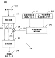
図2には、上記彩度伸張回路104の構成例が示される。
FIG. 2 shows a configuration example of the
図中201は抽出回路、202は表示データ、203は彩度データS、204は色相データH、205は明度データV、206は彩度伸張乗算器、207は合成回路、208は伸張後彩度データS'、209は彩度伸張係数k、210は彩度伸張係数演算回路、211は初期色域頂点座標レジスタ、212はユーザ目標色域頂点座標レジスタ、213は伸張後表示データである。初期色域頂点座標レジスタ211には、初期色域頂点座標が設定され、ユーザ目標色域頂点座標レジスタ212には、ユーザ目標色域頂点座標が設定される(図3参照)。初期色域頂点座標やユーザ目標色域頂点座標は、図示されない不揮発性メモリに格納されており、初期色域頂点座標レジスタ211やーザ目標色域頂点座標レジスタ212への座標情報の設定は、液晶表示装置100に電源が投入される毎に、システムインタフェース102を介して行われる。
In the figure, 201 is an extraction circuit, 202 is display data, 203 is saturation data S, 204 is hue data H, 205 is lightness data V, 206 is a saturation expansion multiplier, 207 is a synthesis circuit, and 208 is post-expansion saturation. Data S ′ and 209 are saturation expansion coefficient k, 210 is a saturation expansion coefficient arithmetic circuit, 211 is an initial color gamut vertex coordinate register, 212 is a user target color gamut vertex coordinate register, and 213 is display data after expansion. The initial color gamut vertex coordinate
抽出回路201は、システムインターフェース102から送信される表示データ202のR,G,B値をHSVやYCbCrに変換し、各パラメータを抽出する。HSVを用いた場合、彩度データ(S)203は、数1に示される式から算出され、0°以上、360°未満で表される色相データ(H)204は、数3に示される式から算出され、明度データ(V)205は、数4に示される式から算出される。彩度データ(S)203は、彩度伸張乗算器206に出力され、色相データ(H)204と明度データ(V)205は、合成回路207に出力される。
The
ただし、max(R,G,B)は、()内の最大値をとる関数、min(R,G,B)は、()内の最小値をとる関数である。 However, max (R, G, B) is a function that takes the maximum value in (), and min (R, G, B) is a function that takes the minimum value in ().
![]()
![]()

![]()
![]()
彩度伸張演算器206では、彩度データ(S)203を明度Vで正規化した値をnsとし、数4に示されるように、彩度伸張係数(k)209と乗算を行い、伸張後彩度データ(S’)208として、合成回路207に出力する。
In the
![]()
![]()
彩度伸張係数(k)209は、彩度伸張係数演算回路210から出力される。彩度伸張係数演算回路210は、初期色域頂点座標レジスタ211、ユーザ目標色域頂点座標レジスタ212から後述する方法を用いて、初期色域とユーザ目標色域の面積比より彩度伸張係数(k)209を計算する。初期色域頂点座標レジスタ211とユーザ目標色域座標レジスタ212の値は、色度図上のxy座標で表されている。設定方法は後述する。
The saturation expansion coefficient (k) 209 is output from the saturation expansion
合成回路207では、抽出回路201から出力される色相データ(H)204、明度データ(V)205と彩度伸張乗算器206から出力される伸張後彩度成分(S’)208を含むHSVデータを次に示す過程にてR,G,B値に変換し、それを伸張後表示データ213として出力する。
In the
まず、数5、数6に示されるように、色相Hを60で割り、0〜5の整数部Hiと小数部fに分離する。ただし、数5における括弧は、その内の値を越えない最大の整数値を意味する。 First, as shown in Equations 5 and 6, the hue H is divided by 60 and separated into an integer part Hi and a decimal part f of 0 to 5. However, the parentheses in Equation 5 mean the maximum integer value that does not exceed the value.
![]()
![]()
次に、数7に示されるように、伸張後彩度データS'と明度Vから、R,G,Bへの変換値を演算する。 Next, as shown in Equation 7, the converted values to R, G, and B are calculated from the post-expansion saturation data S ′ and the lightness V.
これらのブロックを使用し、彩度伸張回路104は、以下のように動作する。
Using these blocks, the
抽出回路201にて、表示データ202から彩度データ(S)203、色相データ(H)204、明度データ(V)205を抽出する。色相データ(H)204と明度データ(V)205は、合成回路207に出力される。
The
彩度データ(S)203は、彩度伸張乗算器206にて、彩度伸張係数(k)209との乗算され、伸張後彩度(S’)208として、合成回路207に出力される。彩度伸張係数(k)209は、彩度伸張係数演算回路210で、初期色域頂点座標レジスタ211とユーザ目標色域頂点座標レジスタ212の値から演算される。合成回路207は、入力されたHSV値をR,G,B値に変換後に、伸張後表示データ213として、図1に示されるグラフィックRAM105に出力する。
The saturation data (S) 203 is multiplied by the saturation expansion coefficient (k) 209 by the
図3には、初期色域頂点座標レジスタ211とユーザ目標色域頂点座標レジスタ212の設定値が示される。
FIG. 3 shows setting values of the initial color gamut vertex coordinate
301は初期色域、302はユーザ目標色域を表している。301の初期色域は、表示データを処理することなく出力した場合の色域であり、302のユーザ目標色域は、ユーザが目標とする色域である。これらの色域は図3に示されるように、R,G,Bの値を頂点とした三角形で表され、頂点の座標から面積を算出することができる。301の初期色域のR,G,B値における座標を初期色域頂点座標レジスタ211の設定値とし、302のユーザ目標色域のR,G,B値における座標をユーザ目標色域座標レジスタ212の設定値とする。
図4には、彩度伸張係数演算回路210における、彩度伸張係数の演算フローが示される。
FIG. 4 shows a calculation flow of the saturation expansion coefficient in the saturation expansion
まず、ステップ401では、初期色域頂点座標レジスタ211とユーザ目標色域座標レジスタ212に格納されている座標値より、それぞれの色域面積を算出する。次にステップ402では、彩度伸張係数(k)209を前述401で算出した面積を基に数9に示される式によって算出する。
First, in
上記例によれば、以下の作用効果を得ることができる。 According to the above example, the following operational effects can be obtained.
(1)液晶パネル114としての色域としては、図3の301に示した領域から拡張することは不可能であるが、301の領域内では低彩度から中彩度の画素について302の色域を持つように振る舞い、見かけ上、色域が302に拡張する効果を得られる。しかも、上記初期色域頂点座標と上記ユーザ目標色域頂点座標とに基づいて彩度データの伸張係数が決定され、それに基づいて上記表示データの彩度が伸張されるため、液晶パネル114の色域に応じて彩度を伸張する度合いを制御することができる。
(1) The color gamut of the
(2)上記(1)の作用効果により、パネルごとの色域に応じた彩度調整が可能となるため、液晶パネルにおいて低階調データで発生するブルーシフト現象についても、補正することが可能となる。 (2) Since the effect of (1) above enables saturation adjustment according to the color gamut of each panel, it is possible to correct the blue shift phenomenon that occurs in the low gradation data in the liquid crystal panel. It becomes.
<実施の形態2>
図5には、上記彩度伸張回路104の別の構成例が示される。
<
FIG. 5 shows another configuration example of the
図5に示される彩度伸張回路104が、図2に示されるのと大きく相違するのは、彩度伸張係数演算回路210に代えてR,G,B彩度伸張係数演算回路501が設けられ、さらに表示データ202から抽出した色相データ(H)204の値に基づいてR,G,B彩度伸張係数(kR,kG,kB)502を補間する彩度伸張係数補間回路503が設けられている点である。
The
R,G,B彩度伸張係数演算回路501は、初期色域頂点座標レジスタ211、ユーザ目標色域頂点座標レジスタ212から後述する方法を用いて、白の座標からR,G,Bの各頂点座標までの距離と、白の座標からR,G,Bの各頂点座標までの距離の比からR,G,B彩度伸張係数(kR,kG,kB)502を計算する。このR,G,B彩度伸張係数502は、R(H=0°)、G(H=120°)、B(H=240°)時における、彩度伸張係数kを計算したものである。
The R, G, B saturation expansion
彩度伸張補間回路503は、R,G,B彩度伸張数演算回路501にて算出されたR,G,B彩度伸張係数502を色相について直線補間し、各色相における彩度伸張係数kを算出し、彩度伸張係数演算器206に出力する。算出方法は後述する。
The saturation
図6には、上記R,G,B彩度伸張係数演算回路501における、R,G,B彩度伸張係数502の計算フローが示される。
FIG. 6 shows a calculation flow of the R, G, B
まず、ステップ601では、初期色域頂点座標レジスタ211に格納されている初期色域頂点座標値と、ユーザ目標色域頂点座標レジスタ212に格納されている、ユーザ目標色域頂点座標値から、R,G,Bそれぞれの彩度値を、数10に示される式により算出する。ただし、(x,y)は彩度を求めたい色座標のxy座標値、(x0,y0)は色域中、白色のxy座標値を表す。
First, in
![]()
![]()
次に、ステップ602では、初期色域におけるR,G,Bの各彩度値とユーザ目標色域におけるR,G,Bの各彩度値の比からR,G,B彩度伸張係数(kR,kG,kB)502を算出する。
Next, in
図7には、彩度伸張係数補間回路503の構成例が示される。
FIG. 7 shows a configuration example of the saturation expansion
701は色相データ除算器、702は区間判定値(hi)、703は直線補間係数(hf)、704はR,G,B彩度伸張係数テーブル、705は色相始点a、706は色相終点b、707は直線補間演算器である。
701 is a hue data divider, 702 is a section determination value (hi), 703 is a linear interpolation coefficient (hf), 704 is an R, G, B saturation expansion coefficient table, 705 is a hue start point a, 706 is a hue end point b,
色相データ除算器701には、抽出回路201より、色相データ(H)204が入力される。この色相データ(H)204を120で割り、その解の整数部を区間判定値(hi)702として、R,G,B彩度伸張テーブル704に出力し、小数部を直線補間係数(hf)703として直線補間演算器707に出力する。
Hue data (H) 204 is input from the
R,G,B彩度伸張係数テーブル704には、R,G,B彩度伸張係数演算回路501からR,G,B彩度伸張係数502と、色相データ除算器701から区間判定値(hi)702が入力される。その後、数11に示されるように、色相始点(a)705と色相終点(b)706を決定し、直線補間演算器707へ出力する。
The R, G, B saturation expansion coefficient table 704 includes an R, G, B saturation expansion coefficient
直線補間演算器707には、色相データ除算器701から直線補間係数(hf)703と、R,G,B彩度伸張係数テーブル704から色相始点(a)705と色相終点(b)706が送信される。これらを数12に示されるように直線補間することで、任意の色相データHにおける彩度伸張係数(k)209を算出し、それを彩度伸張乗算器206に出力する。
The
![]()
![]()
図8には、彩度伸張係数補間回路503により直線補間を実施し、各色相における彩度伸張係数(k)209の演算結果をグラフ化したものが示される。
FIG. 8 shows a graph of the calculation result of the saturation expansion coefficient (k) 209 in each hue after linear interpolation is performed by the saturation expansion
初期色域が歪んだ形状をしていても、上記伸張処理により、その形を見かけ上矯正することができる。しかも、上記初期色域頂点座標と上記ユーザ目標色域頂点座標とに基づいて彩度データの伸張係数が決定され、それに基づいて上記表示データの彩度が伸張されるため、R,G,Bの色特性に応じて彩度を伸張する度合いを制御することができる。また、本例では、直線補間されることで、伸張係数kの変化が滑らかになるため、良好な彩度伸張を行うことができる。 Even if the initial color gamut has a distorted shape, the shape can be apparently corrected by the stretching process. In addition, since the expansion coefficient of the saturation data is determined based on the initial color gamut vertex coordinates and the user target color gamut vertex coordinates, and the saturation of the display data is expanded based on the expansion coefficient, R, G, B The degree of extension of the saturation can be controlled according to the color characteristics. Further, in this example, since the change of the expansion coefficient k becomes smooth by performing linear interpolation, it is possible to perform satisfactory saturation expansion.
図9には、彩度伸張演算器206において、図8に示すような、各色相における彩度伸張係数(k)209と、彩度データ(S)203を乗算し、出力される伸張後彩度データ(S’)208を各色相についてグラフ化したものが示される。このように、ある一定の彩度Sをもつ、表示データを様々な色相Hで伸張し、伸張後表示データを計測し、伸張後彩度データ(S’)を求めることで、本方式を使用している事を明確にすることが可能となる。
In FIG. 9, the
<実施の形態3>
図10には、上記彩度伸張回路104の別の構成例が示される。
<Embodiment 3>
FIG. 10 shows another configuration example of the
図10に示される彩度伸張回路104が、図5に示されるのと大きく相違するのは、初期色域頂点座標レジスタ211、ユーザ目標色域頂点座標レジスタ212、及びR,G,B彩度伸張数演算回路501に代えて、R,G,B彩度伸張レジスタ1001が設けられている点である。
The
R,G,B彩度伸張レジスタ1001の値として、例えば図6に示されるフローチャートに従って算出されたR,G,B彩度伸張係数が設定される。算出されたR,G,B彩度伸張係数は、図示されない不揮発性メモリに格納され、液晶表示装置100に電源が投入される毎に、システムインタフェース102を介してR,G,B彩度伸張係数レジスタ1001に転送されるように構成することができる。これにより、初期色域頂点座標レジスタ211と、ユーザ目標色域頂点座標レジスタ212に代えてR,G,B彩度伸張レジスタ1001を使用することで、実施の形態2の場合と同一の効果を得ることができる。また、本例の場合、初期色域頂点座標レジスタ211、ユーザ目標色域頂点座標レジスタ212、及びR,G,B彩度伸張数演算回路501が不要とされるため、その分、ハードウェア構成の簡略化を図ることができる。
As a value of the R, G, B
以上本発明者によってなされた発明を具体的に説明したが、本発明はそれに限定されるものではなく、その要旨を逸脱しない範囲で種々変更可能であることはいうまでもない。 Although the invention made by the present inventor has been specifically described above, the present invention is not limited thereto, and it goes without saying that various changes can be made without departing from the scope of the invention.
例えば、上記の構成例では、初期色域頂点座標レジスタ211、ユーザ目標色域頂点座標レジスタ212、あるいはR,G,B彩度伸張係数レジスタ1001を彩度伸張回路104内に設けるようにしたが、それに代えてコントロールレジスタ103の一部を使用するようにしても良い。
For example, in the above configuration example, the initial color gamut vertex coordinate
以上の説明では主として本発明者によってなされた発明をその背景となった利用分野である液晶ドライバに適用した場合について説明したが、本発明はそれに限定されるものではなく、各種表示駆動回路に適用することができる。 In the above description, the case where the invention made by the present inventor is applied to the liquid crystal driver which is the field of use behind the invention has been described. However, the present invention is not limited to this and is applied to various display driving circuits. can do.
100 液晶表示装置
101 液晶ドライバ
102 システムインターフェース
103 コントロールレジスタ
104 彩度伸張部
105 グラフィックRAM
106 タイミング発生回路
107 階調電圧生成回路
108 ソース線駆動回路
109 液晶駆動レベル発生回路
110 液晶ソース信号
111 液晶ゲート信号、コモン信号
112 バックライト電源線
113 制御プロセッサ
114 液晶パネル
115 バックライトモジュール
201 抽出回路
202 表示データ
203 彩度データ(S)
204 色相データ(H)
205 明度データ(V)
206 彩度伸張乗算器
207 合成回路
208 伸張後彩度データ(S')
209 彩度伸張係数(k)
210 彩度伸張演算回路
211 初期色域頂点座標レジスタ
212 ユーザ目標色域頂点座標レジスタ
213 伸張後表示データ
301 初期色域
302 ユーザ目標色域
501 R,G,B彩度伸張係数演算回路
502 R,G,B彩度伸張係数(kR,kG,kB)
503 彩度伸張補間回路
701 色相データ除算器
702 区間判定地(hi)
703 直線補間係数(hf)
704 R,G,B彩度伸張係数テーブル
705 色相始点(a)
706 色相終点(b)
707 直線補間演算器
1001 R,G,B彩度伸張係数レジスタ
DESCRIPTION OF
106
204 Hue data (H)
205 Lightness data (V)
206
209 Saturation expansion coefficient (k)
210 Saturation
503 Saturation
703 Linear interpolation coefficient (hf)
704 R, G, B saturation expansion coefficient table 705 Hue start point (a)
706 Hue end point (b)
707 Linear interpolation calculator 1001 R, G, B saturation expansion coefficient register
Claims (11)
初期色域頂点座標を記憶可能な初期色域頂点座標記憶部と、
ユーザ目標色域頂点座標を記憶可能なユーザ目標色域頂点座標記憶部と、
上記初期色域頂点座標と上記ユーザ目標色域頂点座標とに基づいて彩度データの伸張係数を決定する彩度伸張係数決定部と、
上記彩度伸張係数に基づいて上記表示データの彩度を伸張する伸張部と、を含むことを特徴とする表示駆動回路。 A display drive circuit capable of driving a liquid crystal panel according to input display data,
An initial color gamut vertex coordinate storage unit capable of storing initial color gamut vertex coordinates;
A user target color gamut vertex coordinate storage unit capable of storing user target color gamut vertex coordinates;
A saturation expansion coefficient determining unit that determines an expansion coefficient of saturation data based on the initial color gamut vertex coordinates and the user target color gamut vertex coordinates;
And a decompression unit that decompresses the saturation of the display data based on the saturation expansion coefficient.
初期色域頂点座標を記憶可能な初期色域頂点座標記憶部と、
ユーザ目標色域頂点座標を記憶可能なユーザ目標色域頂点座標記憶部と、
上記初期色域頂点座標と上記ユーザ目標色域頂点座標とに基づいて、R,G,Bそれぞれの彩度伸張係数を決定するR,G,B彩度伸張係数決定部と、
上記R,G,Bそれぞれの彩度伸張係数の補間演算を行う彩度伸張係数補間部と、
上記彩度伸張係数補間部で補間された彩度伸張係数に基づいて、上記表示データの彩度を伸張する伸張部と、を含むことを特徴とする表示駆動回路。 A display drive circuit capable of driving a liquid crystal panel according to input display data,
An initial color gamut vertex coordinate storage unit capable of storing initial color gamut vertex coordinates;
A user target color gamut vertex coordinate storage unit capable of storing user target color gamut vertex coordinates;
An R, G, B saturation expansion coefficient determination unit for determining saturation expansion coefficients of R, G, B based on the initial color gamut vertex coordinates and the user target color gamut vertex coordinates;
A saturation expansion coefficient interpolation unit that performs interpolation calculation of the saturation expansion coefficients of R, G, and B;
And a decompression unit that decompresses the saturation of the display data based on the saturation expansion coefficient interpolated by the saturation expansion coefficient interpolation unit.
R,G,Bそれぞれの彩度伸張係数を記憶可能なR,G,B彩度伸張係数記憶部と、
上記R,G,Bそれぞれの彩度伸張係数の補間演算を行う彩度伸張係数補間部と、
上記彩度伸張係数補間部で補間された彩度伸張係数に基づいて、上記表示データの彩度を伸張する伸張部と、を含むことを特徴とする表示駆動回路。 A display drive circuit capable of driving a liquid crystal panel according to input display data,
An R, G, B saturation expansion coefficient storage section capable of storing R, G, B saturation expansion coefficients;
A saturation expansion coefficient interpolation unit that performs interpolation calculation of the saturation expansion coefficients of R, G, and B;
And a decompression unit that decompresses the saturation of the display data based on the saturation expansion coefficient interpolated by the saturation expansion coefficient interpolation unit.
Priority Applications (6)
| Application Number | Priority Date | Filing Date | Title |
|---|---|---|---|
| JP2008249427A JP5177751B2 (en) | 2008-09-29 | 2008-09-29 | Display drive circuit |
| CN2009101322904A CN101714340B (en) | 2008-09-29 | 2009-04-30 | Display drive circuit |
| US12/468,345 US8154560B2 (en) | 2008-09-29 | 2009-05-19 | Display drive circuit |
| US13/423,315 US8345072B2 (en) | 2008-09-29 | 2012-03-19 | Display system |
| US13/684,676 US8633951B2 (en) | 2008-09-29 | 2012-11-26 | Display system |
| US14/138,190 US9583030B2 (en) | 2008-09-29 | 2013-12-23 | Display system |
Applications Claiming Priority (1)
| Application Number | Priority Date | Filing Date | Title |
|---|---|---|---|
| JP2008249427A JP5177751B2 (en) | 2008-09-29 | 2008-09-29 | Display drive circuit |
Related Child Applications (1)
| Application Number | Title | Priority Date | Filing Date |
|---|---|---|---|
| JP2012268150A Division JP5401596B2 (en) | 2012-12-07 | 2012-12-07 | Display drive circuit |
Publications (3)
| Publication Number | Publication Date |
|---|---|
| JP2010079119A true JP2010079119A (en) | 2010-04-08 |
| JP2010079119A5 JP2010079119A5 (en) | 2011-11-10 |
| JP5177751B2 JP5177751B2 (en) | 2013-04-10 |
Family
ID=42056942
Family Applications (1)
| Application Number | Title | Priority Date | Filing Date |
|---|---|---|---|
| JP2008249427A Expired - Fee Related JP5177751B2 (en) | 2008-09-29 | 2008-09-29 | Display drive circuit |
Country Status (3)
| Country | Link |
|---|---|
| US (4) | US8154560B2 (en) |
| JP (1) | JP5177751B2 (en) |
| CN (1) | CN101714340B (en) |
Cited By (5)
| Publication number | Priority date | Publication date | Assignee | Title |
|---|---|---|---|---|
| US9691347B2 (en) | 2014-02-10 | 2017-06-27 | Synaptics Japan Gk | Image processing apparatus, image processing method, display panel driver and display apparatus |
| JP2017532799A (en) * | 2014-08-12 | 2017-11-02 | 深▲セン▼市華星光電技術有限公司 | Method for improving the saturation of WRGB |
| JP2017211601A (en) * | 2016-05-27 | 2017-11-30 | シナプティクス・ジャパン合同会社 | Chromatic adjustment circuit, display driver, and display device |
| US9837045B2 (en) | 2014-07-29 | 2017-12-05 | Synaptics Japan Gk | Device and method for color adjustment and gamma correction and display panel driver using the same |
| WO2020207168A1 (en) * | 2019-04-08 | 2020-10-15 | 重庆惠科金渝光电科技有限公司 | Method and system for driving display module, and display device |
Families Citing this family (13)
| Publication number | Priority date | Publication date | Assignee | Title |
|---|---|---|---|---|
| JP5177751B2 (en) * | 2008-09-29 | 2013-04-10 | ルネサスエレクトロニクス株式会社 | Display drive circuit |
| KR101332514B1 (en) * | 2010-12-27 | 2013-11-22 | 엘지디스플레이 주식회사 | Gamma Setting Method for Display Device |
| CN102646398B (en) * | 2011-05-19 | 2013-11-27 | 京东方科技集团股份有限公司 | Image display method and device |
| WO2015058877A1 (en) * | 2013-10-23 | 2015-04-30 | Thomson Licensing | Method and apparatus for mapping the colors of an image according to the content of this image |
| CN104732952B (en) * | 2013-12-23 | 2017-08-11 | 昆山国显光电有限公司 | Color displays processing method and system |
| JP6360321B2 (en) | 2014-02-10 | 2018-07-18 | シナプティクス・ジャパン合同会社 | Display device, display panel driver, image processing device, and image processing method |
| EP3115250B1 (en) * | 2014-03-07 | 2020-07-15 | The University of Tokyo | In-wheel motor system |
| JP6229625B2 (en) * | 2014-09-24 | 2017-11-15 | 株式会社Jvcケンウッド | Color gamut conversion apparatus, color gamut conversion method, and color gamut conversion program |
| EP3226203A1 (en) | 2016-03-30 | 2017-10-04 | Thomson Licensing | Method for detection of saturated pixels in an image |
| CN107742507B (en) * | 2017-10-31 | 2019-11-22 | 武汉华星光电技术有限公司 | Improve the method and system of display color gamut |
| US11475854B2 (en) * | 2018-12-11 | 2022-10-18 | HKC Corporation Limited | Driving method of display module, driving system thereof, and display device |
| WO2020118926A1 (en) * | 2018-12-11 | 2020-06-18 | 惠科股份有限公司 | Display panel driving method, driving system, and display device |
| CN111653232B (en) * | 2020-06-05 | 2021-11-16 | 广州视源电子科技股份有限公司 | LED screen color gamut calibration method and device |
Citations (4)
| Publication number | Priority date | Publication date | Assignee | Title |
|---|---|---|---|---|
| JP2004096731A (en) * | 2002-07-20 | 2004-03-25 | Samsung Electronics Co Ltd | Method and apparatus of improving adaptive coloration in colored image |
| WO2007132635A1 (en) * | 2006-05-15 | 2007-11-22 | Sharp Kabushiki Kaisha | Color image display device and color conversion device |
| JP2008104177A (en) * | 2006-10-17 | 2008-05-01 | Samsung Electronics Co Ltd | Apparatus and method of improving viewability of image |
| JP2008165231A (en) * | 2007-01-04 | 2008-07-17 | Samsung Electronics Co Ltd | Apparatus and method for correcting ambient light adaptive color |
Family Cites Families (28)
| Publication number | Priority date | Publication date | Assignee | Title |
|---|---|---|---|---|
| JPH0264875A (en) | 1988-08-31 | 1990-03-05 | Toshiba Corp | High speed chroma converter for color picture |
| BE1004659A5 (en) * | 1991-03-01 | 1993-01-05 | Barco Graphics Nv | METHOD AND APPARATUS FOR transforming a KLEURCOORDINATENSET. |
| US5185661A (en) * | 1991-09-19 | 1993-02-09 | Eastman Kodak Company | Input scanner color mapping and input/output color gamut transformation |
| US5319473A (en) * | 1991-11-27 | 1994-06-07 | Xerox Corporation | Methods and apparatus for performing real time color gamut compressions |
| JP3548589B2 (en) * | 1993-04-30 | 2004-07-28 | 富士通株式会社 | Output device color reproduction method and device |
| JP3423413B2 (en) * | 1994-06-21 | 2003-07-07 | キヤノン株式会社 | Handwritten information recognition apparatus and method |
| JP3583630B2 (en) * | 1998-11-30 | 2004-11-04 | 富士通株式会社 | Color data conversion method |
| JP3830747B2 (en) * | 2000-10-10 | 2006-10-11 | 三菱電機株式会社 | Color reproduction range compression method and color reproduction range compression apparatus |
| WO2002099557A2 (en) * | 2001-06-07 | 2002-12-12 | Genoa Technologies Ltd. | System and method of data conversion for wide gamut displays |
| JP4110408B2 (en) | 2001-06-26 | 2008-07-02 | セイコーエプソン株式会社 | Image display system, projector, image processing method, and information storage medium |
| JP3888176B2 (en) * | 2002-02-15 | 2007-02-28 | 三菱電機株式会社 | Color conversion apparatus and color conversion method |
| JP3719424B2 (en) | 2002-05-09 | 2005-11-24 | セイコーエプソン株式会社 | Image processing system, projector, image processing method, program, and information storage medium |
| KR20040055060A (en) * | 2002-12-20 | 2004-06-26 | 삼성전자주식회사 | Color signal processing device and a method thereof |
| WO2005048583A1 (en) * | 2003-11-14 | 2005-05-26 | Mitsubishi Denki Kabushiki Kaisha | Color correction device and color correction method |
| US8026953B2 (en) * | 2004-05-11 | 2011-09-27 | Samsung Electronics Co., Ltd. | Method for processing color image data |
| KR100601867B1 (en) * | 2004-06-11 | 2006-07-19 | 삼성전자주식회사 | Gamut mapping apparatus using vetcor streching and method the same |
| US7755817B2 (en) * | 2004-12-07 | 2010-07-13 | Chimei Innolux Corporation | Color gamut mapping |
| KR101133572B1 (en) * | 2005-06-21 | 2012-04-05 | 삼성전자주식회사 | Color gamut reproducing apparatus having wide color gamut and color signal processing method the same |
| JP4779843B2 (en) * | 2006-07-11 | 2011-09-28 | 富士ゼロックス株式会社 | Color conversion lookup table creation device, color conversion lookup table creation method, and color conversion lookup table creation program |
| JP4996338B2 (en) * | 2007-05-21 | 2012-08-08 | キヤノン株式会社 | Color processing method and color processing apparatus |
| US7929188B2 (en) * | 2007-06-28 | 2011-04-19 | Brother Kogyo Kabushiki Kaisha | Color gamut data creating device |
| JP4891162B2 (en) * | 2007-06-29 | 2012-03-07 | キヤノン株式会社 | Image processing apparatus and profile creation method |
| CN101772961B (en) * | 2007-08-02 | 2012-07-11 | 索尼公司 | Image processor |
| JP4517308B2 (en) * | 2007-12-13 | 2010-08-04 | ソニー株式会社 | Information processing apparatus and method, program, and information processing system |
| JP4560741B2 (en) * | 2007-12-13 | 2010-10-13 | ソニー株式会社 | Information processing apparatus and method, program, and information processing system |
| JP4995792B2 (en) * | 2008-09-22 | 2012-08-08 | 株式会社日立システムズ | Customer management business support system |
| JP5177751B2 (en) * | 2008-09-29 | 2013-04-10 | ルネサスエレクトロニクス株式会社 | Display drive circuit |
| JP5299232B2 (en) * | 2009-11-19 | 2013-09-25 | コニカミノルタ株式会社 | Color conversion table creation program, color conversion table creation device, and color conversion table creation method |
-
2008
- 2008-09-29 JP JP2008249427A patent/JP5177751B2/en not_active Expired - Fee Related
-
2009
- 2009-04-30 CN CN2009101322904A patent/CN101714340B/en active Active
- 2009-05-19 US US12/468,345 patent/US8154560B2/en active Active
-
2012
- 2012-03-19 US US13/423,315 patent/US8345072B2/en active Active
- 2012-11-26 US US13/684,676 patent/US8633951B2/en not_active Expired - Fee Related
-
2013
- 2013-12-23 US US14/138,190 patent/US9583030B2/en active Active
Patent Citations (4)
| Publication number | Priority date | Publication date | Assignee | Title |
|---|---|---|---|---|
| JP2004096731A (en) * | 2002-07-20 | 2004-03-25 | Samsung Electronics Co Ltd | Method and apparatus of improving adaptive coloration in colored image |
| WO2007132635A1 (en) * | 2006-05-15 | 2007-11-22 | Sharp Kabushiki Kaisha | Color image display device and color conversion device |
| JP2008104177A (en) * | 2006-10-17 | 2008-05-01 | Samsung Electronics Co Ltd | Apparatus and method of improving viewability of image |
| JP2008165231A (en) * | 2007-01-04 | 2008-07-17 | Samsung Electronics Co Ltd | Apparatus and method for correcting ambient light adaptive color |
Cited By (8)
| Publication number | Priority date | Publication date | Assignee | Title |
|---|---|---|---|---|
| US9691347B2 (en) | 2014-02-10 | 2017-06-27 | Synaptics Japan Gk | Image processing apparatus, image processing method, display panel driver and display apparatus |
| US9837045B2 (en) | 2014-07-29 | 2017-12-05 | Synaptics Japan Gk | Device and method for color adjustment and gamma correction and display panel driver using the same |
| JP2017532799A (en) * | 2014-08-12 | 2017-11-02 | 深▲セン▼市華星光電技術有限公司 | Method for improving the saturation of WRGB |
| JP2017211601A (en) * | 2016-05-27 | 2017-11-30 | シナプティクス・ジャパン合同会社 | Chromatic adjustment circuit, display driver, and display device |
| CN107437408A (en) * | 2016-05-27 | 2017-12-05 | 辛纳普蒂克斯日本合同会社 | toning circuit, display driver and display device |
| CN107437408B (en) * | 2016-05-27 | 2022-02-25 | 辛纳普蒂克斯日本合同会社 | Color modulation circuit, display driver and display device |
| WO2020207168A1 (en) * | 2019-04-08 | 2020-10-15 | 重庆惠科金渝光电科技有限公司 | Method and system for driving display module, and display device |
| US11455962B2 (en) | 2019-04-08 | 2022-09-27 | Chongqing Hkc Optoelectronics Technology Co., Ltd. | Driving method and system of display assembly, and display device |
Also Published As
| Publication number | Publication date |
|---|---|
| CN101714340B (en) | 2012-08-08 |
| US20120176400A1 (en) | 2012-07-12 |
| US20140104302A1 (en) | 2014-04-17 |
| CN101714340A (en) | 2010-05-26 |
| JP5177751B2 (en) | 2013-04-10 |
| US9583030B2 (en) | 2017-02-28 |
| US20100079479A1 (en) | 2010-04-01 |
| US8345072B2 (en) | 2013-01-01 |
| US8154560B2 (en) | 2012-04-10 |
| US20130076806A1 (en) | 2013-03-28 |
| US8633951B2 (en) | 2014-01-21 |
Similar Documents
| Publication | Publication Date | Title |
|---|---|---|
| JP5177751B2 (en) | Display drive circuit | |
| KR102446033B1 (en) | Method of converting color gamut and display device employing the same | |
| WO2011061954A1 (en) | Image processing device and image processing method | |
| JP2009192887A (en) | Display device | |
| TWI298481B (en) | ||
| US20220165232A1 (en) | Color gamut mapping device, tuning method thereof, and image processor | |
| JP5401596B2 (en) | Display drive circuit | |
| JP4609674B2 (en) | Image processing system, display device, program, and information storage medium | |
| JP2007072085A (en) | Display apparatus, controller driver, approximation calculation correcting circuit, and driving method of display panel | |
| CN114464132A (en) | Color gamut mapping method and device | |
| JP6015359B2 (en) | Color video signal processing apparatus, processing method, and processing program | |
| JP5669916B2 (en) | Display data processing method | |
| JP2008131349A (en) | Color converting device, color converting method, color converting program, recording medium with color converting program recorded thereon, image processor, and image display device | |
| KR102423602B1 (en) | Method of image processing, image processor performing the method, and display device having the image processor | |
| WO2012137759A1 (en) | Display device, and brightness control signal generation method | |
| KR20130086433A (en) | Signal processing apparatus and method thereof | |
| JP2010139678A (en) | Display drive | |
| US11887549B2 (en) | Color gamut mapping method and device | |
| JP2009218962A (en) | Color conversion output device, color conversion output method, color conversion output program, color conversion table, color conversion table recording medium, and color conversion integrated circuit | |
| JP7301532B2 (en) | Display driver, device and display panel driving method | |
| JP2006135628A (en) | Color adjustment method and device thereof | |
| US20220375388A1 (en) | Systems and Methods for Brightness or Color Control in Foldable Displays | |
| JP2008112391A (en) | Fog effect processing method, graphics device, semiconductor integrated circuit device for graphics, and fog effect processing program | |
| WO2022246009A1 (en) | Systems and methods for brightness or color control in foldable displays | |
| JPH06105154A (en) | Gamma correction method |
Legal Events
| Date | Code | Title | Description |
|---|---|---|---|
| A711 | Notification of change in applicant |
Free format text: JAPANESE INTERMEDIATE CODE: A712 Effective date: 20100527 |
|
| A521 | Request for written amendment filed |
Free format text: JAPANESE INTERMEDIATE CODE: A523 Effective date: 20110926 |
|
| A621 | Written request for application examination |
Free format text: JAPANESE INTERMEDIATE CODE: A621 Effective date: 20110926 |
|
| A977 | Report on retrieval |
Free format text: JAPANESE INTERMEDIATE CODE: A971007 Effective date: 20120927 |
|
| A131 | Notification of reasons for refusal |
Free format text: JAPANESE INTERMEDIATE CODE: A131 Effective date: 20121011 |
|
| A521 | Request for written amendment filed |
Free format text: JAPANESE INTERMEDIATE CODE: A523 Effective date: 20121207 |
|
| TRDD | Decision of grant or rejection written | ||
| A01 | Written decision to grant a patent or to grant a registration (utility model) |
Free format text: JAPANESE INTERMEDIATE CODE: A01 Effective date: 20121227 |
|
| A61 | First payment of annual fees (during grant procedure) |
Free format text: JAPANESE INTERMEDIATE CODE: A61 Effective date: 20121228 |
|
| R150 | Certificate of patent or registration of utility model |
Ref document number: 5177751 Country of ref document: JP Free format text: JAPANESE INTERMEDIATE CODE: R150 |
|
| S111 | Request for change of ownership or part of ownership |
Free format text: JAPANESE INTERMEDIATE CODE: R313113 |
|
| R350 | Written notification of registration of transfer |
Free format text: JAPANESE INTERMEDIATE CODE: R350 |
|
| S531 | Written request for registration of change of domicile |
Free format text: JAPANESE INTERMEDIATE CODE: R313531 |
|
| S533 | Written request for registration of change of name |
Free format text: JAPANESE INTERMEDIATE CODE: R313533 |
|
| R350 | Written notification of registration of transfer |
Free format text: JAPANESE INTERMEDIATE CODE: R350 |
|
| R250 | Receipt of annual fees |
Free format text: JAPANESE INTERMEDIATE CODE: R250 |
|
| RD02 | Notification of acceptance of power of attorney |
Free format text: JAPANESE INTERMEDIATE CODE: R3D02 |
|
| R250 | Receipt of annual fees |
Free format text: JAPANESE INTERMEDIATE CODE: R250 |
|
| R250 | Receipt of annual fees |
Free format text: JAPANESE INTERMEDIATE CODE: R250 |
|
| R250 | Receipt of annual fees |
Free format text: JAPANESE INTERMEDIATE CODE: R250 |
|
| LAPS | Cancellation because of no payment of annual fees |