JP2010077172A - Method for producing polymer film having microphase-separated structure - Google Patents
Method for producing polymer film having microphase-separated structure Download PDFInfo
- Publication number
- JP2010077172A JP2010077172A JP2008243606A JP2008243606A JP2010077172A JP 2010077172 A JP2010077172 A JP 2010077172A JP 2008243606 A JP2008243606 A JP 2008243606A JP 2008243606 A JP2008243606 A JP 2008243606A JP 2010077172 A JP2010077172 A JP 2010077172A
- Authority
- JP
- Japan
- Prior art keywords
- block copolymer
- film
- producing
- copolymer film
- solvent
- Prior art date
- Legal status (The legal status is an assumption and is not a legal conclusion. Google has not performed a legal analysis and makes no representation as to the accuracy of the status listed.)
- Granted
Links
- 238000004519 manufacturing process Methods 0.000 title claims abstract description 26
- 229920006254 polymer film Polymers 0.000 title 1
- 229920001400 block copolymer Polymers 0.000 claims abstract description 68
- 239000002904 solvent Substances 0.000 claims abstract description 40
- 238000000034 method Methods 0.000 claims abstract description 30
- 238000009835 boiling Methods 0.000 claims abstract description 21
- 238000005266 casting Methods 0.000 claims abstract description 19
- 238000000926 separation method Methods 0.000 claims description 35
- 239000012528 membrane Substances 0.000 claims description 17
- PPBRXRYQALVLMV-UHFFFAOYSA-N Styrene Chemical compound C=CC1=CC=CC=C1 PPBRXRYQALVLMV-UHFFFAOYSA-N 0.000 claims description 13
- QPUYECUOLPXSFR-UHFFFAOYSA-N 1-methylnaphthalene Chemical compound C1=CC=C2C(C)=CC=CC2=C1 QPUYECUOLPXSFR-UHFFFAOYSA-N 0.000 claims description 8
- KWOLFJPFCHCOCG-UHFFFAOYSA-N Acetophenone Chemical compound CC(=O)C1=CC=CC=C1 KWOLFJPFCHCOCG-UHFFFAOYSA-N 0.000 claims description 8
- VVQNEPGJFQJSBK-UHFFFAOYSA-N Methyl methacrylate Chemical compound COC(=O)C(C)=C VVQNEPGJFQJSBK-UHFFFAOYSA-N 0.000 claims description 7
- 239000000178 monomer Substances 0.000 claims description 7
- RFFLAFLAYFXFSW-UHFFFAOYSA-N 1,2-dichlorobenzene Chemical compound ClC1=CC=CC=C1Cl RFFLAFLAYFXFSW-UHFFFAOYSA-N 0.000 claims description 6
- KAKZBPTYRLMSJV-UHFFFAOYSA-N Butadiene Chemical compound C=CC=C KAKZBPTYRLMSJV-UHFFFAOYSA-N 0.000 claims description 6
- SECXISVLQFMRJM-UHFFFAOYSA-N N-Methylpyrrolidone Chemical compound CN1CCCC1=O SECXISVLQFMRJM-UHFFFAOYSA-N 0.000 claims description 6
- LZCLXQDLBQLTDK-UHFFFAOYSA-N ethyl 2-hydroxypropanoate Chemical compound CCOC(=O)C(C)O LZCLXQDLBQLTDK-UHFFFAOYSA-N 0.000 claims description 6
- NNPPMTNAJDCUHE-UHFFFAOYSA-N isobutane Chemical compound CC(C)C NNPPMTNAJDCUHE-UHFFFAOYSA-N 0.000 claims description 6
- 239000000203 mixture Substances 0.000 claims description 6
- -1 ethylene, propylene, isoprene Chemical class 0.000 claims description 5
- 238000006116 polymerization reaction Methods 0.000 claims description 5
- KGIGUEBEKRSTEW-UHFFFAOYSA-N 2-vinylpyridine Chemical compound C=CC1=CC=CC=N1 KGIGUEBEKRSTEW-UHFFFAOYSA-N 0.000 claims description 4
- XYLMUPLGERFSHI-UHFFFAOYSA-N alpha-Methylstyrene Chemical compound CC(=C)C1=CC=CC=C1 XYLMUPLGERFSHI-UHFFFAOYSA-N 0.000 claims description 4
- SJMYWORNLPSJQO-UHFFFAOYSA-N tert-butyl 2-methylprop-2-enoate Chemical compound CC(=C)C(=O)OC(C)(C)C SJMYWORNLPSJQO-UHFFFAOYSA-N 0.000 claims description 4
- 239000001273 butane Substances 0.000 claims description 3
- 229940116333 ethyl lactate Drugs 0.000 claims description 3
- 239000001282 iso-butane Substances 0.000 claims description 3
- IJDNQMDRQITEOD-UHFFFAOYSA-N n-butane Chemical compound CCCC IJDNQMDRQITEOD-UHFFFAOYSA-N 0.000 claims description 3
- OFBQJSOFQDEBGM-UHFFFAOYSA-N n-pentane Natural products CCCCC OFBQJSOFQDEBGM-UHFFFAOYSA-N 0.000 claims description 3
- LLHKCFNBLRBOGN-UHFFFAOYSA-N propylene glycol methyl ether acetate Chemical group COCC(C)OC(C)=O LLHKCFNBLRBOGN-UHFFFAOYSA-N 0.000 claims description 3
- 238000000137 annealing Methods 0.000 abstract description 9
- 238000011282 treatment Methods 0.000 abstract description 5
- 238000005259 measurement Methods 0.000 description 13
- 229920003229 poly(methyl methacrylate) Polymers 0.000 description 12
- 239000004926 polymethyl methacrylate Substances 0.000 description 12
- WYURNTSHIVDZCO-UHFFFAOYSA-N Tetrahydrofuran Chemical compound C1CCOC1 WYURNTSHIVDZCO-UHFFFAOYSA-N 0.000 description 10
- 230000003287 optical effect Effects 0.000 description 9
- 238000000235 small-angle X-ray scattering Methods 0.000 description 9
- 239000000758 substrate Substances 0.000 description 7
- 239000004793 Polystyrene Substances 0.000 description 6
- 238000006243 chemical reaction Methods 0.000 description 5
- 239000000463 material Substances 0.000 description 5
- 229920002223 polystyrene Polymers 0.000 description 5
- YLQBMQCUIZJEEH-UHFFFAOYSA-N tetrahydrofuran Natural products C=1C=COC=1 YLQBMQCUIZJEEH-UHFFFAOYSA-N 0.000 description 5
- 239000003054 catalyst Substances 0.000 description 4
- 230000000052 comparative effect Effects 0.000 description 4
- 229920000359 diblock copolymer Polymers 0.000 description 4
- 238000004528 spin coating Methods 0.000 description 4
- 238000009826 distribution Methods 0.000 description 3
- 238000001879 gelation Methods 0.000 description 3
- 239000011521 glass Substances 0.000 description 3
- 238000010438 heat treatment Methods 0.000 description 3
- 238000000807 solvent casting Methods 0.000 description 3
- 238000001797 two-dimensional small-angle X-ray scattering Methods 0.000 description 3
- HEDRZPFGACZZDS-UHFFFAOYSA-N Chloroform Chemical compound ClC(Cl)Cl HEDRZPFGACZZDS-UHFFFAOYSA-N 0.000 description 2
- XUIMIQQOPSSXEZ-UHFFFAOYSA-N Silicon Chemical compound [Si] XUIMIQQOPSSXEZ-UHFFFAOYSA-N 0.000 description 2
- 239000003463 adsorbent Substances 0.000 description 2
- 230000015572 biosynthetic process Effects 0.000 description 2
- 239000003795 chemical substances by application Substances 0.000 description 2
- 238000010586 diagram Methods 0.000 description 2
- 239000012769 display material Substances 0.000 description 2
- 239000003792 electrolyte Substances 0.000 description 2
- 239000012510 hollow fiber Substances 0.000 description 2
- 239000007783 nanoporous material Substances 0.000 description 2
- 230000010355 oscillation Effects 0.000 description 2
- 238000005191 phase separation Methods 0.000 description 2
- 230000010287 polarization Effects 0.000 description 2
- 229920000642 polymer Polymers 0.000 description 2
- 230000008569 process Effects 0.000 description 2
- 239000011347 resin Substances 0.000 description 2
- 229920005989 resin Polymers 0.000 description 2
- 229910052710 silicon Inorganic materials 0.000 description 2
- 239000010703 silicon Substances 0.000 description 2
- 230000005469 synchrotron radiation Effects 0.000 description 2
- 238000005160 1H NMR spectroscopy Methods 0.000 description 1
- 101150041968 CDC13 gene Proteins 0.000 description 1
- 241000446313 Lamella Species 0.000 description 1
- 229920007962 Styrene Methyl Methacrylate Polymers 0.000 description 1
- HEDRZPFGACZZDS-MICDWDOJSA-N Trichloro(2H)methane Chemical compound [2H]C(Cl)(Cl)Cl HEDRZPFGACZZDS-MICDWDOJSA-N 0.000 description 1
- 238000000333 X-ray scattering Methods 0.000 description 1
- 238000003491 array Methods 0.000 description 1
- 125000003118 aryl group Chemical group 0.000 description 1
- 238000011088 calibration curve Methods 0.000 description 1
- 238000004581 coalescence Methods 0.000 description 1
- 150000001875 compounds Chemical class 0.000 description 1
- 239000000470 constituent Substances 0.000 description 1
- 238000007796 conventional method Methods 0.000 description 1
- 238000001816 cooling Methods 0.000 description 1
- 238000012937 correction Methods 0.000 description 1
- 239000013078 crystal Substances 0.000 description 1
- 238000013461 design Methods 0.000 description 1
- 238000001035 drying Methods 0.000 description 1
- 230000000694 effects Effects 0.000 description 1
- 230000005684 electric field Effects 0.000 description 1
- 238000005516 engineering process Methods 0.000 description 1
- 229920000578 graft copolymer Polymers 0.000 description 1
- 239000012761 high-performance material Substances 0.000 description 1
- 229920001519 homopolymer Polymers 0.000 description 1
- 230000006872 improvement Effects 0.000 description 1
- 229920002521 macromolecule Polymers 0.000 description 1
- 239000008204 material by function Substances 0.000 description 1
- 230000007246 mechanism Effects 0.000 description 1
- ADFPJHOAARPYLP-UHFFFAOYSA-N methyl 2-methylprop-2-enoate;styrene Chemical compound COC(=O)C(C)=C.C=CC1=CC=CC=C1 ADFPJHOAARPYLP-UHFFFAOYSA-N 0.000 description 1
- 239000003921 oil Substances 0.000 description 1
- 230000000704 physical effect Effects 0.000 description 1
- 239000004014 plasticizer Substances 0.000 description 1
- 229920000058 polyacrylate Polymers 0.000 description 1
- 229920005604 random copolymer Polymers 0.000 description 1
- 230000004044 response Effects 0.000 description 1
- 239000007787 solid Substances 0.000 description 1
- 125000003011 styrenyl group Chemical group [H]\C(*)=C(/[H])C1=C([H])C([H])=C([H])C([H])=C1[H] 0.000 description 1
- 230000003746 surface roughness Effects 0.000 description 1
Images


Abstract
Description
本発明は膜表面に対して垂直方向に配向したミクロ相分離構造を有するブロック共重合体膜の製造方法に関するものである。 The present invention relates to a method for producing a block copolymer film having a microphase separation structure oriented in a direction perpendicular to the film surface.
材料に微細構造を付与しその特有の機能や物性を利用する技術は、一般にナノテクノロジーと称され、近年、エレクトロニクス分野のみならず、エネルギー・環境等、広範な分野への応用が期待されている。
こうしたナノテクノロジーのひとつとしてブロック共重合体のミクロ相分離構造がある。基板上にナノメーターオーダーのパターンを自己組織的に形成させ、磁気記録媒体、太陽電池、発光素子、精密フィルターなどの製造に適用が可能な材料として、芳香環含有ポリマー鎖とアクリル系ポリマー鎖とを有するブロックコポリマーまたはグラフトコポリマーを含有しミクロ相分離構造を形成するパターン材料が知られている(特許文献1、2)。
Technology that imparts a fine structure to materials and uses their unique functions and physical properties is generally called nanotechnology. In recent years, it is expected to be applied not only in the electronics field but also in a wide range of fields such as energy and environment. .
One such nanotechnology is the microphase separation structure of block copolymers. As materials that can form nanometer-order patterns on a substrate in a self-organized manner and can be applied to the manufacture of magnetic recording media, solar cells, light-emitting elements, precision filters, etc., aromatic ring-containing polymer chains and acrylic polymer chains A pattern material that contains a block copolymer or graft copolymer having a structure and forms a microphase-separated structure is known (Patent Documents 1 and 2).
一方、通常、溶媒キャスト法により作製されたブロック共重合体を含む膜では、ミクロ相分離構造が膜面に平行に配向する傾向があることが知られている(非特許文献1)。こうした構造は例えば精密フィルター用途に用いる場合、性能的に不利となる。そこで、ミクロ相分離構造を膜面に垂直に配向させる手段が検討されている。
特許文献3は、延伸と熱処理を組み合わせることにより、ブロック共重合体のミクロ相分離構造を垂直、且つ基板面内方向の1方向にも配向させる方法を開示する。
所定の特性表面粗さ以上の基板上にブロック共重合体樹脂を載置し、該樹脂に熱処理することにより垂直配向ラメラ構造を有するブロック共重合体膜を作製する方法も知られている(特許文献4)。
On the other hand, it is generally known that in a membrane containing a block copolymer produced by a solvent casting method, the microphase separation structure tends to be oriented parallel to the membrane surface (Non-patent Document 1). Such a structure is disadvantageous in terms of performance when used for precision filter applications, for example. Therefore, means for orienting the microphase separation structure perpendicular to the film surface has been studied.
Patent Document 3 discloses a method of orienting the microphase separation structure of the block copolymer in a vertical direction and also in one direction in the substrate plane by combining stretching and heat treatment.
There is also known a method for producing a block copolymer film having a vertically aligned lamella structure by placing a block copolymer resin on a substrate having a predetermined characteristic surface roughness or more and heat-treating the resin (patent) Reference 4).
例えば、ポリスチレン−ポリメタクリル酸メチルジブロック共重合体膜を電極板上にキャストして、30〜40V/μmの直流電圧を165℃で14時間印加すると、ポリメタクリル酸メチルからなるシリンダー構造が垂直配向することが報告されている(非特許文献2)。
スチレンーメタクリル酸メチルのランダム共重合体をグラフトした後に、ポリスチレンーポリメタクリル酸メチルジブロック共重合体をキャストし、表面に垂直に立ったシリンダー構造を形成させる方法も知られている(非特許文献3)
しかしながら、こうした方法では、基板に処理が必要であったり、膜に延伸、電場、熱処理をかける必要がある等煩雑な処理が必要である。
For example, when a polystyrene-polymethyl methacrylate diblock copolymer film is cast on an electrode plate and a DC voltage of 30 to 40 V / μm is applied at 165 ° C. for 14 hours, the cylinder structure composed of polymethyl methacrylate is vertical. Orientation has been reported (Non-patent Document 2).
It is also known that after grafting a random copolymer of styrene-methyl methacrylate, a polystyrene-polymethyl methacrylate diblock copolymer is cast to form a cylinder structure that stands perpendicular to the surface (non-patented). Reference 3)
However, such a method requires complicated treatments such as treatment of the substrate or stretching, electric field, or heat treatment of the film.
特許文献5ではより簡便に垂直配向ミクロ相分離構造を形成させるための方法が開示されている。すなわち、キャスト溶媒に選択された溶媒を用いることで、第一段階として本来不安定な球状ミクロ相分離構造を持つキャスト膜を作製し、第二段階でこれにアニール処理をすることにより膜面に垂直に配向したシリンダー構造のミクロ相分離構造を得る方法を開示している。
しかし、この方法でも最終的に膜に熱処理を加える工程が必須であり、キャスト製膜後に後工程が必要である。
そこで、本発明者らは、鋭意検討した結果、上記技術的な問題点を克服して、アズキャスト法で膜面に垂直なミクロ相分離構造を作製することに成功した。
ここで、アズキャスト法とは溶液キャスト法、すなわち支持体上に溶液をキャストした後、キャストした被膜から溶剤を蒸発させることにより製膜した後、熱処理等の処理を何ら施さない製膜方法である。
Patent Document 5 discloses a method for forming a vertically aligned microphase separation structure more easily. That is, by using a solvent selected as a casting solvent, a cast film having a spherical microphase separation structure that is inherently unstable as a first stage is prepared, and an annealing treatment is performed on the cast film on the film surface in a second stage. A method for obtaining a microphase separation structure of a vertically oriented cylinder structure is disclosed.
However, even in this method, a process of finally heat-treating the film is essential, and a post-process is necessary after cast film formation.
Therefore, as a result of intensive studies, the present inventors have overcome the above technical problems and succeeded in producing a microphase separation structure perpendicular to the membrane surface by an as-cast method.
Here, the as-casting method is a solution casting method, that is, a film forming method in which a solution is cast on a support, and then a solvent is evaporated from the cast film, followed by heat treatment and the like. is there.
本発明は製造工程がこれまでの技術に比べ極めて簡便である特徴を持つ。一方、本方法で得られる垂直配向は特許文献5でアニール後に得られるものに比べると配向度が必ずしも大きくない。配向度が大きくない場合、特許文献5に記載されているように、散乱1次ピーク強度の方位角依存性のピーク半値幅を配向度の指標とすると、バックグラウンドの引き方等で配向度の値が大きく変化してしまい一意的に値を決定することが極めて困難となる。
そこで本発明では、新たな配向度の指標を導入することとした。本発明では、膜断面方向からX線を入射し、小角X線散乱測定を行なった際、膜面方向に観察される散乱1次ピーク強度を膜法線方向に観察される散乱1次ピーク強度で割った値Qを配向度の指標とすることとした。このQ値が1.5以上である場合に、ミクロ相分離構造が膜面に垂直に強く配向していると判断する。
The present invention is characterized in that the manufacturing process is extremely simple compared to the conventional techniques. On the other hand, the vertical orientation obtained by this method does not necessarily have a high degree of orientation as compared with that obtained in Patent Document 5 after annealing. When the degree of orientation is not large, as described in Patent Document 5, if the peak half-value width of the scattering primary peak intensity depending on the azimuth angle is used as an index of the degree of orientation, the degree of orientation can be reduced by, for example, drawing the background. The value greatly changes and it is extremely difficult to determine the value uniquely.
Therefore, in the present invention, a new orientation degree index is introduced. In the present invention, when X-rays are incident from the film cross-sectional direction and small-angle X-ray scattering measurement is performed, the scattered primary peak intensity observed in the film surface direction is the scattered primary peak intensity observed in the film normal direction. The value Q divided by was used as an index of the degree of orientation. When the Q value is 1.5 or more, it is determined that the microphase separation structure is strongly oriented perpendicular to the film surface.
X線散乱では線状、あるいは面状の構造体がある方向を向いている場合、散乱はその法線方向に現れる。またその散乱強度は構造体の数に比例する。従って、上に示したQ値が1よりも大きければミクロ相分離構造は膜面に垂直に配向しているといえる。
実際、特許文献5もこの原理に基づいて配向を評価している。特許文献5では、特許文献5中のアニール後の試料では、ピークは子午線方向にのみスポット状に出ており、シリンダー状構造が垂直に配向しているという結果になった、と述べている。ピークが子午線方向にのみスポット状に出ているとは、子午線方向のピーク強度が他の方位に比べて強いということと同じであり、ピーク強度が強い方位と垂直方向にミクロ相分離構造が配向しているという原理を用いていることになる。特許文献5では子午線方向は膜面方向である。
なお、ミクロ相分離構造が球状構造を形成している場合でも、結晶と同様、その球の配列が形成する面からの散乱を考えることで配向を定義することができる。
特許文献5ではキャスト製膜後アニール処理することでミクロ相分離構造の垂直配向が実現すると記載されている。一方、アニール前の膜のミクロ相分離構造の配向については、2次元SAXSパターンが示されているだけで、特に記載されていない。
In X-ray scattering, when a linear or planar structure is oriented in a certain direction, the scattering appears in the normal direction. The scattering intensity is proportional to the number of structures. Therefore, if the Q value shown above is larger than 1, it can be said that the microphase separation structure is oriented perpendicular to the film surface.
In fact, Patent Document 5 also evaluates orientation based on this principle. Patent Document 5 states that in the sample after annealing in Patent Document 5, the peak appears in a spot shape only in the meridian direction, and the cylindrical structure is oriented vertically. The fact that the peak appears only in the meridian direction is the same as the fact that the peak intensity in the meridian direction is stronger than other orientations, and the microphase-separated structure is oriented in the direction perpendicular to the orientation with the strong peak intensity. The principle that it is doing is used. In Patent Document 5, the meridian direction is the film surface direction.
Even when the microphase-separated structure forms a spherical structure, the orientation can be defined by considering the scattering from the surface formed by the array of the spheres as in the case of the crystal.
In Patent Document 5, it is described that the vertical alignment of the micro phase separation structure is realized by annealing after cast film formation. On the other hand, the orientation of the microphase separation structure of the film before annealing is only described as a two-dimensional SAXS pattern, and is not described in particular.
本発明は、上記従来技術における不都合を解決し、アニール処理することなく、アズキャスト法のみで膜面に垂直にミクロ相分離構造を配向させたブロック共重合体膜の製造方法を提供することを課題とする。 The present invention provides a method for producing a block copolymer film in which the microphase-separated structure is oriented perpendicular to the film surface only by the as-cast method without solving the above-mentioned disadvantages in the prior art and by annealing. Let it be an issue.
本発明者らは、上記課題を解決するために鋭意検討した結果、溶媒を選択することにより、アニール処理することなく、キャスト法のみでブロック共重合体膜の膜面に垂直にミクロ相分離構造を配向させることができることを見出した。
すなわち、本発明は以下のブロック共重合体膜の製造方法を提供する。
(1)膜厚が1μm〜1000μmで、ミクロ相分離構造が膜表面に対して垂直方向に配向した構造を有するブロック共重合体膜の製造方法であって、沸点が140℃以上300℃以下である溶媒にブロック共重合体を溶解させた溶液をキャストする工程を含むブロック共重合体膜の製造方法。
(2)キャストする工程をアズキャスト法によって行う(1)に記載のブロック共重合体膜の製造方法。
As a result of intensive studies to solve the above-mentioned problems, the present inventors have selected a solvent, and without performing annealing treatment, the microphase separation structure is perpendicular to the film surface of the block copolymer film only by the casting method. Has been found to be oriented.
That is, this invention provides the manufacturing method of the following block copolymer films | membranes.
(1) A method for producing a block copolymer film having a thickness of 1 μm to 1000 μm and a structure in which a microphase separation structure is oriented in a direction perpendicular to the film surface, having a boiling point of 140 ° C. or more and 300 ° C. or less A method for producing a block copolymer film, comprising a step of casting a solution obtained by dissolving a block copolymer in a solvent.
(2) The method for producing a block copolymer film according to (1), wherein the step of casting is performed by an as-cast method.
(3)溶媒が、プロピレングリコールモノメチルエーテルアセテート、乳酸エチル、o−ジクロロベンゼン、アセトフェノン、1−メチル−2−ピロリドン、γ−ブチルラクトン、1−メチルナフタレン、あるいはこれらの混合物である(1)あるいは(2)に記載のブロック共重合体膜の製造方法。
(4)ブロック共重合体の数平均分子量が20万以上250万以下である(1)〜(3)のいずれかに記載のブロック共重合体膜の製造方法。
(5)ブロック共重合体が、ブロック重合を形成するモノマーとして、スチレン、α−メチルスチレン、ビニルピリジン、メタクリル酸メチル、tert-ブチルメタクリレート、エチレン、プロピレン、イソプレン、ブタジエン、イソブタンおよびブタンから選ばれる少なくともいずれか2つを含有する(1)〜(4)のいずれかに記載のブロック共重合体膜。
(6)ブロック共重合体が、ブロック重合を形成するモノマーとして、スチレンとメタクリル酸メチルを含有する(5)に記載のブロック共重合体膜の製造方法。
(7)配向度の指標であるQ値が1.5以上である(1)〜(6)のいずれかに記載のブロック共重合体膜の製造方法。
(3) The solvent is propylene glycol monomethyl ether acetate, ethyl lactate, o-dichlorobenzene, acetophenone, 1-methyl-2-pyrrolidone, γ-butyllactone, 1-methylnaphthalene, or a mixture thereof (1) or The manufacturing method of the block copolymer film | membrane as described in (2).
(4) The method for producing a block copolymer film according to any one of (1) to (3), wherein the block copolymer has a number average molecular weight of 200,000 to 2.5 million.
(5) The block copolymer is selected from styrene, α-methyl styrene, vinyl pyridine, methyl methacrylate, tert-butyl methacrylate, ethylene, propylene, isoprene, butadiene, isobutane and butane as monomers for forming block polymerization. The block copolymer film according to any one of (1) to (4), which contains at least any two of them.
(6) The method for producing a block copolymer film according to (5), wherein the block copolymer contains styrene and methyl methacrylate as monomers that form block polymerization.
(7) The method for producing a block copolymer film according to any one of (1) to (6), wherein a Q value that is an index of the degree of orientation is 1.5 or more.
本発明によれば、アニール処理することなく、キャスト工程のみで膜面に垂直に配向したミクロ相分離構造を含む膜を得ることができる。
本発明のブロック共重合体が形成するミクロ相分離構造は数〜数百ナノメータスケールの秩序構造を形成するため、例えば、光記録媒体及び磁気記録媒体等のパターンドメディア、太陽電池、光スイッチ等の光電変換素子、光変調素子、光学位相差フイルム及び偏光フイルム等の高機能光学材料、レーザー発振素子等の発光素子、ディスプレー材料、有機FET素子、電解質膜、ナノ反応場膜、熱電変換素子、印刷用スクリーン、レジスト剤、精密フィルター、触媒、微細金型等に用いることができる。さらに、ミクロ相分離構造を形成しているブロック共重合体の少なくとも1成分を分解または溶解することによって得られるナノポーラス材料の用途として、触媒の担体、ナノスタンプ、ナノポーラス中空糸、吸着剤、精密フィルター等の分離膜、微細金型、ナノテンプレート等が挙げられる。
こうした用途における機能性向上のためにはミクロ相分離構造の配向を制御できること必要である。例えば、精密フィルター等の分離膜ではミクロ相分離構造が膜面に垂直方向に配向している方が有利な場合が多い。非特許文献1に記されているように、通常のキャスト製膜により得られた膜では膜面に平行方向にミクロ相分離構造が配向していることを考えると、本発明の垂直方向に配向したミクロ相分離構造を持つ膜は上記分野の高機能材料の性能向上に寄与することができる。
According to the present invention, it is possible to obtain a film including a microphase-separated structure that is oriented perpendicular to the film surface only by a casting process without annealing.
The micro phase separation structure formed by the block copolymer of the present invention forms an ordered structure of several to several hundreds of nanometer scale. For example, patterned media such as optical recording media and magnetic recording media, solar cells, optical switches, etc. High-performance optical materials such as photoelectric conversion elements, light modulation elements, optical phase difference films and polarization films, light emitting elements such as laser oscillation elements, display materials, organic FET elements, electrolyte films, nano-reaction field films, thermoelectric conversion elements, It can be used for printing screens, resist agents, precision filters, catalysts, fine molds, and the like. Furthermore, as a use of a nanoporous material obtained by decomposing or dissolving at least one component of a block copolymer forming a microphase-separated structure, a catalyst carrier, nanostamp, nanoporous hollow fiber, adsorbent, precision filter Such as separation membranes, fine molds, nanotemplates and the like.
In order to improve functionality in such applications, it is necessary to be able to control the orientation of the microphase separation structure. For example, in a separation membrane such as a precision filter, it is often advantageous that the microphase separation structure is oriented in a direction perpendicular to the membrane surface. As described in Non-Patent Document 1, in the film obtained by normal casting, the microphase separation structure is oriented in the direction parallel to the film surface. The membrane having the microphase separation structure can contribute to the improvement of the performance of the high-performance material in the above field.
以下、本発明を実施するための最良の形態について詳細に説明する。
本発明は、膜表面に対して垂直方向に配向したミクロ相分離構造を有するブロック共重合体膜の製造方法に関するものである。ミクロ相分離構造の配向は小角X線散乱(SAXS)法により確認される。具体的には、膜断面方向からX線を入射し、透過してきた散乱光を2次元検出器で検出する。2次元SAXSパターンから、膜面方向、膜法線方向についてそれぞれプラスマイナス15°の方位角範囲で扇状平均を取ることで1次元散乱プロフィールを求め、膜面方向の散乱1次ピーク強度を膜法線方向の散乱1次ピーク強度で割った値Qが1.5以上である場合、ミクロ相分離構造が膜面に垂直方向に強く配向していると判断できる。
Hereinafter, the best mode for carrying out the present invention will be described in detail.
The present invention relates to a method for producing a block copolymer film having a microphase separation structure oriented in a direction perpendicular to the film surface. The orientation of the microphase-separated structure is confirmed by a small angle X-ray scattering (SAXS) method. Specifically, X-rays are incident from the film cross-sectional direction, and the scattered light that has been transmitted is detected by a two-dimensional detector. From the two-dimensional SAXS pattern, a one-dimensional scattering profile is obtained by taking a fan-like average in the azimuth angle range of plus or minus 15 degrees in the film surface direction and the film normal direction, respectively, and the scattering primary peak intensity in the film surface direction is determined by the film method. When the value Q divided by the scattering primary peak intensity in the linear direction is 1.5 or more, it can be determined that the microphase separation structure is strongly oriented in the direction perpendicular to the film surface.
本発明のブロック共重合体は、少なくともミクロ相分離することが可能な分子量である必要がある。また、本発明により通常と異なる配向方向をもつミクロ相分離構造を形成可能な理由は、キャスト工程において溶媒が残存した状態でミクロ相分離構造形成され、さらにそれがゲル化により固定化されることと関係していると推定される。従って、本発明のブロック共重合体は比較的低濃度の溶液中でミクロ相分離構造を形成する必要がある。
このような観点から、ブロック共重合体の数平均分子量(Mn)は20万から250万の範囲であることが好ましく、50万から250万の範囲であることがさらに好ましく、100万から250万の範囲であることがより好ましい。
また、本発明のブロック共重合体は、2種以上の、より好ましくは2種の繰り返しモノマー単位からなり、少なくとも1種の繰り返しモノマー単位Aから形成されるブロック鎖(ポリマー成分)のブロック共重合体中の重量分率は10%から50%の間とすることが好ましく、10%から40%の間とすることがさらに好ましく、15%から35%の間とすることがより好ましい。
The block copolymer of the present invention needs to have a molecular weight capable of at least microphase separation. In addition, the reason why a microphase separation structure having an orientation direction different from usual can be formed according to the present invention is that a microphase separation structure is formed in a state where a solvent remains in a casting process, and is further immobilized by gelation. It is estimated that Therefore, the block copolymer of the present invention needs to form a microphase separation structure in a relatively low concentration solution.
From such a viewpoint, the number average molecular weight (Mn) of the block copolymer is preferably in the range of 200,000 to 2.5 million, more preferably in the range of 500,000 to 2.5 million, and 1 million to 2.5 million. More preferably, it is the range.
The block copolymer of the present invention is composed of two or more, more preferably two types of repeating monomer units, and the block copolymer (polymer component) of block chains formed from at least one type of repeating monomer units A. The weight fraction in the coalescence is preferably between 10% and 50%, more preferably between 10% and 40%, and more preferably between 15% and 35%.
本発明のブロック共重合体で用いられるブロック重合を形成するモノマーとしては、具体的には、スチレン、α−メチルスチレン、ビニルピリジン、メタクリル酸メチル、tert-ブチルメタクリレート、エチレン、プロピレン、イソプレン、ブタジエン、イソブタンおよびブタンなどから選ばれる少なくともいずれか2つであって、ミクロ相分離を形成する組み合わせが選ばれる。中でもスチレン、α−メチルスチレン、ビニルピリジン、メタクリル酸メチル、tert-ブチルメタクリレートから選択することが好ましく、スチレン、メタクリル酸メチルであることがさらに好ましい。
本発明のブロック共重合体膜はブロック共重合体のほかにその他の成分を含んでいてもよい。その他の成分としては、ホモポリマー、可塑剤など高沸点低分子化合物がある。ブロック共重合体膜中でのブロック共重合体の割合は10から99.99重量%であることが好ましく、30から99.99重量%とすることがさらに好ましく、50から99.99重量%とすることがより好ましい。
Specific examples of monomers forming the block polymerization used in the block copolymer of the present invention include styrene, α-methylstyrene, vinylpyridine, methyl methacrylate, tert-butyl methacrylate, ethylene, propylene, isoprene, and butadiene. , Isobutane, butane and the like, and a combination that forms microphase separation is selected. Among them, styrene, α-methylstyrene, vinyl pyridine, methyl methacrylate, and tert-butyl methacrylate are preferably selected, and styrene and methyl methacrylate are more preferable.
The block copolymer film of the present invention may contain other components in addition to the block copolymer. Other components include high-boiling low-molecular compounds such as homopolymers and plasticizers. The ratio of the block copolymer in the block copolymer film is preferably 10 to 99.99% by weight, more preferably 30 to 99.99% by weight, and 50 to 99.99% by weight. More preferably.
上記のように本発明では、キャスト工程において溶媒が残存した状態でミクロ相分離構造形成され、さらにそれがゲル化により固定化されることが重要である。こうした過程を実現するには、溶媒がある程度ゆっくり蒸発する必要がある。沸点の低い溶媒では、ミクロ相分離構造が完全に形成される前に溶媒が蒸発し、不完全な状態でゲル化を迎えるため好ましくない。また、沸点が高すぎる溶媒ではそもそもキャスト法により製膜するのが困難である。そこでキャスト溶媒は沸点140℃以上300℃以下のものが好ましく、160℃以上300℃以下のものがさらに好ましく、200℃以上300℃以下のものがより好ましい。なお、こうした高沸点溶媒に低沸点溶媒が混合していても、結局、低沸点溶媒が先に蒸発し、高沸点溶媒からキャストしたのと同じ状態になる。従って、溶媒は低沸点溶媒を0.01から50重量%、好ましくは0.01から30重量%、より好ましくは0.01から10重量%含んでいても構わない。 As described above, in the present invention, it is important that a microphase-separated structure is formed in a state where the solvent remains in the casting process, and that it is fixed by gelation. To achieve this process, the solvent needs to evaporate slowly to some extent. A solvent having a low boiling point is not preferable because the solvent evaporates before the microphase separation structure is completely formed and gelation occurs in an incomplete state. In addition, it is difficult to form a film by a casting method with a solvent having a boiling point that is too high. Therefore, the casting solvent preferably has a boiling point of 140 ° C. or higher and 300 ° C. or lower, more preferably 160 ° C. or higher and 300 ° C. or lower, and more preferably 200 ° C. or higher and 300 ° C. or lower. Even if a low-boiling solvent is mixed with such a high-boiling solvent, the low-boiling solvent eventually evaporates first and becomes the same state as cast from the high-boiling solvent. Accordingly, the solvent may contain 0.01 to 50% by weight, preferably 0.01 to 30% by weight, more preferably 0.01 to 10% by weight of the low boiling point solvent.
沸点が140℃以上300℃以下である溶媒として、具体的には、プロピレングリコールモノメチルエーテルアセテート、乳酸エチル、o−ジクロロベンゼン、アセトフェノン、1−メチル−2−ピロリドン(NMP)、γ−ブチルラクトン、1−メチルナフタレン、あるいはこれらの混合物などがある。
溶媒キャスト法によってブロック共重合体を作成するためには、ブロック共重合体が、これらの溶媒に可溶であることが必要である。
本発明の膜は溶媒キャスト法により作製される。膜厚が薄すぎるとミクロ相分離構造の配向そのものが定義できず、厚すぎると溶媒の蒸発に時間がかかりすぎる。従って、膜厚は1μm〜1000μmとすることが好ましく、5μm〜500μmとすることがさらに好ましく、10μm〜200μmとすることがより好ましい。
Specific examples of the solvent having a boiling point of 140 ° C. or higher and 300 ° C. or lower include propylene glycol monomethyl ether acetate, ethyl lactate, o-dichlorobenzene, acetophenone, 1-methyl-2-pyrrolidone (NMP), γ-butyl lactone, Examples include 1-methylnaphthalene or a mixture thereof.
In order to prepare a block copolymer by the solvent casting method, it is necessary that the block copolymer is soluble in these solvents.
The membrane of the present invention is produced by a solvent casting method. If the film thickness is too thin, the orientation of the microphase separation structure itself cannot be defined, and if it is too thick, it takes too much time to evaporate the solvent. Therefore, the film thickness is preferably 1 μm to 1000 μm, more preferably 5 μm to 500 μm, and even more preferably 10 μm to 200 μm.
本発明の膜は以下のように作製することができる。
上記のブロック共重合体とその他の成分を沸点140℃以上300℃以下の溶剤を50から99.99重量%含む溶媒に溶解し、キャスト溶液を作製する。
こうして作製されたキャスト溶液をキャストするキャスト工程を経て製膜する。製膜方法は、シャーレなどの容器にキャスト溶液を展開し、溶媒の大部分を留去した後に容器から剥がすなどして膜状体を得る方法がある。また、ガラス板またはフィルム等に溶液を厚みが均一になるように、ブレード、エアナイフまたはリバースロールといった機構を有するブレードコーター、グラビアコーターまたはコンマコーターといった装置を用いてキャスト製膜することもできる。また、スピンキャストにより製膜することもできる。
キャスト工程はアズキャスト法によって行うことが、製造工程が少なく簡便であるため望ましい。
The film of the present invention can be produced as follows.
The block copolymer and other components are dissolved in a solvent containing 50 to 99.99% by weight of a solvent having a boiling point of 140 ° C. or higher and 300 ° C. or lower to prepare a cast solution.
A film is formed through a casting process in which the cast solution thus prepared is cast. As a film forming method, there is a method in which a cast solution is developed in a container such as a petri dish, and most of the solvent is distilled off and then peeled off from the container to obtain a film-like body. Alternatively, the film can be cast on a glass plate or film using a device such as a blade coater, gravure coater or comma coater having a mechanism such as a blade, an air knife or a reverse roll so that the thickness of the solution becomes uniform. It can also be formed by spin casting.
It is desirable to perform the casting process by the as-cast method because there are few manufacturing processes and it is simple.
以下、本実施の形態を実施例によりさらに具体的に説明するが、本実施の形態はこれらの実施例のみに限定されるものではない。
(小角X線散乱測定)
本発明では、ミクロ相分離構造の配向の程度は小角X線散乱(SAXS)測定により得られる配向度の指標であるQ値によって判断される。Q値が1.5より大きいと配向度が高いと判断される。測定は大型放射光施設SPring8のビームライン08B2において以下のように実施した。試料とX線入射の位置関係を図1に示す。
(1)キャストフィルムから2mm×4mmの短冊状に試料を多数切り出し、これらを重ねた積層フィルム(スタック)を準備した。積層フィルムはシリコンオイルに含浸することで、膜面からの全反射を防止した。
(2)積層フィルムに対し、膜面、及び短冊長軸に垂直な方向からポイントフォーカスのX線を入射した。X線の波長には0.15nmのものを用いた。
Hereinafter, the present embodiment will be described more specifically by way of examples. However, the present embodiment is not limited to only these examples.
(Small angle X-ray scattering measurement)
In the present invention, the degree of orientation of the microphase-separated structure is determined by a Q value that is an index of the degree of orientation obtained by small angle X-ray scattering (SAXS) measurement. If the Q value is greater than 1.5, the degree of orientation is judged to be high. The measurement was performed as follows in the beam line 08B2 of the large synchrotron radiation facility SPring8. The positional relationship between the sample and X-ray incidence is shown in FIG.
(1) A large number of samples were cut out from a cast film in a 2 mm × 4 mm strip shape, and a laminated film (stack) in which these samples were stacked was prepared. The laminated film was impregnated with silicon oil to prevent total reflection from the film surface.
(2) Point focus X-rays were incident on the laminated film from a direction perpendicular to the film surface and the long axis of the strip. An X-ray wavelength of 0.15 nm was used.
(3)カメラ長6mの位置にセットしたイメージインテンシファイヤーつきCCDカメラにより散乱測定を実施した。
(4)得られた2次元SAXSパターンについてバックグラウンド、空セル散乱補正を施し、膜面方向、膜法線方向についてそれぞれプラスマイナス15°の方位角範囲で扇状平均を取ることで1次元散乱プロフィールを求めた。この手順の模式図を図2に示す。
(5)得られた膜面、膜法線方向の1次元散乱プロフィールからミクロ相分離構造由来の散乱1次ピーク強度を算出し、膜面方向の散乱1次ピーク強度を膜法線方向の散乱1次ピーク強度で割った値Qを算出した。
(3) Scattering measurement was performed with a CCD camera with an image intensifier set at a position of a camera length of 6 m.
(4) The background and empty cell scattering correction is applied to the obtained two-dimensional SAXS pattern, and a one-dimensional scattering profile is obtained by taking a fan average in the azimuth angle range of plus or minus 15 degrees for the film surface direction and the film normal direction. Asked. A schematic diagram of this procedure is shown in FIG.
(5) The primary peak intensity of the scattering derived from the microphase separation structure is calculated from the obtained film surface and one-dimensional scattering profile in the film normal direction, and the scattering primary peak intensity in the film surface direction is determined as the film normal direction scattering. The value Q divided by the primary peak intensity was calculated.
(数平均分子量(Mn)、分子量分布の多分散指数(Mw/Mn)測定)
東ソー社製のHLC−8020にカラム(TSKgel GMHXL、35℃)を2本接続し、UV/RI検出器が取り付けてあるGPC装置で測定した。テトラヒドロフランを移動相に用いた。分子量の計算は、ポリスチレンスタンダード(東ソー社製)を使って検量線を作成し、ポリスチレン換算にて行った。
(Number average molecular weight (Mn), polydispersity index (Mw / Mn) measurement of molecular weight distribution)
Two columns (TSKgel GMHXL, 35 ° C.) were connected to HLC-8020 manufactured by Tosoh Corporation, and measurement was performed with a GPC apparatus equipped with a UV / RI detector. Tetrahydrofuran was used as the mobile phase. The molecular weight was calculated in terms of polystyrene by creating a calibration curve using polystyrene standard (manufactured by Tosoh Corporation).
(ブロック共重合体の組成測定)
ブロック共重合体の組成はH−NMRにより算出した。使用した装置はAVANCE400(BRUKER)で、溶媒にはCDC13を使用した。なお、ブロック共重合体中のポリスチレン(PS)、ポリメタクリル酸メチル(PMMA)の数平均分子量はこの測定により得られた組成とGPCによる分子量測定の結果から計算した。
(Composition measurement of block copolymer)
The composition of the block copolymer was calculated by H-NMR. The apparatus used was AVANCE400 (BRUKER), and CDC13 was used as the solvent. The number average molecular weight of polystyrene (PS) and polymethyl methacrylate (PMMA) in the block copolymer was calculated from the composition obtained by this measurement and the result of molecular weight measurement by GPC.
[実施例1]
ブロック共重合体として、ポリスチレン−ポリメタクリル酸メチルジブロック共重合体(PS−b−PMMA)を用いた。ブロック共重合体の構成成分であるPSのMnが24万、PMMAのMnが114万、ブロック共重合体のMnが138万、Mw/Mnが1.34である。
このブロック共重合体を振盪機を用いて1−メチルナフタレンに溶解することで固形分3重量%のキャスト溶液を得た。
こうして得られたキャスト溶液を時計皿に滴下し、乾燥したらさらに滴下することを3回繰り返し厚み163μmの膜を得た。キャストは室温で行った。この膜を室温常圧で2日間乾燥した後、室温真空中で3時間乾燥した。
本試料について、大型放射光施設SPring8のビームライン08B2においてSAXS測定を実施した。
こうして得られた2次元散乱パターンから算出したQ値を表1に示す。表1には用いた溶媒の沸点も記載している。Q値が1.5より大きい値となっており、ミクロ相分離構造は膜面に垂直配向している。
[Example 1]
As the block copolymer, polystyrene-polymethyl methacrylate diblock copolymer (PS-b-PMMA) was used. The Mn of PS, which is a constituent component of the block copolymer, is 240,000, the Mn of PMMA is 1.14 million, the Mn of the block copolymer is 1.38 million, and the Mw / Mn is 1.34.
This block copolymer was dissolved in 1-methylnaphthalene using a shaker to obtain a cast solution having a solid content of 3% by weight.
The cast solution thus obtained was dropped onto a watch glass, and when it was dried, dripping was repeated three times to obtain a film having a thickness of 163 μm. Casting was performed at room temperature. The membrane was dried at room temperature and atmospheric pressure for 2 days, and then dried in vacuum at room temperature for 3 hours.
This sample was subjected to SAXS measurement at the beam line 08B2 of the large synchrotron radiation facility SPring8.
Table 1 shows the Q value calculated from the two-dimensional scattering pattern thus obtained. Table 1 also lists the boiling points of the solvents used. The Q value is greater than 1.5, and the microphase separation structure is oriented perpendicular to the film surface.
[実施例2]
実施例1において溶媒をアセトフェノンに変えたものについて得られたQ値を表1に示す。表1には用いた溶媒の沸点も記載している。得られた膜の膜厚は127μmであった。
[Example 2]
Table 1 shows the Q value obtained for Example 1 in which the solvent was changed to acetophenone. Table 1 also lists the boiling points of the solvents used. The film thickness obtained was 127 μm.
[実施例3]
実施例2においてブロック共重合体を、PSのMnが6万、PMMAのMnが19万、ブロック共重合体のMnが25万、分子量分布の多分散指数(Mw/Mn)が1.48であるPS−b−PMMAに変えたものについて得られたQ値を表1に示す。表1には用いた溶媒の沸点も記載している。得られた膜の膜厚は111μmであった。
[Example 3]
In Example 2, the block copolymer has a Mn of PS of 60,000, a Mn of PMMA of 190,000, a Mn of the block copolymer of 250,000, and a polydispersity index (Mw / Mn) of molecular weight distribution of 1.48. Table 1 shows the Q values obtained for some PS-b-PMMA. Table 1 also lists the boiling points of the solvents used. The film thickness of the obtained film was 111 μm.
[実施例4]
実施例1において溶媒を1−メチル−2−ピロリドン(NMP)に変更し、キャスト方法をスピンキャストに変更したもののQ値を表1に示す。表1には用いた溶媒の沸点も記載している。スピンキャストは以下のように実施した。まず、ブロック共重合体を溶媒に溶解し、5重量%溶液を作製した。これを6インチ径のシリコン基板にスピンキャストした。スピンコーターはミカサ株式会社製 1H−360Sを用い上記溶液を500rpmで30秒間スピンコートした、次に基板を100℃のホットプレート上で10分間乾燥し、冷却後同様の条件でスピンコートと乾燥を4回繰り返した。得られた膜を基板ごと、50℃で16時間真空乾燥を行った。膜厚は10μmであった。
[Example 4]
Table 1 shows the Q value of Example 1 in which the solvent was changed to 1-methyl-2-pyrrolidone (NMP) and the casting method was changed to spin casting. Table 1 also lists the boiling points of the solvents used. Spin casting was performed as follows. First, the block copolymer was dissolved in a solvent to prepare a 5 wt% solution. This was spin-cast on a 6-inch diameter silicon substrate. The spin coater was 1M-360S manufactured by Mikasa Co., Ltd., and the above solution was spin coated at 500 rpm for 30 seconds. Next, the substrate was dried on a hot plate at 100 ° C. for 10 minutes, and after cooling, spin coating and drying were performed under the same conditions. Repeated 4 times. The obtained film was vacuum dried at 50 ° C. for 16 hours together with the substrate. The film thickness was 10 μm.
[比較例1]
実施例3において溶媒をテトラヒドロフラン(THF)に変更したもののQ値を表1に示す。表1には用いた溶媒の沸点も記載している。得られた膜の膜厚は121μmであった。Q値が1よりも小さくなっており、ミクロ相分離構造は膜面に平行に配向している。
[Comparative Example 1]
Table 1 shows the Q value of Example 3 in which the solvent was changed to tetrahydrofuran (THF). Table 1 also lists the boiling points of the solvents used. The film thickness of the obtained film was 121 μm. The Q value is smaller than 1, and the microphase separation structure is oriented parallel to the film surface.
[比較例2]
実施例3において溶媒をクロロホルムに変更したもののQ値を表1に示す。表1には用いた溶媒の沸点も記載している。得られた膜の膜厚は105μmであった。
[Comparative Example 2]
Table 1 shows the Q value of Example 3 in which the solvent was changed to chloroform. Table 1 also lists the boiling points of the solvents used. The film thickness of the obtained film was 105 μm.
[比較例3]
PSの数平均分子量が3万、PMMAの数平均分子量が12万、ブロック共重合体のMnが15万、分子量分布の多分散指数(Mw/Mn)が1.31であるPS−b−PMMAをTHFに溶解し、5重量%の溶液を作製した。その後、この溶液をガラスシャーレに展開し、室温でTHFを蒸発することでブロック共重合体膜を得た。得られた膜の膜厚は25μmであった。この膜のQ値を表1に示す。表1には用いた溶媒の沸点も記載している。
[Comparative Example 3]
PS-b-PMMA in which the number average molecular weight of PS is 30,000, the number average molecular weight of PMMA is 120,000, the Mn of the block copolymer is 150,000, and the polydispersity index (Mw / Mn) of the molecular weight distribution is 1.31 Was dissolved in THF to prepare a 5 wt% solution. Thereafter, this solution was developed on a glass petri dish, and THF was evaporated at room temperature to obtain a block copolymer film. The film thickness of the obtained film was 25 μm. The Q value of this film is shown in Table 1. Table 1 also lists the boiling points of the solvents used.
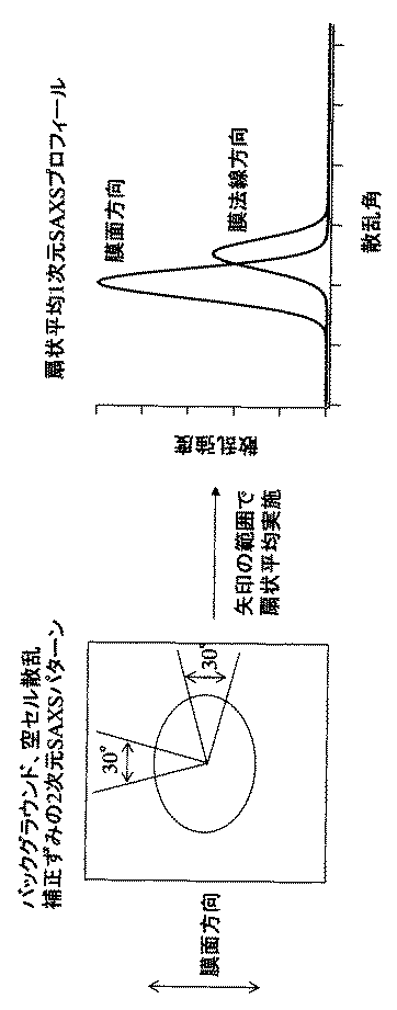
表1の結果、実施例1〜4ではいずれもQ値が1.5以上となっており、ミクロ相分離構造は膜表面に垂直に配向しているのに対し、比較例ではQ値が1.0以下であり、垂直配向していないことが分かる。 As a result of Table 1, in all of Examples 1 to 4, the Q value is 1.5 or more, and the microphase separation structure is oriented perpendicular to the film surface, whereas in the comparative example, the Q value is 1 It can be seen that the vertical alignment is not more than 0.0.
本発明によれば膜表面に対して垂直方向に配向したミクロ相分離構造を有したブロック共重合体膜を極めて簡便に製造することができる。本発明に従うと、広範な分野における高機能材料設計が可能となる。こうした高機能性材料として例えば、光記録媒体及び磁気記録媒体等のパターンドメディア、太陽電池、光スイッチ等の光電変換素子、光変調素子、光学位相差フイルム及び偏光フイルム等の高機能光学材料、レーザー発振素子等の発光素子、ディスプレー材料、有機FET素子、電解質膜、ナノ反応場膜、熱電変換素子、印刷用スクリーン、レジスト剤、精密フィルター、触媒、微細金型等が挙げられる。さらに、本発明中のブロック共重合体膜の少なくとも1成分を分解または溶解することによって得られるナノポーラス材料の用途として、触媒の担体、ナノスタンプ、ナノポーラス中空糸、吸着剤、精密フィルター等の分離膜、微細金型、ナノテンプレート等が挙げられる。 According to the present invention, a block copolymer membrane having a microphase-separated structure oriented in a direction perpendicular to the membrane surface can be produced very simply. According to the present invention, high-functional material design in a wide range of fields is possible. Examples of such highly functional materials include patterned media such as optical recording media and magnetic recording media, photoelectric conversion elements such as solar cells and optical switches, optical modulation elements, optical functional films such as optical phase difference films, and polarization films, Examples of the light emitting element such as a laser oscillation element, a display material, an organic FET element, an electrolyte film, a nanoreaction field film, a thermoelectric conversion element, a printing screen, a resist agent, a precision filter, a catalyst, and a fine mold. Furthermore, as a use of the nanoporous material obtained by decomposing or dissolving at least one component of the block copolymer membrane in the present invention, a separation membrane such as a catalyst carrier, nanostamp, nanoporous hollow fiber, adsorbent, precision filter, etc. , Fine molds, nanotemplates and the like.
Claims (7)
Priority Applications (1)
| Application Number | Priority Date | Filing Date | Title |
|---|---|---|---|
| JP2008243606A JP5283168B2 (en) | 2008-09-24 | 2008-09-24 | Method for producing polymer membrane having microphase separation structure |
Applications Claiming Priority (1)
| Application Number | Priority Date | Filing Date | Title |
|---|---|---|---|
| JP2008243606A JP5283168B2 (en) | 2008-09-24 | 2008-09-24 | Method for producing polymer membrane having microphase separation structure |
Publications (2)
| Publication Number | Publication Date |
|---|---|
| JP2010077172A true JP2010077172A (en) | 2010-04-08 |
| JP5283168B2 JP5283168B2 (en) | 2013-09-04 |
Family
ID=42207991
Family Applications (1)
| Application Number | Title | Priority Date | Filing Date |
|---|---|---|---|
| JP2008243606A Active JP5283168B2 (en) | 2008-09-24 | 2008-09-24 | Method for producing polymer membrane having microphase separation structure |
Country Status (1)
| Country | Link |
|---|---|
| JP (1) | JP5283168B2 (en) |
Cited By (3)
| Publication number | Priority date | Publication date | Assignee | Title |
|---|---|---|---|---|
| JP2014221868A (en) * | 2013-05-13 | 2014-11-27 | 国立大学法人名古屋大学 | Method for producing block copolymer and photonic material using the same |
| JP2017503042A (en) * | 2013-12-13 | 2017-01-26 | アルケマ フランス | A method that enables fabrication of nanometer structures by self-assembly of block copolymers |
| JP2021054960A (en) * | 2019-09-30 | 2021-04-08 | 株式会社ネオス | Water-slipping film and method for producing the same |
Citations (1)
| Publication number | Priority date | Publication date | Assignee | Title |
|---|---|---|---|---|
| JP2001151834A (en) * | 1999-06-07 | 2001-06-05 | Toshiba Corp | Pattern formation material, method for producing porous structure, method for forming pattern, electrochemical cell, hollow fiber filter, method for producing porous carbon structure, method for producing capacitor and method for producing catalytic layer of fuel cell |
-
2008
- 2008-09-24 JP JP2008243606A patent/JP5283168B2/en active Active
Patent Citations (1)
| Publication number | Priority date | Publication date | Assignee | Title |
|---|---|---|---|---|
| JP2001151834A (en) * | 1999-06-07 | 2001-06-05 | Toshiba Corp | Pattern formation material, method for producing porous structure, method for forming pattern, electrochemical cell, hollow fiber filter, method for producing porous carbon structure, method for producing capacitor and method for producing catalytic layer of fuel cell |
Cited By (4)
| Publication number | Priority date | Publication date | Assignee | Title |
|---|---|---|---|---|
| JP2014221868A (en) * | 2013-05-13 | 2014-11-27 | 国立大学法人名古屋大学 | Method for producing block copolymer and photonic material using the same |
| JP2017503042A (en) * | 2013-12-13 | 2017-01-26 | アルケマ フランス | A method that enables fabrication of nanometer structures by self-assembly of block copolymers |
| JP2021054960A (en) * | 2019-09-30 | 2021-04-08 | 株式会社ネオス | Water-slipping film and method for producing the same |
| JP7256727B2 (en) | 2019-09-30 | 2023-04-12 | 株式会社ネオス | Hydrophobic membrane and manufacturing method thereof |
Also Published As
| Publication number | Publication date |
|---|---|
| JP5283168B2 (en) | 2013-09-04 |
Similar Documents
| Publication | Publication Date | Title |
|---|---|---|
| Azuma et al. | Self-assembly of an ultrahigh-χ block copolymer with versatile etch selectivity | |
| Yang et al. | Directed self-assembly of polystyrene-b-poly (propylene carbonate) on chemical patterns via thermal annealing for next generation lithography | |
| Bang et al. | Effect of humidity on the ordering of PEO-based copolymer thin films | |
| TWI596119B (en) | Block copolymer | |
| Park et al. | Lateral ordering of cylindrical microdomains under solvent vapor | |
| TW201627334A (en) | Block copolymer | |
| KR20140090595A (en) | Block copolymers and lithographic patterning using same | |
| CN105722927B (en) | Method for controlling the period of nanostructured assemblies comprising blends of block copolymers | |
| Shi et al. | Designing nanostructured 3D printed materials by controlling macromolecular architecture | |
| Sperschneider et al. | Towards nanoporous membranes based on ABC triblock terpolymers | |
| Takekoh et al. | Multi‐length scale porous polymers | |
| TWI567127B (en) | Process for controlling the period of a nanostructured block copolymer film based on styrene and on methyl methacrylate, and nanostructured block copolymer film | |
| Lee et al. | A simple method for creating nanoporous block-copolymer thin films | |
| TW201202807A (en) | Process for production of liquid crystal element, and liquid crystal element | |
| Bennett et al. | Can ionic liquid additives be used to extend the scope of poly (styrene)-block-poly (methyl methacrylate) for directed self-assembly? | |
| JP5283168B2 (en) | Method for producing polymer membrane having microphase separation structure | |
| FR3014876A1 (en) | METHOD FOR PRODUCING A BLOCK COPOLYMER FILM ON A SUBSTRATE | |
| Qiang et al. | Polymer blend-filled nanoparticle films via monomer-driven infiltration of polymer and photopolymerization | |
| Mocan et al. | Self-assembly of PS-b-PNIPAM-b-PS block copolymer thin films via selective solvent annealing | |
| CN111615665A (en) | Method for producing a planar polymer stack | |
| Wang et al. | Solvent effect on the film formation and the stability of the surface properties of poly (methyl methacrylate) end-capped with fluorinated units | |
| Wang et al. | Synthesis of poly (methyl methacrylate)-b-polystyrene with high molecular weight by DPE seeded emulsion polymerization and its application in proton exchange membrane | |
| JP2005008701A (en) | Polymer film and method for producing the same | |
| TWI638838B (en) | Method for producing polymer film | |
| JP5283167B2 (en) | Polymer membrane with microphase separation structure |
Legal Events
| Date | Code | Title | Description |
|---|---|---|---|
| A621 | Written request for application examination |
Free format text: JAPANESE INTERMEDIATE CODE: A621 Effective date: 20110915 |
|
| A977 | Report on retrieval |
Free format text: JAPANESE INTERMEDIATE CODE: A971007 Effective date: 20121026 |
|
| A131 | Notification of reasons for refusal |
Free format text: JAPANESE INTERMEDIATE CODE: A131 Effective date: 20121113 |
|
| A521 | Written amendment |
Free format text: JAPANESE INTERMEDIATE CODE: A523 Effective date: 20130115 |
|
| RD03 | Notification of appointment of power of attorney |
Free format text: JAPANESE INTERMEDIATE CODE: A7423 Effective date: 20130115 |
|
| TRDD | Decision of grant or rejection written | ||
| A01 | Written decision to grant a patent or to grant a registration (utility model) |
Free format text: JAPANESE INTERMEDIATE CODE: A01 Effective date: 20130522 |
|
| A61 | First payment of annual fees (during grant procedure) |
Free format text: JAPANESE INTERMEDIATE CODE: A61 Effective date: 20130523 |
|
| R150 | Certificate of patent or registration of utility model |
Ref document number: 5283168 Country of ref document: JP Free format text: JAPANESE INTERMEDIATE CODE: R150 |
|
| S531 | Written request for registration of change of domicile |
Free format text: JAPANESE INTERMEDIATE CODE: R313531 |
|
| R350 | Written notification of registration of transfer |
Free format text: JAPANESE INTERMEDIATE CODE: R350 |
|
| S111 | Request for change of ownership or part of ownership |
Free format text: JAPANESE INTERMEDIATE CODE: R313115 |
|
| S111 | Request for change of ownership or part of ownership |
Free format text: JAPANESE INTERMEDIATE CODE: R313115 |
|
| R350 | Written notification of registration of transfer |
Free format text: JAPANESE INTERMEDIATE CODE: R350 |
|
| S531 | Written request for registration of change of domicile |
Free format text: JAPANESE INTERMEDIATE CODE: R313531 |
|
| R350 | Written notification of registration of transfer |
Free format text: JAPANESE INTERMEDIATE CODE: R350 |