JP2010076177A - Device for determining good/bad of injection molding machine - Google Patents
Device for determining good/bad of injection molding machine Download PDFInfo
- Publication number
- JP2010076177A JP2010076177A JP2008245466A JP2008245466A JP2010076177A JP 2010076177 A JP2010076177 A JP 2010076177A JP 2008245466 A JP2008245466 A JP 2008245466A JP 2008245466 A JP2008245466 A JP 2008245466A JP 2010076177 A JP2010076177 A JP 2010076177A
- Authority
- JP
- Japan
- Prior art keywords
- mode
- limit value
- determination
- lower limit
- upper limit
- Prior art date
- Legal status (The legal status is an assumption and is not a legal conclusion. Google has not performed a legal analysis and makes no representation as to the accuracy of the status listed.)
- Granted
Links
Images


Abstract
Description
本発明は、射出成形機の良否判別装置に関し、特に判別モードを設定可能な射出成形機の良否判別装置に関する。 The present invention relates to a quality determination device for an injection molding machine, and more particularly to a quality determination device for an injection molding machine in which a determination mode can be set.
生産の合理化のために成形品の良品,不良品の自動判別を行い、さらに不良品発生率を低下させ歩留まりを向上させることは、生産効率、経済性の観点から重要な課題である。 In order to streamline production, it is an important issue from the viewpoint of production efficiency and economy to automatically determine whether a molded product is non-defective or defective and further reduce the defective product generation rate to improve yield.
成形品質に影響を与える要因は多い。射出成形機において、成形サイクルにおける各ショット毎の製品の品質に影響を与える成形データ、例えば、型内圧、射出の初圧、射出速度、射出のピーク圧、計量時間、金型温度、射出保圧切替位置(V−P位置)、射出所要時間、型締力などの各物理量を測定し、測定により得られたこれらの値が各物理量に対して設定された許容範囲内にあるか否かにより製品の良否を判別することは公知の技術である。 There are many factors that affect the molding quality. In an injection molding machine, molding data that affects the product quality for each shot in the molding cycle, for example, mold pressure, initial pressure of injection, injection speed, peak pressure of injection, metering time, mold temperature, injection holding pressure Measure physical quantities such as switching position (VP position), required injection time, mold clamping force, etc., and check if these values are within the tolerances set for each physical quantity. It is a known technique to determine the quality of a product.
特許文献1には、通常の良否判別レンジに加えて第2の良否判別レンジを設け、前記第2の良否判別レンジを超えたときの成形品は不良品と判定されるとともに重度の異常とみなし、情報出力部から成形機の制御部へ異常であることを示す信号を出力し、成形機の運転を停止させる技術が開示されている。
In
特許文献2には、計測値が良否判別レンジ外である場合には警報を出力しオペレータに知らせたり、プロセス制御ユニットへ製品排出の停止あるいは次ショットの停止の出力を行う技術が開示されている。この文献には、前記警報の出力と前記製品排出の停止あるいは次ショットの停止の出力を良否判定の項目に応じて設定でき、また、1つの項目において警報出力と停止出力の両方を設定できる事項も開示されている。
射出成形の計測値である成形データとして型内圧を成形品質管理のための監視項目とした場合を例とする。型内圧が上限値を超えた時(型内圧が上がり過ぎた場合)はオーバーパックであり、金型に成形品が詰まる恐れがあるためアラーム判別としてアラーム出力と1サイクル停止を行う。他方、型内圧が下がり過ぎた時(下限値を下回った場合)にはショートショットであり、不良品ではあるが成形を続けることはできるため、不良品判別として不良品信号を出力するものの、生産効率、経済性の観点から、成形を継続したい場合がある。 As an example, a case where the in-mold pressure is used as a monitoring item for molding quality control as molding data which is a measurement value of injection molding will be described. When the mold internal pressure exceeds the upper limit (when the mold internal pressure rises too much), it is overpacked and the molded product may be clogged. Therefore, alarm output and one cycle stop are performed as alarm discrimination. On the other hand, when the mold internal pressure is too low (below the lower limit), it is a short shot and can continue to be molded even though it is a defective product. In some cases, it is desired to continue molding from the viewpoint of efficiency and economy.
しかし、背景技術で説明したように従来技術は、良否判別のレンジを用いる成形品の良否判断は、成形データが良否判別のレンジ内であるか否かに着目して行われるものであり、成形データが上限値を超えているのか、下限値を下回っているのかの区別がなされていない。従来技術における良否判別の方法を模式的に示すと図9のように表すことができる。図9から分るように、良否判別モードは前述したように良否判別レンジ内であるか否かを判別するモードでしかない。 However, as explained in the background art, in the prior art, the quality judgment of a molded product using the quality judgment range is performed by paying attention to whether the molding data is within the quality judgment range, and molding is performed. No distinction is made as to whether the data is above the upper limit or below the lower limit. FIG. 9 can schematically represent a quality determination method in the prior art. As can be seen from FIG. 9, the pass / fail judgment mode is only a mode for discriminating whether or not it is within the pass / fail judgment range as described above.
そのため、成形データが良否判別レンジの上限値を超えた場合においても下限値を下回った場合においても、図9に示されるように同じ判別モードが適用される。換言すれば、成形データが上限値を超えていた場合と下限値を超えて下回った場合とで異なった判別モードを選択することができない。したがって、前述した型内圧の場合には、上限値を超えた場合にはサイクル停止とし、下限値を下回った場合には不良品信号の出力といった異なった判別を行えない。 Therefore, even when the molding data exceeds the upper limit value of the pass / fail determination range and falls below the lower limit value, the same determination mode is applied as shown in FIG. In other words, it is not possible to select different discrimination modes when the molding data exceeds the upper limit and when the molding data exceeds the lower limit. Therefore, in the case of the mold internal pressure described above, the cycle stop is performed when the upper limit value is exceeded, and different determinations such as output of a defective product signal cannot be made when the lower limit value is exceeded.
そこで、本発明の目的は、良否判別の上限値を超えた場合と下限値を下回った場合において異なる判別モードを設定することができる射出成形機の良否判別装置を提供することである。 Accordingly, an object of the present invention is to provide a quality determination device for an injection molding machine capable of setting different determination modes when an upper limit value for quality determination is exceeded and when a lower limit value is exceeded.
本願の請求項1に係る発明は、射出成形機の成形品品質に影響を与える圧力、速度、時間等の物理量を各成形サイクル毎に測定する物理量測定手段と、良否判別の上限値および下限値を設定する良否判別レンジ設定手段と、前記物理量測定手段により測定した物理量と前記設定した良否判別の上限値とを比較し前記測定した物理量が前記上限値より大きい場合に上限値判別動作信号を出力する上限値判別動作手段と、前記物理量測定手段により測定した物理量と前記設定した良否判別の下限値とを比較し前記測定した物理量が前記下限値より小さい場合に下限値判別動作信号を出力する下限値判別動作手段と、前記上限値判別動作手段と前記下限値判別動作手段の判別動作をそれぞれ個別に設定する判別モード設定手段と、を備えたことを特徴とする射出成形機の良否判別装置である。
The invention according to
請求項2に係る発明は、前記判別モード設定手段は、少なくとも不良品信号の出力、射出成形機の運転停止信号の出力の2つのうちのいずれかの判別モードを設定できることを特徴とする請求項1に記載の射出成形機の良否判別装置である。
The invention according to
請求項3に係る発明は、前記判別モード設定手段は、あらかじめ判別モードの組み合わせをパターン化しておき設定できることを特徴とする請求項1または2のいずれか1つ記載の射出成形機の良否判別装置である。
The invention according to
本発明により、監視項目の成形データが良否判別レンジ外であった場合、それが上限値を超えた場合と下限値を下回った場合に応じて異なる判別モードを設定可能な射出成形機の良否判別装置を提供することができる。 According to the present invention, when the molding data of the monitoring item is out of the pass / fail judgment range, the pass / fail judgment of the injection molding machine that can set different discrimination modes depending on when it exceeds the upper limit value and below the lower limit value An apparatus can be provided.
以下、本発明の実施形態を図面と共に説明する。
図1は本発明の実施形態における判別モードの選択を説明する図である。本発明の実施形態では、計測した物理量が良否判別の上限値を超えた場合、(A)上限値良否判別モード、(B)上限値アラーム判別モード、(C)上限値サイクル停止判別モードの3つの判別モードの中から判別モードを選択可能であり、他方、計測した物理量が良否判別の下限値を下回った場合、(D)下限値良否判別モード、(E)下限値アラーム判別モード、(F)下限値サイクル停止判別モードの3つの判別モードの中から選択可能である。
Hereinafter, embodiments of the present invention will be described with reference to the drawings.
FIG. 1 is a diagram illustrating selection of a discrimination mode in the embodiment of the present invention. In the embodiment of the present invention, when the measured physical quantity exceeds the upper limit value for pass / fail judgment, (A) upper limit pass / fail judgment mode, (B) upper limit alarm judgment mode, and (C) upper limit cycle
ここで、上記(A)〜(F)の判別モードについて説明する。
●(A)上限値良否判別モード:この判別モードは、測定して得られた物理量が良否判別の上限値を超えた時、製品が不良であることを示す信号を出力するモードである。
●(B)上限値アラーム判別モード:この判別モードは、測定して得られた物理量が良否判別の上限値を超えた時、アラーム信号を出力するモードであり、射出成形機の停止を指令しないモードである。
●(C)上限値サイクル停止判別モード:この判別モードは、測定して得られた物理量が良否判別の上限値を超えた時、アラーム信号を出力すると共に射出成形機の停止信号を出力するモードである。
●(D)下限値良否判別モード:この判別モードは、測定して得られた物理量が良否判別の下限値を下回った時、製品が不良であることを示す信号を出力するモードである。
●(E)下限値アラーム判別モード:この判別モードは、測定して得られた物理量が良否判別の下限値を下回った時、アラーム信号を出力するモードであり、射出成形機の停止を指令しないモードである。
●(F)下限値サイクル停止判別モード:この判別モードは、測定して得られた物理量が良否判別の下限値を下回った時、アラーム信号を出力すると共に射出成形機の停止信号を出力するモードである。
Here, the discrimination modes (A) to (F) will be described.
(A) Upper limit value pass / fail discrimination mode: This discrimination mode is a mode for outputting a signal indicating that the product is defective when the physical quantity obtained by measurement exceeds the upper limit for pass / fail discrimination.
● (B) Upper limit alarm discrimination mode: This discrimination mode is a mode that outputs an alarm signal when the physical quantity obtained by measurement exceeds the upper limit for pass / fail judgment, and does not command the stop of the injection molding machine. Mode.
(C) Upper limit cycle stop discrimination mode: This discrimination mode is a mode that outputs an alarm signal and an injection molding machine stop signal when the measured physical quantity exceeds the upper limit for pass / fail judgment. It is.
(D) Lower limit value pass / fail judgment mode: This discrimination mode is a mode for outputting a signal indicating that the product is defective when the physical quantity obtained by measurement falls below the lower limit for pass / fail judgment.
● (E) Lower limit alarm judgment mode: This judgment mode is a mode that outputs an alarm signal when the measured physical quantity falls below the lower limit of pass / fail judgment, and does not command the injection molding machine to stop. Mode.
● (F) Lower limit cycle stop discrimination mode: This discrimination mode outputs an alarm signal and an injection molding machine stop signal when the measured physical quantity falls below the lower limit for pass / fail discrimination. It is.
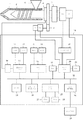
図2は本発明の実施形態の良否判別装置を備えた射出成形機の概略構成図である。符号1は射出成形機の射出シリンダ、符号2はスクリュである。スクリュ2は、駆動源の軸回転を射出軸方向の直線運動に変換するための駆動変換器5を介して射出用サーボモータM1により射出軸方向に駆動され、また、歯車機構3を介してスクリュ回転用サーボモータM2により計量回転されるようになっている。スクリュ2の基部には圧力検出器4が設けられ、スクリュ2の軸方向に作用する樹脂圧力、すなわち、射出保圧工程における射出保圧圧力や計量工程におけるスクリュ背圧が検出される。符号6はホッパであり樹脂材料を射出シリンダ1に供給する投入口である。
FIG. 2 is a schematic configuration diagram of an injection molding machine including the quality determination apparatus according to the embodiment of the present invention.
射出用サーボモータM1にはスクリュ2の位置や移動速度を検出するための位置・速度検出器P1が設けられ、また、スクリュ回転用サーボモータM2にはスクリュ2の回転位置や回転速度を検出するための位置・速度検出器P2が設けられている。
The injection servo motor M1 is provided with a position / speed detector P1 for detecting the position and movement speed of the
射出成形機の制御装置10は、数値制御用のマイクロプロセッサであるCNCCPU25、プログラマブルマシンコントローラ用のマイクロプロセッサであるPMCCPU18、サーボ制御用のマイクロプロセッサであるサーボCPU20および射出保圧圧力やスクリュ背圧のサンプリング処理を行う圧力モニタCPU17を有し、バス22を介して相互の入出力を選択することにより各マイクロプロセッサ間での情報伝達を行えるようになっている。
The
PMCCPU18には射出成形機のシーケンス動作を制御するシーケンスプログラムや製品の良否判別を行うための制御プログラム等を記憶したROM13および演算データの一時記憶等に用いられるRAM14が接続されている。ROM13には、更に本発明に関連する設定画面に関連した表示データ(図3、図4参照)等が格納されている。
Connected to the
CNCCPU25には、射出成形機を全体的に制御するプログラム等を記憶したROM28および演算データの一時記憶等に用いられるRAM27が接続されている。サーボCPU20には、サーボ制御専用の制御プログラムを格納したROM21やデータの一時記憶に用いられるRAM19が接続されている。
圧力モニタCPU17には、成形データのサンプリング処理等に関する制御プログラムを格納したROM11やデータの一時記憶に用いられるRAM12が接続されている。
Connected to the
The
また、サーボCPU20には、サーボCPU20からの指令に基づいて型締め用、エジェクタ用(図示省略)および射出用、スクリュ回転用等の各軸のサーボモータを駆動するサーボアンプ15が接続され、射出用サーボモータM1に配備した位置・速度検出器P1、スクリュ回転用サーボモータM2に配備した位置・速度検出器P2からの出力の各々がサーボCPU20に帰還され、RAM19に用意された現在位置記憶レジスタや現在速度記憶レジスタの各々に記憶されるようになっている。
The
成形データ保存用RAM24は不揮発性メモリであり、射出成形作業に関する成形条件(射出保圧条件、計量条件等)と各種設定値、パラメータ、マクロ変数等を従来と同様にして記憶する成形データ保存用のメモリである。インタフェース23は射出成形機の各部に配置したリミットスイッチや操作盤からの信号を受信したり、射出成形機の周辺機器等に各種の指令を伝達するための入出力インタフェースである。
The molding
CNCCPU25はROM28の制御プログラムに基づいて各軸のサーボCPU20へ移動指令を出力し、サーボCPU20は位置検出器,速度検出器からのフィードバック信号に基づいてサーボ制御を実行する。
The
表示装置付手動データ入力装置29はLCD表示回路26を介してバス22に接続され、各種設定画面の表示やデータの入力操作等、例えば、図3、図4に示される成形作業の監視項目に関連する設定画面を表示した状態での、成形データで監視する監視項目の選択操作や、良否判別の上限値,下限値の入力操作、判別モードの設定などの入力操作等が、各種ファンクションキーやテンキータッチパネル等によって行われるようになっている。
A manual
次に、図3および図4を用いて、図2に示した本発明の実施形態である射出成形機の良否判別装置の表示装置に表示される表示画面の例を説明する。
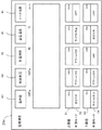
図3は表示画面の第1の例であり、上限値と下限値にそれぞれに判別モードを設定する例である。判別モードの設定、上限値、および下限値の入力は、前述した表示装置付手動データ入力装置29について説明した方法で行える。
Next, an example of a display screen displayed on the display device of the quality determination device for an injection molding machine according to the embodiment of the present invention shown in FIG. 2 will be described with reference to FIGS. 3 and 4.
FIG. 3 shows a first example of the display screen, in which a discrimination mode is set for each of the upper limit value and the lower limit value. The setting of the discrimination mode and the input of the upper limit value and the lower limit value can be performed by the method described for the manual data input device with
図3では、射出成形の監視項目として、型内圧、射出初圧、計量時間、金型温度、およびV−P位置をしたことを示している。例えば、型内圧50に対して上限値51、判別モード52、下限値53、判別モード54のように、それぞれの監視項目の物理量に対して、上限値、判別モード、下限値、および判別モード4つを設定する。判別モードの設定は上限値に対する判別モード52の設定と、下限値に対する判別モード54の設定の2つを行わなければならない。図3では、判別モード52には良否判別モードが設定されており、判別モード54にはサイクル停止モードが設定されている。
また、型内圧50以外の監視項目の物理量に対しても判別モードの設定をそれぞれ個別に行うことができ、それぞれ2回のモード設定作業が必要である。
FIG. 3 shows that the in-mold pressure, the initial injection pressure, the metering time, the mold temperature, and the VP position are set as the monitoring items for injection molding. For example, the upper limit value, the determination mode, the lower limit value, and the determination mode 4 for the physical quantities of the respective monitoring items, such as the
Also, the determination mode can be set individually for the physical quantities of the monitoring items other than the mold
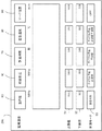
図4は表示画面の第2の例であり、1つの監視項目の物理量に対する上限値と下限値の判別モードの設定を1回の設定で行う例である。図4では判別モードの設定を上限値の判別モードと下限値の判別モードの設定を判別モード55の1回の設定作業で行う。図4に示した設定方法は、図3に示した設定方法に比較し判別モードの設定の手間が省け、また、設定ミスを減らすことができる。
FIG. 4 is a second example of the display screen, and is an example in which the determination mode of the upper limit value and the lower limit value for the physical quantity of one monitoring item is set by one setting. In FIG. 4, the discrimination mode is set in one setting operation of the
図4では、「良否判別モード」、「サイクル停止上限値」、「サイクル停止下限値」、「サイクル停止上限値下限値」が用意されている。
「良否判別モード」は、上限値判別モードを良否判別モード、下限値判別モードを良否判別モードとするパターン化した判別モードである。
「サイクル停止上限値モード」は、上限値判別モードをサイクル停止モード、下限値判別モードを良否判別モードとするパターン化した判別モードである。
「サイクル停止下限値モード」は、上限値判別モードを良否判別モード、下限値判別モードをサイクル停止モードとするパターン化した判別モードである。
「サイクル停止上限値下限値モード」は、上限値判別モードをサイクル停止モード、下限値判別モードをサイクル停止モードとするパターン化した判別モードである。
In FIG. 4, “good / bad determination mode”, “cycle stop upper limit value”, “cycle stop lower limit value”, and “cycle stop upper limit lower limit value” are prepared.
The “good / bad determination mode” is a patterned determination mode in which the upper limit determination mode is the pass / fail determination mode and the lower limit determination mode is the pass / fail determination mode.
The “cycle stop upper limit mode” is a patterned determination mode in which the upper limit determination mode is a cycle stop mode and the lower limit determination mode is a pass / fail determination mode.
The “cycle stop lower limit mode” is a patterned determination mode in which the upper limit determination mode is a pass / fail determination mode and the lower limit determination mode is a cycle stop mode.
The “cycle stop upper limit lower limit mode” is a patterned determination mode in which the upper limit determination mode is a cycle stop mode and the lower limit determination mode is a cycle stop mode.
次に、図5、図6、および図7を用いて、図2に示した本発明の実施形態における判別モードの設定と判別動作の処理のアルゴリズムを説明する。
まず、本発明における判別動作を設定する判別モードの設定について説明する。図5は、本発明における判別モードを設定するアルゴリズムを示すフローチャートである。この設定方法は、各物理量に対して上限値と下限値にそれぞれ判別モードを設定する方法である。図3に示される表示画面29aを参照しながら、図5のフローチャートを各ステップに従って説明する。
Next, with reference to FIG. 5, FIG. 6, and FIG. 7, the algorithm of the discrimination mode setting and discrimination operation processing in the embodiment of the present invention shown in FIG. 2 will be described.
First, the setting of the discrimination mode for setting the discrimination operation in the present invention will be described. FIG. 5 is a flowchart showing an algorithm for setting the discrimination mode in the present invention. This setting method is a method of setting the discrimination mode for the upper limit value and the lower limit value for each physical quantity. The flowchart of FIG. 5 will be described according to each step with reference to the
●[ステップSA1]設定する物理量を選択する。
●[ステップSA2]上限値判別モードの設定を読込む。より具体的には例えば、表示装置付手動データ入力装置29で入力された設定を読込む。例えば図3で監視項目の物理量である型内圧50を例にとると、上限値の判別モードは良否判別モードであり、下限値の判別モードも良否判別モードである。このように、一つの監視項目の物理用について上限値と下限値の2回の設定作業を行う必要がある。なお、入力作業は表示画面がタッチパネルであれば画面をタッチすることによりサイクリックに判別モードを表示し設定した判別モードを選択するようにできる。また、上限値や下限値の数値も判別モードの設定と合わせて入力作業を行ってもよいし、あらかじめ設定したデータを読込ませることによってもよい。
●[ステップSA3]ステップSA2で読込んだ判別モードの設定をメモリに記憶する。
●[ステップSA4],[ステップSA5]下限値判別モードの設定を読み込みメモリに記憶する。処理の内容はステップSA2、ステップSA3と同様である。
●[ステップSA6]監視項目の物理量に対して判別モードの設定が終了か否かを判断し、終了していなければ次の物理量に対して判別モードの設定処理を行うためステップSA1に戻り、設定が終了であれば判別モードの設定処理を終了する。
[Step SA1] A physical quantity to be set is selected.
[Step SA2] The setting of the upper limit value discrimination mode is read. More specifically, for example, the setting input by the manual
[Step SA3] The determination mode setting read in Step SA2 is stored in the memory.
[Step SA4], [Step SA5] The setting of the lower limit value discrimination mode is read and stored in the memory. The contents of the processing are the same as in steps SA2 and SA3.
[Step SA6] It is determined whether or not the discrimination mode has been set for the physical quantity of the monitored item. If not, the process returns to Step SA1 to perform the discrimination mode setting process for the next physical quantity and is set. If is finished, the determination mode setting process is terminated.
ステップSA2およびステップSA4で設定される判別モードは、図1に示されるように、(A)上限値良否判別モード、(B)上限値アラーム判別モード、(C)上限値サイクル停止判別モード、(D)下限値良否判別モード、(E)下限値アラーム判別モード、(F)下限値サイクル停止判別モード、および判別モードOFFから選択して入力されたモードである。
なお、図5のフローチャートでは上限値判別モードの設定を先に読込んで記憶しているが、下限値判別モードの設定を先に読込んで記憶してもよい。
As shown in FIG. 1, the determination modes set in step SA2 and step SA4 include (A) an upper limit value pass / fail determination mode, (B) an upper limit alarm determination mode, (C) an upper limit cycle stop determination mode, ( It is a mode selected and input from D) a lower limit value pass / fail judgment mode, (E) a lower limit alarm judgment mode, (F) a lower limit cycle stop judgment mode, and a judgment mode OFF.
In the flowchart of FIG. 5, the setting of the upper limit value determination mode is read and stored first, but the setting of the lower limit value determination mode may be read and stored first.
図6は、本発明における判別モードをパターン化して設定するアルゴリズムを示すフローチャートである。この設定形態は、判別モードの設定作業を効率的に行なうための設定手段である。図4に示される表示画面29bを参照しながら、図6のフローチャートを各ステップに従って説明する。
FIG. 6 is a flowchart showing an algorithm for patterning and setting the discrimination mode in the present invention. This setting form is setting means for efficiently performing the discrimination mode setting work. The flowchart of FIG. 6 will be described according to each step with reference to the
●[ステップSB1]設定する物理量を選択する。
●[ステップSB2]判別モードの設定を読込む。
●[ステップSB3]読込んだ判別モードに対応するパターン化した判別モードの設定を呼び出す。パターン化した判別モードは、あらかじめメモリに記憶させておく。図4や図6においては、パターン化した判別モードとして、「良否判別モード」、「サイクル停止上限値」、「サイクル停止下限値」、「サイクル停止上限値下限値」が用意されている。ぞれぞれの意味は前述したように、「良否判別モード」は、上限値判別モードを良否判別モード、下限値判別モードを良否判別モードとするパターン化した判別モードである。「サイクル停止上限値モード」は、上限値判別モードをサイクル停止モード、下限値判別モードを良否判別モードとするパターン化した判別モードである。「サイクル停止下限値モード」は、上限値判別モードを良否判別モード、下限値判別モードをサイクル停止モードとするパターン化した判別モードである。「サイクル停止上限値下限値モード」は、上限値判別モードをサイクル停止モード、下限値判別モードをサイクル停止モードとするパターン化した判別モードである。
[Step SB1] A physical quantity to be set is selected.
[Step SB2] Read the discrimination mode setting.
[Step SB3] Recall the setting of the patterned discrimination mode corresponding to the read discrimination mode. The patterned discrimination mode is stored in advance in a memory. In FIG. 4 and FIG. 6, “good / bad determination mode”, “cycle stop upper limit value”, “cycle stop lower limit value”, and “cycle stop upper limit lower limit value” are prepared as patterned determination modes. As described above, the meaning of each is the “good / bad determination mode”, which is a patterned determination mode in which the upper limit determination mode is the pass / fail determination mode and the lower limit determination mode is the pass / fail determination mode. The “cycle stop upper limit mode” is a patterned determination mode in which the upper limit determination mode is a cycle stop mode and the lower limit determination mode is a pass / fail determination mode. The “cycle stop lower limit mode” is a patterned determination mode in which the upper limit determination mode is a pass / fail determination mode and the lower limit determination mode is a cycle stop mode. The “cycle stop upper limit lower limit mode” is a patterned determination mode in which the upper limit determination mode is a cycle stop mode and the lower limit determination mode is a cycle stop mode.
次に、本発明における判別動作を説明する。図7は、本発明の実施形態で、3つの判別モードのアルゴリズムを示すフローチャートである。図8は、本発明の実施形態で、2つの判別モードのアルゴリズムを示すフローチャートである。
●[ステップSB4]ステップSB3で呼び出されたパターン化した判別モードが良否判別モードの場合には、ステップSB10へ移行し、上限値判別モードを良否判別モードとしてメモリに記憶し、下限値判別モードを良否判別モードとしてメモリに記憶し、ステップSB9へ移行する。良否判別モードでない場合には、ステップSB5へ移行する。
●[ステップSB5]ステップSB3で呼び出されたパターン化した判別モードがサイクル停止上限値モードの場合には、ステップSB11へ移行し、上限値判別モードをサイクル停止モードとしてメモリに記憶し、下限値判別モードを良否判別モードとしてメモリに記憶し、ステップSB9へ移行する。サイクル停止上限値モードでない場合には、ステップSB6へ移行する。
●[ステップSB6]ステップSB3で呼び出されたパターン化した判別モードがサイクル停止下限値モードの場合には、ステップSB12へ移行し、上限値判別モードを良否判別モードとしてメモリに記憶し、下限値判別モードをサイクル停止モードとしてメモリに記憶し、ステップSB9へ移行する。サイクル停止下限値モードでない場合には、ステップSB7へ移行する。
●[ステップSB7]ステップSB3で呼び出されたパターン化した判別モードがサイクル停止上限値下限値モードの場合には、ステップSB13へ移行し、上限値判別モードをサイクル停止モードとしてメモリに記憶し、下限値判別モードをサイクル停止モードとしてメモリに記憶し、ステップSB9へ移行する。サイクル停止上限値下限値モードでない場合には、ステップSB8へ移行する。
●[ステップSB8]ステップSB2で読み込まれた判別モードがOFF(オフ)の場合には、ステップSB14へ移行し、判別モードをOFF(オフ)としてメモリに記憶する。
●[ステップSB9]監視項目の物理量に対して判別モードの設定が終了か否かを判断し、終了していなければ次の物理量に対して判別モードの設定処理を行うためステップSB1に戻り、設定が終了であれば判別モードの設定処理を終了する。
Next, the discrimination operation in the present invention will be described. FIG. 7 is a flowchart showing an algorithm of three discrimination modes in the embodiment of the present invention. FIG. 8 is a flowchart showing an algorithm of two discrimination modes in the embodiment of the present invention.
[Step SB4] When the patterned discrimination mode called in step SB3 is the pass / fail discrimination mode, the process proceeds to step SB10, the upper limit discriminating mode is stored in the memory as the pass / fail discrimination mode, and the lower limit discriminating mode is set. The pass / fail judgment mode is stored in the memory, and the process proceeds to step SB9. If it is not the pass / fail judgment mode, the process proceeds to step SB5.
[Step SB5] If the patterned discrimination mode called in Step SB3 is the cycle stop upper limit value mode, the process proceeds to Step SB11, the upper limit discriminating mode is stored in the memory as the cycle stop mode, and the lower limit value discrimination is performed. The mode is stored in the memory as a pass / fail judgment mode, and the process proceeds to step SB9. If it is not the cycle stop upper limit value mode, the process proceeds to step SB6.
[Step SB6] If the patterned discrimination mode called in Step SB3 is the cycle stop lower limit mode, the process proceeds to Step SB12, the upper limit discriminating mode is stored in the memory as the pass / fail discrimination mode, and the lower limit discriminating is performed. The mode is stored in the memory as the cycle stop mode, and the process proceeds to step SB9. If it is not in the cycle stop lower limit mode, the process proceeds to step SB7.
[Step SB7] If the patterned determination mode called in Step SB3 is the cycle stop upper limit lower limit value mode, the process proceeds to Step SB13, where the upper limit determination mode is stored in the memory as the cycle stop mode, and the lower limit is set. The value determination mode is stored in the memory as the cycle stop mode, and the process proceeds to step SB9. If it is not in the cycle stop upper limit lower limit mode, the process proceeds to step SB8.
[Step SB8] If the determination mode read in step SB2 is OFF (off), the process proceeds to step SB14, and the determination mode is stored in the memory as OFF (off).
[Step SB9] It is determined whether or not the discrimination mode setting is completed for the physical quantity of the monitoring item. If is finished, the determination mode setting process is terminated.
なお、図6に示されるフローチャートでは、良否判別モードか、サイクル停止上限値か、サイクル停止下限値か、サイクル停止上限値下限値か、判別モードOFFかの順番に判断しているが、この順番に意味はないので順番を入れ替えたフローチャートとしてもよい。 In the flowchart shown in FIG. 6, the determination is made in the order of the pass / fail determination mode, the cycle stop upper limit value, the cycle stop lower limit value, the cycle stop upper limit lower limit value, or the determination mode OFF. Since there is no meaning, it may be a flowchart in which the order is changed.
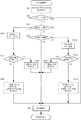
次に、図7を用いて本発明の実施形態における判別処理のアルゴリズムを説明する。図7に示される実施形態では、上限値良否判別モード,下限値良否判別モード、上限値アラーム判別モード,下限値アラーム判別モード、上限値サイクル停止モード,下限値サイクル停止モードの判別動作の出力をなす。以下、各ステップにしたがって説明する。なお、判別処理に実行タイミングは従来の良否判別装置と同様であり、少なくとも、1成形サイクルの型開き動作終了時点で判別処理が終了するように設定する。 Next, the discrimination processing algorithm in the embodiment of the present invention will be described with reference to FIG. In the embodiment shown in FIG. 7, the output of the discrimination operation of the upper limit value pass / fail judgment mode, the lower limit value pass / fail judgment mode, the upper limit alarm judgment mode, the lower limit alarm judgment mode, the upper limit cycle stop mode, and the lower limit cycle stop mode is output. Eggplant. Hereinafter, it demonstrates according to each step. Note that the execution timing of the determination process is the same as that of the conventional quality determination apparatus, and is set so that the determination process is completed at least when the mold opening operation of one molding cycle ends.
●[ステップSC1]物理量である測定値を取得する。物理量の測定値は1成形サイクルの中で所定サンプリング周期毎に得られる。もしくは、例えば、図2に示されるRAM12、RAM14などの射出成形機の制御装置のメモリに格納されている。
●[ステップSC2]判別モードがOFF(オフ)か否か判断し、判別モードがOFFの場合にはステップSC5へ移行する。判別モードがOFFでない場合には、ステップSC3へ移行する。
●[ステップSC3]測定値が上限値を超えているか否かを判断し、超えていればステップSC6へ移行し、超えていなければステップSC4へ移行する。
●[ステップSC4]測定値が下限値を下回っているか否かを判断し、下回っていればステップSC12へ移行し、下回っていなければステップSC5へ移行する。
●[ステップSC5]ステップSC1で取得した物理量である測定値を表示する。
[Step SC1] A measurement value that is a physical quantity is acquired. The measured value of the physical quantity is obtained every predetermined sampling period in one molding cycle. Alternatively, for example, it is stored in a memory of a control device of an injection molding machine such as the
[Step SC2] It is determined whether or not the determination mode is OFF. If the determination mode is OFF, the process proceeds to step SC5. If the determination mode is not OFF, the process proceeds to step SC3.
[Step SC3] It is determined whether or not the measured value exceeds the upper limit value. If it exceeds, the process proceeds to Step SC6, and if not, the process proceeds to Step SC4.
[Step SC4] It is determined whether or not the measured value is below the lower limit value. If it is below, the process proceeds to Step SC12, and if not, the process proceeds to Step SC5.
[Step SC5] The measured value, which is the physical quantity acquired in Step SC1, is displayed.
●[ステップSC6]ステップSC3から移行したので、設定して記憶されている上限値判別モードをメモリから読み込み、ステップSC7へ移行する。なお、メモリから読み込まれる判別モードの設定は図5や図6に示される処理によりあらかじめ記憶されている。
●[ステップSC7]ステップSC6で読み込んだ判別モードが上限値良否判別モードである場合には、ステップSC8へ移行する。上限値良否判別モードでない場合にはステップSC9へ移行する。
●[ステップSC8]上限値不良品信号を出力し、ステップSC5へ移行する。
●[ステップSC9]ステップSC6で読み込んだ判別モードが上限値アラーム判別モードである場合には、ステップSC10へ移行する。上限値アラーム判別モードでない場合にはステップSC11へ移行する。
[Step SC6] Since the process has shifted from step SC3, the upper limit value determination mode that has been set and stored is read from the memory, and the process proceeds to step SC7. Note that the setting of the discrimination mode read from the memory is stored in advance by the processing shown in FIGS.
[Step SC7] If the determination mode read in step SC6 is the upper limit value pass / fail determination mode, the process proceeds to step SC8. When it is not the upper limit value pass / fail judgment mode, the routine proceeds to step SC9.
[Step SC8] An upper limit value defective product signal is output, and the process proceeds to Step SC5.
[Step SC9] If the determination mode read in step SC6 is the upper limit alarm determination mode, the process proceeds to step SC10. If it is not the upper limit alarm determination mode, the process proceeds to step SC11.
●[ステップSC10]上限値アラーム信号を出力し、ステップSC5へ移行する。
●[ステップSC11]上限値サイクル停止モードであるので、上限値アラーム信号を出力し、かつ、上限値サイクル停止信号を出力し、ステップSC5へ移行する。
●[ステップSC12]ステップSC4から移行したので、設定して記憶されている下限値判別モードをメモリから読み込み、ステップSC13へ移行する。なお、メモリから読み込まれる判別モードの設定は図5や図6に示される処理によりあらかじめ記憶されている。
[Step SC10] An upper limit alarm signal is output, and the process proceeds to Step SC5.
[Step SC11] Since it is the upper limit cycle stop mode, an upper limit alarm signal is output and an upper limit cycle stop signal is output, and the process proceeds to Step SC5.
[Step SC12] Since the process has proceeded from Step SC4, the lower limit value determination mode set and stored is read from the memory, and the process proceeds to Step SC13. Note that the setting of the discrimination mode read from the memory is stored in advance by the processing shown in FIGS.
●[ステップSC13]ステップSC12で読み込んだ判別モードが下限値良否判別モードである場合には、ステップSC14へ移行する。下限値良否判別モードでない場合にはステップSC15へ移行する。
●[ステップSC14]下限値不良品信号を出力しステップSC5へ移行する。
●[ステップSC15]ステップSC12で読み込んだ判別モードが下限値アラーム判別モードである場合には、ステップSC16へ移行する。下限値アラーム判別モードでない場合にはステップSC17へ移行する。
●[ステップSC16]下限値アラーム信号を出力し、ステップSC5へ移行する。
●[ステップSC17]下限値サイクル停止モードであるので、下限値アラーム信号を出力し、かつ、下限値サイクル停止信号を出力し、ステップSC5へ移行する。
[Step SC13] If the determination mode read in step SC12 is the lower limit value pass / fail determination mode, the process proceeds to step SC14. If it is not the lower limit value pass / fail discrimination mode, the routine proceeds to step SC15.
[Step SC14] A lower limit value defective product signal is output and the process proceeds to Step SC5.
[Step SC15] If the determination mode read in step SC12 is the lower limit alarm determination mode, the process proceeds to step SC16. If it is not the lower limit alarm determination mode, the process proceeds to step SC17.
[Step SC16] A lower limit alarm signal is output, and the process proceeds to Step SC5.
[Step SC17] Since it is the lower limit cycle stop mode, the lower limit alarm signal is output and the lower limit cycle stop signal is output, and the process proceeds to Step SC5.
なお、図7のステップSC10では上限値アラーム信号出力、ステップSC16では下限値アラーム信号出力とされているが、ステップSC3あるいはステップSC4での判断結果に基づいて、ステップSC10で上限値不良品信号、ステップSC16で下限値不良品信号を併せて出力するようにしてもよい。同様に、ステップSC11においても上限値不良品信号、ステップSC17で下限値不良品信号を出力するようにしてもよい。 In step SC10 of FIG. 7, the upper limit alarm signal is output, and in step SC16, the lower limit alarm signal is output. However, based on the determination result in step SC3 or step SC4, the upper limit value defective product signal in step SC10, In step SC16, a lower limit value defective product signal may be output together. Similarly, an upper limit value defective product signal may be output in step SC11, and a lower limit value defective product signal may be output in step SC17.
図8に示される実施形態では、上限値良否判別モード,下限値良否判別モード、上限値サイクル停止モード,下限値サイクル停止モードの判別処理を行う。以下、各ステップにしたがって説明する。
●[ステップSD1]物理量である測定値を取得する。物理量の測定値は1成形サイクルの中で所定サンプリング周期毎に得られる。もしくは、例えば、図2に示されるRAM12、RAM14などの射出成形機の制御装置のメモリに格納されている。
●[ステップSD2]判別モードがOFF(オフ)か否か判断し、判別モードがOFFの場合にはステップSD5へ移行する。判別モードがOFFでない場合には、ステップSD3へ移行する。
In the embodiment shown in FIG. 8, the upper limit value pass / fail discrimination mode, the lower limit pass / fail discrimination mode, the upper limit cycle stop mode, and the lower limit cycle stop mode are determined. Hereinafter, it demonstrates according to each step.
[Step SD1] A measurement value that is a physical quantity is acquired. The measured value of the physical quantity is obtained every predetermined sampling period in one molding cycle. Alternatively, for example, it is stored in a memory of a control device of an injection molding machine such as the
[Step SD2] It is determined whether or not the determination mode is OFF. If the determination mode is OFF, the process proceeds to step SD5. If the determination mode is not OFF, the process proceeds to step SD3.
●[ステップSD3]測定値が上限値を超えているか否かを判断し、超えていればステップSD6へ移行し、超えていなければステップSD4へ移行する。
●[ステップSD4]測定値が下限値を下回っているか否かを判断し、下回っていればステップSD10へ移行し、下回っていなければステップSD5へ移行する。
●[ステップSD5]ステップSD1で取得した物理量である測定値を表示する。
[Step SD3] It is determined whether or not the measured value exceeds the upper limit value. If it exceeds, the process proceeds to Step SD6, and if not, the process proceeds to Step SD4.
[Step SD4] It is determined whether or not the measured value is below the lower limit value. If the measured value is below the lower limit value, the process proceeds to Step SD10, and if not, the process proceeds to Step SD5.
[Step SD5] The measured value, which is the physical quantity acquired in Step SD1, is displayed.
●[ステップSD6]ステップSD3から移行したので、設定して記憶されている上限値判別モードをメモリから読み込み、ステップSD7へ移行する。なお、メモリから読み込まれる判別モードの設定は図5や図6に示される処理によりあらかじめ記憶されている。
●[ステップSD7]ステップSD6で読み込んだ判別モードが上限値良否判別モードである場合には、ステップSD8へ移行する。上限値良否判別モードでない場合にはステップSD9へ移行する。
●[ステップSD8]上限値不良品信号を出力し、ステップSD5へ移行する。
[Step SD6] Since the process has shifted from Step SD3, the upper limit value determination mode set and stored is read from the memory, and the process proceeds to Step SD7. Note that the setting of the discrimination mode read from the memory is stored in advance by the processing shown in FIGS.
[Step SD7] When the determination mode read in step SD6 is the upper limit value pass / fail determination mode, the process proceeds to step SD8. When it is not the upper limit value pass / fail judgment mode, the process proceeds to step SD9.
[Step SD8] An upper limit value defective product signal is output, and the process proceeds to Step SD5.
●[ステップSD9]上限値サイクル停止モードであるので、上限値アラーム信号を出力し、かつ、上限値サイクル停止信号を出力し、ステップSD5へ移行する。
●[ステップSD10]ステップSD4から移行したので、設定して記憶されている下限値判別モードをメモリから読み込み、ステップSD11へ移行する。なお、メモリから読み込まれる判別モードの設定は図5や図6に示される処理によりあらかじめ記憶されている。
[Step SD9] Since it is the upper limit cycle stop mode, an upper limit alarm signal is output and an upper limit cycle stop signal is output, and the process proceeds to step SD5.
[Step SD10] Since the process has shifted from step SD4, the lower limit value determination mode that has been set and stored is read from the memory, and the process proceeds to step SD11. Note that the setting of the discrimination mode read from the memory is stored in advance by the processing shown in FIGS.
●[ステップSD11]ステップSD10で読み込んだ判別モードが下限値良否判別モードである場合には、ステップSD12へ移行する。下限値良否判別モードでない場合にはステップSD13へ移行する。
●[ステップSD12]下限値不良品信号を出力しステップSD5へ移行する。
●[ステップSD13]下限値サイクル停止モードであるので、下限アラーム信号を出力し、かつ、下限値サイクル停止信号を出力し、ステップSD5へ移行する。
[Step SD11] If the determination mode read in step SD10 is the lower limit value pass / fail determination mode, the process proceeds to step SD12. If it is not the lower limit value pass / fail discrimination mode, the process proceeds to step SD13.
[Step SD12] A lower limit value defective product signal is output and the process proceeds to Step SD5.
[Step SD13] Since it is the lower limit cycle stop mode, a lower limit alarm signal is output and a lower limit cycle stop signal is output, and the process proceeds to Step SD5.
なお、ステップSD3での判断結果に基づいてステップSD9で上限値不良品信号、ステップSD4での判断結果に基づいてステップSD13で下限値不良品信号を併せて出力するようにしてもよい。 The upper limit value defective product signal may be output in step SD9 based on the determination result in step SD3, and the lower limit value defective product signal may be output in step SD13 based on the determination result in step SD4.
A 上限値良否判別モード
B 上限値アラーム判別モード
C 上限値サイクル停止判別モード
D 下限値良否判別モード
E 下限値アラーム判別モード
F 下限値サイクル停止判別モード
A Upper limit value pass / fail judgment mode B Upper limit alarm discrimination mode C Upper limit cycle stop judgment mode D Lower limit pass / fail judgment mode E Lower limit alarm judgment mode F Lower limit cycle stop judgment mode
Claims (3)
良否判別の上限値および下限値を設定する良否判別レンジ設定手段と、
前記物理量測定手段により測定した物理量と前記設定した良否判別の上限値とを比較し前記測定した物理量が前記上限値より大きい場合に上限値判別動作信号を出力する上限値判別動作手段と、
前記物理量測定手段により測定した物理量と前記設定した良否判別の下限値とを比較し前記測定した物理量が前記下限値より小さい場合に下限値判別動作信号を出力する下限値判別動作手段と、
前記上限値判別動作手段と前記下限値判別動作手段の判別動作をそれぞれ個別に設定する判別モード設定手段と、
を備えたことを特徴とする射出成形機の良否判別装置。 Physical quantity measuring means for measuring physical quantities such as pressure, speed, time, etc. that affect the quality of the molded product of the injection molding machine for each molding cycle;
Pass / fail judgment range setting means for setting upper and lower limits for pass / fail judgment;
An upper limit value determining operation means for comparing the physical quantity measured by the physical quantity measuring means with the set upper limit value of the pass / fail determination and outputting an upper limit value determining operation signal when the measured physical quantity is larger than the upper limit value;
A lower limit value determining operation means for comparing the physical quantity measured by the physical quantity measuring means and the set lower limit value of the pass / fail determination and outputting a lower limit value determining operation signal when the measured physical quantity is smaller than the lower limit value;
A determination mode setting means for individually setting the determination operations of the upper limit value determination operation means and the lower limit value determination operation means;
A quality determination device for an injection molding machine, comprising:
Priority Applications (1)
| Application Number | Priority Date | Filing Date | Title |
|---|---|---|---|
| JP2008245466A JP5301935B2 (en) | 2008-09-25 | 2008-09-25 | Injection molding machine pass / fail judgment device |
Applications Claiming Priority (1)
| Application Number | Priority Date | Filing Date | Title |
|---|---|---|---|
| JP2008245466A JP5301935B2 (en) | 2008-09-25 | 2008-09-25 | Injection molding machine pass / fail judgment device |
Publications (2)
| Publication Number | Publication Date |
|---|---|
| JP2010076177A true JP2010076177A (en) | 2010-04-08 |
| JP5301935B2 JP5301935B2 (en) | 2013-09-25 |
Family
ID=42207198
Family Applications (1)
| Application Number | Title | Priority Date | Filing Date |
|---|---|---|---|
| JP2008245466A Active JP5301935B2 (en) | 2008-09-25 | 2008-09-25 | Injection molding machine pass / fail judgment device |
Country Status (1)
| Country | Link |
|---|---|
| JP (1) | JP5301935B2 (en) |
Cited By (3)
| Publication number | Priority date | Publication date | Assignee | Title |
|---|---|---|---|---|
| JP2013533558A (en) * | 2010-07-21 | 2013-08-22 | キストラー ホールディング アクチエンゲゼルシャフト | Apparatus and method for controlling the course of a part manufacturing process |
| DE102017002607A1 (en) | 2016-03-24 | 2017-09-28 | Fanuc Corporation | Machining system that determines the acceptance / rejection of workpieces |
| WO2023223421A1 (en) * | 2022-05-17 | 2023-11-23 | ファナック株式会社 | Device for controlling injection molding machine |
Families Citing this family (1)
| Publication number | Priority date | Publication date | Assignee | Title |
|---|---|---|---|---|
| US20180016446A1 (en) * | 2015-01-27 | 2018-01-18 | Nissan Chemical Industries, Ltd. | Resin thin-film-forming composition for easily-peelable protection |
Citations (8)
| Publication number | Priority date | Publication date | Assignee | Title |
|---|---|---|---|---|
| JPS57212041A (en) * | 1981-06-24 | 1982-12-27 | Toshiba Mach Co Ltd | Molding data collector for injection molding machine |
| JPS6024915A (en) * | 1983-07-20 | 1985-02-07 | Nissei Plastics Ind Co | Monitoring method of molding machine |
| JPH04135727A (en) * | 1990-09-27 | 1992-05-11 | Fanuc Ltd | Method of judging quality of molding |
| JPH07108579A (en) * | 1993-10-12 | 1995-04-25 | Fanuc Ltd | Discriminating method for product quality of injection molding machine |
| JPH0985792A (en) * | 1995-09-27 | 1997-03-31 | Fanuc Ltd | Method of clamping control in injection molding machine |
| JPH09109219A (en) * | 1995-10-20 | 1997-04-28 | Fanuc Ltd | Product propriety discriminating method for injection molding machine |
| JPH09267163A (en) * | 1996-03-29 | 1997-10-14 | Toshiba Mach Co Ltd | Method for deciding normal or defective quality of product in die casting machine |
| JP2003080526A (en) * | 2001-09-10 | 2003-03-19 | Star Seiki Co Ltd | Method for diagnosing abnormality of ejector assembly |
-
2008
- 2008-09-25 JP JP2008245466A patent/JP5301935B2/en active Active
Patent Citations (8)
| Publication number | Priority date | Publication date | Assignee | Title |
|---|---|---|---|---|
| JPS57212041A (en) * | 1981-06-24 | 1982-12-27 | Toshiba Mach Co Ltd | Molding data collector for injection molding machine |
| JPS6024915A (en) * | 1983-07-20 | 1985-02-07 | Nissei Plastics Ind Co | Monitoring method of molding machine |
| JPH04135727A (en) * | 1990-09-27 | 1992-05-11 | Fanuc Ltd | Method of judging quality of molding |
| JPH07108579A (en) * | 1993-10-12 | 1995-04-25 | Fanuc Ltd | Discriminating method for product quality of injection molding machine |
| JPH0985792A (en) * | 1995-09-27 | 1997-03-31 | Fanuc Ltd | Method of clamping control in injection molding machine |
| JPH09109219A (en) * | 1995-10-20 | 1997-04-28 | Fanuc Ltd | Product propriety discriminating method for injection molding machine |
| JPH09267163A (en) * | 1996-03-29 | 1997-10-14 | Toshiba Mach Co Ltd | Method for deciding normal or defective quality of product in die casting machine |
| JP2003080526A (en) * | 2001-09-10 | 2003-03-19 | Star Seiki Co Ltd | Method for diagnosing abnormality of ejector assembly |
Cited By (8)
| Publication number | Priority date | Publication date | Assignee | Title |
|---|---|---|---|---|
| JP2013533558A (en) * | 2010-07-21 | 2013-08-22 | キストラー ホールディング アクチエンゲゼルシャフト | Apparatus and method for controlling the course of a part manufacturing process |
| JP2016197432A (en) * | 2010-07-21 | 2016-11-24 | キストラー ホールディング アクチエンゲゼルシャフト | Device and method for controlling process of manufacturing step of component |
| DE102017002607A1 (en) | 2016-03-24 | 2017-09-28 | Fanuc Corporation | Machining system that determines the acceptance / rejection of workpieces |
| CN107229252A (en) * | 2016-03-24 | 2017-10-03 | 发那科株式会社 | Judge the whether qualified processing equipment system of workpiece |
| US10254750B2 (en) | 2016-03-24 | 2019-04-09 | Fanuc Corporation | Machining machine system which determines acceptance/rejection of workpieces |
| CN107229252B (en) * | 2016-03-24 | 2019-05-03 | 发那科株式会社 | Determine the qualified or not processing equipment system of workpiece |
| DE102017002607B4 (en) | 2016-03-24 | 2020-06-04 | Fanuc Corporation | Processing machine system that determines the acceptance / rejection of workpieces |
| WO2023223421A1 (en) * | 2022-05-17 | 2023-11-23 | ファナック株式会社 | Device for controlling injection molding machine |
Also Published As
| Publication number | Publication date |
|---|---|
| JP5301935B2 (en) | 2013-09-25 |
Similar Documents
| Publication | Publication Date | Title |
|---|---|---|
| US6616872B2 (en) | Method of and apparatus for determining separating force of molded product from mold | |
| JP5301935B2 (en) | Injection molding machine pass / fail judgment device | |
| JP4168036B2 (en) | Pressure abnormality detection device for injection molding machine | |
| US11150636B2 (en) | State determination device and state determination method | |
| WO2013008274A1 (en) | Numerical control apparatus | |
| JP2009279891A (en) | Abnormality detection apparatus of injection molding machine | |
| JP5394093B2 (en) | Numerical control device for controlling a machine tool having a tool breakage detection function | |
| JP5289528B2 (en) | Nozzle touch control device for injection molding machine | |
| JP2008055698A (en) | Injection molding machine equipped with operation data indicating device | |
| JP2007196604A (en) | Data display method of molding machine and data display device therefor | |
| JP4297280B2 (en) | Waveform display method and apparatus for injection molding | |
| JP4571044B2 (en) | Monitoring display device and display method | |
| JP4263661B2 (en) | Monitoring display method of molding machine | |
| JP2003200456A (en) | Injection molding machine and display thereof | |
| JP4782469B2 (en) | Sewing control device for sewing machine | |
| JP2014213455A (en) | Display device of injection molder | |
| JP2007196480A (en) | Data processing method of molding machine and data processor therefor | |
| JP2009000373A (en) | Production management device of sewing machine | |
| JP4081242B2 (en) | Monitoring display device and display method | |
| JP3484629B2 (en) | Self-diagnosis device of injection molding machine | |
| JP2006167069A (en) | Sewing recorder for sewing machine | |
| JP2009012380A (en) | Method of displaying data of molding machine | |
| JP2021066057A (en) | Injection molding machine management device and injection molding machine | |
| WO2024057461A1 (en) | Determination device and determination method | |
| JP5073562B2 (en) | Pressure abnormality detection device for injection molding machine |
Legal Events
| Date | Code | Title | Description |
|---|---|---|---|
| A621 | Written request for application examination |
Free format text: JAPANESE INTERMEDIATE CODE: A621 Effective date: 20110523 |
|
| A977 | Report on retrieval |
Free format text: JAPANESE INTERMEDIATE CODE: A971007 Effective date: 20121220 |
|
| A131 | Notification of reasons for refusal |
Free format text: JAPANESE INTERMEDIATE CODE: A131 Effective date: 20130108 |
|
| A521 | Written amendment |
Free format text: JAPANESE INTERMEDIATE CODE: A523 Effective date: 20130220 |
|
| A131 | Notification of reasons for refusal |
Free format text: JAPANESE INTERMEDIATE CODE: A131 Effective date: 20130319 |
|
| A521 | Written amendment |
Free format text: JAPANESE INTERMEDIATE CODE: A523 Effective date: 20130509 |
|
| TRDD | Decision of grant or rejection written | ||
| A01 | Written decision to grant a patent or to grant a registration (utility model) |
Free format text: JAPANESE INTERMEDIATE CODE: A01 Effective date: 20130528 |
|
| A61 | First payment of annual fees (during grant procedure) |
Free format text: JAPANESE INTERMEDIATE CODE: A61 Effective date: 20130620 |
|
| R150 | Certificate of patent or registration of utility model |
Ref document number: 5301935 Country of ref document: JP Free format text: JAPANESE INTERMEDIATE CODE: R150 Free format text: JAPANESE INTERMEDIATE CODE: R150 |