JP2010074962A - Tilt type cable duct - Google Patents
Tilt type cable duct Download PDFInfo
- Publication number
- JP2010074962A JP2010074962A JP2008240073A JP2008240073A JP2010074962A JP 2010074962 A JP2010074962 A JP 2010074962A JP 2008240073 A JP2008240073 A JP 2008240073A JP 2008240073 A JP2008240073 A JP 2008240073A JP 2010074962 A JP2010074962 A JP 2010074962A
- Authority
- JP
- Japan
- Prior art keywords
- plate
- cable
- duct
- front plate
- end portion
- Prior art date
- Legal status (The legal status is an assumption and is not a legal conclusion. Google has not performed a legal analysis and makes no representation as to the accuracy of the status listed.)
- Granted
Links
- XEEYBQQBJWHFJM-UHFFFAOYSA-N Iron Chemical compound [Fe] XEEYBQQBJWHFJM-UHFFFAOYSA-N 0.000 claims description 4
- 229910052751 metal Inorganic materials 0.000 claims description 4
- 239000002184 metal Substances 0.000 claims description 4
- 230000000694 effects Effects 0.000 claims description 3
- 239000000956 alloy Substances 0.000 claims description 2
- 229910045601 alloy Inorganic materials 0.000 claims description 2
- 229910052782 aluminium Inorganic materials 0.000 claims description 2
- XAGFODPZIPBFFR-UHFFFAOYSA-N aluminium Chemical compound [Al] XAGFODPZIPBFFR-UHFFFAOYSA-N 0.000 claims description 2
- 229910052742 iron Inorganic materials 0.000 claims description 2
- 229910000831 Steel Inorganic materials 0.000 description 3
- 230000008859 change Effects 0.000 description 3
- 239000010959 steel Substances 0.000 description 3
- 238000007689 inspection Methods 0.000 description 2
- 238000009434 installation Methods 0.000 description 2
- 238000012423 maintenance Methods 0.000 description 2
- 238000004519 manufacturing process Methods 0.000 description 2
- 239000000463 material Substances 0.000 description 2
- 230000009467 reduction Effects 0.000 description 2
- 239000002699 waste material Substances 0.000 description 2
- 238000004891 communication Methods 0.000 description 1
- 230000008878 coupling Effects 0.000 description 1
- 238000010168 coupling process Methods 0.000 description 1
- 238000005859 coupling reaction Methods 0.000 description 1
- 239000002905 metal composite material Substances 0.000 description 1
- 150000002739 metals Chemical class 0.000 description 1
- 238000000034 method Methods 0.000 description 1
- 239000004065 semiconductor Substances 0.000 description 1
Images


Landscapes
- Patch Boards (AREA)
- Details Of Indoor Wiring (AREA)
Abstract
Description
本発明は、外部にデバイスを固定することが可能であり、かつそれらのデバイスに接続するケーブルを敷設するためのケーブル敷設部を内部に有するティルト式ケーブルダクトに関するものである。 TECHNICAL FIELD The present invention relates to a tilt type cable duct that can fix devices to the outside and has a cable laying portion for laying cables connected to the devices.
制御盤や配電盤などには、各デバイスに接続された無数の配線類(以下、「ケーブル」という。)があり、例えば小型の工作機械でも、従来は制御盤の内部に100メートル以上のケーブルが使われている。ケーブルの敷設には、ケーブルダクトと通称される部材を使用しているが、従来の制御盤に使われているケーブルダクトは制御機器をダクトとは別に制御盤内に設置する、いわばダクト別置き型と称すべき構造である。この構造の場合、図13に示したように、デバイスdには入力側と出力側の端子tが通常上下に配置されているので、1個のデバイスdに対して上下2個の横方向のケーブルダクトh、hが必要になる。また、各横方向のケーブルダクトに敷設したケーブルを上下に取り回すために、最小限度2個の縦ダクトv、vを必要とするのでこれに要するスペースの無駄も無視できない。その結果、制御盤内部の面積の30〜40パーセントを縦、横のケーブルダクトh、vが占有することになり、その上、ケーブルダクトの正面の前板fは単なる蓋であるため前板表面はデッドスペースとなる。 There are countless wirings (hereinafter referred to as “cables”) connected to each device in control panels and switchboards. For example, even a small machine tool has conventionally had a cable of 100 meters or more inside the control panel. It is used. For cable laying, a member commonly called a cable duct is used, but the cable duct used in the conventional control panel installs control equipment in the control panel separately from the duct. It is a structure that should be called a mold. In the case of this structure, as shown in FIG. 13, the input and output terminals t are normally arranged vertically on the device d. Cable ducts h and h are required. In addition, since a minimum of two vertical ducts v and v are required for routing the cables laid in the horizontal cable ducts up and down, the waste of space required for this cannot be ignored. As a result, the vertical and horizontal cable ducts h and v occupy 30 to 40 percent of the area inside the control panel, and the front plate f in front of the cable duct is just a lid, so the front plate surface Becomes dead space.
この無駄を解消するために、前板fをデバイス取り付け箇所に利用するダクト組み込み型というべき改良型が考案され、上記ダクト別置き型におけるデッドスペースの有効利用が図られた(図14)。しかし、ダクトの前板fに取り付けたデバイスdのケーブルをダクト上部の開口部からダクト内部に引き込むため、上段のダクトとの間に作業隙間sを設けることが不可欠であり、小型化ないし省スペースの観点から大差が出ないという指摘がある。さらに、致命的なことは、上下のケーブルダクトの間隔を相当空けないとケーブルダクトの内部を底部まで見ることができない点である。この点はダクト組み込み型に限ったことではないが、保守の面においてユーザーに負担を強いることになっており、問題がある。 In order to eliminate this waste, an improved type that should be called a duct built-in type in which the front plate f is used as a device mounting location has been devised, and an effective use of dead space in the above-described duct separate type has been achieved (FIG. 14). However, since the cable of the device d attached to the front plate f of the duct is drawn into the duct from the opening at the top of the duct, it is indispensable to provide a working gap s between the upper duct and miniaturization or space saving. It is pointed out that there is no big difference from the point of view. Furthermore, what is fatal is that the inside of the cable duct cannot be seen to the bottom unless the gap between the upper and lower cable ducts is considerably increased. Although this point is not limited to the duct built-in type, there is a problem because it places a burden on the user in terms of maintenance.
先行技術として、例えば特公昭53−27480号を挙げることができるが、これは前述のダクト別置き型に属する例であり、また、実開昭62−161527号はダクト組み込み型に属する例であるといって良い。より最近のものでは特開2002−95131号があり、端子台の配置スペースを不要としたケーブルダクトを実現することを課題とし、ケーブルダクト本体にケーブルダクトカバーを引き出して作業を行い、作業終了後にはケーブルカバーをケーブルダクト本体に押し入れることによって元の状態に戻すことを可能にしている。しかしながら、ケーブルカバーをケーブル本体に対して引き出し或いは押し込み可能に設けるための具体的構成は示されていないが、引き出しと押し込みを可能にする機械的構造が必要である。また、ケーブルはケーブルカバー部分を通してのみ取り出せるに過ぎない。 As the prior art, for example, Japanese Patent Publication No. 53-27480 can be cited. This is an example belonging to the above-described separate duct type, and Japanese Utility Model Publication No. 62-161527 is an example belonging to the duct built-in type. It ’s okay. More recently, there is JP-A-2002-95131, and it is an object to realize a cable duct that does not require an arrangement space for a terminal block. Makes it possible to restore the original state by pushing the cable cover into the cable duct body. However, although a specific configuration for providing the cable cover so as to be able to be pulled out or pushed into the cable body is not shown, a mechanical structure that enables the cable cover to be pulled out and pushed in is required. Also, the cable can only be taken out through the cable cover.
本発明は前記の点に着目してなされたもので、その課題は、制御盤内部のように限られた空間の内部を有効に利用することができ、或いは、使用するデバイスの種類及び大きさが同じである条件において制御盤などの大きさを小型化可能なティルト式ケーブルダクトを提供することである。また、本発明の他の課題は、これまでのケーブルダクトに関する常識を廃してケーブルの引き出しを随所から可能とし、ケーブルダクト内部へのアプローチを容易化したティルト式ケーブルダクトを提供することである。 The present invention has been made paying attention to the above points, and the problem is that the inside of a limited space such as the inside of the control panel can be used effectively, or the type and size of the device to be used. Is to provide a tilt type cable duct capable of reducing the size of a control panel or the like under the same conditions. Another object of the present invention is to provide a tilt-type cable duct that eliminates the common sense related to the conventional cable duct and enables the cable to be pulled out from anywhere and facilitates the approach to the inside of the cable duct.
前記の課題を解決するため、本発明は、外部にデバイスを固定することが可能であり、かつ内部がそれらのデバイスに接続するケーブルを敷設するためのケーブル敷設部を構成しているケーブルダクトについて、デバイスの取り付け手段を有する前板と、前板の下端部又は上端部の後方に位置する底板又は上板と、底板又は上板の後端部の上方又は下方に位置する背板とを有するダクト本体を具備し、前板は、底板又は上板の前端部にてケーブル敷設部を遮蔽した状態からケーブル敷設部を露出可能にするために、一部または全部がダクト本体にティルト可能にヒンジ結合されており、少なくとも上記前板、底板又は上板の何れかはケーブルを通すためのケーブル通し窓を有しているものとするという手段を講じたものである。 In order to solve the above problems, the present invention relates to a cable duct that is capable of fixing devices to the outside and that constitutes a cable laying portion for laying cables that are internally connected to those devices. A front plate having a device attachment means, a bottom plate or an upper plate located behind the lower end or the upper end of the front plate, and a back plate located above or below the rear end of the bottom plate or the upper plate. A duct body is provided, and the front plate is hinged partially or entirely to the duct body so that the cable laying portion can be exposed from the state where the cable laying portion is shielded by the front end portion of the bottom plate or the upper plate. It is combined, and at least any one of the front plate, the bottom plate, and the top plate has a means to have a cable passage window for passing a cable.
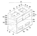
上記の構成を有する本発明のティルト式ケーブルダクトは、その1個のダクト本体に関する限りにおいては、閉断面構造のダクト構造を有する必要がない。後述する図1の例におけるダクト本体はこの構成の具体例であり、上記のとおり前板、底板及び背板を有し、上板を有していない。しかしこの構成においても、複数個のダクト本体を上下に接して配置することによって(図15参照)、上段のダクトの底板が下段のダクトの上板を兼ね、或いは下段のダクト本体の上板が上段のダクト本体の底板を兼ねることとなり、閉断面構造のケーブルダクトを構成することができる。このように、本発明のティルト式ケーブルダクトを設置するときには、隣接する上段と下段のダクト本体の間隔を任意に決定することができ、最も密に配置するときには上段と下段のダクト本体を接しさせて配置することが可能である。 The tilt type cable duct of the present invention having the above-described configuration does not need to have a duct structure having a closed cross section as far as the single duct body is concerned. The duct main body in the example of FIG. 1 described later is a specific example of this configuration, and has a front plate, a bottom plate, and a back plate as described above, and does not have an upper plate. However, even in this configuration, by arranging a plurality of duct bodies in contact with each other (see FIG. 15), the bottom plate of the upper duct also serves as the upper plate of the lower duct, or the upper plate of the lower duct body is It also serves as the bottom plate of the upper duct body, and a cable duct having a closed cross-sectional structure can be configured. As described above, when installing the tilt type cable duct of the present invention, the interval between the adjacent upper and lower duct bodies can be arbitrarily determined, and when arranged most densely, the upper and lower duct bodies are brought into contact with each other. Can be arranged.
ダクト本体の前板はデバイスの取り付け手段を有している。デバイスの取り付け手段としては、DINレールが一般的であるが、DINレールに限らないことは当然であり、例えば、ねじ止めによる直接取り付けを始めとする他の公知の取り付け手段を適用することも可能である。上板は、その前端部にてケーブル敷設部を遮蔽するが、遮蔽状態からケーブル敷設部を露出可能にするために、一部または全部がダクト本体にティルト可能にヒンジ結合するものとする。前板が上板にヒンジ結合されていることによってヒンジ軸を中心に前板を回転させ、ダクト本体の内部を露出させることができ、その結果、ケーブル敷設部に対するケーブルの引き出し、追加、点検等の作業及びそれらに関するチェックが容易になる。 The front plate of the duct body has device attachment means. The device mounting means is generally a DIN rail, but is not limited to the DIN rail. For example, other known mounting means such as direct mounting by screwing may be applied. It is. The upper plate shields the cable laying portion at the front end portion thereof, but a part or all of the upper plate is hinged to the duct body so as to be able to be tilted so that the cable laying portion can be exposed from the shielded state. As the front plate is hinged to the upper plate, the front plate can be rotated around the hinge axis to expose the inside of the duct body. As a result, the cable is drawn out, added, inspected, etc. This makes it easy to check and work on them.
本発明では、少なくとも上記前板又は上板の何れかはケーブルを通すためのケーブル通し窓を有している。ケーブル通し窓は、ダクト本体内部のケーブル敷設部に敷設されるケーブルを引き出し、前板にデバイス取り付け手段を介して取り付けられたデバイスに接続するために、ケーブルを通す窓であり、通常上下に配置されるデバイスの入力側と出力側の端子に、ケーブル敷設部内部からケーブルを上下に引き出して接続することを可能とする。その結果、ケーブルを上下に引き出すために必要とされていた、最小限度2個の縦ダクトも不要となる。また、ケーブルのループを描くような迂回配線(ループ配線)が不要になり、EMC(Electro−Magnetic Compatibility)リスクはループ面積に比例するので、EMC対策上メリットが大きい。 In the present invention, at least one of the front plate and the upper plate has a cable passage window for passing a cable. A cable pass-through window is a window through which a cable is passed in order to pull out a cable laid in the cable laying section inside the duct body and connect it to a device attached to the front plate via a device attachment means, and is usually arranged vertically It is possible to connect the device to the input and output terminals of the device to be drawn up and down from the inside of the cable laying section. As a result, a minimum of two vertical ducts required for pulling the cable up and down are not required. In addition, detour wiring (loop wiring) that draws a cable loop is not required, and the EMC (Electro-Magnetic Compatibility) risk is proportional to the loop area, so there is a great merit for EMC countermeasures.
本発明におけるダクト本体として、デバイスを取り付ける手段を有する前板と、前板の下端部の後方に位置する底板と、前板の上端部の後方に位置する上板と、底板の後端部の上方かつ上板の後端部の下方に位置し、底板と上板の後端部を連絡する背板から成る、閉断面構造を有するものを含むことは当然である。この点は後述する例2以下に示している通りである。そして、前板、底板、上板及び背板の内の任意の板面にも、ケーブルを通すためのケーブル通し窓を具備することができる。なお、本発明において窓とは、四方が囲まれた閉じた開口、切り欠き状の開口を含むものとする。 As a duct body in the present invention, a front plate having means for attaching a device, a bottom plate located behind the lower end portion of the front plate, an upper plate located behind the upper end portion of the front plate, and a rear end portion of the bottom plate It is natural to include one having a closed cross-sectional structure, which is located above and below the rear end portion of the upper plate, and is composed of a back plate that connects the rear end portion of the bottom plate and the upper plate. This point is as shown in Example 2 and later described later. And the cable passage window for letting a cable pass can be provided also in the arbitrary board surfaces in a front board, a bottom board, an upper board, and a back board. In the present invention, the window includes a closed opening surrounded by four sides and a notch-shaped opening.
ダクト本体について、ケーブル敷設方向の端部が閉じた閉端部になっており、上記閉端部と摺動可能な側壁部がティルト可能な前板の端部に設けられ、かつ前板を所望のティルト位置に固定するために、上記閉端部と前板の側壁部に係合部を設けることは望ましい構成である。係合部によって、前板をあらかじめ設定された所望の角度に固定して置き、その間にケーブルダクト本体の内部に関する必要な作業が行えるからである。ダクト本体の前板を所望のティルト位置に固定するためには、ケーブル敷設方向の端部に突出して前板を受け支える受け支え部を設けた構成を取っても良い。また、前板のティルト方向に沿った円弧状の長孔を有する部材をダクト本体又は前板に取り付け、長孔にねじを通して締め付けることで、所望のティルト位置に前板を固定することも可能である。 About the duct body, the end in the cable laying direction is a closed end, the closed end and the slidable side wall are provided at the end of the tiltable front plate, and the front plate is desired In order to fix to the tilt position, it is desirable to provide an engaging portion on the closed end portion and the side wall portion of the front plate. This is because the front plate is fixed at a desired angle set in advance by the engaging portion, and necessary operations relating to the inside of the cable duct main body can be performed in the meantime. In order to fix the front plate of the duct main body at a desired tilt position, a configuration may be adopted in which a receiving support portion is provided that protrudes from an end portion in the cable laying direction and supports the front plate. It is also possible to fix the front plate at the desired tilt position by attaching a member having an arc-shaped long hole along the tilt direction of the front plate to the duct body or front plate and tightening the long hole with a screw. is there.
ダクト本体を鉄、アルミニウム又はそれぞれの合金ないしはその他の金属より成る金属板製とした場合には、密閉構造を取ることと相俟って、良好な電磁遮蔽効果が得られる。ダクト本体を上記金属板製とすることによって内部のケーブル群はシールド(電磁遮蔽)され、EMC対策として有効であり、また、ダクト本体の機械的強度もより高いものとなる。しかし本発明においては、プラスチック製或いはプラスチックと金属複合材製のダクト本体も使用することができる。 When the duct body is made of a metal plate made of iron, aluminum, their respective alloys or other metals, a good electromagnetic shielding effect can be obtained in combination with the sealed structure. By making the duct body made of the above metal plate, the internal cable group is shielded (electromagnetic shielding), which is effective as an EMC countermeasure, and the duct body has higher mechanical strength. However, in the present invention, a duct body made of plastic or plastic and metal composite material can also be used.
また、ダクト本体を背板によって制御盤のキャビネット等の筐体に直接連結すると、それ自体が中板として機能するので、中板が不要になる。なお、中板は図13及び図14に符号pで示した部材であり、従来は不可欠とされていた。また、キャビネット等の筐体が不要な環境では、ダクト本体をそのまま設備機械に抱かせることができる。ダクト本体の取り付け手段として、背板に横長のボルト通し孔を設け、位置調節可能な取り付け手段とすることができる。 Further, when the duct body is directly connected to a housing such as a cabinet of the control panel by the back plate, the mid plate is not necessary because it itself functions as a middle plate. The intermediate plate is a member indicated by symbol p in FIGS. 13 and 14 and has been indispensable in the past. Further, in an environment where a housing such as a cabinet is unnecessary, the duct body can be held in the equipment machine as it is. As a means for attaching the duct body, a laterally long bolt hole is provided on the back plate, and the position can be adjusted.
本発明は上記のように構成されかつ作用するものであり、隣接する上段と下段のダクト本体の間隔を任意に決定することができるから、制御盤内部のように限られた空間の内部を有効に利用することができ、或いは、使用するデバイス種類及び大きさが同じである条件において制御盤などの大きさを小型化可能なティルト式ケーブルダクトを提供することができる。 The present invention is configured and operates as described above, and since the interval between the adjacent upper and lower duct bodies can be arbitrarily determined, the inside of the limited space such as the inside of the control panel is effective. In addition, it is possible to provide a tilt type cable duct capable of reducing the size of a control panel or the like under the condition that the device type and size used are the same.
また、本発明によれば、これまでのケーブルダクトに関する常識を廃して、任意の板面にケーブルを通すためのケーブル通し窓を設けることができ、かつ、どの段のダクト本体からも前板をティルトさせておいて、ケーブルを引き出し、敷設することができるので、ケーブル敷設部に対するケーブルの引き出し、追加、点検等の作業及びそれらに関するチェックを容易化可能なティルト式ケーブルダクトを提供することができる。 Further, according to the present invention, common sense related to cable ducts so far can be abolished, a cable passage window for passing a cable through any plate surface can be provided, and a front plate can be installed from any duct body. Since the cable can be pulled out and laid while being tilted, it is possible to provide a tilt-type cable duct that can facilitate the work of pulling out, adding, and inspecting the cable with respect to the cable laying portion, and checking related thereto. .
また、本発明によれば、上段、下段のダクト本体はケーブル通し窓によって上下につながり得る形態であり、段の違うケーブルダクト同士の連結に従来は必要であった縦ダクトが不要となるから、縦ダクトの大きさ分だけ幅方向のスペースを節約できる。また、ループ配線の不要化によるEMC対策、背面のグリッド配線の実現が可能になる。 Further, according to the present invention, the upper and lower duct bodies can be connected up and down by the cable through window, and the vertical duct that has been conventionally required for connecting the cable ducts at different stages becomes unnecessary. Space in the width direction can be saved by the size of the vertical duct. In addition, it becomes possible to realize EMC countermeasures and grid wiring on the back by eliminating the need for loop wiring.
また、本発明によれば、上記ケーブル配線の効率化によって、試算では30パーセントを超える配線長さの省略が可能になり、配線長さに比例して起こる不具合、特に経年変化によるリスクファクターの著しい低減、生産効率の向上が期待されるほか、制御盤等の小型化によるチェックエリア及び誤認の減少、占有面積の減少、室内から室外等への設置場所の変更等、多くのメリットがある。例えば、制御盤キャビネット等についてみると、その筐体の剛性(機械的強度)は鋼板長さの3乗に反比例するので30パーセントの小型化では、0.7の3乗分の1となり約2.9倍の剛性アップとなるから、剛性を同等とすると仮に2.3ミリ厚の鋼板が必要であった場合にはその下の規格の1.6ミリ厚の鋼板で良いことになり、約30パーセントの筐体重量軽減が実現し、材料費も下がる。 In addition, according to the present invention, the efficiency of the cable wiring makes it possible to omit a wiring length exceeding 30% in a trial calculation, and a problem that occurs in proportion to the wiring length, particularly a risk factor due to secular change is remarkable. In addition to being expected to reduce and improve production efficiency, there are many advantages such as reduced check area and misidentification due to downsizing of control panel, etc., reduction of occupied area, change of installation location from indoor to outdoor, etc. For example, in the case of a control panel cabinet or the like, the rigidity (mechanical strength) of the casing is inversely proportional to the cube of the length of the steel plate. Since the rigidity is increased by a factor of nine, if the same rigidity is required, if a 2.3 mm thick steel plate is required, a 1.6 mm thick steel plate of the standard below may be used. 30% reduction in housing weight is realized and material costs are reduced.
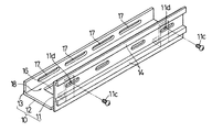
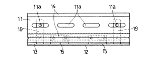
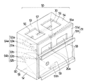
以下図示の実施形態を参照して、本発明をより詳細に説明する。図1〜図5は、本発明に係るティルト式ケーブルダクトの例1を示すもので、例1のダクト本体10は左右方向に細長く形成された任意の長さの前板11、底板12及び上下に短い背板13を有している。前板11はデバイスの取り付け手段14を有しており、その上端部において、ヒンジ部材15を用いて底板12の前端部に結合されており、底板12はケーブルを通すために形成された方形状のケーブル通し窓16を複数個長手方向に有しており、底板12の後端部には背板13の上端部が位置して一体化しており、背板13には取り付け位置調節のために横長に形成したボルト通し孔17が複数個長手方向に設けられている(図2参照)。
Hereinafter, the present invention will be described in more detail with reference to the illustrated embodiments. 1 to 5 show Example 1 of a tilt type cable duct according to the present invention. A
例1のダクト本体10は上板を有していないが、前板11、底板12及び背板13によって囲まれるほぼ方形断面の空間がケーブル敷設部18である。また、背板13をダクト側取り付け部としてダクト本体10を制御盤のキャビネット等の筐体に連結するときに、上段のダクト本体10と下段のダクト本体10を接しさせて配置することによって、下段のダクト本体10の底板12が上段のダクト本体10の底板を兼ねることになる。図1、図2において、19は支持部材であり、ダクト本体10の左右両端部に取り付けられ、ケーブル敷設部18を遮蔽した直立状態にて、前板11を必要に応じて止めねじ11cによりねじ止めし、直立状態に固定することができるように雌ねじ穴11dを有している。
Although the
上記の例1において、デバイスの取り付け手段14はDINレールであり、前板11と一体に形成されている。しかしながら、後述の例と同様に別々に用意されている前板11とデバイス取り付け手段14を一体に形成しても良いことは言うまでもない。なお、11aはケーブル通し窓であり、前板11の左右方向に複数個設けられている。例1の場合、前板11はケーブル敷設部18を遮蔽した図3Bの状態からケーブル敷設部18を露出可能にするために、全部が上記直立状態から前下方へ回転してケーブル敷設部18を開く状態を取り、これが前板11の前方へのティルトと呼ぶ動きに当たる。従って、例1では前板11の前方へのティルトによって、ケーブル敷設部18に対するケーブルの引き出し、点検等の作業に関するチェックを容易に行うことが可能になる。
In Example 1 above, the device attachment means 14 is a DIN rail and is formed integrally with the
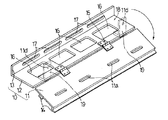
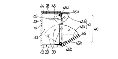
図6〜図8は、本発明に係るティルト式ケーブルダクトの例2を示すもので、例2のダクト本体20は左右方向に細長く形成された任意の長さの前板21、底板22、背板23及び上板24を有している。前板21は幅の狭い前板上部21aと幅の広い前板下部21bの上下に2分されており、それぞれ底板22の前端部と、底板24の前端部にヒンジ部材25a、25bを用いて結合され、また、前板上部21aには切り欠き状のケーブル通し窓26aが設けられており、前板下部21bには左右方向に長いケーブル通し窓26bが複数個設けられている。背板23には取り付け位置調節のためにボルト通し孔27が複数個長手方向に設けられている。
6 to 8 show Example 2 of the tilt type cable duct according to the present invention. The
例2では、底板22及び上板24にもケーブル通し窓28、29が左右方向に複数個設けられており、いずれのケーブル通し窓26a、26b、28、29からもダクト本体内部のケーブル敷設部30に通じることができるように構成されている。さらに例2のダクト本体20は、ケーブル敷設方向の端部が閉じた閉端部31になっている。なお、例2のケーブルダクトでは図示していないが、デバイスの取り付け手段として、例えばねじ止めのための雌ねじ部を前板21に設けることができる。
In Example 2, the
例2において、前板上部21aと前板下部21bには、これらを所望のティルト位置に固定するために、係合部32a、32bを、ダクト本体の両側に設けている。係合部32a、32bとしては、上記閉端部31における前板上部21a、前板下部21bのヒンジ部を中心とした回転範囲の前端部に1箇所の凹部又は凸部33a、33bを設け、前板上部21a、前板下部21bにはそれぞれの左右方向の端部に扇形の側壁部34a、34bを設けるとともに、各側壁部34a、34bには数か所の凸部又は凹部35a、35bを設けて、凹部又は凸部33a、33bと凸部又は凹部35a、35bの凹凸係合によって、開閉位置で固定されるように構成されている。
In Example 2, the front plate
上記凹部又は凸部33a、33bと凸部又は凹部35a、35bの凹凸係合による位置決めによって、前板上部21aと前板下部21bが所望のティルト位置に固定されるもので、それによって前板上部21aと前板下部21bを押さえていなくても、ケーブル敷設部30に対するケーブルの引き出し、点検等の作業に関するチェックを容易に行えるようになる。このティルト角度は90度つまり直角程度開くことが理想であるが、開いたときの作業性と他との抵触を比較考量して、前閉(0度)、半開(30度)、全開(60度)のように設定する。
The front plate
図9〜図10は、本発明に係るティルト式ケーブルダクトの例3を示すものであるが、特に前板下部41bを所望のティルト位置に固定するために、ケーブル敷設方向の端部に突出して前板下部41bを受け支える受け支え部36を設けた例である。よって、例3のダクト本体40は例2のものと同様であり、左右方向に細長く形成された任意の長さの前板41、底板42、背板43及び上板44を有し、前板41は幅の狭い前板上部41aと幅の広い前板下部41bの上下に2分され、それぞれ上板42の前端部と、上板44の前端部にヒンジ部材45a、45bを用いて結合され、かつまた前板上部41aには切り欠き状のケーブル通し窓46aが設けられ、前板下部41bには左右方向に長いケーブル通し窓46bが複数個設けられている。背板43には取り付け位置調節のためにボルト通し孔47が複数個長手方向に設けられている。ケーブル通し窓28、29及びケーブル敷設部30については、例2と同様であるのでそれらの符号を援用して説明に代える。
FIGS. 9 to 10 show a third example of the tilt type cable duct according to the present invention. In particular, in order to fix the front plate
例3における受け支え部36は、ダクト本体40の閉端部37における前端部にて、ヒンジ部を中心とした回転半径方向前上方へ突出する突片部38に設けられており、ティルトして来た前板下部41bをその下面にて受け支えるもので、図示の例では前板下部41bの両側を支えるように設けられている。従って、例3では前閉(0度)及び半開(30度)の位置に凹凸係合による係合部39が設けられていれば良い。なお、例3における前板上部41aは例2と同様に扇形の側壁部48を設けるとともに、上記閉端部37と側壁部48との間に凹凸係合による係合部49を設けておけば良い。また、凹凸係合による係合部39、49は、例2における凹部又は凸部33a、33bと凸部又は凹部35a、35bの凹凸係合と全く同じ構成で良いので、ここでは説明を繰り返さない。
The receiving
図11は、本発明に係る例2のティルト式ケーブルダクトについて、デバイスの取り付け手段58として、DINレールを前板51の下部51bに取り付けた例4を示す。デバイスの取り付け手段58はDINレールとして示され、前板下部51bに取り付けられておりケーブル通し窓は塞がれているが、例1と同様にケーブル通し窓を設けることも当然可能である。前板上部51aについては塞いでしまう必要性はないので、ケーブル通し窓26aを例2、例3と同様に設けておいて良い。他の構成については、例2の場合と同じで良いので要部のみ説明する。ダクト本体50は前板51、底板52、背板53及び上板54を有しており、前板上部51a及び前板下部51bはそれぞれ底板52の前端部と、上板54の前端部にヒンジ部材55a、55bを用いて結合されている。また、ケーブル通し窓56、59は底板52と上板54に設けられ、背板53には取り付け位置調節のためにボルト通し孔57が複数個長手方向に設けられている。
FIG. 11 shows Example 4 in which the DIN rail is attached to the
また、例4において、前板上部51aと前板下部51bには、これらを所望のティルト位置に固定するために、係合部64a、64bを、例2と同様にダクト本体の両側に設けている。係合部64a、64bとして、上記閉端部60における前板上部51a、前板下部51bのヒンジ部を中心とした回転範囲の前端部に1箇所の凹部又は凸部61a、61bを設け、前板上部51a、前板下部51bにはそれぞれの左右方向の端部に扇形の側壁部62a、62bを設けるとともに、各側壁部62a、62bには数か所の凸部又は凹部63a、63bを設けて、凹部又は凸部61a、61bと凸部又は凹部63a、63bの凹凸係合によって、開閉位置で固定されるように構成されている。
Further, in Example 4, the front plate
上記した例2ないし例4では凹凸係合を前板21、41等の固定手段として示しているが、例えば前述したように円弧状の長孔を有する部材をダクト本体又は前板に取り付け、長孔にねじを通して締め付けることによって、所望のティルト位置に前板を固定するような公知の方法を用いて前板21、41等を固定することができる。さらに、ダクト本体20、40等を閉じた状態に、前板21、41等を固定するために、例1に示した支持部材19と、止めねじ11cを用いることができる。
In Examples 2 to 4 described above, the concave / convex engagement is shown as a fixing means for the
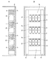
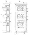
このような構成を有する本発明に係るティルト式ケーブルダクトは、図12に符号A、A′、A″を付して示したように、例えばダクト本体50を背板53によって制御盤のキャビネット等の筐体Cに、ボルト65、ナット66のような固定手段を用いて直接連結し(中板を必要とせずに)、取り付けることができる。上段及び下段のティルト式ケーブルダクトA、A′…を取り付ける間隔Lは広くも狭くも任意に選択することができる。図12の下段に示したように、任意の間隔で筐体Cに取り付けた本発明に係るティルト式ケーブルダクトA、A′…は、前板51bを所望の角度に開いてケーブル敷設部30の内部に敷設されているケーブル68の引き出し、点検等の作業及びそれらに関するチェックを自由に行うことができる。
The tilt type cable duct according to the present invention having such a configuration is shown in FIG. 12 with reference numerals A, A ′, A ″, for example. Can be directly connected (without the need for an intermediate plate) by using fixing means such as
本発明に係るティルト式ケーブルダクトは、デバイス67が邪魔にならないように、ダクト本体10同士を接触させて配置することが可能である(図15参照)。図15において両用ダクトとあるのが本発明に係るティルト式ケーブルダクトA、A′、A″であり、それぞれの前板11にデバイス67を取り付け、各配線69a、69bをケーブル68から前板11のケーブル通し窓11a、11bを経て引き出し、デバイス67に接続している。図15は、本発明による省スペース効果が最大に発揮されている状態を示したものではあるが、図13及び図14と同一寸法で示したキャビネット70の外形と、ティルト式ケーブルダクトA、A′、A″の内部の比較において明らかであるように、本発明によれば従来のキャビネットの内部の正面面積を50パーセント以下に減少可能であることが分かる。
The tilt type cable duct according to the present invention can be arranged with the
この種のケーブルダクトにおいては、閉断面構造を有すること、及び本発明における前板のようなティルトする構造を持っていないこと、などがこれまでの常識であったといえる。これに対して本発明に係るティルト式ケーブルダクトがティルト式の開閉構造を持つということは、これまでの常識に挑戦するものであることになるが、その結果、制御盤内部のように限られた空間の内部を有効に利用してその小型化を図ることができ、ケーブル引き出し経路の画期的変更によってケーブル全長が著しく短縮され、材料コストの削減、故障率の低下、保守の容易化、設置面積の条件が広がる等、多くのメリットを期待できることになるものである。 In this type of cable duct, it can be said that it has been common knowledge so far to have a closed cross-sectional structure and not to have a tilting structure like the front plate in the present invention. On the other hand, the fact that the tilt type cable duct according to the present invention has a tilt type opening and closing structure is a challenge to the common sense so far, but as a result, it is limited to the inside of the control panel. By effectively utilizing the interior of the space, it is possible to reduce the size of the cable, and the total cable length is significantly shortened by a breakthrough change in the cable pulling path, reducing the material cost, reducing the failure rate, making maintenance easier, Many advantages can be expected, such as a wider installation area.
本発明に係るティルト式ケーブルダクトは、例えば、一般産業機械、工作機械、半導体製造工場、通信機器中継局、回転寿司店ないし遊戯施設、あらゆる自動販売機、切符自動改札機の制御盤、或いは各種工場における電源用分電盤などに利用することができる。 The tilt-type cable duct according to the present invention is, for example, a general industrial machine, a machine tool, a semiconductor manufacturing factory, a communication equipment relay station, a rotating sushi restaurant or a play facility, any vending machine, a control panel of an automatic ticket gate, or various It can be used for power distribution boards in factories.
10、20、40、50 ダクト本体
11、21、41、51 前板
12、22、42、52 底板
13、23、43、53 背板
14 デバイス取り付け手段
15a、15b、25a、25b、45a、45b、55a、55b ヒンジ部材
16、26a、26b、28、29、46a、46b、56a、56b ケーブル通し窓
17、27、47、57 ボルト通し孔
18、30 ケーブル敷設部
19 支持部材
24、44、54 上板
31、37、60 閉端部
32a、32b、64a、64b 係合部
33a、33b、61a、61b 凹部又は凸部
34a、34b、62a、62b 側壁部
35a、35b、63a、63b 凸部又は凹部
36 受け支え部
38 突片部
39、49 係合部
67 デバイス
68 ケーブル
69a、69b 配線
70 キャビネット
A、A′、A″ 本発明に係るケーブルダクト
C 筐体
L 間隔
10, 20, 40, 50
Claims (7)
デバイスの取り付け手段を有する前板と、前板の下端部又は上端部の後方に位置する底板又は上板と、底板又は上板の後端部の上方又は下方に位置する背板とを有するダクト本体を具備し、
前板は、底板又は上板の前端部にてケーブル敷設部を遮蔽した状態からケーブル敷設部を露出可能にするために、一部または全部がダクト本体にティルト可能にヒンジ結合されており、
少なくとも上記前板、底板又は上板の何れかはケーブルを通すためのケーブル通し窓を有しているティルト式ケーブルダクト。 A cable duct that is capable of fixing devices to the outside and that constitutes a cable laying portion for laying cables that connect the devices to the inside,
A duct having a front plate having a device attachment means, a bottom plate or an upper plate located behind a lower end portion or an upper end portion of the front plate, and a back plate located above or below the rear end portion of the bottom plate or the upper plate. It has a body,
The front plate is hinged so that the cable laying portion can be exposed from the state in which the cable laying portion is shielded at the front end portion of the bottom plate or the upper plate so that it can be tilted to the duct body.
A tilt type cable duct in which at least one of the front plate, the bottom plate and the upper plate has a cable passage window for passing a cable.
前板、底板、上板及び背板の内の任意の板面には、ケーブルを通すためのケーブル通し窓を有している請求項1記載のティルト式ケーブルダクト。 The duct body includes a front plate having means for attaching the device, a bottom plate located behind the lower end portion of the front plate, an upper plate located behind the upper end portion of the front plate, and above and above the rear end portion of the bottom plate. It is located below the rear end of the plate and has a closed cross-sectional structure consisting of a back plate connecting the rear end of the bottom plate and the upper plate,
The tilt type cable duct according to claim 1, wherein a cable passage window for passing a cable is provided on an arbitrary plate surface among the front plate, the bottom plate, the top plate and the back plate.
請求項1記載のティルト式ケーブルダクト。 The duct body has a closed end where the end in the cable laying direction is closed, the closed end and the slidable side wall are provided at the end of the tiltable front plate, and the front plate is desired. The tilt type cable duct according to claim 1, wherein an engaging portion is provided on the closed end portion and the side wall portion of the front plate in order to fix to the tilt position.
請求項2又は3記載のティルト式ケーブルダクト。 The tilt-type cable according to claim 2 or 3, wherein the duct body has a configuration in which a receiving support portion is provided to project and support the front plate so as to protrude from an end portion in the cable laying direction in order to fix the front plate at a desired tilt position. duct.
請求項1記載のティルト式ケーブルダクト。 2. The tilt type cable duct according to claim 1, wherein the duct body is made of a metal plate made of iron, aluminum, or an alloy thereof, and has a sealed structure in order to obtain an electromagnetic shielding effect.
請求項1記載のティルト式ケーブルダクト。 The tilt type cable duct according to claim 1, wherein the duct body has a structure in which a horizontally long bolt hole is provided on the back plate as means for attaching the duct body.
請求項1記載のティルト式ケーブルダクト。 The tilt type cable duct according to claim 1, wherein a DIN rail is attached to the front plate as a device attachment means.
Priority Applications (1)
| Application Number | Priority Date | Filing Date | Title |
|---|---|---|---|
| JP2008240073A JP5155078B2 (en) | 2008-09-18 | 2008-09-18 | Tilt-type cable duct |
Applications Claiming Priority (1)
| Application Number | Priority Date | Filing Date | Title |
|---|---|---|---|
| JP2008240073A JP5155078B2 (en) | 2008-09-18 | 2008-09-18 | Tilt-type cable duct |
Publications (2)
| Publication Number | Publication Date |
|---|---|
| JP2010074962A true JP2010074962A (en) | 2010-04-02 |
| JP5155078B2 JP5155078B2 (en) | 2013-02-27 |
Family
ID=42206222
Family Applications (1)
| Application Number | Title | Priority Date | Filing Date |
|---|---|---|---|
| JP2008240073A Active JP5155078B2 (en) | 2008-09-18 | 2008-09-18 | Tilt-type cable duct |
Country Status (1)
| Country | Link |
|---|---|
| JP (1) | JP5155078B2 (en) |
Cited By (3)
| Publication number | Priority date | Publication date | Assignee | Title |
|---|---|---|---|---|
| KR101110874B1 (en) * | 2010-12-24 | 2012-02-15 | 삼성중공업 주식회사 | Structure for checking electrical interconnects for ship |
| CN107061188A (en) * | 2016-12-28 | 2017-08-18 | 山东中车风电有限公司 | The threading structure and method of cable in a kind of main shaft in wind power generating set |
| KR102070830B1 (en) * | 2019-09-19 | 2020-01-29 | 주식회사 현이엔지 | shielding structure of electromagnetic waves for distribution line |
Families Citing this family (1)
| Publication number | Priority date | Publication date | Assignee | Title |
|---|---|---|---|---|
| GB2612648A (en) * | 2021-11-09 | 2023-05-10 | Jcc Lighting Products Ltd | Remote emergency lighting packs |
Citations (4)
| Publication number | Priority date | Publication date | Assignee | Title |
|---|---|---|---|---|
| JPS52697U (en) * | 1975-06-23 | 1977-01-06 | ||
| JPS62161529U (en) * | 1986-03-31 | 1987-10-14 | ||
| JPH01170974U (en) * | 1988-05-20 | 1989-12-04 | ||
| JPH05137225A (en) * | 1991-08-31 | 1993-06-01 | Fuaiaaransu Kogyo Kk | Cable duct |
-
2008
- 2008-09-18 JP JP2008240073A patent/JP5155078B2/en active Active
Patent Citations (4)
| Publication number | Priority date | Publication date | Assignee | Title |
|---|---|---|---|---|
| JPS52697U (en) * | 1975-06-23 | 1977-01-06 | ||
| JPS62161529U (en) * | 1986-03-31 | 1987-10-14 | ||
| JPH01170974U (en) * | 1988-05-20 | 1989-12-04 | ||
| JPH05137225A (en) * | 1991-08-31 | 1993-06-01 | Fuaiaaransu Kogyo Kk | Cable duct |
Cited By (4)
| Publication number | Priority date | Publication date | Assignee | Title |
|---|---|---|---|---|
| KR101110874B1 (en) * | 2010-12-24 | 2012-02-15 | 삼성중공업 주식회사 | Structure for checking electrical interconnects for ship |
| CN107061188A (en) * | 2016-12-28 | 2017-08-18 | 山东中车风电有限公司 | The threading structure and method of cable in a kind of main shaft in wind power generating set |
| CN107061188B (en) * | 2016-12-28 | 2023-09-05 | 山东中车风电有限公司 | Threading structure and threading method for cable in main shaft of wind generating set |
| KR102070830B1 (en) * | 2019-09-19 | 2020-01-29 | 주식회사 현이엔지 | shielding structure of electromagnetic waves for distribution line |
Also Published As
| Publication number | Publication date |
|---|---|
| JP5155078B2 (en) | 2013-02-27 |
Similar Documents
| Publication | Publication Date | Title |
|---|---|---|
| JP5155078B2 (en) | Tilt-type cable duct | |
| JP5806276B2 (en) | Modular stationary centrifuge | |
| CA2847271C (en) | Swing out mount | |
| KR101817623B1 (en) | Prefabricated electrical distribution box | |
| KR200250464Y1 (en) | Corner bracket for frames of a switch gear | |
| JP6562755B2 (en) | Switchgear | |
| JP7301146B2 (en) | indoor unit of air conditioner | |
| JP5695942B2 (en) | Assembly case for control panel and assembly method thereof | |
| JPH08172709A (en) | Terminal board | |
| JP2009240124A (en) | Control board and method of assembling same | |
| JP2014166122A (en) | Door structure of distribution board | |
| JP7049896B2 (en) | Distribution board | |
| JP5751000B2 (en) | switchboard | |
| JP2011066160A (en) | Rail opening and closing ductless wiring device | |
| JP5066469B2 (en) | Enclosure | |
| JP2009153327A (en) | Switchboard equipment, wire rack and external connecting method of switchboard equipment | |
| JP6257240B2 (en) | Switchgear housing | |
| JPH0330740Y2 (en) | ||
| JP5463430B2 (en) | Rail opening / closing type ductless wiring device | |
| JP4868320B2 (en) | Electrical equipment storage box device | |
| JP5698605B2 (en) | Equipment storage cabinet | |
| JP2011101498A (en) | Control panel | |
| JPWO2004107520A1 (en) | Switchgear | |
| JP2793377B2 (en) | Switchboard | |
| JPWO2004107521A1 (en) | Switchgear |
Legal Events
| Date | Code | Title | Description |
|---|---|---|---|
| A621 | Written request for application examination |
Free format text: JAPANESE INTERMEDIATE CODE: A621 Effective date: 20100423 |
|
| A977 | Report on retrieval |
Free format text: JAPANESE INTERMEDIATE CODE: A971007 Effective date: 20110811 |
|
| A131 | Notification of reasons for refusal |
Free format text: JAPANESE INTERMEDIATE CODE: A131 Effective date: 20120306 |
|
| A521 | Request for written amendment filed |
Free format text: JAPANESE INTERMEDIATE CODE: A523 Effective date: 20120531 |
|
| TRDD | Decision of grant or rejection written | ||
| A01 | Written decision to grant a patent or to grant a registration (utility model) |
Free format text: JAPANESE INTERMEDIATE CODE: A01 Effective date: 20121113 |
|
| A61 | First payment of annual fees (during grant procedure) |
Free format text: JAPANESE INTERMEDIATE CODE: A61 Effective date: 20121206 |
|
| FPAY | Renewal fee payment (event date is renewal date of database) |
Free format text: PAYMENT UNTIL: 20151214 Year of fee payment: 3 |
|
| R150 | Certificate of patent or registration of utility model |
Free format text: JAPANESE INTERMEDIATE CODE: R150 Ref document number: 5155078 Country of ref document: JP Free format text: JAPANESE INTERMEDIATE CODE: R150 |
|
| R250 | Receipt of annual fees |
Free format text: JAPANESE INTERMEDIATE CODE: R250 |
|
| R250 | Receipt of annual fees |
Free format text: JAPANESE INTERMEDIATE CODE: R250 |
|
| R250 | Receipt of annual fees |
Free format text: JAPANESE INTERMEDIATE CODE: R250 |
|
| R250 | Receipt of annual fees |
Free format text: JAPANESE INTERMEDIATE CODE: R250 |
|
| R250 | Receipt of annual fees |
Free format text: JAPANESE INTERMEDIATE CODE: R250 |
|
| R250 | Receipt of annual fees |
Free format text: JAPANESE INTERMEDIATE CODE: R250 |
|
| R250 | Receipt of annual fees |
Free format text: JAPANESE INTERMEDIATE CODE: R250 |
|
| R250 | Receipt of annual fees |
Free format text: JAPANESE INTERMEDIATE CODE: R250 |
|
| R250 | Receipt of annual fees |
Free format text: JAPANESE INTERMEDIATE CODE: R250 |