JP2010074629A - Packet synchronous switching method - Google Patents
Packet synchronous switching method Download PDFInfo
- Publication number
- JP2010074629A JP2010074629A JP2008240976A JP2008240976A JP2010074629A JP 2010074629 A JP2010074629 A JP 2010074629A JP 2008240976 A JP2008240976 A JP 2008240976A JP 2008240976 A JP2008240976 A JP 2008240976A JP 2010074629 A JP2010074629 A JP 2010074629A
- Authority
- JP
- Japan
- Prior art keywords
- packet
- blade
- voice processing
- tdm
- time
- Prior art date
- Legal status (The legal status is an assumption and is not a legal conclusion. Google has not performed a legal analysis and makes no representation as to the accuracy of the status listed.)
- Granted
Links
Images


Classifications
-
- H—ELECTRICITY
- H04—ELECTRIC COMMUNICATION TECHNIQUE
- H04L—TRANSMISSION OF DIGITAL INFORMATION, e.g. TELEGRAPHIC COMMUNICATION
- H04L49/00—Packet switching elements
- H04L49/55—Prevention, detection or correction of errors
- H04L49/552—Prevention, detection or correction of errors by ensuring the integrity of packets received through redundant connections
-
- H—ELECTRICITY
- H04—ELECTRIC COMMUNICATION TECHNIQUE
- H04L—TRANSMISSION OF DIGITAL INFORMATION, e.g. TELEGRAPHIC COMMUNICATION
- H04L49/00—Packet switching elements
- H04L49/40—Constructional details, e.g. power supply, mechanical construction or backplane
-
- H—ELECTRICITY
- H04—ELECTRIC COMMUNICATION TECHNIQUE
- H04J—MULTIPLEX COMMUNICATION
- H04J3/00—Time-division multiplex systems
- H04J3/02—Details
- H04J3/06—Synchronising arrangements
- H04J3/0635—Clock or time synchronisation in a network
- H04J3/0685—Clock or time synchronisation in a node; Intranode synchronisation
-
- H—ELECTRICITY
- H04—ELECTRIC COMMUNICATION TECHNIQUE
- H04L—TRANSMISSION OF DIGITAL INFORMATION, e.g. TELEGRAPHIC COMMUNICATION
- H04L49/00—Packet switching elements
- H04L49/20—Support for services
- H04L49/205—Quality of Service based
- H04L49/206—Real Time traffic
Abstract
Description
本発明は、異なるプロトコル(通信手順)のシステム/ネットワークを相互接続するためのゲートウェイ装置におけるパケット同期切替方法に関し、例えば、通信事業者向けコンピュータのハードウエア規格であるATCA(Advanced Telecom Computing Architecture)規格等、装置内に搭載されるブレード間接続においてパケットベースによるインタフェースが規定された装置におけるデータ処理タイミングとパケット処理の同期化に関するものである。 The present invention relates to a packet synchronization switching method in a gateway device for interconnecting systems / networks of different protocols (communication procedures), for example, ATCA (Advanced Telecom Computing Architecture) standard, which is a hardware standard for computers for communication carriers. The present invention relates to synchronization of data processing timing and packet processing in a device in which a packet-based interface is defined for connection between blades mounted in the device.
図8は、ATCA規格に則った従来のATCA装置の基本構成を示す概念図である。
このATCA装置は、装置内管理制御を行うシェルフマネージャ1と、搭載されるブレード間の装置内LAN(Local Area Network)のスイッチ(SW)機能を有するSWブレード2−1と、各アプリケーション機能を有するブレード2−2〜2−nと、これら各ブレード2−2〜2−n及びシェルフマネージャ1とSWブレード2−1とを相互に接続するための配線機能を有するバックプレーン3とから構成される。
FIG. 8 is a conceptual diagram showing a basic configuration of a conventional ATCA apparatus conforming to the ATCA standard.
This ATCA device has a
SWブレード2−1〜ブレード2−nまでは、最大16枚のブレードを搭載可能となっており、SWブレード2−1へは、シェルフマネージャ1及び各アプリケーション機能を有するブレード2−2〜2nまでのそれぞれが、装置内LAN3aによるパケット通信を行うために接続されている。シェルフマネージャ1は、各ブレード2−1〜2−nの管理制御のために、マネージメントバス3bにより、SWブレード2−1〜ブレード2−nまでがそれぞれ接続されている。SWブレード2−1〜ブレード2−nまでは、装置内共通のクロック信号を供給するために、クロックバス3cが接続されている。
Up to 16 blades can be mounted on the SW blades 2-1 to 2-n, and the blades 2-1 to 2n having the
SWブレード2−1〜ブレード2−nまでは、必要に応じて共通のクロック信号を使用してデータ処理し、各ブレード2−2〜2−n間のデータの送受信は、SWブレード2−1内の装置内LANスイッチを介してパケットベースのデータ送受信を行う。 The SW blades 2-1 to 2-n process data using a common clock signal as necessary, and data transmission / reception between the blades 2-2 to 2-n is performed by the SW blade 2-1. Packet-based data transmission / reception is performed via an in-device LAN switch.
しかし、なお世の中の通信機器では、装置間又は各ブレード間のデータ送受信に、TDM(Time Division Multiplex;時間分割多重)トラヒックを必要とすることが多くあることから、下記の非特許文献1、2に記載されているように、ATCA規格に準じたTDM信号のパケット化について規格化され、ATCA規格がより広い範囲で適用されるようになってきた。 However, communication devices in the world often require TDM (Time Division Multiplex) traffic for data transmission / reception between devices or between blades. As described in the above, the TDM signal packetization conforming to the ATCA standard has been standardized, and the ATCA standard has been applied in a wider range.
こうした中、ATCA規格の各種装置への適用に際して発生する諸問題への解決方法が提案されている。例えば、下記の特許文献1では、各ブレード2−1〜2−n間でのデータ伝送に関して、パケットベースの装置内LAN3aを使用することによるブレード間データ伝送の遅延による影響を抑えるための方法が提案されている。
Under these circumstances, solutions to various problems that occur when the ATCA standard is applied to various devices have been proposed. For example, in
図9は、従来のゲートウェイ装置の一例を示す概略の構成図である。
なお、図9では、説明の簡略化のために、図8における装置内管理制御を行うシェルフマネージャ1と各ブレード2−1〜2−n間を相互に接続するための配線機能を有するバックプレーン3とが、省略して図示されている。
FIG. 9 is a schematic configuration diagram illustrating an example of a conventional gateway device.
In FIG. 9, for simplicity of explanation, the
図9のゲートウェイ装置4は、例えば、IP(Internet Protocol)ネットワークN1と、SDH(Synchronous Digital Hierarchy;同期デジタルハイアラーキ)ネットワークN2とを相互に接続するための装置である。IPネットワークN1は、IP技術を利用して相互接続されたコンピュータネットワークである。SDHネットワークN2は、ANSI(米国規格協会)で規格化されたSONET(Synchronous Optical NETwork)を元に制定された同期網である。 The gateway device 4 of FIG. 9 is a device for connecting an IP (Internet Protocol) network N1 and an SDH (Synchronous Digital Hierarchy) network N2, for example. The IP network N1 is a computer network interconnected using IP technology. The SDH network N2 is a synchronous network established based on SONET (Synchronous Optical NETwork) standardized by ANSI (American National Standards Institute).
ゲートウェイ装置4は、冗長構成(即ち、同一構成)にある運用系音声処理ブレード5−1及び予備系音声処理部レード5−2等の複数のブレード5−1,5−2,・・・と、SDHネットワークインタフェースブレード6と、制御ブレード7と、スイッチブレード8とを備えている。
The gateway device 4 includes a plurality of blades 5-1, 5-2,..., Such as an active audio processing blade 5-1 and a standby audio processing unit RAID 5-2 in a redundant configuration (that is, the same configuration). SDH
運用系音声処理ブレード5−1及び予備系音声処理部レード5−2は、PKG制御部5aと、パケット(PKT)処理部5b−1、I−TDM(Internal TDM)/TDM変換部5b−2、及びバッファ5b−3を有するI−TDM処理部5bと、音声処理本体5c−1、PKT処理部5c−2、及びPKG保持部5c−3を有する音声処理部5cと、クロック受信部5d等とにより、それぞれ構成されている。SDHネットワークインタフェースブレード6は、PKG制御6a、SDH/I−TDM変換部6b、及びSDH終端部6c等により構成されている。制御ブレード7は、クロック管理部7a、クロック送信部7b、及び装置制御部7c等により構成されている。更に、スイッチブレード8は、PKG制御部8a、及びネットワーク(NW)スイッチ8b等により構成されている。
The active voice processing blade 5-1 and the standby voice processing unit RAID 5-2 include a
この種のゲートウェイ装置4において、冗長構成にある音声処理ブレード5−1,5−2では、運用系音声処理ブレード5−1が、制御部ブレード7から供給される共通クロックを基に音声処理し、NWスイッチ8bを介して接続されるIPネットワークに対してパケットを出力し、又、NWスイッチ8bからSDHネットワークインタフェースブレードを介してSDHネットワークN2に対してデータ出力している。一方、予備系音声処理ブレード5−2は、NWスイッチ8bにより系切替が実施されるまで待機状態にあり、パケット出力を停止している。
In this type of gateway device 4, in the redundant voice processing blades 5-1 and 5-2, the operational voice processing blade 5-1 performs voice processing based on the common clock supplied from the
ATCA規格に則ったゲートウェイ装置4においては、高い信頼性を得るために、搭載されている音声処理ブレード5−1,5−2,・・・間において冗長構成をとることが多い。 In the gateway device 4 conforming to the ATCA standard, in order to obtain high reliability, a redundant configuration is often adopted between the installed voice processing blades 5-1, 5-2,.
冗長構成は、その要求条件により、冗長構成された音声処理ブレード5−1,5−2のうち一方を運用系に設定し、他方を予備系に設定して運用する二重化構成や、同一機能を持つ複数の運用系音声処理ブレード5−1,5−2,・・・に対して、1つの音声処理ブレード(例えば、5−2)を共通の予備系として設定して運用するN+1重化とする構成等をとる。 In the redundant configuration, a redundant configuration in which one of the redundantly configured voice processing blades 5-1 and 5-2 is set as the active system and the other is set as the standby system according to the requirements, and the same function is used. N + 1 duplication in which one voice processing blade (for example, 5-2) is set and operated as a common standby system for a plurality of operational voice processing blades 5-1, 5-2,. The structure to do is taken.
冗長系切替の契機としては、運用系音声処理ブレード5−1に故障が発生した場合はもちろんのことながら、サイレント障害等の防止策として定期的に運用系音声処理ブレード5−1と予備系音声処理ブレード5−2の系切替を実施する場合等がある。 As an opportunity for switching to the redundant system, not only when a failure occurs in the active voice processing blade 5-1, but also as a preventive measure against silent failure, etc., the active voice processing blade 5-1 and the standby voice are regularly used. There is a case where system switching of the processing blade 5-2 is performed.
しかしながら、係る系切替に際して、クロック、フレームパルスを共通としたTDM伝送方式としていた従来のゲートウェイ装置4においては、同期した系切替を容易に実現することができたが、パケットベースとしたデータ伝送方法をとるATCAに則ったブレード間伝送において、パケット出力タイミングを合わせる方法が考慮されていないので、冗長系間のパケット出力タイミングを正確に合わせることができないことから、パケットの欠落や重複を完全に除去することができず、又、パケットに含まれる連続すべきデータの連続性を保つことができないことから、IPネットワークN1及びSDHネットワークN2に接続された通信相手の装置において不連続なパケット及びデータを受信することになり、通信の中断を伴うことになるという課題があった。更に、ゲートウェイ装置4の制御がパケットベースにより実施されるため、系切替指示にタイムラグが発生することで、冗長系間で系切替タイミングを同一にすることができないといった課題があった。 However, in the conventional gateway apparatus 4 which used the TDM transmission method with a common clock and frame pulse at the time of such system switching, the synchronized system switching could be easily realized, but the packet-based data transmission method In the inter-blade transmission conforming to ATCA, the method of matching the packet output timing is not considered, so it is impossible to accurately match the packet output timing between the redundant systems. In addition, since the continuity of the data to be included in the packet cannot be maintained, discontinuous packets and data are not transmitted in the communication partner devices connected to the IP network N1 and the SDH network N2. Will result in interruption of communication. There is a problem in that. Furthermore, since the gateway device 4 is controlled on a packet basis, there is a problem that the system switching timing cannot be made identical between redundant systems due to the occurrence of a time lag in the system switching instruction.
本発明は、異なる第1及び第2のネットワークの間で冗長構成される複数の電子回路基板を有し、前記第1のネットワークから供給されるデータを受信し、データ処理を施した後に前記第2のネットワークへデータ出力するゲートウェイ装置におけるパケット同期切替方法であって、前記ゲートウェイ装置に共通な前記データ処理の基準タイミングと時刻情報を共有し、前記基準タイミングに合せて同期した前記データ処理を実施して同期したパケットを供給し、前記時刻情報に則って前記電子回路基板間の系切替を実施することで、前記パケット出力を同期して切り替えることを特徴とする。 The present invention includes a plurality of electronic circuit boards configured redundantly between different first and second networks, receives data supplied from the first network, performs data processing, and then performs the first processing. A packet synchronization switching method in a gateway device for outputting data to a network of 2, wherein the data processing reference timing and time information common to the gateway device are shared, and the data processing synchronized with the reference timing is performed. The packet output is synchronously switched by supplying synchronized packets and performing system switching between the electronic circuit boards in accordance with the time information.
本発明によれば、冗長系で同じ動作をするように制御された電気回路基板間において、共通する時刻情報を基に系切替を実施することにより、同期し連続した処理データを送受信することが可能となり、パケットのロスや重複のない同期したパケット処理と系切替が可能となる。 According to the present invention, synchronous circuit processing data can be transmitted and received synchronously by performing system switching based on common time information between electrical circuit boards controlled to perform the same operation in a redundant system. It is possible to perform synchronous packet processing and system switching without packet loss and duplication.
本発明を実施するための最良の形態は、以下の好ましい実施例の説明を添付図面と照らし合わせて読むと、明らかになるであろう。但し、図面はもっぱら解説のためのものであって、本発明の範囲を限定するものではない。 The best mode for carrying out the invention will become apparent from the following description of the preferred embodiments when read in conjunction with the accompanying drawings. However, the drawings are only for explanation and do not limit the scope of the present invention.
(実施例1の構成)
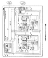
図1は、本発明の実施例1におけるゲートウェイ装置の一例を示す概略の構成図である。
(Configuration of Example 1)
FIG. 1 is a schematic configuration diagram illustrating an example of a gateway device according to the first embodiment of the present invention.
なお、図1では、従来の図9と同様に、説明の簡略化のために、図8における装置内管理制御を行うシェルフマネージャ1と各ブレード2−1〜2−n間を相互に接続するための配線機能を有するバックプレーン3とが、省略して図示されている。
In FIG. 1, as in the case of the conventional FIG. 9, the
本実施例1のゲートウェイ装置9は、従来と同様に、IPネットワークN1と、SDHネットワークN2との間に配置されたATCA規格に則った装置であり、冗長構成される第1、第2の電子回路基板(例えば、音声処理ブレード)10,20を有する複数の音声処理ブレードと、SDHネットワークインタフェースブレード30と、制御ブレード40と、PKG制御部51及びNWスイッチ52を有するスイッチブレード50等とにより構成されている。
The
音声処理ブレード10は、この音声処理ブレード全体を制御するPKG制御部11と、I−TDM処理部12と、音声処理部13と、Label/SN/TS送受信部14と、クロック・基準タイミング受信部15と、PKG内時刻管理部16と、データ処理タイミング管理部17と、chNo./SN/TS送受信部18とを有している。
The
PKG制御部11は、制御ブレード40との装置制御情報の送受信のために信号線10aによりスイッチブレード50と接続され、音声処理ブレード10内部で、I−TDM処理部12と音声処理部13とLabel/SN/TS送受信部14とchNo./SN/TS送受信部18とクロック・基準タイミング受信部15とPKG内時刻管理部16とデータ処理タイミング管理部17とにそれぞれ接続されている。I−TDM処理部12は、PKT処理/転送部12a、I−TDM/TDM変換部12b、及びバッファ12c等により構成されている。このI−TDM処理部12は、信号線10bによりスイッチブレード50と接続され、音声処理ブレード10内部で、音声処理部13とLabel/SN/TS送受信部14とPKG内時刻管理部16とデータ処理タイミング管理部17とに接続されている。
The
音声処理部13は、音声処理本体13a、PKT処理/転送部13b、及びバッファ13c等により構成されている。この音声処理部13は、信号線10dによりスイッチブレード50と接続され、音声処理ブレード10内部で、chNo./SN/TS送受信部18とPKG内時刻管理部16とデータ処理タイミング管理部17に接続されている。クロック・基準タイミング受信部15は、信号線40a,40b,40cにより制御ブレード40と接続され、音声処理ブレード10内部で、PKG内時刻管理部16とデータ処理タイミング管理部17とに接続されている。chNo./SN/TS送受信部18は、信号線10eによりスイッチブレード50と接続され、音声処理ブレード10内部で、PKG内時刻管理部16とデータ処理タイミング管理部17とに接続されている。
The audio processing unit 13 includes an audio processing body 13a, a PKT processing / transfer unit 13b, a
音声処理ブレード20は、音声処理ブレード10と冗長構成(即ち、同一構造及び同一接続)であり、PKG制御部21と、PKT処理/転送部22a、I−TDM/TDM変換部22b、及びバッファ22c等により構成されたI−TDM処理部22と、音声処理本体23a、PKT処理/転送部23b、及びバッファ23c等により構成された音声処理部23と、Label/SN/TS送受信部24と、クロック・基準タイミング受信部25と、PKG内時刻管理部26と、データ処理タイミング管理部27と、chNo./SN/TS送受信部28とを有している。
The
なお、音声処理ブレード10からの信号線10a,10b,10c,10d,10e、及び、音声処理ブレード20からの信号線20a,20b,20c,20d,20eは、説明上線を分けて図示されているが、これらはパケットベースでの伝送であることから、一般的にはその使用帯域に合せてまとめて伝送される作りであって良い。
Note that the
SDHネットワークインタフェースブレード30は、SDHネットワークN2に対するインタフェース機能を有し、PKG制御部31、SDH/I−TDM変換部32、及びSDH終端部33等により構成され、これらが相互に接続されている。PKG制御部31は、信号線30aによりスイッチブレード50に接続され、SDH/I−TDM変換部32は、信号線30bによりスイッチブレード50に接続されている。更に、SDH終端部33は、SDHネットワークN2に接続されている。
The SDH network interface blade 30 has an interface function with respect to the SDH network N2, and includes a
制御ブレード40は、クロック・基準タイミング/装置内時刻管理部41と、クロック・基準タイミング送信部42と、装置制御部43とを有し、装置制御のためにスイッチブレード50に接続されている。制御ブレード40からスイッチブレード50内のNWスイッチ52を介して各ブレードを制御するために、音声処理ブレード10の制御のために信号線10a、声処理ブレード20の制御のために信号線20a、SDHネットワークインタフェースブレード30の制御のために信号線30aがそれぞれ接続されている。又、クロック・基準タイミング、装置内時刻情報の分配(ATCAにおける同期クロックインタフェース)のために、信号線40a,40b,40cが、音声処理ブレード10,20とSDHネットワークインタフェースブレード30とスイッチブレード50とに接続されている。
The control blade 40 includes a clock / reference timing / in-device time management unit 41, a clock / reference timing transmission unit 42, and a
スイッチブレード50において、PKG制御部51及びNWスイッチ52は相互に接続され、そのNWスイッチ52が、音声処理ブレード10,20、SDHネットワークインタフェース30、及び制御部ブレード40に接続されると共に、IPネットワークN1にも接続されている。
In the switch blade 50, the PKG control unit 51 and the
(実施例1のパケット同期切替方法)
本実施例1の図1では、SDHネットワークN2からのSDHフレーム受信によって入力される音声データを、IPネットワークN1へVoIP(Voice over Internet Protocol)パケットで出力するための機能と、IPネットワークN1から受信したVoIPパケットを、SDHネットワークN2へSDHフレームで出力する機能とを有するゲートウェイ装置9の構成が示されている。VoIPとは、音声を各種符号化方式で圧縮しパケットに変換した上でIPネットワークでリアルタイム伝送する技術である。
(Packet synchronous switching method of the first embodiment)
In FIG. 1 of the first embodiment, a function for outputting voice data input by receiving an SDH frame from the SDH network N2 to the IP network N1 as a VoIP (Voice over Internet Protocol) packet, and reception from the IP network N1. A configuration of the
ゲートウェイ装置9内に搭載されているブレード10,20間のデータ転送は、全てパケットベースとなっているため、SDHネットワークインタフェースブレード30では、受信したSDHフレームからの音声データを、非特許文献1、2に示されるI−TDMパケット化し音声処理ブレード10,20へ出力すべく、信号線30bにてスイッチブレード50へ出力する。ここに、I−TDMパケット化周期には、非特許文献1、2に示される1msと125μsの2通りがあり、音声処理の同期化のためにはこれらの同期を取る必要があることが分かる。
Since the data transfer between the
音声処理ブレード10と音声処理ブレード20は、音声処理ブレード10を運用系、音声処理ブレード20を共通の予備系としたN+1冗長構成となっていて、SDHネットワークインタフェースブレード30は、運用系音声処理ブレード10宛てにI−TDMパケットを出力している。
The
運用系音声処理ブレード10は、NWスイッチ52から信号線10bにより受信したI−TDMパケットを、PKT処理/転送部12aで受信し、パケット伝送により発生する到着揺らぎ吸収のためのバッファ12cにおいて揺らぎ吸収した後、I−TDM/TDM変換部12bでI−TDMパケットデータからTDMデータに変換し、音声処理部13へ出力する。音声処理部13内の音声処理本体13aは、入力されるTDMデータをエコーキャンセル等の音声処理を施した後に、PKT処理/転送部13bへ出力する。
The operational
PKT処理/転送部13bは、PKG制御部11により設定された所定の周期に合せてVoIPパケット化し、装置に接続されるIPネットワークN1へ出力すべく、PKG制御部11により設定されたアドレス宛のパケットを信号線10dによりスイッチブレード50内のNWスイッチ52へ出力する。スイッチブレード50は、音声処理ブレード10から受信したパケットをIPネットワークN1へ出力する。
The PKT processing / transfer unit 13b converts the packet into a VoIP packet in accordance with a predetermined period set by the
これとは逆に、IPネットワークN1からのVoIPパケットは、スイッチブレード50内のNWスイッチ52を介して、そのパケットの宛先アドレスに合せて音声処理ブレード10に、信号線10dにより入力される。音声処理ブレード10は、受信したVoIPパケットをPKT処理/転送部13bで受信し、揺らぎ吸収のためのバッファ13cを介して揺らぎ吸収した後、音声処理本体13aへ出力する。音声処理本体13aでは、パケットロス補償等の処理が施され、TDMデータとしてI−TDM処理部12へ出力する。I−TDM処理部12は、I−TDM/TDM変換部12bで受信したTDMデータを、PKG制御部11により指定されたパケット化周期に合せてパケット化し、PKT処理/転送部12aへ出力する。
On the contrary, the VoIP packet from the IP network N1 is input to the
PKT処理/転送部12aは、PKG制御部11により指定されたフロー識別子(Flow ID)、フローバンドル(Flow Bundle)を基にI−TDMパケットヘッダを生成し、SDHネットワークインタフェースブレード30宛にI−TDMパケットを出力すべく、信号線10bによりスイッチブレード50内のNWスイッチ52へ出力する。SDHネットワークインタフェースブレード30は、NWスイッチ52から信号線30bによってSDH/I−TDM変換部32で受信したI−TDMパケットから、SDHフレームフォーマットにデータ変換し、SDH終端部33を介してSDHネットワークN2へ出力する。
The PKT processing / transfer unit 12 a generates an I-TDM packet header based on the flow identifier (Flow ID) and the flow bundle (Flow Bundle) designated by the
音声処理ブレード20は、音声処理ブレード10と同様の構造と接続を有し、通常、装置内において予備系として非運用状態にある。今、系切替により音声処理ブレード10を運用状態から非運用状態にする場合、予備系音声処理ブレード20を冗長系に指定して系切替を実施すものとする。ここに、系切替に際してパケットの欠落や重複を完全に除去するために、音声処理ブレード10と音声処理ブレード20の間で音声処理タイミングとパケット出力タイミングを一致させる必要がある。この要求条件を満たすために、制御ブレード40から出力される同期インタフェースを用いて、装置内時刻を設定し、同期した系切替を実現する方法を以下に示す。
The
ATCA規格においては、同期インタフェースの各クロック信号は、いずれか1つのブレードから出力されるように規定されている。図1のゲートウェイ装置9では、制御ブレード40において装置内基準タイミングを管理する機能を有し、同期クロックインタフェースのための8KHzクロックと19.44MHzクロックとユーザ定義クロックをクロック・基準タイミング/装置内時刻管理部41において生成し、各ブレード10,20に分配するためにクロック・基準タイミング送信部42へ出力する。クロック・基準タイミング送信部42は、接続される複数のブレードの挿抜における他への影響を抑えるためのドライバ回路が構成されている。
The ATCA standard stipulates that each clock signal of the synchronization interface is output from any one blade. The
クロック・基準タイミング/装置内時刻管理部41からの信号線40aの信号は、ATCA規格の同期クロックインタフェースの第1クロックペアである冗長の8KHzシステムクロックであり、信号線40bの信号は、ATCA規格の同期クロックインタフェースの第2クロックペアである冗長の19.44MHzシステムクロックである。信号線40cの信号は、ATCA規格の同期クロックインタフェースの第3クロックペアでユーザ定義クロックであり、本実施例1において、装置内の音声処理タイミングの同期化と、装置内時刻同期のために使用する。
The signal on the
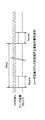
図2−1は、ユーザ定義クロックを音声処理タイミング同期化のために使用する場合の信号波形を示す図である。又、図2−2は、ユーザ定義クロックを音声処理タイミング同期化のために使用する場合の他の信号波形を示す図である。 FIG. 2A is a diagram illustrating signal waveforms when a user-defined clock is used for audio processing timing synchronization. FIG. 2B is a diagram illustrating another signal waveform when the user-defined clock is used for audio processing timing synchronization.
図2−1に示すように、例えば、IPネットワークN1との間で送受信するVoIPパケットのパケット化周期の最大周期を20msとした場合、VoIPパケットが出力されるタイミングを音声処理ブレード10と音声処理ブレード20との間で一致させるために、20ms周期のタイミングを一致させる必要がある。このため、ユーザ定義クロックにおいて20ms周期の基準タイミングを出力することにより、各ブレード10,20においてVoIPパケット化周期のタイミングを一致させる。又、I−TDMのパケット化周期として、1ms又は125μs周期のタイミングを一致させる必要があるが、1ms周期に関しては、前記20ms周期を基にタイミングを一致させることが可能であり、125μs周期については、同期クロックインタフェースの第1クロックペアである8KHzシステムクロックを基に一致させることが可能である。
As shown in FIG. 2A, for example, when the maximum period of the packetization period of a VoIP packet transmitted / received to / from the IP network N1 is set to 20 ms, the timing at which the VoIP packet is output corresponds to the
又、図2−2に示すように、125μs、1ms、20msの各タイミングを多重してユーザ定義クロックに出力することも可能であり、このようにすることにより、より短い周期で基準タイミングの補正が可能となる。 In addition, as shown in FIG. 2-2, it is also possible to multiplex the timings of 125 μs, 1 ms, and 20 ms and output them to the user-defined clock, thereby correcting the reference timing in a shorter cycle. Is possible.
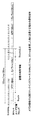
図3−1は、図2−2に示すユーザ定義クロックの後に装置内時刻同期のための装置内時刻情報を多重して送信する場合の信号波形の例を示す図である。なお、図3−2は、ATCA規格の同期クロックインタフェースの第1クロックペアである冗長の8KHzシステムクロックに1ms、20msの各タイミングを多重し、その後に装置内時刻同期のための装置内時刻情報を多重して送信する場合の信号波形の変形例を示す図である。 FIG. 3A is a diagram illustrating an example of a signal waveform in a case where device time information for device time synchronization is multiplexed and transmitted after the user-defined clock shown in FIG. 3-2 multiplexes the timings of 1 ms and 20 ms with the redundant 8 KHz system clock that is the first clock pair of the ATCA standard synchronous clock interface, and then the in-device time information for the in-device time synchronization. It is a figure which shows the modification of the signal waveform in the case of transmitting and multiplexing.
装置内時刻情報としては、ネットワークに接続される機器において機器が持つ時計を正しい時刻へ同期するためのプロトコルであるNTP(Network Time Protocol)と同様の32ビット(bit)情報に加えて、例えば、同期クロックインタフェースの第2クロックペアである19.44MHzシステムクロックによる拡張時刻情報として、同システムクロックによるカウント値を多重している。同カウント値については、上位16bitを125μs毎にカウントアップするカウント値とし、下位16bitを125μsまでのカウント値とする等、システム要件に合せてビットの重み付けを決めることで、より使い易い同期クロックとして用いることが可能である。 As device time information, in addition to 32-bit information similar to NTP (Network Time Protocol), which is a protocol for synchronizing the clock of a device connected to a network to the correct time, for example, As the extended time information by the 19.44 MHz system clock that is the second clock pair of the synchronous clock interface, the count value by the system clock is multiplexed. For the same count value, the upper 16 bits are counted up every 125 μs, and the lower 16 bits are counted up to 125 μs. By determining the bit weights according to the system requirements, the synchronization clock is easier to use. It is possible to use.
図1のゲートウェイ装置9において、音声処理ブレード10では、制御ブレード40から出力される同期インタフェースのための各クロックを、クロック・基準タイミング受信部15で受信し、基板内信号にレベル変換した信号を、PKG内時刻管理部16及びデータ処理タイミング管理部17へ出力する。
In the
PKG内時刻管理部16は、受信したNTPと拡張時刻情報(Ex-Time)を基に、制御ブレード40で管理する装置管理時刻と同じ時刻を管理し、後述するI−TDMパケット同期化のためにLabel/SN/TS送受信部14へ、VoIPパケット同期化のためにchNo./SN/TS送受信部18へ、それぞれ時刻情報を出力する。データ処理タイミング管理部17は、音声処理タイミング同期化のためにパケット化周期を制御ブレード40で管理する基準タイミングに一致させ、音声処理タイミングをI−TDM処理部12、Label/SN/TS送受信部14、chNo./SN/TS送受信部18及び音声処理部13へそれぞれ出力する。
The in-PKG
音声処理ブレード20、SDHネットワークインタフェースブレード30、及びスイッチブレード50においても、同様に制御ブレード40からの同期インタフェースのためのクロックを用いて装置管理時刻と同じ時刻を管理し、音声処理タイミング同期化のためにパケット化周期を制御ブレード40で管理する基準タイミングに一致させる。
Similarly, in the
以上により、装置内の各ブレードで統一した時刻情報を管理し、音声処理タイミングを統一することができる。 As described above, the time information unified by each blade in the apparatus can be managed, and the voice processing timing can be unified.
この状態において、音声処理ブレード10と音声処理ブレード20の系切替動作について詳細に述べる。
In this state, the system switching operation between the
図4は、制御ブレード40と音声処理ブレード10と音声処理ブレード20の動作シーケンスの概要を示す図である。
FIG. 4 is a diagram showing an outline of an operation sequence of the control blade 40, the
先ず、制御ブレード40は、音声処理ブレード10の冗長系ブレードとして音声処理ブレード20を選択する。音声処理ブレード20は、制御ブレード40により音声処理ブレード10と同様のシステム設定となるように、音声処理ブレード10に既に設定されているシステム設定内容が設定される。これにより、音声処理ブレード20は、音声処理ブレードの冗長系として待機状態となる。以降系切替が完了するまで、新たなシステム設定内容については、制御ブレード40から音声処理ブレード10と音声処理ブレード20の両方に同じ設定が行われ、音声処理ブレード10と音声処理ブレード20のシステム設定状態を常に一致させる。
First, the control blade 40 selects the
制御ブレード40は、システム設定状態が一致した時点で、音声処理ブレード10に対して音声処理ブレード20との間でI−TDMパケットとVoIPパケットに関する系の同期化処理を実施するように指示する(I−TDM/VoIP同期化指示)。音声処理ブレード10は、制御ブレード40より系の同期化指示を受けた場合、冗長系として指定された音声処理ブレード20に対して、I−TDMパケット化のために必要な連続するデータであるシーケンス番号とタイムスタンプを同期化パケットにより通知する(I−TDM同期化パケット送出)。
When the system setting state matches, the control blade 40 instructs the
図5−1は、I−TDM同期化パケットフォーマットの例を示す図である。
先ず、パケット識別のためにI−TDM同期化指示情報があり、続いてI−TDMパケットに関する情報が続く。I−TDMの1つのフレームのソースノード識別のための フローバンドル(Flow Bundle)とそれに付随するタイムスタンプ(Time stamp)があり、同フレーム内に多重するパケットのシーケンス番号(Sequence Number)とフロー識別子(Flow ID)がある。同様に、多重されるパケットがある場合、シーケンス番号(Sequence Number)とフロー識別子(Flow ID)が続く。又、以降新たなフローバンドル(Flow Bundle)に付随する同様な情報が、全体のパケット長の最大値範囲内で続いても良い。フレームの最後には、前記各フローバンドル(Flow Bundle)のI−TDMパケットを出力した時点にラッチされたNTPの値と拡張時刻情報がある。
FIG. 5A is a diagram illustrating an example of an I-TDM synchronization packet format.
First, there is I-TDM synchronization instruction information for packet identification, followed by information on I-TDM packets. There is a flow bundle (Flow Bundle) for identifying the source node of one frame of I-TDM and a time stamp (Time stamp) associated therewith, and the sequence number and flow identifier of packets multiplexed in the same frame (Flow ID). Similarly, when there are packets to be multiplexed, a sequence number (Sequence Number) and a flow identifier (Flow ID) follow. In addition, similar information associated with a new flow bundle (Flow Bundle) may be continued within the maximum value range of the entire packet length. At the end of the frame, there are an NTP value and extended time information latched when the I-TDM packet of each flow bundle (Flow Bundle) is output.
このパケットを受信した予備系音声処理ブレード20は、前記装置内時刻情報と音声処理タイミングが一致していることから、自ブレード内で管理している装置時刻情報と、受信したI−TDM同期化パケットのNTP値と拡張時刻情報(Ex-Time)から、現在処理している音声のI−TDMパケットのフレーム情報を運用系の音声処理ブレード10と一致させることができ、次に出力するI−TDMパケットを音声処理ブレード10と音声処理ブレード20で同じ内容のI−TDMパケットとすることができる。
The standby
図5−2は、I−TDM同期化を示す概念図である。
時刻t0において、運用系音声処理ブレード10から、フロー識別子(Flow ID)=0x000001、タイムスタンプ(Time stamp)=0x00C8、シーケンス番号(Sequence Number)=0x01で、NTP及びEx-Timeが時刻t0の内容のI−TDM同期化パケットが送出され、スイッチブレード50経由による遅延時間経過後の時刻t1近辺で、予備系音声処理ブレード20で受信されている。予備系音声処理ブレード20は、受信したパケットの内容から次のI−TDMパケット出力タイミング時刻t2において出力するフロー識別子(Flow ID)=0x000001のI−TDMパケットについて、その内容がタイムスタンプ(Time stamp)=0x0258(1msパケットなので1ms毎に0x00C8ずつ加算される)、シーケンス番号(Sequence Number)=0x03となることを知り得、時刻t2のタイミングにおいて出力されるI−TDMパケット以降、運用系音声処理ブレード10から出力されるI−TDMパケットと予備系音声処理ブレード20から出力されるI−TDMパケットの内容が一致する。
FIG. 5-2 is a conceptual diagram illustrating I-TDM synchronization.
At time t0, from the active
但し、実際にI−TDMパケットを出力するのは運用系である音声処理ブレード10だけであり、音声処理ブレード20は待機状態である間、SDHネットワークインタフェースブレード30宛てにはI−TDMパケットを出力しない。
However, only the active
同様に、VoIPパケット化のために必要な連続するデータであるシーケンス番号(Sequence Number)とタイムスタンプ(Time stamp)をVoIP同期化パケットにより通知する(VoIP同期化パケット送出)。 Similarly, a sequence number (Sequence Number) and time stamp (Time stamp), which are continuous data necessary for VoIP packetization, are notified by a VoIP synchronization packet (VoIP synchronization packet transmission).
図5−3は、VoIP同期化パケットフォーマットの例を示す図である。
先ず、パケット識別のために同期化指示情報があり、続いてVoIPパケットに関する情報がある。チャネル番号(Channel No.)とそれに付随するシーケンス番号(Sequence Number)とタイムスタンプ(Time stamp)が続く。複数のチャネル処理を実施している場合には、それぞれのチャネル番号(Channel No.)について同様の情報が続く。フレームの最後には、前記各チャネル(Channel)のVoIPパケットを出力した時点にラッチされた音声処理タイミングのNTP値と拡張時刻情報(Ex-Time)がある。このパケットを受信した音声処理ブレード20は、装置内時刻情報と音声処理タイミングが一致していることから、自ブレード内で管理している装置時刻情報と、受信したパケットのNTP値と拡張時刻情報(Ex-Time)から、現在処理している音声のVoIPパケットのフレーム情報を運用系の音声処理ブレード10と一致させることができ、次のVoIPパケット出力タイミングに出力するVoIPパケットを、音声処理ブレード10と音声処理ブレード20で同じ内容のVoIPパケットとすることができる。但し、実際にVoIPパケットを出力するのは運用系である音声処理ブレード10だけであり、音声処理ブレード20は待機状態である間、IPネットワークN1宛てにはVoIPパケットを出力しない。
FIG. 5C is a diagram illustrating an example of a VoIP synchronization packet format.
First, there is synchronization instruction information for packet identification, followed by information on VoIP packets. A channel number (Channel No.), an associated sequence number (Sequence Number) and a time stamp (Time stamp) follow. When a plurality of channel processes are performed, similar information follows for each channel number (Channel No.). At the end of the frame, there are an NTP value of voice processing timing and extended time information (Ex-Time) latched when the VoIP packet of each channel (Channel) is output. The
音声処理ブレード20は、I−TDM同期化パケットとVoIP同期化パケットを受信し、音声処理ブレード10との同期化が完了した時点で、制御ブレード40に対して同期化完了を通知する(I−TDM/VoIP同期化完了通知)。
The
制御ブレード40は、前記音声処理ブレード10への系の同期化指示以降、音声処理ブレード10と音声処理ブレード20の同期化処理中における同期化情報の不一致を回避するため、音声処理ブレード20から同期化完了通知があるまで、新たなパケットのパス設定を禁止しておく。
After the synchronization instruction of the system to the
又、音声処理ブレード10と音声処理ブレード20の音声処理状態の不一致による系切替時の音声の違和感を排除するために、系切替以前に予め予備系の音声処理ブレード20に対して、音声処理ブレード10に入力しているI−TDMパケット及びVoIPパケットと同様のパケットを入力し、エコーキャンセラ等の音声処理状態をほぼ一致させておく必要がある。そのため、運用系音声処理ブレード10は、制御ブレード40から系の同期化指示を受けた場合、冗長系として指定された予備系音声処理ブレード20に対して、SDHネットワークインタフェースブレード30から受信するI−TDMパケットと、IPネットワークN1から受信するVoIPパケットを転送するように動作する。
In addition, in order to eliminate the uncomfortable feeling of voice at the time of system switching due to a mismatch between the voice processing states of the
予備系音声処理ブレード20は、転送されてきたパケットを音声処理ブレード10の動作と同様に、SDHネットワークインタフェースブレード30から受信するI−TDMパケットと、IPネットワークN1から受信するVoIPパケットとして、音声処理をし、エコーキャンセラの収束動作等、音声処理状態を運用系音声処理ブレード10の音声処理状態に近づける動作をする。
Similarly to the operation of the
次に、制御ブレード40は、音声処理ブレード20から同期化完了通知を受信した場合、運用系音声処理ブレード10、予備系音声処理ブレード20、及びSDHネットワークインタフェースブレード30に対して、系切替指示パケットを出力する(系切替指示)。
Next, when receiving a synchronization completion notification from the
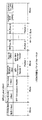
図6は、系切替指示パケットフォーマットの例を示す図である。
先ず、パケット識別のために系切替指示情報があり、続いて切替対象となる運用系ブレードの同期識別子IDと予備系ブレードの同期識別子IDを示し、続いて装置内管理時刻を基にした切替タイミングを示す。ここでは、同一機能を有するブレードを搭載した場合のブレード種別を行うために同期識別子IDを用いたが、切替対象となるブレードの物理アドレスやIPアドレス値を直接指定しても良い。
FIG. 6 is a diagram illustrating an example of a system switching instruction packet format.
First, there is system switching instruction information for packet identification, followed by the synchronization identifier ID of the active blade to be switched and the synchronization identifier ID of the standby blade, and then switching timing based on the in-device management time Indicates. Here, the synchronization identifier ID is used to perform the blade type when the blades having the same function are mounted, but the physical address and IP address value of the blade to be switched may be directly specified.
図7−1は、系切替時のI−TDMパケットの流れを示す図である。
例えば、I−TDMパケットのパケット化周期を1msとする。運用系音声処理ブレード10は、時刻t0において、シーケンス番号SN=100、タイムスタンプTS=800の値を示すI−TDMパケットをSDHネットワークインタフェースブレード30宛てに出力する。同様に、予備系音声処理ブレード20は、前記同期化パケット受信時以降運用系から予備系へ受信パケットを転送する動作により、受信したVoIPパケットを基に音声処理してI−TDMパケットの生成を行うが、自系は待機状態であるためSDHネットワークインタフェースブレード30宛てにI−TDMパケットを出力しない。
FIG. 7A is a diagram illustrating a flow of an I-TDM packet during system switching.
For example, the packetization period of the I-TDM packet is 1 ms. The active
運用系音声処理ブレード10から出力されたパケットは、スイッチブレード50を経由することによる遅延時間経過後、SDHネットワークインタフェースブレード30に入力される。一方、SDHネットワークインタフェースブレード30は、時刻t0において、運用系である音声処理ブレード10宛てにシーケンス番号SN=200、タイムスタンプTS=2000の値を示すI−TDMパケットを出力している。次のI−TDMパケット送出タイミングである時刻t1においては、シーケンス番号SN、タイムスタンプTSがそれぞれ更新されたパケットが時刻t0同様に出力される。
The packet output from the operational
次に、前記系切替指示パケットの切替タイミングがtchangeの値であった場合、時刻tchangeにおいて、運用系音声処理ブレード10は、今までSDHネットワークインタフェースブレード30宛てに出力していたI−TDMパケットの出力を停止し、音声処理ブレード10は待機状態となる。代わって予備系待機状態であった音声処理ブレード20は、受信した系切替パケット内容から、同時刻において自身を運用系運用状態とし、今まで音声処理ブレード10がSDHネットワークインタフェースブレード30宛てに出力していたI−TDMパケットを引き継ぎ、前記I−TDM同期化パケットの受信処理によりシーケンス番号SN、タイムスタンプ値TSが連続した値となるシーケンス番号SN=102、タイムスタンプTS=1200の値を持ったI−TDMパケットをSDHネットワークインタフェースブレード30宛てに出力する。これにより、音声処理ブレード10,20においてパケットロスやパケット重複を発生させることなく、送信I−TDMパケットの同期系切替が完了する。
Next, when the switching timing of the system switching instruction packet is the value of tchange, the active
SDHネットワークインタフェースブレード30は、受信した系切替パケット内容から、宛先音声処理ブレード10,20の系切替が実施されることを通知され、系切替指示パケットの切替タイミングがtchangeの値であった場合、時刻tchangeにおいて今まで運用系音声処理ブレード10宛てに出力していたI−TDMパケットを、新しく運用系となった音声処理ブレード20宛てに切り替えて、シーケンス番号SN=202、タイムスタンプTS=2400の値を示すI−TDMパケットを出力する。これにより、SDHネットワークインタフェースブレード30において、宛先となる音声処理ブレード10,20の系切替タイミングに合せた出力パケットの宛先変更が可能となる。
When the SDH network interface blade 30 is notified from the received system switching packet content that the system switching of the destination
しかし、スイッチブレード50を経由してパケット伝送されることから、系切替直前に音声処理ブレード10宛てに出力したI−TDMパケット(SN=201、TS=2200)は、系切替完了後に既に予備系待機状態となった音声処理ブレード10に到着し、新たに運用系運用状態となった音声処理ブレード20にパケットが到着しなくなることがある。この問題を回避するために、系切替パケットによる切替時刻tchange後、パケット到着遅延を考慮した一定時間ttransfer1は、予備系待機状態となった音声処理ブレード10に到着するI−TDMパケットを、新しく運用系運用状態となった音声処理ブレード20宛てに転送する動作をすることにより、SDHネットワークインタフェースブレード30からのI−TDMパケットをロスなく、新たに運用系となった音声処理ブレード20で受信することが可能となる。ここに音声処理ブレード10は、系切替パケット指示の内容により、冗長系となった音声処理ブレード20のIDからその宛先アドレスは既知である。
However, since the packet is transmitted via the switch blade 50, the I-TDM packet (SN = 201, TS = 2200) output to the
予備系待機状態となった音声処理ブレード10は、パケット到着遅延を考慮した一定時間ttransfer1経過後、その状態を非運用状態として系切替を完了する。又、SDHネットワークインタフェースブレード30は、系切替パケット指示の内容により、事前に音声処理ブレード10,20の系切替により受信するI−TDMパケットの送信元アドレス等の情報が変更になることを知っておく必要があり、受信I−TDMパケット上記情報が変更されることにより、音声処理の不連続が発生しないようにしておく必要がある。
The
図7−2は、系切替時のVoIPパケットの流れを示す図である。
例えば、VoIPパケットのパケット化周期を20msとする。運用系音声処理ブレード10は、時刻t10において、シーケンス番号SN=5、タイムスタンプTS=320の値を示すIPネットワークN1の先に位置する通信相手の宛先アドレスを指定したVoIPパケットを、IPネットワークN1へ出力する。同様に、予備系音声処理ブレード20は、前記同期化パケット受信時以降運用系から予備系へ受信パケットを転送する動作により、受信したI−TDMパケットを基に音声処理してVoIPパケットの生成を行うが、自系は待機状態であるためIPネットワークN1へVoIPパケットを出力しない。IPネットワークN1の先に位置する通信相手の装置には、ネットワーク伝送遅延を持って受信されている。
FIG. 7B is a diagram illustrating a flow of the VoIP packet at the time of system switching.
For example, the packetization period of the VoIP packet is 20 ms. At time t10, the active
一方、IPネットワークN1の先に位置する通信相手からは、同様にパケット化周期20msで運用系音声処理ブレード10宛てにシーケンス番号SN=100、タイムスタンプTS=1600を示すVoIPパケットが出力されている。同様に、ネットワーク伝送遅延を持って音声処理ブレード10に入力されている。予備系音声処理ブレード20は、音声処理同期化のために、運用系音声ブレード10から転送されるVoIPパケットを受信して音声処理を行う。次のVoIPパケット送出タイミングである時刻t11においては、シーケンス番号SN、タイムスタンプTSがそれぞれ更新されたパケットが、時刻t10同様に出力される。
On the other hand, a VoIP packet indicating the sequence number SN = 100 and the time stamp TS = 1600 is output from the communication partner positioned ahead of the IP network N1 to the active
次に、前記系切替指示パケットの切替タイミングがtchangeの値であった場合、時刻tchangeにおいて、運用系音声処理ブレード10は、前記系切替パケット内容から、同時刻において今までIPネットワークN1宛てに出力していたVoIPパケットの出力を停止し、音声処理ブレード10が待機状態となる。代わって予備系待機状態であった音声処理ブレード20は、受信した系切替パケット内容から、同時刻において自身を運用系運用状態とし、今まで運用系音声処理ブレード10がIPネットワークN1宛てに出力していたVoIPパケットを引き継ぎ、前記VoIP同期化パケットの受信処理により、シーケンス番号SN、タイムスタンプ値TSが連続した値となるSN=7、TS=640の値を持ったVoIPパケットを、IPネットワークN1宛てに出力する。これにより、音声処理ブレード10,20において、パケットロスやパケット重複を発生させることなく、送信VoIPパケットの同期した系切替が完了する。
Next, when the switching timing of the system switching instruction packet is the value of tchange, at time tchange, the active
制御ブレード40は、IPネットワークN1の先に位置する通信相手装置に対して、音声処理ブレード10,20の系切替完了時点で、音声処理ブレード10,20の系切替が実施されたことを通知すると共に、通信相手装置出力VoIPパケットの宛先アドレスを変更するように指示する宛先変更指示パケットを出力する。ここに、宛先変更指示パケットの到着以前に、既に音声処理ブレード10,20の系切替完了により新しく運用系となった音声処理ブレード20からVoIPパケットが入力されることがある。このためIPネットワークN1の先に位置する通信相手の装置については、通信確立設定時点等、事前に音声処理ブレード10,20の系切替により受信するVoIPパケットの送信元アドレス、同期識別子ID等の情報が変更になることを通知しておき、受信VoIPパケット上記情報が変更されることにより音声処理の不連続が発生しないようにしておく必要がある。
The control blade 40 notifies the communication partner device positioned ahead of the IP network N1 that the system switching of the
通信相手の装置は、宛先変更指示パケットを受信し、自身の出力するVoIPパケットの宛先アドレスを、新しく運用系となった音声処理ブレード20宛てに変更して出力する。しかし、ネットワーク伝送遅延の影響により、音声処理ブレード10に、前記系切替パケットに示された切替タイミングtchange以降も通信相手装置からVoIPパケットが到着することになり、新しく運用系となった音声処理ブレード20がVoIPパケットを受信できない問題が発生する。
The communication partner apparatus receives the destination change instruction packet, changes the destination address of the VoIP packet output by itself, to the
この問題を回避するために、系切替パケットによる切替時刻tchange後、パケット到着遅延を考慮した一定時間ttransfer2は、予備系待機状態となった音声処理ブレード10に到着するVoIPパケットを、新しく運用系運用状態となった音声処理ブレード20宛てに転送する動作をすることにより、IPネットワークN1からのVoIPパケットをロスなく、新たに運用系となった音声処理ブレード20で受信することが可能となる。予備系待機状態となった音声処理ブレード10は、パケット到着遅延を考慮した一定時間ttransfer2経過後、その状態を非運用状態として系切替を完了する。ここに音声処理ブレード10においては、系切替パケット指示の内容により、冗長系となった音声処理ブレード20の同期識別子IDからその宛先アドレスは既知である。
In order to avoid this problem, after the switching time tchange by the system switching packet, for a certain time ttransfer2 considering the packet arrival delay, a new VoIP packet arriving at the
(実施例1の効果)
本実施例1によれば、次の(A)、(B)のような効果がある。
(Effect of Example 1)
According to the first embodiment, there are the following effects (A) and (B).
(A) 装置内で共通とするクロックを基に装置内の時刻情報と、音声処理に必要な処理タイミングを、実装される各ブレードにおいて共通にし、冗長構成にある音声処理ブレード10と20の間で、それぞれ受信するIPネットワークN1からのVoIPパケットと、SDHネットワークインタフェースブレード30から受信するI−TDMパケットを、お互いに受け渡し、運用系に設定されたブレードから出力するパケットの内容のうち、連続する必要のあるパラメータであるシーケンス番号SNとタイムスタンプTS値を、出力タイミングに一致した共通の時刻情報と共に受け渡すことで、冗長系で同じ動作をするように制御された音声処理ブレード10,20において、共通する時刻情報を基に系切替を実施することにより、同期し連続した音声処理データを送受信することが可能となり、パケットのロスや重複のない同期したパケット処理と系切替が可能となる。
(A) Based on a clock that is common within the apparatus, the time information in the apparatus and the processing timing necessary for audio processing are made common among the mounted blades, and between the
(B) 系切替タイミングについて、共通する時刻情報を基に系切替を実施することにより、冗長系で時間差のない系切替タイミングを実現することが可能となり、パケットのロスや重複のない同期した系切替が可能となる。 (B) By performing system switching based on common time information for system switching timing, it becomes possible to realize system switching timing with no time difference in a redundant system, and a synchronized system without packet loss or duplication. Switching is possible.
(変形例)
本発明は、上記実施例1に限定されず、種々の利用形態や変形が可能である。この利用形態や変形例としては、例えば、次の(1)〜(3)のようなものがある。
(Modification)
The present invention is not limited to the first embodiment, and various usage forms and modifications are possible. For example, the following forms (1) to (3) are used as the usage form and the modified examples.
(1) 実施例1では、音声処理ブレード10,20とSDHネットワークインタフェースブレード30の間のパケットをI−TDMとした例とし、IPネットワークN1との間のパケットをVoIPパケットとしたが、これに代わるパケット方式とし、同様にパケットの内容で連続する必要のあるパラメータを音声処理ブレード間で受け渡すことで、連続した値を取るようにして同期したパケット処理としても良い。又、SDHネットワークN2に代えて、他のIPネットワークを適用することも可能である。
(1) In the first embodiment, the packet between the
(2) 実施例1では、ATCA規格に則って同期クロックのユーザ定義クロックを用いて音声処理同期化のための基準タイミングと装置内時刻情報を共有するようにした例を示したが、ATCA規格に関することなく、図3−2に示すように、基準タイミングと装置内時刻情報を多重した信号を用いて、音声処理同期化のための基準タイミングと装置内時刻情報を共有するようにしても良い。このようにすることで、装置内の配線リソースをより有効に使用することが可能となる。 (2) In the first embodiment, the example in which the reference timing for synchronizing the audio processing and the time information in the apparatus are shared using the user-defined clock of the synchronization clock in accordance with the ATCA standard is shown. Without reference, as shown in FIG. 3B, the reference timing and the in-device time information for audio processing synchronization may be shared using a signal obtained by multiplexing the reference timing and the in-device time information. . By doing in this way, it becomes possible to use the wiring resource in an apparatus more effectively.
(3) 実施例1のゲートウェイ装置9は、図示以外の構成に変更しても良い。又、実施例1では、冗長構成にある音声処理ブレード10,20間でのパケット同期切替方法について説明したが、本発明は、音声以外の映像等の他のデータ処理を行うデータ処理ブレード間でのパケット同期切替方法についても適用可能である。この場合、ゲートウェイ装置9内には、データ処理ブレードに適合した構成のインタフェースブレード等を設ければ良い。
(3) The
9 ゲートウェイ装置
10,20 音声処理ブレード
30 SDHネットワークインタフェースブレード
40 制御ブレード
50 スイッチブレード
N1 IPネットワーク
N2 SDHネットワーク
9
Claims (4)
前記ゲートウェイ装置に共通な前記データ処理の基準タイミングと時刻情報を共有し、前記基準タイミングに合せて同期した前記データ処理を実施して同期したパケットを供給し、前記時刻情報に則って前記電子回路基板間の系切替を実施することで、前記パケット出力を同期して切り替えることを特徴とするパケット同期切替方法。 A plurality of electronic circuit boards configured redundantly between different first and second networks, receiving data supplied from the first network, performing data processing, and then to the second network; A packet synchronous switching method in a gateway device for outputting data,
The data processing reference timing and time information common to the gateway device are shared, the data processing synchronized with the reference timing is performed, and a synchronized packet is supplied, and the electronic circuit according to the time information A packet synchronous switching method, wherein the packet output is switched synchronously by performing system switching between substrates.
前記パケットの連続するデータを前記電子回路基板の冗長系間で共通にすることで、前記パケット出力を同期して切り替えることを特徴とするパケット同期切替方法。 The packet synchronization switching method according to claim 1, further comprising:
A packet synchronous switching method, wherein the packet output is switched synchronously by making the continuous data of the packets common among redundant systems of the electronic circuit board.
前記電子回路基板における前記パケットの冗長系間で、相互に入力した前記パケットを転送する機能を備え前記入力パケットを共有することで、前記系切替時における前記入力パケットのロスを回避することを特徴とするパケット同期切替方法。 The packet synchronization switching method according to claim 1 or 2, further comprising:
The redundant function of the packet on the electronic circuit board is provided with a function of transferring the packet input to each other to share the input packet, thereby avoiding the loss of the input packet at the time of switching the system. Packet synchronous switching method.
Priority Applications (2)
| Application Number | Priority Date | Filing Date | Title |
|---|---|---|---|
| JP2008240976A JP5088281B2 (en) | 2008-09-19 | 2008-09-19 | Packet synchronous switching method and gateway device |
| US12/461,609 US9401878B2 (en) | 2008-09-19 | 2009-08-18 | Packet synchronization switching method and gateway device |
Applications Claiming Priority (1)
| Application Number | Priority Date | Filing Date | Title |
|---|---|---|---|
| JP2008240976A JP5088281B2 (en) | 2008-09-19 | 2008-09-19 | Packet synchronous switching method and gateway device |
Publications (2)
| Publication Number | Publication Date |
|---|---|
| JP2010074629A true JP2010074629A (en) | 2010-04-02 |
| JP5088281B2 JP5088281B2 (en) | 2012-12-05 |
Family
ID=42037623
Family Applications (1)
| Application Number | Title | Priority Date | Filing Date |
|---|---|---|---|
| JP2008240976A Active JP5088281B2 (en) | 2008-09-19 | 2008-09-19 | Packet synchronous switching method and gateway device |
Country Status (2)
| Country | Link |
|---|---|
| US (1) | US9401878B2 (en) |
| JP (1) | JP5088281B2 (en) |
Cited By (3)
| Publication number | Priority date | Publication date | Assignee | Title |
|---|---|---|---|---|
| JP2012518312A (en) * | 2009-02-13 | 2012-08-09 | アルカテル−ルーセント | Packet sequence number synchronization for line card redundancy |
| JP2013074514A (en) * | 2011-09-28 | 2013-04-22 | Fujitsu Ltd | Switch device and switch method |
| US9236968B2 (en) | 2010-12-03 | 2016-01-12 | Fujitsu Limited | Communication device and communication method |
Families Citing this family (2)
| Publication number | Priority date | Publication date | Assignee | Title |
|---|---|---|---|---|
| ES2659773T3 (en) * | 2013-03-15 | 2018-03-19 | Vivint, Inc | Using a control panel as a wireless access point |
| FR3008502B1 (en) * | 2013-07-12 | 2016-10-28 | Online | SYSTEM FOR DRIVING A MODULAR CHASSIS-TYPE ARRAY EQUIPMENT WITH INTERCONNECTED BLADES, IN PARTICULAR OF THE ATCA TYPE |
Citations (4)
| Publication number | Priority date | Publication date | Assignee | Title |
|---|---|---|---|---|
| JP2004040195A (en) * | 2002-06-28 | 2004-02-05 | Nec Corp | System changeover and system changeover method |
| JP2007243646A (en) * | 2006-03-09 | 2007-09-20 | Oki Electric Ind Co Ltd | Redundant voip gateway system |
| JP2007318263A (en) * | 2006-05-24 | 2007-12-06 | Nec Infrontia Corp | Redundant configuration router system, router apparatus, and master/backup switching method |
| JP2008178060A (en) * | 2006-12-20 | 2008-07-31 | Oki Electric Ind Co Ltd | Redundancy gateway system |
Family Cites Families (30)
| Publication number | Priority date | Publication date | Assignee | Title |
|---|---|---|---|---|
| USH1882H (en) * | 1997-09-26 | 2000-10-03 | Asthana; Sarvesh | System and method for transferring data to redundant components |
| CN1254028C (en) * | 1999-05-28 | 2006-04-26 | 富士通株式会社 | SDH transmitter and method for switching frame timing in SDH transmitter |
| US6421741B1 (en) * | 1999-10-12 | 2002-07-16 | Nortel Networks Limited | Switching between active-replication and active-standby for data synchronization in virtual synchrony |
| US7068624B1 (en) * | 2000-02-25 | 2006-06-27 | Cisco Technology, Inc. | Wireless router and method for processing traffic in a wireless communications network |
| US6760634B2 (en) * | 2001-01-17 | 2004-07-06 | Rockwell Automation Technologies, Inc. | System and method for periodic task resumption following redundant control system switchover |
| US20020107966A1 (en) * | 2001-02-06 | 2002-08-08 | Jacques Baudot | Method and system for maintaining connections in a network |
| US7007106B1 (en) * | 2001-05-22 | 2006-02-28 | Rockwell Automation Technologies, Inc. | Protocol and method for multi-chassis configurable time synchronization |
| US20030048501A1 (en) * | 2001-09-12 | 2003-03-13 | Michael Guess | Metropolitan area local access service system |
| US20080002669A1 (en) * | 2001-09-14 | 2008-01-03 | O'brien Ray | Packet voice gateway |
| US7116634B1 (en) * | 2001-12-21 | 2006-10-03 | Cisco Technology, Inc. | TCP sequence number recovery in a redundant forwarding system |
| US8001279B2 (en) * | 2001-12-21 | 2011-08-16 | International Business Machines Corporation | Method of synchronizing firewalls in a communication system based upon a server farm |
| US7111195B2 (en) * | 2002-02-25 | 2006-09-19 | General Electric Company | Method and system for external clock to obtain multiple synchronized redundant computers |
| US7304941B2 (en) * | 2002-04-11 | 2007-12-04 | International Business Machines Corporation | Switchover system and method in a data packet switching network |
| US7061942B2 (en) * | 2002-05-31 | 2006-06-13 | Skystream Networks Inc. | Apparatus for redundant multiplexing and remultiplexing of program streams and best effort data |
| US7236453B2 (en) * | 2002-06-27 | 2007-06-26 | Jeremy Benjamin, Trustee | High available method for border gateway protocol version 4 |
| US7155632B2 (en) * | 2002-06-27 | 2006-12-26 | Nokia, Inc. | Method and system for implementing IS-IS protocol redundancy |
| US7269133B2 (en) * | 2002-09-03 | 2007-09-11 | Jeremy Benjamin | IS-IS high availability design |
| US7949777B2 (en) * | 2002-11-01 | 2011-05-24 | Avid Technology, Inc. | Communication protocol for controlling transfer of temporal data over a bus between devices in synchronization with a periodic reference signal |
| US7751312B2 (en) * | 2003-06-13 | 2010-07-06 | International Business Machines Corporation | System and method for packet switch cards re-synchronization |
| GB2404121A (en) * | 2003-07-18 | 2005-01-19 | Motorola Inc | Inter-network synchronisation |
| US7362754B2 (en) * | 2003-09-04 | 2008-04-22 | Samsung Electronics Co., Ltd. | Apparatus and method for maintaining packet sequencing in a parallel router |
| US7535827B2 (en) * | 2003-10-09 | 2009-05-19 | Alcatel Lucent | High availability of resources in telecommunications network using synchronized redundancy mechanism |
| US7463654B2 (en) * | 2003-12-22 | 2008-12-09 | 3Com Corporation | Stackable routers employing a routing protocol |
| KR20040052921A (en) * | 2004-05-17 | 2004-06-23 | 김기천 | Clock synchronizer for distributed traffic control |
| WO2007077497A1 (en) * | 2006-01-05 | 2007-07-12 | Freescale Semiconductor, Inc. | Method for synchronizing a transmission of information and a device having synchronizing capabilities |
| CN101022451B (en) * | 2006-02-14 | 2014-07-23 | 杭州华三通信技术有限公司 | Connection state synchronizing method in data communication and applied communication node thereof |
| US7912075B1 (en) * | 2006-05-26 | 2011-03-22 | Avaya Inc. | Mechanisms and algorithms for arbitrating between and synchronizing state of duplicated media processing components |
| JP2008009520A (en) | 2006-06-27 | 2008-01-17 | Oki Electric Ind Co Ltd | Data transfer circuit |
| JP4748316B2 (en) * | 2006-07-13 | 2011-08-17 | 日本電気株式会社 | Packet transmission method and packet transmission system |
| JP4500836B2 (en) * | 2007-08-17 | 2010-07-14 | 沖電気工業株式会社 | Network switch device for redundant gateway system |
-
2008
- 2008-09-19 JP JP2008240976A patent/JP5088281B2/en active Active
-
2009
- 2009-08-18 US US12/461,609 patent/US9401878B2/en active Active
Patent Citations (4)
| Publication number | Priority date | Publication date | Assignee | Title |
|---|---|---|---|---|
| JP2004040195A (en) * | 2002-06-28 | 2004-02-05 | Nec Corp | System changeover and system changeover method |
| JP2007243646A (en) * | 2006-03-09 | 2007-09-20 | Oki Electric Ind Co Ltd | Redundant voip gateway system |
| JP2007318263A (en) * | 2006-05-24 | 2007-12-06 | Nec Infrontia Corp | Redundant configuration router system, router apparatus, and master/backup switching method |
| JP2008178060A (en) * | 2006-12-20 | 2008-07-31 | Oki Electric Ind Co Ltd | Redundancy gateway system |
Cited By (4)
| Publication number | Priority date | Publication date | Assignee | Title |
|---|---|---|---|---|
| JP2012518312A (en) * | 2009-02-13 | 2012-08-09 | アルカテル−ルーセント | Packet sequence number synchronization for line card redundancy |
| US9236968B2 (en) | 2010-12-03 | 2016-01-12 | Fujitsu Limited | Communication device and communication method |
| JP2013074514A (en) * | 2011-09-28 | 2013-04-22 | Fujitsu Ltd | Switch device and switch method |
| US9495256B2 (en) | 2011-09-28 | 2016-11-15 | Fujitsu Limited | Apparatus and method for switching a packet |
Also Published As
| Publication number | Publication date |
|---|---|
| JP5088281B2 (en) | 2012-12-05 |
| US9401878B2 (en) | 2016-07-26 |
| US20100074265A1 (en) | 2010-03-25 |
Similar Documents
| Publication | Publication Date | Title |
|---|---|---|
| US7079554B2 (en) | System and method for synchronizing between communication terminals of asynchronous packets networks | |
| EP2572462B1 (en) | Optimizing timing packet transport | |
| US7813271B2 (en) | Aggregated link traffic protection | |
| JP6032824B2 (en) | Scheduling method, end node and core network switch in packet switched communication network | |
| JP5088281B2 (en) | Packet synchronous switching method and gateway device | |
| US10355799B2 (en) | Pseudowire clock recovery | |
| WO2019036943A1 (en) | Packet processing method and network device | |
| Striffler et al. | Time-sensitive networking in 5th generation cellular networks-current state and open topics | |
| KR20210044302A (en) | Method and system for two-way communication | |
| US20100142541A1 (en) | Communication system | |
| US7508843B2 (en) | Method and apparatus for distributing timing data across a packet network | |
| US7843946B2 (en) | Method and system for providing via a data network information data for recovering a clock frequency | |
| US7139273B2 (en) | System and method for synchronizing between communication terminals of asynchronous packets networks | |
| JP2006109357A (en) | Synchronous clock information transfer method, transmission apparatus and communication system | |
| EP3729752B1 (en) | Data communication | |
| EP2530880B1 (en) | Synchronous network switch | |
| US20070076763A1 (en) | Method and apparatus for performing synchronization for TDM services in packet networks | |
| US7436847B2 (en) | Method for internet-protocol-based transmission of communication data | |
| JP2007515875A (en) | Internet endpoint system | |
| JP5940694B1 (en) | Frequency synchronization method and frequency synchronization apparatus | |
| JP2013162254A (en) | Relay device, relay device control method, and relay device control program | |
| EP4016428A1 (en) | Data processing device and system | |
| US10122486B2 (en) | Method for clock synchronization between two devices connected by an ethernet wire connection | |
| JP4408086B2 (en) | Clock synchronization method and clock synchronization circuit | |
| JP2013058821A (en) | Communication device, communication method, and communication system |
Legal Events
| Date | Code | Title | Description |
|---|---|---|---|
| A711 | Notification of change in applicant |
Free format text: JAPANESE INTERMEDIATE CODE: A712 Effective date: 20110114 |
|
| A621 | Written request for application examination |
Free format text: JAPANESE INTERMEDIATE CODE: A621 Effective date: 20110322 |
|
| A977 | Report on retrieval |
Free format text: JAPANESE INTERMEDIATE CODE: A971007 Effective date: 20120525 |
|
| A131 | Notification of reasons for refusal |
Free format text: JAPANESE INTERMEDIATE CODE: A131 Effective date: 20120529 |
|
| A521 | Written amendment |
Free format text: JAPANESE INTERMEDIATE CODE: A523 Effective date: 20120726 |
|
| TRDD | Decision of grant or rejection written | ||
| A01 | Written decision to grant a patent or to grant a registration (utility model) |
Free format text: JAPANESE INTERMEDIATE CODE: A01 Effective date: 20120814 |
|
| A01 | Written decision to grant a patent or to grant a registration (utility model) |
Free format text: JAPANESE INTERMEDIATE CODE: A01 |
|
| A61 | First payment of annual fees (during grant procedure) |
Free format text: JAPANESE INTERMEDIATE CODE: A61 Effective date: 20120827 |
|
| FPAY | Renewal fee payment (event date is renewal date of database) |
Free format text: PAYMENT UNTIL: 20150921 Year of fee payment: 3 |
|
| R150 | Certificate of patent or registration of utility model |
Ref document number: 5088281 Country of ref document: JP Free format text: JAPANESE INTERMEDIATE CODE: R150 Free format text: JAPANESE INTERMEDIATE CODE: R150 |