JP2010073583A - Method for forming splice part of electric wire and splice part of electric wire - Google Patents
Method for forming splice part of electric wire and splice part of electric wire Download PDFInfo
- Publication number
- JP2010073583A JP2010073583A JP2008241570A JP2008241570A JP2010073583A JP 2010073583 A JP2010073583 A JP 2010073583A JP 2008241570 A JP2008241570 A JP 2008241570A JP 2008241570 A JP2008241570 A JP 2008241570A JP 2010073583 A JP2010073583 A JP 2010073583A
- Authority
- JP
- Japan
- Prior art keywords
- splice
- insulating resin
- wire
- resin plate
- splice portion
- Prior art date
- Legal status (The legal status is an assumption and is not a legal conclusion. Google has not performed a legal analysis and makes no representation as to the accuracy of the status listed.)
- Granted
Links
Images


Abstract
Description
本発明は電線のスプライス部形成方法、該形成方法で形成される電線のスプライス部に関し、詳しくは、複数の電線のスプライス部の保護材を簡単に設けると共に薄型化、軽量化を図るものである。 The present invention relates to a method for forming a splice portion of an electric wire and to the splice portion of an electric wire formed by the forming method, and more particularly, to easily provide a protective material for a plurality of electric wire splice portions and reduce the thickness and weight. .
従来、複数の電線のスプライス接続にジョイントコネクタが用いられており、本出願人は、特開2001−176628号公報(特許文献1)において、図6に示すジョイントバスバー3を備えたジョイントコネクタ1を提供している。
前記ジョイントコネクタ1は、樹脂成形品からなるハウジング2内にジョイントバスバー3を収容したものである。前記ジョイントバスバー3のジョイント部3aから間隔をあけて突設した複数の接続端子部3bをハウジング2のキャビティ2a内に突出させ、キャビティ2a内に挿入した複数の電線w端末の端子4を前記接続端子部3bにそれぞれ嵌合接続することによりスプライス部を形成している。
Conventionally, a joint connector has been used for splicing of a plurality of electric wires, and the present applicant has disclosed a
The
しかし、前記のようなジョイントコネクタ1では、ジョイントバスバー3を金型で成形される樹脂成形品のハウジング2に収容しているため、製造コストが上昇すると共にジョイントコネクタ1が大型化、重量化する。また、スプライスする電線本数によってハウジングに設ける端子収容室の個数が相違し、共用化する空きの端子収容室が増加し、ジョイントコネクタが大型する。
ジョイントコネクタ1を、車両に配索するワイヤハーネスW/Hの幹線W/H−1から分岐させる複数の電線w同士の接続に用いる場合、図7のようにジョイントコネクタ1をワイヤハーネスW/Hの幹線W/H−1の外周面に配置してテープ巻き等で固定すると、ジョイントコネクタ1が幹線W/H−1の外周面から突出し、ワイヤハーネスW/Hが部分的に肥大化して大きな配索スペースが必要となると共に、ワイヤハーネスW/H全体の重量も増大するという問題がある。
However, in the
When the
本発明は前記問題に鑑みてなされたものであり、複数の電線のスプライス部を収容する保護材を低コストで薄型化、軽量化し、該スプライス部を幹線の外周面に搭載したワイヤハーネスの小径化、軽量化も可能とすることを課題としている。 The present invention has been made in view of the above problems, and a protective member that accommodates the splices of a plurality of electric wires is reduced in thickness and weight at a low cost, and the small diameter of the wire harness in which the splice is mounted on the outer peripheral surface of the main line. The challenge is to make it possible to reduce the weight and weight.
前記課題を解決するため、第1の発明として、ジョイントバスバーのジョイント部から間隔をあけて突設した複数の接続端子部に、複数の電線端末に接続した端子をそれぞれ嵌合接続してスプライス部を設け、
前記スプライス部に軟化させた絶縁樹脂板を被せ、
前記絶縁樹脂板を真空成形方法または加圧成形方法で前記スプライス部の外面を覆っていることを特徴とする電線のスプライス部形成方法を提供している。
In order to solve the above-mentioned problem, as a first invention, a plurality of connection terminal portions protruding at intervals from a joint portion of a joint bus bar are fitted and connected to terminals connected to a plurality of wire terminals, respectively. Provided,
Cover the splice part with a softened insulating resin plate,
There is provided a method for forming a splice portion of an electric wire, wherein the insulating resin plate is covered with an outer surface of the splice portion by a vacuum forming method or a pressure forming method.
前記のように、ジョイントバスバーの各接続端子部と電線端末の各端子を嵌合接続してスプライス部を形成し、真空成形方法または加圧成形方法で前記スプライス部の外面を絶縁樹脂板で覆う構成としている。該構成によれば、従来のジョイントコネクタのような樹脂成形品からなるハウジングを設けなくても、外面を覆う絶縁樹脂板によってスプライス部をしっかりと絶縁保護し、製造コストも低減させることができる。かつ、スプライス部の外周面に沿って絶縁樹脂板が湾曲して覆うため、小さいスプライス部では絶縁樹脂板で覆う外径を小さくでき、小型化を図ることができる。 As described above, each connection terminal portion of the joint bus bar and each terminal of the electric wire end are fitted and connected to form a splice portion, and the outer surface of the splice portion is covered with an insulating resin plate by a vacuum forming method or a pressure forming method. It is configured. According to this configuration, the splice part can be firmly insulated and protected by the insulating resin plate covering the outer surface without providing a housing made of a resin molded product such as a conventional joint connector, and the manufacturing cost can be reduced. In addition, since the insulating resin plate is curved and covered along the outer peripheral surface of the splice portion, the outer diameter covered with the insulating resin plate can be reduced in the small splice portion, and the size can be reduced.
また、前記絶縁樹脂板で覆われたスプライス部は可撓性を有していると共に薄型かつ軽量である。したがって、ワイヤハーネスの幹線から分岐する複数の電線同士の接続のために前記構成のスプライス部を形成した場合でも、前記薄型のスプライス部をワイヤハーネスの幹線外周面になめらかに沿わせながらテープ巻き固定することができるため、スプライス部の固定に伴うワイヤハーネスの大径化や重量化を防止することができる。 The splice portion covered with the insulating resin plate is flexible and thin and lightweight. Therefore, even when the splice part having the above-described configuration is formed to connect a plurality of electric wires branched from the main line of the wire harness, the thin splice part is fixed with tape while smoothly extending along the outer periphery of the main line of the wire harness. Therefore, it is possible to prevent the wire harness from increasing in diameter and weight due to the fixing of the splice portion.
また、第2の発明として、1本の電線の端末側に長さ方向に間隔をあけて絶縁被覆を剥離して芯線を露出させた中間芯線露出部を複数設ける一方、他の複数の電線端末の絶縁被覆を剥離して芯線を露出させた端末芯線露出部を設け、
前記各中間芯線露出部に前記複数の電線の端末芯線露出部をそれぞれ中間圧着端子で加締接続してスプライス部を設け、
前記スプライス部に軟化させた絶縁樹脂板を被せ、
前記絶縁樹脂板を真空成形方法または加圧成形方法で前記スプライス部の外面を覆っていることを特徴とする電線のスプライス部形成方法を提供している。
In addition, as a second invention, while providing a plurality of intermediate core wire exposed portions in which a core wire is exposed by separating the insulation coating on the terminal side of one electric wire at intervals in the lengthwise direction, a plurality of other electric wire terminals The terminal core wire exposed part which peeled off the insulation coating and exposed the core wire was provided,
Each of the intermediate core wire exposed portions is provided with a splice portion by crimping and connecting the terminal core wire exposed portions of the plurality of electric wires with intermediate crimp terminals,
Cover the splice part with a softened insulating resin plate,
There is provided a method for forming a splice portion of an electric wire, wherein the insulating resin plate is covered with an outer surface of the splice portion by a vacuum forming method or a pressure forming method.
前記第2の発明では、複数の電線を中間スプライスすることによってスプライス部を形成している。この中間スプライス部の外面を、第1の発明と同様に、真空成形方法または加圧成形方法によって絶縁樹脂板で覆う構成としている。
即ち、スプライス部は、1本の電線に設けた複数の中間芯線露出部に、他の複数の電線の端末芯線露出部をそれぞれ中間圧着端子で加締接続するだけのシンプルな構造であるため、絶縁樹脂板で覆われたスプライス部は第1の発明のスプライス部よりさらに薄型、軽量となる。よって、該スプライス部を幹線の外周面に固定したワイヤハーネスの小径化、軽量化も一層容易に実現できる。
In the second invention, the splice portion is formed by intermediate splicing of a plurality of electric wires. Similar to the first invention, the outer surface of the intermediate splice is configured to be covered with an insulating resin plate by a vacuum forming method or a pressure forming method.
In other words, the splice part has a simple structure in which the terminal core wire exposed parts of the other plurality of electric wires are respectively crimped and connected to the plurality of intermediate core wire exposed parts provided on one electric wire by the intermediate crimp terminals, The splice portion covered with the insulating resin plate is thinner and lighter than the splice portion of the first invention. Therefore, the diameter and weight of the wire harness in which the splice portion is fixed to the outer peripheral surface of the main line can be more easily realized.
前記絶縁樹脂板としては、厚さ0.2mm〜3mmのポリプロピレン、ポリアミド、ポリエチレンテレフタレートから選択される絶縁樹脂板を用いることが好ましい。
前記絶縁樹脂板でスプライス部の外面を被覆する真空成形方法としては、例えば、断面凹形状で底板部に空気を吸引する吸引管を連結した真空成形機の内部にスプライス部を載置して真空成形を行うことが好ましい。具体的には、前記真空成形機の底板部に、スプライス部を載置する載置台を突設し、載置台の載置面および側面に前記吸引管と繋がる吸気孔を設けていることが好ましい。前記載置台にスプライス部を載置した後、絶縁樹脂板を所定温度に加熱、軟化させた状態で載置したスプライス部の上面側に前記絶縁樹脂板をセットし、前記吸引管および載置台の吸気孔より真空吸引することで、載置したスプライス部の外面全体を絶縁樹脂板で覆うことが可能となる。該絶縁樹脂板としては、厚さ0.2〜3mm程度の絶縁樹脂シートやラミネート用シートが好適に用いられる。
As the insulating resin plate, an insulating resin plate selected from polypropylene, polyamide and polyethylene terephthalate having a thickness of 0.2 mm to 3 mm is preferably used.
As a vacuum forming method for covering the outer surface of the splice part with the insulating resin plate, for example, a vacuum is formed by placing the splice part inside a vacuum forming machine in which a suction pipe for sucking air is connected to the bottom plate part with a concave cross section. It is preferable to perform molding. Specifically, it is preferable that a mounting table on which the splice unit is mounted protrudes from the bottom plate portion of the vacuum forming machine, and an intake hole connected to the suction pipe is provided on the mounting surface and the side surface of the mounting table. . After the splice part is placed on the mounting table, the insulating resin plate is set on the upper surface side of the splice part placed in a state where the insulating resin plate is heated and softened to a predetermined temperature, and the suction pipe and the mounting table By vacuum suction from the suction hole, the entire outer surface of the mounted splice part can be covered with an insulating resin plate. As the insulating resin plate, an insulating resin sheet having a thickness of about 0.2 to 3 mm or a laminating sheet is preferably used.
一方、前記スプライス部の上下に加熱、軟化させた絶縁樹脂板を配置して重ね合わせ、該積層体を上下の金型に挟み込んで加圧成形を行うことによっても、外面を絶縁樹脂板で覆ったスプライス部を形成することができる。
このように、スプライス部の上下に絶縁樹脂シートを配置し、上下金型に挟んで加圧加熱すると、前記絶縁樹脂シートはスプライス部をラミネートする状態になると共に、互いに接着する。
On the other hand, the outer surface is covered with an insulating resin plate by placing heated and softened insulating resin plates above and below the splice portion and stacking them together, and sandwiching the laminate between upper and lower molds and performing pressure molding. Splice parts can be formed.
As described above, when the insulating resin sheets are arranged above and below the splice part and are heated by pressing between the upper and lower molds, the insulating resin sheet is in a state of laminating the splice part and bonded to each other.
第3の発明として、前記したスプライス部形成方法で形成されている電線のスプライス部を提供している。 As a third invention, there is provided a splice portion of an electric wire formed by the above-described splice portion forming method.
さらに、第4の発明として、車両に配索されるワイヤハーネスであって、
該ワイヤハーネスの幹線から分岐する複数の電線で前記スプライス部が形成されており、該スプライス部を前記幹線の外周面にテープ巻きして搭載していることを特徴とするワイヤハーネスを提供している。
Furthermore, as a fourth invention, a wire harness routed in a vehicle,
Provided is a wire harness characterized in that the splice portion is formed by a plurality of electric wires branched from the trunk line of the wire harness, and the splice portion is taped and mounted on the outer peripheral surface of the trunk line. Yes.
前述したように、第3の発明のスプライス部は、従来のジョイントコネクタと同様の絶縁保護機能を備えつつ、ジョイントコネクタよりはるかに薄型かつ軽量であるため、該スプライス部を幹線の外周面に搭載した第4の発明のワイヤハーネスも、従来に比べて大幅に小径化、軽量化することが可能となる。 As described above, since the splice portion of the third invention has the same insulation protection function as the conventional joint connector and is much thinner and lighter than the joint connector, the splice portion is mounted on the outer peripheral surface of the main line. The wire harness of the fourth aspect of the invention can also be significantly reduced in diameter and weight as compared with the conventional one.
前述したように、第1の発明によれば、ジョイントバスバーの各接続端子部と電線端末の各端子を嵌合接続してスプライス部を形成し、真空成形方法または加圧成形方法で前記スプライス部の外面を絶縁樹脂板で覆う構成としているため、従来のジョイントコネクタのような樹脂成形品からなるハウジングを設けなくても、外面を覆う絶縁樹脂板によってスプライス部をしっかりと絶縁保護することができ、製造コストも低減することができる。 As described above, according to the first invention, each connection terminal portion of the joint bus bar and each terminal of the wire terminal are fitted and connected to form a splice portion, and the splice portion is formed by a vacuum forming method or a pressure forming method. The outer surface of the splice is covered with an insulating resin plate, so that the splice can be firmly insulated and protected by the insulating resin plate covering the outer surface without providing a housing made of resin molded products such as conventional joint connectors. Further, the manufacturing cost can be reduced.
また、前記絶縁樹脂板で覆われたスプライス部は可撓性を有していると共に薄型かつ軽量であるため、ワイヤハーネスの幹線から分岐する複数の電線同士の接続のために前記構成のスプライス部を形成した場合でも、前記薄型のスプライス部をワイヤハーネスの幹線の外周面になめらかに沿わせながらテープ巻き固定することができ、スプライス部の固定に伴うワイヤハーネスの大径化や重量化を防止することができる。 In addition, since the splice portion covered with the insulating resin plate is flexible and thin and lightweight, the splice portion having the above-described configuration is used to connect a plurality of electric wires branched from the trunk line of the wire harness. Even when formed, the thin splice can be taped and fixed smoothly along the outer circumference of the main wire of the wire harness, preventing the wire harness from increasing in diameter and weight due to the fixing of the splice. can do.
また、第2の発明によれば、スプライス部は、1本の電線に設けた複数の中間芯線露出部に、他の複数の電線の端末芯線露出部をそれぞれ中間圧着端子で加締接続するだけのシンプルな構造であるため、絶縁樹脂板で外面を覆ったスプライス部はさらに薄型、軽量となり、該スプライス部を幹線の外周面に固定したワイヤハーネスの小径化、軽量化も一層容易に実現できる。 Further, according to the second invention, the splice portion is simply connected by caulking the terminal core wire exposed portions of the other plurality of electric wires to the plurality of intermediate core wire exposed portions provided on one electric wire with the intermediate crimp terminals. Because of this simple structure, the splice part whose outer surface is covered with an insulating resin plate is thinner and lighter, and the wire harness with the splice part fixed to the outer peripheral surface of the trunk line can be made smaller and lighter more easily. .
以下、本発明の実施形態を図面を参照して説明する。
図1乃至図4に第1実施形態を示す。
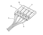
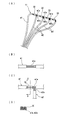
図1は、車両に配索されるワイヤハーネスW/Hの幹線W/H−1から分岐する複数の電線w同士を接続する本実施形態のスプライス部10を示しており、図2(A)に示す樹脂板被覆前のスプライス部11の外面に、真空成形方法で絶縁樹脂板14を被覆することにより、本発明のスプライス部10を形成している。
Hereinafter, embodiments of the present invention will be described with reference to the drawings.
1 to 4 show a first embodiment.
FIG. 1 shows a
樹脂板被覆前のスプライス部11は、ジョイントバスバー12のジョイント部12aから間隔をあけて突設した複数の接続端子部12bに、電線w端末に接続したメス端子13をそれぞれ嵌合接続させた構成としている[図2(B)、(C)]。
The
樹脂板被覆前のスプライス部11を図3に示す真空成形機20にセットし、該スプライス部11の外面に絶縁樹脂板14を被覆する。
真空成形機20は断面凹形状を有し、底板部20aに空気を吸引する吸引管20bを連結している。また、底板部20aには、スプライス部11を載置する載置台21を突設し、載置台21の載置面21aおよび側面21bには前記吸引管20bに繋がる複数の吸気孔21cを設けている。
The
The
真空成形にあたっては、まず、真空成形機20の載置台21にスプライス部11を載置する。スプライス部11は、ワイヤハーネスW/Hの幹線W/H−1の外周面とテープ巻き固定する際に下面側となる面を載置面21aとの接触面としている。
載置台21に載置されたスプライス部11の上面側に、加熱、軟化させた絶縁樹脂板14をセットする[図3(A)]。絶縁樹脂板14として、本実施形態では、厚さ1.5mmのポリプロピレン製の樹脂板14を用い、加熱温度は130℃程度としている。
続いて、吸引管20bおよび載置台21の吸気孔21cから空気を吸引して真空状態にし、絶縁樹脂板14をスプライス部11の外面および載置台21の側面21bに密着させる[図3(B)]。
冷却後、絶縁樹脂板14で被覆されたスプライス部10を載置台21から取り外し、下面側の絶縁樹脂板14の浮きを抑えて形状を整えることにより、図1に示す本発明のスプライス部10を得ることができる。
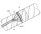
前記スプライス部10を、図4に示すように、ワイヤハーネスW/Hの幹線W/H−1の外周面にテープ巻きすることによりスプライス部10のワイヤハーネスW/Hへの搭載が完了する。
In vacuum forming, first, the
The heated and softened insulating
Subsequently, air is sucked from the
After cooling, the
As shown in FIG. 4, the
前記のように、ジョイントバスバー12の各接続端子部12bと電線w端末の各端子13を嵌合接続してスプライス部11を形成し、真空成形方法でスプライス部11の外面を絶縁樹脂板14で覆う構成としているため、従来のジョイントコネクタのような樹脂成形品からなるハウジングを設けなくても、外面を被覆する絶縁樹脂板14によってスプライス部11をしっかりと絶縁保護することができ、製造コストも低減することができる。
As described above, each
また、絶縁樹脂板14で外面を覆ったスプライス部10は可撓性を有していると共に薄型かつ軽量であるため、スプライス部10をワイヤハーネスW/Hの幹線W/H−1の外周面になめらかに沿わせながらテープ巻き固定することができ、スプライス部10の固定に伴うワイヤハーネスW/Hの大径化や重量化を防止することができる。
In addition, since the
なお、第1実施形態では、真空成形方法により絶縁樹脂板14をスプライス部11の外面に被覆しているが、スプライス部11の上下に加熱、軟化させた絶縁樹脂板14を配置して重ね合わせ、該積層体を上下の金型で挟んで加圧成形することによっても、本発明のスプライス部10を形成することができる。其の際、絶縁樹脂板14としてラミネート材を用いると、スプライス部10を絶縁樹脂板14でラミネートでき、かつ、ラミネート材同士を接着することができる。
In the first embodiment, the insulating
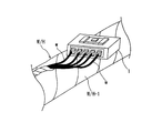
図5は第2実施形態を示している。
第2実施形態では、幹線から分岐された複数の電線wのうち、1本の電線w1の端末側に長さ方向に間隔をあけて中間芯線露出部w1aを設け、他の複数の電線w2の端末芯線露出部w2aを前記各中間芯線露出部w1aに中間圧着端子30で加締接続して、図5(A)に示す樹脂板被覆前のスプライス部11を形成している点以外は第1実施形態と同様としている。
FIG. 5 shows a second embodiment.
In 2nd Embodiment, the intermediate core wire exposure part w1a is provided in the length direction at the terminal side of one electric wire w1 among the some electric wires w branched from the trunk line, and other electric wires w2 Except that the terminal core wire exposed portion w2a is caulked and connected to each intermediate core wire exposed portion w1a by the
前記のように、スプライス部11は、1本の電線w1に設けた複数の中間芯線露出部w1aに、他の複数の電線w2の端末芯線露出部w2aをそれぞれ中間圧着端子30で加締接続するだけのシンプルな構造であるため、絶縁樹脂板14で被覆されたスプライス部10はさらに薄型、軽量となり、該スプライス部10を幹線W/H−1の外周面に固定したワイヤハーネスW/Hの小径化、軽量化も一層容易に実現できる。
As described above, the
10 スプライス部
11 樹脂板被覆前のスプライス部
12 ジョイントバスバー
12a ジョイント部
12b 接続端子部
13 端子
14 絶縁樹脂板
20 真空成形機
20a 底板部
20b 吸引管
21 載置台
21a 載置面
21b 側面
21c 吸気孔
30 中間圧着端子
w、w1、w2 電線
w1a 中間芯線露出部
w2a 端末芯線露出部
DESCRIPTION OF
Claims (4)
前記スプライス部に軟化させた絶縁樹脂板を被せ、
前記絶縁樹脂板を真空成形方法または加圧成形方法で前記スプライス部の外面を覆っていることを特徴とする電線のスプライス部形成方法。 A plurality of connection terminal portions projecting at intervals from the joint portion of the joint bus bar, and a splice portion is provided by fitting and connecting the terminals connected to the plurality of wire terminals,
Cover the splice part with a softened insulating resin plate,
A method for forming a splice portion of an electric wire, wherein the insulating resin plate is covered with an outer surface of the splice portion by a vacuum forming method or a pressure forming method.
前記各中間芯線露出部に前記複数の電線の端末芯線露出部をそれぞれ中間圧着端子で加締接続してスプライス部を設け、
前記スプライス部に軟化させた絶縁樹脂板を被せ、
前記絶縁樹脂板を真空成形方法または加圧成形方法で前記スプライス部の外面を覆っていることを特徴とする電線のスプライス部形成方法。 While providing a plurality of intermediate core wire exposed portions where the insulation coating is peeled and the core wire is exposed at intervals in the length direction on the terminal side of one electric wire, the insulation coating of the other plurality of wire terminals is peeled off to form the core wire The terminal core wire exposed part that exposed
Each of the intermediate core wire exposed portions is provided with a splice portion by crimping and connecting the terminal core wire exposed portions of the plurality of electric wires with intermediate crimp terminals,
Cover the splice part with a softened insulating resin plate,
A method for forming a splice portion of an electric wire, wherein the insulating resin plate is covered with an outer surface of the splice portion by a vacuum forming method or a pressure forming method.
該ワイヤハーネスの幹線から分岐する複数の電線で請求項3に記載のスプライス部が形成されており、該スプライス部を前記幹線の外周面にテープ巻きして搭載していることを特徴とするワイヤハーネス。 A wire harness routed in a vehicle,
The splice portion according to claim 3 is formed by a plurality of electric wires branched from a trunk line of the wire harness, and the splice portion is taped and mounted on the outer peripheral surface of the trunk line. Harness.
Priority Applications (1)
| Application Number | Priority Date | Filing Date | Title |
|---|---|---|---|
| JP2008241570A JP5181967B2 (en) | 2008-09-19 | 2008-09-19 | Wire harness |
Applications Claiming Priority (1)
| Application Number | Priority Date | Filing Date | Title |
|---|---|---|---|
| JP2008241570A JP5181967B2 (en) | 2008-09-19 | 2008-09-19 | Wire harness |
Publications (2)
| Publication Number | Publication Date |
|---|---|
| JP2010073583A true JP2010073583A (en) | 2010-04-02 |
| JP5181967B2 JP5181967B2 (en) | 2013-04-10 |
Family
ID=42205163
Family Applications (1)
| Application Number | Title | Priority Date | Filing Date |
|---|---|---|---|
| JP2008241570A Expired - Fee Related JP5181967B2 (en) | 2008-09-19 | 2008-09-19 | Wire harness |
Country Status (1)
| Country | Link |
|---|---|
| JP (1) | JP5181967B2 (en) |
Cited By (1)
| Publication number | Priority date | Publication date | Assignee | Title |
|---|---|---|---|---|
| JP7371505B2 (en) | 2020-01-20 | 2023-10-31 | 住友電装株式会社 | wire harness |
Citations (4)
| Publication number | Priority date | Publication date | Assignee | Title |
|---|---|---|---|---|
| JPH09102332A (en) * | 1995-07-31 | 1997-04-15 | Yazaki Corp | Joint section for flat circuit body and manufacture thereof |
| JPH09137881A (en) * | 1995-11-15 | 1997-05-27 | Sumitomo Wiring Syst Ltd | Clamp provided with insulation cap for splice part |
| JPH1126036A (en) * | 1997-07-01 | 1999-01-29 | Sumitomo Wiring Syst Ltd | Protecting structure for electric wire end joint part of wire harness |
| JP2005166506A (en) * | 2003-12-03 | 2005-06-23 | Sumitomo Wiring Syst Ltd | Protection material of terminal concentration splicing part |
-
2008
- 2008-09-19 JP JP2008241570A patent/JP5181967B2/en not_active Expired - Fee Related
Patent Citations (4)
| Publication number | Priority date | Publication date | Assignee | Title |
|---|---|---|---|---|
| JPH09102332A (en) * | 1995-07-31 | 1997-04-15 | Yazaki Corp | Joint section for flat circuit body and manufacture thereof |
| JPH09137881A (en) * | 1995-11-15 | 1997-05-27 | Sumitomo Wiring Syst Ltd | Clamp provided with insulation cap for splice part |
| JPH1126036A (en) * | 1997-07-01 | 1999-01-29 | Sumitomo Wiring Syst Ltd | Protecting structure for electric wire end joint part of wire harness |
| JP2005166506A (en) * | 2003-12-03 | 2005-06-23 | Sumitomo Wiring Syst Ltd | Protection material of terminal concentration splicing part |
Cited By (1)
| Publication number | Priority date | Publication date | Assignee | Title |
|---|---|---|---|---|
| JP7371505B2 (en) | 2020-01-20 | 2023-10-31 | 住友電装株式会社 | wire harness |
Also Published As
| Publication number | Publication date |
|---|---|
| JP5181967B2 (en) | 2013-04-10 |
Similar Documents
| Publication | Publication Date | Title |
|---|---|---|
| JP5672158B2 (en) | Connector manufacturing method | |
| WO2014007297A1 (en) | Connector terminal with sheathed wire attached, and water-stopping method for connector terminal with sheathed wire attached | |
| JP5792011B2 (en) | Flat cable waterproof connector structure and connection method thereof | |
| JP5181967B2 (en) | Wire harness | |
| CN105489288A (en) | Flat cable and method for manufacturing the same | |
| WO2018012236A1 (en) | Connector and electrical connection assembly provided therewith | |
| WO2015056561A1 (en) | Wire harness and protective member | |
| JP5954165B2 (en) | Wire harness | |
| WO2012114732A1 (en) | Method for forming short circuit in wire harness | |
| JP2008270108A (en) | Coaxial flat cable, and manufacturing method thereof | |
| JP5609685B2 (en) | Method for manufacturing shield body provided in wire harness | |
| JP4103327B2 (en) | Wire harness protection structure | |
| JP5110003B2 (en) | Coaxial flat cable manufacturing method | |
| JP2001319714A (en) | Terminal treatment method of flat type electric wire | |
| JP2005078811A (en) | Electrode part structure of flexible flat cable, flexible flat cable, and its manufacturing method | |
| JP2001128343A (en) | Structure and method for wire harness attachment | |
| JPH10261444A (en) | Coating layer formation method and coating structure of wire branched part | |
| JPH10188682A (en) | Wire harness and its manufacture | |
| JP4568220B2 (en) | Crimping device and flat circuit body unit | |
| JPH0562540A (en) | Manufacture of flat wire harness | |
| JP2014154280A (en) | Flat wiring material and method for producing the same | |
| JPH06349340A (en) | Structure for automobile wire harness | |
| JP4918917B2 (en) | Flat cable manufacturing method | |
| JPH06181009A (en) | Cable core and multiple core cable | |
| JP2003197042A (en) | Shielded wire harness structure and manufacturing method of shielded wire harness |
Legal Events
| Date | Code | Title | Description |
|---|---|---|---|
| A621 | Written request for application examination |
Free format text: JAPANESE INTERMEDIATE CODE: A621 Effective date: 20110330 |
|
| A977 | Report on retrieval |
Free format text: JAPANESE INTERMEDIATE CODE: A971007 Effective date: 20120831 |
|
| A131 | Notification of reasons for refusal |
Free format text: JAPANESE INTERMEDIATE CODE: A131 Effective date: 20120911 |
|
| A521 | Written amendment |
Free format text: JAPANESE INTERMEDIATE CODE: A523 Effective date: 20121112 |
|
| TRDD | Decision of grant or rejection written | ||
| A01 | Written decision to grant a patent or to grant a registration (utility model) |
Free format text: JAPANESE INTERMEDIATE CODE: A01 Effective date: 20121218 |
|
| A61 | First payment of annual fees (during grant procedure) |
Free format text: JAPANESE INTERMEDIATE CODE: A61 Effective date: 20121231 |
|
| R150 | Certificate of patent or registration of utility model |
Free format text: JAPANESE INTERMEDIATE CODE: R150 |
|
| FPAY | Renewal fee payment (event date is renewal date of database) |
Free format text: PAYMENT UNTIL: 20160125 Year of fee payment: 3 |
|
| LAPS | Cancellation because of no payment of annual fees |