JP2010073501A - 調光信号変換回路 - Google Patents
調光信号変換回路 Download PDFInfo
- Publication number
- JP2010073501A JP2010073501A JP2008240038A JP2008240038A JP2010073501A JP 2010073501 A JP2010073501 A JP 2010073501A JP 2008240038 A JP2008240038 A JP 2008240038A JP 2008240038 A JP2008240038 A JP 2008240038A JP 2010073501 A JP2010073501 A JP 2010073501A
- Authority
- JP
- Japan
- Prior art keywords
- dimming signal
- width modulation
- conversion circuit
- pulse width
- discharge lamp
- Prior art date
- Legal status (The legal status is an assumption and is not a legal conclusion. Google has not performed a legal analysis and makes no representation as to the accuracy of the status listed.)
- Granted
Links
- 238000006243 chemical reaction Methods 0.000 title claims abstract description 51
- 239000003990 capacitor Substances 0.000 description 4
- 239000004973 liquid crystal related substance Substances 0.000 description 4
- 238000000034 method Methods 0.000 description 3
- 238000010586 diagram Methods 0.000 description 2
- 239000000758 substrate Substances 0.000 description 2
- 230000005540 biological transmission Effects 0.000 description 1
- 230000003287 optical effect Effects 0.000 description 1
Images

Landscapes
- Circuit Arrangements For Discharge Lamps (AREA)
- Discharge-Lamp Control Circuits And Pulse- Feed Circuits (AREA)
Abstract
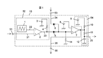
【解決手段】 調光信号変換回路13は、直流電圧調光信号を入力するための直流電圧調光信号入力部51と、直流電圧調光信号入力部51から入力された直流電圧調光信号をパルス幅変調信号に変換する第1の変換回路52と、外部からパルス幅変調調光信号を入力するためのパルス幅変調調光信号入力部53と、第1の変換回路52またはパルス幅変調調光信号入力部53から入力されたパルス幅変調信号を直流電圧調光信号に変換する第2の変換回路54と、第2の変換回路54に入力されるパルス幅変調信号を外部に出力するためのパルス幅変調調光信号出力部55とを備える。
【選択図】 図1
Description
2 比較器
3、8、9 基準電源
4、10 プルアップ抵抗
5、6 ダイオード
7 比較器
11 時定数設定抵抗
12 時定数設定コンデンサ
13 調光信号変換回路
14 プルダウン抵抗
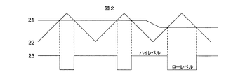
21、25 直流電圧調光信号
22 三角波
23、24、26 パルス幅変調信号
51 直流電圧調光信号入力部
52 第1の変換回路
53 パルス幅変調調光信号入力部
54 第2の変換回路
55 パルス幅変調調光信号出力部
Claims (3)
- 直流電圧調光信号を入力するための直流電圧調光信号入力部と、前記直流電圧調光信号入力部から入力された直流電圧調光信号をパルス幅変調信号に変換する第1の変換回路と、外部からパルス幅変調調光信号を入力するためのパルス幅変調調光信号入力部と、前記第1の変換回路または前記パルス幅変調調光信号入力部から入力されたパルス幅変調信号を直流電圧調光信号に変換する第2の変換回路と、前記第2の変換回路に入力されるパルス幅変調信号を外部に出力するためのパルス幅変調調光信号出力部とを備えたことを特徴とする調光信号変換回路。
- 請求項1記載の調光信号変換回路と、前記調光信号変換回路から入力された直流電圧調光信号に基づいて放電灯を点灯する放電灯点灯回路とを備えたことを特徴とする放電灯点灯装置。
- 請求項2記載の放電灯点灯装置を複数備え、前記放電灯点灯装置の調光信号変換回路のパルス幅変調調光信号出力部が隣接する他の放電灯点灯装置の調光信号変換回路のパルス幅変調調光信号入力部に接続されることを特徴とする放電灯点灯装置。
Priority Applications (1)
| Application Number | Priority Date | Filing Date | Title |
|---|---|---|---|
| JP2008240038A JP5144445B2 (ja) | 2008-09-18 | 2008-09-18 | 調光信号変換回路 |
Applications Claiming Priority (1)
| Application Number | Priority Date | Filing Date | Title |
|---|---|---|---|
| JP2008240038A JP5144445B2 (ja) | 2008-09-18 | 2008-09-18 | 調光信号変換回路 |
Publications (2)
| Publication Number | Publication Date |
|---|---|
| JP2010073501A true JP2010073501A (ja) | 2010-04-02 |
| JP5144445B2 JP5144445B2 (ja) | 2013-02-13 |
Family
ID=42205093
Family Applications (1)
| Application Number | Title | Priority Date | Filing Date |
|---|---|---|---|
| JP2008240038A Expired - Fee Related JP5144445B2 (ja) | 2008-09-18 | 2008-09-18 | 調光信号変換回路 |
Country Status (1)
| Country | Link |
|---|---|
| JP (1) | JP5144445B2 (ja) |
-
2008
- 2008-09-18 JP JP2008240038A patent/JP5144445B2/ja not_active Expired - Fee Related
Also Published As
| Publication number | Publication date |
|---|---|
| JP5144445B2 (ja) | 2013-02-13 |
Similar Documents
| Publication | Publication Date | Title |
|---|---|---|
| CN104735843B (zh) | 自动切换调光模式的发光二极管控制器 | |
| US20170006679A1 (en) | Signal generating method and circuit for controlling dimming of led | |
| KR101046124B1 (ko) | Led 구동 회로 | |
| US20110156604A1 (en) | Driving circuit of light emitting diode | |
| JP2010021008A (ja) | Led照明装置 | |
| JP6108143B2 (ja) | 過電流防止式電源装置及びそれを用いた照明器具 | |
| US9380668B2 (en) | PDM modulation of LED current | |
| JP5719260B2 (ja) | 照明装置 | |
| JP5083189B2 (ja) | 照明光通信装置、及び照明光通信システム | |
| CN101345025B (zh) | 背光调节电路与背光调节方法 | |
| JP5144445B2 (ja) | 調光信号変換回路 | |
| WO2018192470A1 (zh) | 多功能led调光接口电路 | |
| JP5139956B2 (ja) | Led照明装置 | |
| US9179515B2 (en) | Driver circuit for LED backlight of liquid crystal display device | |
| KR100674256B1 (ko) | 디밍 제어 방법 및 이를 이용하는 조명 시스템 | |
| CN102612201B (zh) | 发光二极管驱动电路及其系统 | |
| KR101978509B1 (ko) | Led 구동장치 | |
| KR100785161B1 (ko) | 멀티램프모듈 구동시스템 | |
| TWI697255B (zh) | 可接收脈波寬度調變信號與直流信號的調光控制器與相關之調光方法 | |
| CN102903339A (zh) | 显示装置背光源的控制方法及控制装置 | |
| KR101185157B1 (ko) | 형광등 디밍 안정기의 출력을 이용한 엘이디 디밍 제어회로 | |
| US20140333227A1 (en) | Light Source Module, Light Source Module Driving Circuit and Driving Method | |
| Lin et al. | Development and implementation of a laser headlight system for electro‐optic characteristic measurement and comparison | |
| KR100526240B1 (ko) | 복합디밍제어방식의 냉음극형광램프용 인버터 | |
| CN105551441B (zh) | 一种区域背光调整装置及其调整方法 |
Legal Events
| Date | Code | Title | Description |
|---|---|---|---|
| A711 | Notification of change in applicant |
Free format text: JAPANESE INTERMEDIATE CODE: A712 Effective date: 20101217 |
|
| A621 | Written request for application examination |
Free format text: JAPANESE INTERMEDIATE CODE: A621 Effective date: 20110816 |
|
| A977 | Report on retrieval |
Free format text: JAPANESE INTERMEDIATE CODE: A971007 Effective date: 20120914 |
|
| TRDD | Decision of grant or rejection written | ||
| A01 | Written decision to grant a patent or to grant a registration (utility model) |
Free format text: JAPANESE INTERMEDIATE CODE: A01 Effective date: 20121030 |
|
| A01 | Written decision to grant a patent or to grant a registration (utility model) |
Free format text: JAPANESE INTERMEDIATE CODE: A01 |
|
| A61 | First payment of annual fees (during grant procedure) |
Free format text: JAPANESE INTERMEDIATE CODE: A61 Effective date: 20121122 |
|
| FPAY | Renewal fee payment (event date is renewal date of database) |
Free format text: PAYMENT UNTIL: 20151130 Year of fee payment: 3 |
|
| R150 | Certificate of patent or registration of utility model |
Free format text: JAPANESE INTERMEDIATE CODE: R150 |
|
| LAPS | Cancellation because of no payment of annual fees |