JP2010072634A - Optical scanning apparatus, image forming apparatus, control method, program and recording medium - Google Patents
Optical scanning apparatus, image forming apparatus, control method, program and recording medium Download PDFInfo
- Publication number
- JP2010072634A JP2010072634A JP2009181168A JP2009181168A JP2010072634A JP 2010072634 A JP2010072634 A JP 2010072634A JP 2009181168 A JP2009181168 A JP 2009181168A JP 2009181168 A JP2009181168 A JP 2009181168A JP 2010072634 A JP2010072634 A JP 2010072634A
- Authority
- JP
- Japan
- Prior art keywords
- optical scanning
- interval
- scanning device
- value
- scanned
- Prior art date
- Legal status (The legal status is an assumption and is not a legal conclusion. Google has not performed a legal analysis and makes no representation as to the accuracy of the status listed.)
- Granted
Links
Images


Classifications
-
- B—PERFORMING OPERATIONS; TRANSPORTING
- B41—PRINTING; LINING MACHINES; TYPEWRITERS; STAMPS
- B41J—TYPEWRITERS; SELECTIVE PRINTING MECHANISMS, i.e. MECHANISMS PRINTING OTHERWISE THAN FROM A FORME; CORRECTION OF TYPOGRAPHICAL ERRORS
- B41J2/00—Typewriters or selective printing mechanisms characterised by the printing or marking process for which they are designed
- B41J2/435—Typewriters or selective printing mechanisms characterised by the printing or marking process for which they are designed characterised by selective application of radiation to a printing material or impression-transfer material
- B41J2/47—Typewriters or selective printing mechanisms characterised by the printing or marking process for which they are designed characterised by selective application of radiation to a printing material or impression-transfer material using the combination of scanning and modulation of light
- B41J2/471—Typewriters or selective printing mechanisms characterised by the printing or marking process for which they are designed characterised by selective application of radiation to a printing material or impression-transfer material using the combination of scanning and modulation of light using dot sequential main scanning by means of a light deflector, e.g. a rotating polygonal mirror
- B41J2/473—Typewriters or selective printing mechanisms characterised by the printing or marking process for which they are designed characterised by selective application of radiation to a printing material or impression-transfer material using the combination of scanning and modulation of light using dot sequential main scanning by means of a light deflector, e.g. a rotating polygonal mirror using multiple light beams, wavelengths or colours
Abstract
Description
本発明は、共通の光源からのビームにより相異なる被走査面を走査する光走査装置、その光走査装置を備える画像形成装置に関し、また、共通の光源からのビームにより相異なる被走査面を所定のタイミングで走査するための制御方法、その方法を実現するためのコンピュータ可読なプログラム、そのプログラムが記録された記録媒体に関する。 The present invention relates to an optical scanning device that scans different scanned surfaces with a beam from a common light source, an image forming apparatus including the optical scanning device, and a predetermined scanned surface with a beam from a common light source. And a computer-readable program for realizing the method, and a recording medium on which the program is recorded.
レーザプリンタ、ファックス装置、デジタル複合機等で用いられる電子写真画像形成装置では、印刷等のカラー化や高速化により、感光体ドラムを複数備えるタンデム方式の装置が普及してきている。このタンデム方式の装置では、複数の感光体ドラムのそれぞれに対し、光を照射する必要があるため、感光体ドラムの数が増加するに伴い、光源数が増加する。この光源数の増加は、部品点数の増加をもたらし、コストアップを生じ、さらには複数光源間の波長差に起因する色ずれをもたらす。また、光源数が増加すると、半導体レーザの劣化による書き込みユニットの故障確率も増加し、リサイクル性が低下する。 In electrophotographic image forming apparatuses used in laser printers, fax machines, digital multi-function peripherals, etc., tandem type apparatuses having a plurality of photosensitive drums have become widespread due to colorization and high speed printing. In this tandem apparatus, since it is necessary to irradiate each of the plurality of photosensitive drums, the number of light sources increases as the number of photosensitive drums increases. This increase in the number of light sources causes an increase in the number of parts, resulting in an increase in cost, and further a color shift due to a wavelength difference between a plurality of light sources. Further, when the number of light sources increases, the failure probability of the writing unit due to deterioration of the semiconductor laser also increases, and the recyclability decreases.
そこで、タンデム方式の電子写真画像形成装置において、光源数を増加させないようにするために、共通の光源からのビームを分割し、分割された各ビームにより相異なる被走査面を走査する装置が提案されている(特許文献1参照)。この装置は、光源の出射光束を光束分割手段で2本に分け、互いに角度をずらして重ねた2枚のポリゴンミラーを同軸で回転させる偏向手段の上下段に取り付けられたポリゴンミラーにそれぞれ入力させ、この偏向手段により相異なるタイミングで偏向走査された各光束を、それぞれ所定の光学系である第1走査レンズ、ミラー、第2走査レンズを経て別個の感光体に到り主走査を行うように構成されている。 Therefore, in order to prevent an increase in the number of light sources in a tandem electrophotographic image forming apparatus, an apparatus that divides a beam from a common light source and scans different surfaces to be scanned by the divided beams is proposed. (See Patent Document 1). In this apparatus, the light beam emitted from the light source is split into two by the light beam splitting means, and the two polygon mirrors that are overlapped at different angles are input to the polygon mirrors mounted on the upper and lower stages of the deflecting means for coaxial rotation. Each light beam deflected and scanned by this deflecting means at different timings reaches a separate photoconductor through a first scanning lens, a mirror, and a second scanning lens, which are predetermined optical systems, and performs main scanning. It is configured.
このように複数段のポリゴンミラーにて相異なる被走査面を走査するための光学的配置を規定することで、光源数を減らしながらも、高速な画像出力を可能にするとともに、ゴースト光を発生させず、良好な画像出力を可能にするものである。光源数の減少は、部品点数を減少させ、低コスト化を実現し、ユニット全体の故障率を減少させ、リサイクル性を向上させることができる。 In this way, by defining the optical arrangement for scanning different scanning surfaces with multiple stages of polygon mirrors, while reducing the number of light sources, high-speed image output is possible and ghost light is generated This makes it possible to output a good image. The reduction in the number of light sources can reduce the number of parts, achieve cost reduction, reduce the failure rate of the entire unit, and improve the recyclability.
なお、この装置では、相異なる段のポリゴンミラーの回転方向の角度ずれ量φ、ポリゴンミラーのミラー面の面数Mから、相異なる段の多面の反射鏡の回転方向のずれ角φがπ/Mになることを特徴としている。すなわち、4面のポリゴンミラーを使用した場合、ずれ角φはπ/4(45deg)とされる。 In this apparatus, the angular deviation amount φ in the rotational direction of the polygon mirrors at different stages and the number M of the mirror surfaces of the polygon mirror are calculated so that the deviation angle φ in the rotational direction of the multi-surface reflective mirrors at different stages is π / It is characterized by becoming M. That is, when a four-sided polygon mirror is used, the shift angle φ is π / 4 (45 deg).
上記従来の装置では、共通の光源からのビームを分割し、分割された各ビームにより相異なる被走査面を走査するには、ポリゴンミラーによる走査タイミングと光源の点灯タイミングとを合わせなければならない。つまり、その装置では、ポリゴンミラーを被走査面に合わせて多段のポリゴンミラーのミラー面の位相(回転方向への角度)をずらして製作されているので、光源を点灯させるデータは、ポリゴンミラーの回転位相と被走査面のデータと合ったものでなければならない。 In the conventional apparatus described above, in order to divide a beam from a common light source and scan different surfaces to be scanned by the divided beams, the scanning timing by the polygon mirror and the lighting timing of the light source must be matched. That is, in the apparatus, the polygon mirror is aligned with the surface to be scanned and the mirror surface of the multi-stage polygon mirror is shifted in phase (angle in the rotation direction). The rotation phase must match the data of the scanned surface.
ポリゴンミラーの回転位相の検出には、画像領域外に配置した受光素子により、ミラー面が所定の位相に到達したタイミングをビーム入射光にて検出する技術が広く知られている。この技術により検出する場合、複数段のポリゴンミラーの回転角を検出することは可能であるが、相異なる段のポリゴンミラーの回転方向の角度ずれ量が均一であるので、各段のポリゴンミラーの回転位相を検出することは不可能である。つまり、ポリゴンミラーを2段に重ねた構成では、この2段に重ねられたポリゴンミラーが所定の回転角に到達したことは検出可能であるが、上段と下段のどちらが所定の回転角に到達しているかを検出することは不可能である。 For detecting the rotational phase of the polygon mirror, a technique is widely known in which a light receiving element arranged outside the image region detects the timing at which the mirror surface reaches a predetermined phase with beam incident light. When detecting with this technique, it is possible to detect the rotation angles of the polygon mirrors in a plurality of stages. However, since the amount of angular deviation in the rotation direction of the polygon mirrors in different stages is uniform, It is impossible to detect the rotational phase. That is, in the configuration in which the polygon mirrors are stacked in two stages, it can be detected that the polygon mirrors stacked in the two stages have reached the predetermined rotation angle, but either the upper stage or the lower stage has reached the predetermined rotation angle. It is impossible to detect whether
一般的なカラー画像を形成する画像形成装置では、4つの感光体ドラムに静電潜像を形成し、マゼンタ、イエロー、シアン、ブラックのトナーにより個別にトナー像を形成する。このことから、4つの感光体ドラムと4つの被走査面は対応している。すなわち、マゼンタとイエローを上段と下段で走査する構成では、マゼンタと上段のポリゴンミラー、イエローと下段のポリゴンミラーが対応している。感光体ドラムとポリゴンミラーの対応を取り違えてしまった場合、マゼンタの感光体ドラムでイエローの静電潜像を形成し、イエローの感光体ドラムでマゼンタの静電潜像を形成することとなり、最終出力である転写紙上のカラー画像出力が適切な配色にならないという問題があった。 In an image forming apparatus that forms a general color image, electrostatic latent images are formed on four photosensitive drums, and toner images are individually formed with magenta, yellow, cyan, and black toners. For this reason, the four photosensitive drums correspond to the four scanned surfaces. That is, in the configuration in which magenta and yellow are scanned in the upper and lower stages, magenta and upper polygon mirrors, and yellow and lower polygon mirrors correspond to each other. If the correspondence between the photosensitive drum and the polygon mirror is mistaken, a yellow electrostatic latent image is formed on the magenta photosensitive drum, and a magenta electrostatic latent image is formed on the yellow photosensitive drum. There is a problem that the color image output on the transfer paper as an output does not have an appropriate color scheme.
そこで、どの段のポリゴンミラーがどのタイミングで走査するかを検出することができる装置および方法の提供が望まれていた。 Therefore, it has been desired to provide an apparatus and a method capable of detecting which stage of polygon mirror scans at which timing.
本発明は、上記課題を解決するために、複数段の多面反射鏡であるポリゴンミラーにより走査されたビームを検知する受光手段と、その受光手段が検知したビームの検知間隔から、各段の多面反射鏡により走査を行うタイミングを検出する検出手段とを備え、ポリゴンミラーのずれ角を不均等にした構成とする。これにより、どの段の多面反射鏡がどのタイミングで走査するかを検知することができ、被走査面に適切な色の静電潜像を形成することが可能となる。 In order to solve the above-mentioned problems, the present invention provides a light receiving means for detecting a beam scanned by a polygon mirror, which is a multi-stage multi-faced reflecting mirror, and a multi-sided surface of each stage from the detection interval of the beam detected by the light receiving means And a detecting means for detecting the timing of scanning with the reflecting mirror, and the misalignment angle of the polygon mirror is made uneven. Thereby, it is possible to detect which stage of the multi-surface reflecting mirror scans at which timing, and it is possible to form an electrostatic latent image of an appropriate color on the surface to be scanned.
また、光源数を減らしながらも、高速な画像出力を可能にし、新たな部品追加を行うことなく、各ミラー面の走査角度を検出することができる。光源数の減少に伴い、部品点数を減らし、低コスト化を実現することができ、光走査装置のユニット全体の故障率を減少させ、リサイクル性を向上させることもできる。 In addition, while reducing the number of light sources, high-speed image output is possible, and the scanning angle of each mirror surface can be detected without adding new components. As the number of light sources is reduced, the number of parts can be reduced and the cost can be reduced, the failure rate of the entire unit of the optical scanning device can be reduced, and the recyclability can be improved.
上記受光手段と検出手段を備える構成では、多面反射鏡の回転状態が安定し、正常に動作している場合には問題ないが、ずれ角が小さいことから、回転状態がわずかでも不安定になると、正確に検知することができなくなる。このため、多面反射鏡の回転状態が安定し、正常に動作しているかを、検出手段による検出結果から判定する判定手段をさらに備えることが望ましい。 In the configuration including the light receiving means and the detection means, there is no problem when the rotating state of the multi-surface reflecting mirror is stable and operating normally, but since the deviation angle is small, the rotating state becomes slightly unstable. It becomes impossible to detect accurately. For this reason, it is desirable to further include a determination unit that determines from the detection result by the detection unit whether the rotational state of the polygonal reflecting mirror is stable and operating normally.
このように多面反射鏡の回転状態が適切であるかを判定することで、適切なカラー画像出力を実現することができる。また、光走査装置の構成部品の不具合を検出することも可能となる。 Thus, by determining whether the rotation state of the multi-surface reflecting mirror is appropriate, it is possible to realize an appropriate color image output. It is also possible to detect a defect in the components of the optical scanning device.
したがって、本発明によれば、回転軸と前記回転軸に少なくとも2段に、かつ回転方向へ角度をずらして周設された多面反射鏡とを有する偏向手段と、光源からのビームを少なくとも2つに分割し、分割された各ビームを相異なる段の多面反射鏡へ入射させる分割手段とを備え、回転軸を中心として回転する相異なる段の多面反射鏡により反射された各ビームが相異なる被走査面を走査する光走査装置であって、偏向手段により走査されるビームを検知する受光手段と、受光手段によるビームの検知間隔に基づき、各段の多面反射鏡により走査を行うタイミングを検出する検出手段とをさらに備える、光走査装置が提供される。また、この光走査装置は、検出手段による検出結果に基づき、多面反射鏡が正常に回転しているか否かを判定する判定手段とをさらに備えることができる。 Therefore, according to the present invention, at least two beams from the light source and the deflecting means having the rotating shaft and the multi-faced reflecting mirror provided around the rotating shaft in at least two stages and shifted in the rotational direction are arranged. And splitting means for causing the divided beams to enter the multi-stage reflecting mirrors of different stages, and the beams reflected by the multi-stage reflecting mirrors of different stages rotating about the rotation axis are differently covered. An optical scanning device that scans a scanning surface, and detects a timing at which scanning is performed by a multi-surface reflecting mirror at each stage based on a light receiving unit that detects a beam scanned by a deflecting unit and a beam detection interval by the light receiving unit. An optical scanning device is further provided, further comprising detection means. In addition, the optical scanning device can further include a determination unit that determines whether or not the polyhedral reflecting mirror is normally rotated based on a detection result by the detection unit.
光源は、複数の発光部を有する面発光型半導体レーザアレイ素子が好ましい。光走査装置の部品点数を減少させることができるからである。 The light source is preferably a surface emitting semiconductor laser array element having a plurality of light emitting portions. This is because the number of parts of the optical scanning device can be reduced.
偏光手段が、4つの反射面をもつ多面反射鏡であり、上段の多面反射鏡に対し、下段の多面反射鏡が回転方向へ45°程角度をずらして回転軸に配設されたものである場合、検知信号の間隔は等間隔となり、一定間隔で各段の多面反射鏡による走査が開始され、どの段の多面反射鏡がどのタイミングで走査しているかを検出するのは困難である。これに対し、偏光手段が、4つの反射面をもつ多面反射鏡であり、上段の多面反射鏡に対し、下段の多面反射鏡が回転方向へ45°±α程角度をずらして回転軸に配設されたものである場合、わずかなずれ量であっても検知信号の間隔が異なるものとなり、どの段の多面反射鏡がどのタイミングで走査しているかを検出することが可能となる。そこで、偏向手段は、受光手段によるビームの検知間隔が等間隔にならないように各段の多面反射鏡が回転方向へ角度をずらして配設されていることを特徴とする。 The polarizing means is a multi-surface reflecting mirror having four reflecting surfaces, and the lower multi-surface reflecting mirror is disposed on the rotation axis at an angle of 45 ° in the rotational direction with respect to the upper multi-surface reflecting mirror. In this case, the intervals of the detection signals are equal, and scanning by the polyhedral reflectors at each stage is started at a constant interval, and it is difficult to detect which stage of the polyhedral reflector is scanned at which timing. On the other hand, the polarizing means is a multi-surface reflecting mirror having four reflecting surfaces, and the lower multi-surface reflecting mirror is shifted from the upper multi-surface reflecting mirror by 45 ° ± α in the rotation direction and arranged on the rotation axis. In the case of being provided, the intervals of the detection signals are different even with a slight amount of deviation, and it is possible to detect which stage of the multi-surface reflecting mirror is scanning at which timing. Therefore, the deflecting means is characterized in that the multi-surface reflecting mirrors of each stage are arranged at different angles in the rotation direction so that the detection intervals of the beams by the light receiving means are not equal.
上記角度は、π/M±α(Mは多面反射鏡の面数、αは角度ずれ量)で表され、αは、多面反射鏡の組み立て時の許容範囲である公差の絶対値より大きいことを特徴とする。公差とは、規定値と実物の値との差で、法令で許容される範囲で、機械加工でいう許し代である。αがその公差の絶対値と同じである場合、実際の検出時に、検知信号の間隔が等間隔となり、どの段の多面反射鏡がどのタイミングで走査しているかを検出することはできない。しかしながら、公差の絶対値より大きくすることで、上記のように、検知信号の間隔が異なるものとなり、どの段の多面反射鏡がどのタイミングで走査しているかを検出することができる。 The angle is represented by π / M ± α (M is the number of faces of the multi-faced reflector, and α is the amount of angular deviation), and α is larger than the absolute value of the tolerance that is an allowable range when the multi-faced reflector is assembled. It is characterized by. Tolerance is the difference between the specified value and the actual value, and is the allowance in machining within the range allowed by law. When α is the same as the absolute value of the tolerance, at the actual detection, the intervals of the detection signals are equal, and it is impossible to detect which stage of the polygonal mirror is scanned at which timing. However, by making it larger than the absolute value of the tolerance, the intervals of the detection signals are different as described above, and it is possible to detect which stage of the polygonal mirror is scanned at which timing.
検出手段は、受光手段から出力された検知信号の間隔を計測する計測手段を含むことができる。また、検出手段は、計測手段により計測された間隔を、それ以前に計測された計測値または予め設定された固定値と比較し、その間隔が計測値または固定値より大きいか否かを判定する比較判定手段をさらに含むことができる。計測値としては、直前に計測した間隔を採用することができる。固定値としては、一例として、事前に検知信号の間隔を計測し、計測したすべての間隔の平均値を採用することができる。 The detection means can include a measurement means for measuring an interval between detection signals output from the light receiving means. Further, the detecting means compares the interval measured by the measuring means with a previously measured value or a preset fixed value, and determines whether or not the interval is larger than the measured value or the fixed value. A comparison / determination unit may be further included. As the measurement value, the interval measured immediately before can be used. As an example of the fixed value, an interval between detection signals can be measured in advance, and an average value of all measured intervals can be employed.
判定手段は、比較判定手段が判定した比較結果から、上記計測値または固定値より大きい間隔と、上記計測値または固定値より小さい間隔とが交互に検出される場合に正常に動作していると判定し、それ以外の場合には正常に動作していないと判定する。 The determination means is operating normally when an interval larger than the measured value or fixed value and an interval smaller than the measured value or fixed value are alternately detected from the comparison result determined by the comparison determining means. Otherwise, it is determined that it is not operating normally.
この光走査装置は、検出された各段の多面反射鏡により走査を行うタイミングに基づき、光源を点灯させるデータを、走査を行わせるべき段の多面反射鏡に対応させて選択するデータ選択手段をさらに備えることができる。これにより、所定の被走査面に所定の色の静電潜像を確実に形成することができる。 The optical scanning device includes data selection means for selecting data for turning on the light source in correspondence with the multi-surface reflecting mirror of the stage to be scanned based on the detected timing of scanning by the multi-surface reflecting mirror of each stage. Furthermore, it can be provided. Thereby, an electrostatic latent image of a predetermined color can be reliably formed on a predetermined surface to be scanned.
本発明では、上記の光走査装置と、各々が光走査装置により走査される被走査面を有する複数の像担持体とを備える画像形成装置も提供することができる。 The present invention can also provide an image forming apparatus including the above optical scanning device and a plurality of image carriers each having a scanned surface that is scanned by the optical scanning device.
また、本発明では、回転軸を中心として回転する異なる段の多面反射鏡により反射された各ビームが異なる被走査面を所定のタイミングで走査するために実行される制御方法も提供することができる。この方法は、偏向手段により走査されるビームを検知するステップと、受光手段によるビームの検知間隔に基づき、各段の多面反射鏡により走査を行うタイミングを検出するステップとを含む。また、この方法は、検出するステップで検出された検出結果に基づき、多面反射鏡が正常に回転しているか否かを判定するステップとをさらに含むことができる。さらに、この方法は、上記の計測手段、比較判定手段、データ選択手段により行われる処理ステップを含む。 In addition, the present invention can also provide a control method that is executed in order that each beam reflected by the multi-stage reflecting mirrors of different stages rotating around the rotation axis scans different surfaces to be scanned at a predetermined timing. . This method includes a step of detecting a beam scanned by the deflecting unit, and a step of detecting a timing at which scanning is performed by a multi-surface reflecting mirror at each stage based on a beam detection interval by the light receiving unit. The method may further include a step of determining whether or not the polyhedral reflecting mirror is normally rotated based on the detection result detected in the detecting step. Further, this method includes processing steps performed by the measurement unit, the comparison determination unit, and the data selection unit.
本発明では、上記の制御方法を実現するためのコンピュータ可読なプログラムや、そのプログラムが記録された記録媒体も提供することができる。 In the present invention, a computer-readable program for realizing the above control method and a recording medium on which the program is recorded can also be provided.
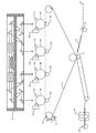
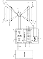
図1は、本実施形態におけるタンデム方式のカラー画像形成装置の構成を示した図である。このカラー画像形成装置は、4つの感光体ドラム10a〜10dと、4つの帯電ユニット11a〜11dと、現像ユニットとしての4つのトナーカートリッジ12a〜12dと、4つの転写ローラ13a〜13dと、感光体ドラム10a〜10d上のトナーを除去する図示しない4つのクリーナーと、中間転写ベルト14と、中間転写ローラ15と、中間転写ベルトクリーニング装置16と、転写装置17と、給紙レジストセンサ18と、定着装置19と、排紙装置20と、光走査装置21とから構成されている。
FIG. 1 is a diagram illustrating the configuration of a tandem color image forming apparatus according to the present embodiment. This color image forming apparatus includes four
光走査装置21は、カラー画像形成装置の開始ボタンが押下されると、あるいはプリンタホストからの印刷ジョブ開始信号が有効にされると、タイミング制御したビームを感光体ドラム10a〜10d上に露光する。この光走査装置21では、ポリゴンモータにより上下2段の多面反射鏡であるポリゴンミラーを回転させ、光源からのビームを走査させ、感光体ドラム10a〜10dの被走査面にそれぞれビームを書き込み、静電潜像を形成する。
When the start button of the color image forming apparatus is pressed or the print job start signal from the printer host is validated, the
その形成された静電潜像は、トナーカートリッジ12a〜12dから供給されるトナーにより現像され、各感光体ドラム10a〜10d上では単色画像が形成される。図1に示す実施形態では、まず、最初の感光体ドラム10aではブラック(K)のトナーが付着され、黒画像が形成されて、転写ローラ13aにより中間転写ベルト14上に転写される。次の感光体ドラム10bではシアン(C)のトナーが付着され、シアン画像が形成されて、転写ローラ13bにより中間転写ベルト14上に転写される。なお、この中間転写ベルト14上には既に黒画像が転写されているため、その上にシアン画像が転写される。
The formed electrostatic latent images are developed with the toner supplied from the
さらに次の感光体ドラム10cではイエロー(Y)のトナーが付着され、黄画像が形成されて、転写ローラ13cにより中間転写ベルト14上に転写される。この中間転写ベルト14上には既に黒画像およびシアン画像が転写されているため、それらの上に黄画像が転写される。最後の感光体ドラム10dではマゼンタ(M)のトナーが付着され、転写ローラ13dにより中間転写ベルト14上に転写される。中間転写ベルト14上には既に黒画像およびシアン画像および黄画像上にマゼンタ画像が転写される。なお、中間転写ベルト14は、中間転写ローラ15を駆動ローラとして回転駆動することにより転写された各色のトナー像を所定方向へ搬送する。このように中間転写ベルト14上に各色のトナー像が重ね合わされることにより、合成カラー像が形成される。ここでは、ブラック、シアン、イエロー、マゼンタの順に作像しているが、作像する色順はこれに限られるものではない。
Further, yellow (Y) toner adheres to the next
一方、このカラー画像形成装置は、ジョブ開始信号が有効にされると、給紙装置から転写紙Sを1枚ずつ分離し、給紙搬送させ、給紙レジストセンサ18で転写紙Sが検知されると、その給紙を一旦停止させる。そして、中間転写ベルト14上の合成カラー画像の搬送にタイミングを合わせ、レジストローラを回転させ、中間転写ベルト14と転写装置17との間に転写紙を送り込む。転写装置17は、転写紙Sへ合成カラー画像を転写し、定着装置19は、搬送される合成カラー画像が転写された転写紙Sに、熱と圧力を加えて定着させる。定着後、転写紙Sは、排紙装置20に取り付けられた排紙ローラにより排出され、排紙トレイ上にスタックされる。
On the other hand, in the color image forming apparatus, when the job start signal is validated, the transfer sheets S are separated one by one from the sheet feeding device, conveyed and fed, and the transfer sheet S is detected by the sheet
図2を参照して、本実施形態の光走査装置の構成を説明する。図2に示す光走査装置は、図示しない光源から出射された発散光束であるビーム30を弱い収束光束もしくは平行光束または弱い発散光束へ変換するカップリングレンズ31と、カップリングレンズ31を出たビームの被走査面上でのビーム径を安定させるための開口絞り32と、光源からのビーム30を上下段に分割するハーフミラープリズム33とを備える。光源から出射されるビーム30が1本である場合、ハーフミラープリズム33を出射するビームは2本のビームとなる。光源から出射されるビーム30は、1本に限らず、2本以上であってもよい。
With reference to FIG. 2, the configuration of the optical scanning device of the present embodiment will be described. 2 includes a
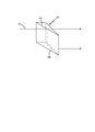
ここで、図3を参照して、ハーフミラープリズム33について説明する。図3は、ハーフミラープリズム33の副走査断面図である。ハーフミラープリズム33は、入射された光を、透過光と反射光に1:1の割合で分離するハーフミラー33aを備える。また、ハーフミラープリズム33は、光の進む方向を変換する機能を有する全反射面33bを備える。
Here, the
開口絞り32を出たビームは、ハーフミラープリズム33へ入射されるが、ハーフミラー33aで上下段の2つに分離され、全反射面33bで方向を変換された後、後述する上下段に配置されたポリゴンミラーへと出射される。
The beam exiting the
ここではハーフミラープリズムを用いたが、単体のハーフミラーと一般に使用されるミラーとを用いて同様の機能を有する光学系デバイスを構成することもできる。また、ハーフミラーによる光の分離割合は、上記の1:1に限定されるものではなく、他の光学系デバイスに条件に合わせて適宜設定することができる。 Although a half mirror prism is used here, an optical device having the same function can be configured using a single half mirror and a commonly used mirror. Further, the light separation ratio by the half mirror is not limited to the above 1: 1, and can be appropriately set according to the conditions of other optical system devices.
再び図2を参照して、光走査装置について説明する。光走査装置は、そのほか、シリンドリカルレンズ34a、34b、防音ガラス35、ポリゴンミラー36a、36b、偏向手段36、走査レンズ37a、37b、ミラー38、走査レンズ39a、39bを備えている。
With reference to FIG. 2 again, the optical scanning device will be described. In addition, the optical scanning device includes
ハーフミラープリズム33を出たビームは、上下段のそれぞれに合わせて配置されるシリンドリカルレンズ34a、34bにより、偏向反射面の近傍にて主走査方向に長い潜像へ変換される。偏向手段36は、回転軸に、上下2段にそれぞれポリゴンミラー36a、36bが周設されたものとされ、ポリゴンミラー36aに対しポリゴンミラー36bが回転方向へ角度φほどずれたものとされている。なお、ポリゴンミラー36a、36bは、一体的に形成されていてもよく、別体として組み付けてもよい。
The beam that exits the
回転方向へのずれ角φが均等である場合、ずれ角φは、ポリゴンミラーのミラー面の面数(M)に対し、π/Mで表すことができる。その面数が4である場合、ずれ角φはπ/4、すなわち45degとなる。このずれ角が45degである場合、上段のポリゴンミラー36aにより走査を開始し、その後に下段のポリゴンミラー36bにより走査を開始するまでの間隔と、下段のポリゴンミラー36bにより走査を開始し、その後に上段のポリゴンミラー36aにより走査を開始するまでの間隔は同じ間隔となり、どのタイミングのビームが上段で反射され、どのタイミングのビームが下段で反射されて走査を行っているのかを見分けることができない。
When the shift angle φ in the rotation direction is uniform, the shift angle φ can be expressed by π / M with respect to the number of mirror surfaces (M) of the polygon mirror. When the number of faces is 4, the deviation angle φ is π / 4, that is, 45 deg. When the deviation angle is 45 deg, scanning is started by the
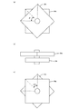
そこで、このミラー面のずれ角φを不均等にする。具体的には、図4(a)に示すように、上段のポリゴンミラー36aから下段のポリゴンミラー36bを見た場合のミラー面のずれ角をφ1とし、図4(c)に示すように、下段のポリゴンミラー36bから上段のポリゴンミラー36aを見た場合のミラー面のずれ角をφ2として、φ1=π/M+α、φ2=π/M−αとなるように、±αの角度差を設けてミラー面を配置する。なお、図4(a)の場合の側方から見た図が、図4(b)である。
Therefore, the deviation angle φ of the mirror surface is made uneven. Specifically, as shown in FIG. 4 (a), when the
例えば、ミラー面が4面で、角度ずれ量αが1°あると、φ1=46°、φ2=44°となる。この場合、上段のポリゴンミラー36aにより走査を開始し、その後に下段のポリゴンミラー36bにより走査を開始するまでの間隔は、下段のポリゴンミラー36bにより走査を開始し、その後に上段のポリゴンミラー36aにより走査を開始するまでの間隔より長くなり、間隔が長いほうが上段のポリゴンミラー36aにより走査したと判断でき、間隔が短いほうが下段のポリゴンミラー36bにより走査したと判断することができる。したがって、角度ずれ量αを設けることにより、その間隔からいずれの段により走査を行っているかを検出することができる。
For example, if there are four mirror surfaces and the angle deviation α is 1 °, φ1 = 46 ° and φ2 = 44 °. In this case, scanning is started by the
この角度ずれ量αの範囲は、ポリゴンミラーを組み立てるにあたって部品公差が大きなパラメータとなる。この公差とは、規定値と実物の値との差で、法令で許容される範囲で、機械加工でいう許し代である。例えば、部品公差を±0.25degとすると、α=0.25にしてもφ1=φ2となり、ポリゴンミラーの上段と下段を検出することができない。また、αが0.25未満になると、φ1とφ2の大小関係が逆転してしまい、ポリゴンミラーの上段と下段を検出することはできるが、その結果が上下段で逆の結果となる。このため、αが0.25を超える値でなければならない。 The range of the angular deviation amount α is a parameter having a large component tolerance in assembling the polygon mirror. This tolerance is the difference between the specified value and the actual value, and is the allowance in machining within the range allowed by law. For example, if the component tolerance is ± 0.25 deg, even if α = 0.25, φ1 = φ2, and the upper and lower stages of the polygon mirror cannot be detected. When α is less than 0.25, the magnitude relationship between φ1 and φ2 is reversed, and the upper and lower stages of the polygon mirror can be detected, but the result is the opposite of the upper and lower stages. For this reason, α must be a value exceeding 0.25.
また、部品公差を±0.5degとすると、α=0.5にしてもφ1=φ2となり、ポリゴンミラーの上段と下段を検出することができない。このため、α=0.5を超える値でなければならない。例えば、α=0.5005とすることができるが、この0.5005は、0.5に対し、わずか0.0005程大きくしただけであるが、高速クロックによりカウントを行うため、検知信号の間隔をカウントする値の差分が数百以上の差分があるので上下段の検出は十分に可能である。 Further, if the component tolerance is ± 0.5 deg, even if α = 0.5, φ1 = φ2, and the upper and lower stages of the polygon mirror cannot be detected. For this reason, the value must exceed α = 0.5. For example, α can be set to 0.5005, but this 0.5005 is only about 0.0005 larger than 0.5, but since the count is performed by the high-speed clock, the interval of the detection signal Since there is a difference of several hundred or more, the upper and lower stages can be sufficiently detected.
したがって、角度ずれ量αの最小値は、部品公差が±0.25degである場合には、αはその公差の絶対値0.25degを超える値、例えば0.2505degとすることができる。また、部品公差が±0.5degである場合には、αはその公差の絶対値0.5degを超える値、例えば0.5005degとすることができる。一方、角度ずれ量αの最大値は、αが大きくなると検知信号の間隔が短い段のミラー面で感光体ドラムを走査できる有効書き込み幅に相当する偏向角が小さくなり、主走査幅を走査するための制御クロックを大幅に高速化する必要があることから、45°に対して約2〜3%の約0.9〜1.35°が好ましい。 Therefore, when the component tolerance is ± 0.25 deg, the minimum value of the angle deviation amount α can be a value exceeding the absolute value of the tolerance 0.25 deg, for example, 0.2505 deg. Further, when the component tolerance is ± 0.5 deg, α can be a value exceeding the absolute value of the tolerance 0.5 deg, for example, 0.5005 deg. On the other hand, the maximum value of the angle shift amount α is such that when α is increased, the deflection angle corresponding to the effective writing width that can scan the photosensitive drum with the mirror surface with a short detection signal interval decreases, and the main scanning width is scanned. For this reason, it is necessary to significantly increase the speed of the control clock. Therefore, about 0.9 to 1.35 °, which is about 2 to 3% with respect to 45 °, is preferable.
この光走査装置では、角度ずれ量αを設けた偏向手段36を備えることで、いずれの段により走査を行っているかを検出することができる。この光走査装置において、角度ずれ量αが0の偏向手段36を取り付けた場合、上下段の検出はできないものの、上記間隔が等間隔で一定であることを検出し、角度差がないことを検知することができる。このため、製造時に、角度差がないように製作した場合であっても、このようにして検出した検知信号の間隔が異なるときは、製造段階で角度差が生じていることを検知することができる。
In this optical scanning device, it is possible to detect which stage the scanning is performed by including the deflecting
実際の走査について説明すると、図5(a)に示すように、共通の光源からの上段ビームB1が感光体ドラム(被走査面)を走査しているときは、下段のビームB2は被走査面上にビームが到達しないように、遮光部材40により遮光するようにする。
The actual scanning will be described. As shown in FIG. 5A, when the upper beam B1 from the common light source is scanning the photosensitive drum (scanned surface), the lower beam B2 is scanned. The
また、共通の光源からの下段ビームB2が被走査面を走査しているときは、図5(b)に示すように、上段ビームB1は被走査面上にビームが到達しないように、遮光部材40により遮光するようにする。 Further, when the lower stage beam B2 from the common light source scans the surface to be scanned, as shown in FIG. 5B, the upper stage beam B1 prevents the beam from reaching the surface to be scanned. The light is shielded by 40.
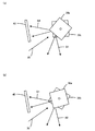
図6を参照して、光走査装置が備える制御部の構成およびその制御部により行われる走査の制御について詳細に説明する。 With reference to FIG. 6, the configuration of the control unit included in the optical scanning device and the scanning control performed by the control unit will be described in detail.
この制御部は、光源制御部50と、データ選択部51と、偏向走査段検出部52とを備える。偏向走査段検出部52は、同期検知計測部52aと、比較判定部52bとを備える。
This control unit includes a light
光源制御部50は、2つの光源からポリゴンミラー36aとポリゴンミラー36bとに出射する各ビームを制御するために、各光源に対し変調信号を出力する。各光源から出射されたビームは、上段のポリゴンミラー36aのミラー面と、下段のポリゴンミラー36bのミラー面とに入射する。ポリゴンミラー36a、36bの回転によりビームは、主走査方向へ走査し、図2に示す走査レンズ38とミラー39とを介して感光体ドラム10a〜10dを走査する。ポリゴンミラー36a、36bの回転位置は、走査先端位置に配置された受光素子53a、53bにより主走査の書き出し位置を示す同期検知信号として検出する。ここでは、受光素子53a、53bで同時にビームを検知していることから同期検知信号としている。
The light
受光素子53a、53bで検出された同期検知信号は、偏向走査段検出部52へ入力され、偏向走査段検出部52の同期検知計測部52aが同期検知信号の間隔を計測する。同期検知計測部52aにより計測された結果は、比較判定部52bへ出力され、比較判定部52bが所定の値と比較する。この所定の値は、ポリゴンミラー36a、36bの上下段を判定するための限界値、もしくは固定値、または同期検知計測部52aで計測された直前の値とすることができる。
The synchronization detection signals detected by the
固定値である場合、上段のポリゴンミラー36aにより反射されたビームを検知した受光素子53a、53bが出力した同期検知信号を受けてから、その後に下段のポリゴンミラー36bにより反射されたビームを検知した受光素子53a、53bが出力した同期検知信号を受けるまで間隔Taと、下段のポリゴンミラー36bにより反射されたビームを検知した受光素子53a、53bが出力した同期検知信号を受けてから、その後に上段のポリゴンミラー36aにより反射されたビームを検知した受光素子53a、53bが出力した同期検知信号を受けるまで間隔Tbとの平均値(Ta+Tb)/2とすることができる。
In the case of a fixed value, the beam reflected by the
所定の値が同期検知計測部52aで計測された直前の値である場合、間隔Taに比較して、間隔Tbが長い光学系デバイスでは、同期検知計測部52aにより計測された結果が交互に間隔が長いものと短いものを繰り返すことから、その直前の計測結果と現在の計測結果とを比較し、現在の計測結果のほうが大きい場合には下段、小さい場合には上段を走査したと判断することができる。この判定結果から、ミラー面の走査を上段と下段を判別する偏向走査段信号を比較判定部52bからデータ選択部51へ出力する。
When the predetermined value is a value immediately before being measured by the synchronization
データ選択部51では、比較判定部52bからの偏向走査段信号に基づき画像処理部54からの画像データを合成する。画像処理部54は、ブラック(K)、シアン(C)、イエロー(Y)、マゼンタ(M)の4色の画像データをデータ選択部51へ入力する。光走査装置と感光体ドラムの配置により、各光源で作像するトナー色を決定する。ここでは、1つの光源でブラックとシアンを、もう1つの光源でイエローとマゼンタを作像すると仮定すると、データ選択部51では比較判定部52bからの偏向走査段信号に基づき、ブラックとシアンを1つの光源用の画像データとして合成し、もう1つの光源用にはイエローとマゼンタの画像データを合成し、光源制御部50へ出力する。光源制御部50は、各光源に対し変調信号を出力し、各光源がこれを基に各ビームを出射し、所望の静電潜像を形成する。
The
本発明では、1つの光源で2色の画像を形成することを特徴とし、この図6に示した実施形態では、2つの光源で計4色の画像を形成しているが、光源数は2つに限られるものではなく、例えば、高速で画像形成を行うために、2色の画像を形成する光源を2つ用い、4色の画像を計4つの光源を使用して形成することもできる。また、光源には、単独の光源素子で1つの発光点をもつ半導体レーザだけではなく、複数の発光点を有する半導体レーザダイオードアレイや、二次元に発光点を配置した面発光型半導体レーザを光源に使用することもできる。本発明の構成を採用することで、発光点数を削減することができるため、特に、多くの発光点を有する面発光型半導体レーザは、画像形成装置全体での部品点数を削減することができることから有効である。 In the present invention, two color images are formed by one light source. In the embodiment shown in FIG. 6, a total of four color images are formed by two light sources, but the number of light sources is two. For example, in order to perform image formation at high speed, two light sources that form two-color images can be used, and four-color images can be formed using a total of four light sources. . The light source is not only a semiconductor laser having a single light emitting point with a single light source element, but also a semiconductor laser diode array having a plurality of light emitting points and a surface emitting semiconductor laser in which light emitting points are two-dimensionally arranged. Can also be used. Since the number of light emitting points can be reduced by employing the configuration of the present invention, the surface emitting semiconductor laser having a large number of light emitting points can reduce the number of parts in the entire image forming apparatus. It is valid.
図7は、光走査装置が備える制御部の別の構成例を示した図である。この実施形態では、さらに、制御部が、偏向動作判定部55を備える構成とされている。
FIG. 7 is a diagram illustrating another configuration example of the control unit included in the optical scanning device. In this embodiment, the control unit further includes a deflection
この実施形態では、受光素子53a、53bで検出された同期検知信号は、偏向走査段検出部52と偏向動作判定部55とへ入力される。また、ミラー面の走査を上段と下段を判別する偏向走査段信号が、比較判定部52bからデータ選択部51と偏向動作判定部55とへ出力される。
In this embodiment, the synchronization detection signals detected by the
偏向動作判定部55には、受光素子53a、53bで検出した同期検知信号と、偏向走査段検出部52で生成した偏向走査段信号とが入力される。受光素子53a、53bは、ポリゴンモータの回転に合わせて、上段と下段の同期検知信号を交互に検出する。1つの光源では、上段の走査で1回、下段の走査で1回の同期検知信号を検出するため、ポリゴンミラー36aとポリゴンミラー36bのずれ角が不均等である場合、同期検知信号の間隔が大小交互に形成され、偏向走査段信号が上段と下段を交互に示す信号となる。したがって、ポリゴンモータの回転が正常動作し、ポリゴンミラー36a、36bが正常に回転している場合は、偏向走査段信号が上段と下段を交互に表すものとなる。
To the deflection
これに対し、ポリゴンモータの回転が正常動作せず、ポリゴンミラー36a、36bが正常に回転していない場合は、上述したようにミラー間のずれ角が2〜3%程度の角度差しかないことから、微小な回転不安定状態であっても、上述したような同期検知信号の間隔が大小交互に形成されたものにはならない。このため、偏向走査段信号も、上段と下段を交互に表したものにはならない。これでは、データ選択部51が偏向走査段信号に基づき画像データの色を決定する際、誤った色を選択してしまい、最終出力画像に異常を生じてしまう。
On the other hand, if the polygon motor does not rotate normally and the polygon mirrors 36a and 36b do not rotate normally, the deviation angle between the mirrors is only about 2 to 3% as described above. Even in a minute rotational unstable state, the intervals of the synchronization detection signals as described above are not alternately formed. For this reason, the deflection scanning stage signal also does not represent the upper stage and the lower stage alternately. In this case, when the
偏向動作判定部55は、この偏向走査段信号から、ポリゴンモータの回転が安定し、正常に動作しているか否かを判定し、正常動作していると判定した場合は、画像形成動作を実行させ、正常動作でないと判定した場合は、画像処理部54に対して通知し、画像形成動作を停止させることができる。
Based on this deflection scanning stage signal, the deflection
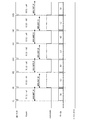
図8は、ポリゴンモータの回転が安定し、正常に動作している場合の光走査装置の制御タイミングを示した図である。図8に示すDETP_Nは、図6または図7に示す受光素子53により出力された同期検知信号である。ポリゴンミラーが1つで、ミラー面が1段である場合には、1つの同期検知信号が検出されるが、ポリゴンミラーが2つで、ミラー面が2段である場合には、2つの同期検知信号が検出される。偏向走査段検出部52の同期検知計測部52aは、DETP_N信号の間隔を計測するカウンタを有する。このカウンタの制御クロックは、光源を1画素単位で制御するクロックのため、ローエンドの装置でも約10MHzの周波数で動作し、ハイエンドの装置では約200MHzの周波数で動作する高速クロックである。
FIG. 8 is a diagram showing the control timing of the optical scanning device when the rotation of the polygon motor is stable and operating normally. DETP_N shown in FIG. 8 is a synchronization detection signal output by the light receiving element 53 shown in FIG. 6 or FIG. When there is one polygon mirror and one mirror surface, one synchronization detection signal is detected. However, when there are two polygon mirrors and two mirror surfaces, two synchronization signals are detected. A detection signal is detected. The synchronization
比較判定部52bが比較する値が固定値である場合、同期検知信号(DETP_N)入力タイミングのカウンタの計測値を固定値(MRLIMIT_R)と比較し、固定値以上であれば偏向走査段信号(mirrorside)をlowに、固定値未満であればmirrorsideをhighにする。具体的には、固定値以上であればlowを表す0に、固定値未満であればhighを表す1にする。図8では、(I)と(II)のDETP_N信号の間隔が固定値(MRLIMIT_R)未満となっているため、(II)のDETP_N信号を受信後、mirrorsideがhighにされている。
When the value to be compared by the
また、比較判定部52bが比較する値が、同期検知計測部52aが計測した直前の結果である場合、直前値であるa1と現在値であるb1を比較し、現在値が大きい場合にはmirrorsideをlowにする。直前値がb1で現在値がa2であり、現在値a2が直前値b1より小さい場合には、mirrorsideをhighにする。
Further, when the value compared by the
この図8には図示していないが、比較判定部52bが比較する値が固定値(MRLIMIT_R)である場合、その固定値は、制御部が有する記憶部に設定された値であり、固定値としては、同期検知信号の間隔からポリゴンミラーの上下段を判定可能な値を予め設定しておくことができる。画像形成装置が備える感光体ドラムの回転速度を変更した場合等、同期検知信号の間隔が変化すると、その変化幅に合わせて判定リミット値を変更することができるように任意の値を設定することが可能である。
Although not shown in FIG. 8, when the value to be compared by the
図8では、同期検知信号(DETP_N)の入力ごとにmirrorsideがhighとlowに切り替えられており、図7に示す構成を採用する場合、偏向動作判定部55は、ポリゴンモータの回転が安定し、正常動作していると判定する。この結果から、mirror_errorというエラー信号はlowのまま維持され、画像形成動作を実行させる。画像形成動作では、mirrorsideに基づいてデータ選択部51で複数色のデータを合成する。ブラックとシアンの画像を合成する場合、ブラックがポリゴンミラーの上段により走査し、シアンが下段で走査する色であると仮定する。mirrorsideがlowである場合、ブラックのデータ(k)を選択し、mirrorsideがhighである場合、シアンのデータ(c)を選択し、1つの光源を駆動する変調信号として合成する。これは、残りのイエロー、マゼンタについても同様である。
In FIG. 8, the mirrorside is switched between high and low for each input of the synchronization detection signal (DETP_N), and when the configuration shown in FIG. 7 is adopted, the deflection
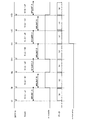
図9は、ポリゴンモータの回転が不安定で、正常に動作していない場合の光走査装置の制御タイミングを示した図である。この図9では、(I)〜(IV)のDETP_N期間においてmirrorsideがhighとlowが交互に切り替えられたものとなっている。しかしながら、(V)のDETP_N期間の検出間隔が固定値MRLIMIT_Rよりも大きい間隔になることが正常であるにもかかわらず、ポリゴンモータの回転が乱れ、固定値よりも小さい間隔になっている。このため、同期検知信号の入力ごとに偏向動作段信号がhighとlowに交互に切り替わらず、図7に示す構成を採用する場合、偏向動作判定部55は、エラー状態であることを検出し、正常動作でないと判定する。これにより、偏向動作判定部55は、mirror_errorというエラー信号をhighにし、画像処理部54に対して画像形成動作を停止させる通知処理を行う。
FIG. 9 is a diagram showing the control timing of the optical scanning device when the rotation of the polygon motor is unstable and not operating normally. In FIG. 9, the mirrorside is alternately switched between high and low during the DETP_N period of (I) to (IV). However, although it is normal that the detection interval of the DETP_N period of (V) is larger than the fixed value MRLIMIT_R, the rotation of the polygon motor is disturbed and the interval is smaller than the fixed value. For this reason, when the configuration shown in FIG. 7 is adopted in which the deflection operation stage signal is not alternately switched between high and low every time the synchronization detection signal is input, the deflection
これまで本発明を実施の形態をもって説明してきたが、本発明は上述した実施の形態に限定されるものではなく、他の実施の形態、追加、変更、削除など、当業者が想到することができる範囲内で変更することができ、いずれの態様においても本発明の作用・効果を奏する限り、本発明の範囲に含まれるものである。制御部による処理は、プログラムとして構成することができ、光走査装置により実行させることができる。このプログラムは、コンピュータ読み取り可能な媒体であればいかなる媒体に格納して提供することができ、フレキシブルディスク、MDディスク、SDカード、CD−ROM、DVD−ROM等に格納して提供することができる。 Although the present invention has been described with the embodiments, the present invention is not limited to the above-described embodiments, and other embodiments, additions, changes, deletions, and the like may occur to those skilled in the art. It can be changed within the range that can be done, and any embodiment is included in the scope of the present invention as long as the effects of the present invention are exhibited. The processing by the control unit can be configured as a program and can be executed by the optical scanning device. This program can be provided by being stored on any computer-readable medium, and can be provided by being stored on a flexible disk, MD disk, SD card, CD-ROM, DVD-ROM or the like. .
10a〜10d…感光体ドラム、11a〜11d…帯電ユニット、12a〜12d…トナーカートリッジ、13a〜13d…転写ローラ、14…中間転写ベルト、15…中間転写ローラ、16…中間転写ベルトクリーニング装置、17…転写装置、18…給紙レジストセンサ、19…定着装置、20…排紙装置、21…光走査装置、30…半導体レーザ、31…カップリングレンズ、32…開口絞り、33…ハーフミラープリズム、33a…ハーフミラー、33b…全反射面、34a、34b…シリンドリカルレンズ、35…防音ガラス、36…偏向手段、36a、36b…ポリゴンミラー、37a、37b…走査レンズ、38…ミラー、39a、39b…走査レンズ、40…遮光部材、50…光源制御部、51…データ選択部、52…偏向走査段検出部、52a…同期検知計測部、52b…比較判定部、53…受光素子、54…画像処理部、55…偏向動作判定部 10a to 10d ... photosensitive drum, 11a to 11d ... charging unit, 12a to 12d ... toner cartridge, 13a to 13d ... transfer roller, 14 ... intermediate transfer belt, 15 ... intermediate transfer roller, 16 ... intermediate transfer belt cleaning device, 17 DESCRIPTION OF SYMBOLS ... Transfer device, 18 ... Paper feed registration sensor, 19 ... Fixing device, 20 ... Paper discharge device, 21 ... Optical scanning device, 30 ... Semiconductor laser, 31 ... Coupling lens, 32 ... Aperture stop, 33 ... Half mirror prism, 33a ... Half mirror, 33b ... Total reflection surface, 34a, 34b ... Cylindrical lens, 35 ... Soundproof glass, 36 ... Deflection means, 36a, 36b ... Polygon mirror, 37a, 37b ... Scanning lens, 38 ... Mirror, 39a, 39b ... Scanning lens, 40 ... light shielding member, 50 ... light source control unit, 51 ... data selection unit, 52 ... deflection査段 detection unit, 52a ... synchronization detection measurement unit, 52 b ... comparison section, 53 ... light-receiving element, 54 ... image processing unit, 55 ... deflection operation determination unit
Claims (19)
前記偏向手段により走査される前記ビームを検知する受光手段と、
前記受光手段による前記ビームの検知間隔に基づき、各段の前記多面反射鏡により走査を行うタイミングを検出する検出手段とをさらに備え、
前記偏向手段が、前記受光手段による前記ビームの検知間隔が等間隔にならないように各段の前記多面反射鏡が回転方向へ角度をずらして配設されていることを特徴とする、光走査装置。 A deflecting means having a rotating shaft and a multi-faceted reflecting mirror provided at least in two stages on the rotating shaft and shifted in the rotational direction, and a beam from the light source are divided into at least two parts, Splitting means for causing the beams to be incident on the multi-surface reflecting mirrors of different stages, and each beam reflected by the multi-surface reflecting mirrors of the different stages rotating about the rotation axis scans different surfaces to be scanned. An optical scanning device,
A light receiving means for detecting the beam scanned by the deflection means;
Detecting means for detecting the timing of scanning by the multi-surface reflecting mirror at each stage based on the detection interval of the beam by the light receiving means;
The optical scanning device characterized in that the deflecting means is arranged such that the multi-surface reflecting mirrors of each stage are shifted in the rotation direction so that the detection intervals of the beams by the light receiving means are not equal. .
前記偏向手段により走査される前記ビームを検知するステップと、
前記受光手段による前記ビームの検知間隔に基づき、各段の前記多面反射鏡により走査を行うタイミングを検出するステップとを含み、
前記偏向手段が、前記受光手段による前記ビームの検知間隔が等間隔にならないように各段の前記多面反射鏡が回転方向へ角度をずらして配設されていることを特徴とする、制御方法。 A deflecting means having a rotating shaft and a multi-faceted reflecting mirror provided at least in two stages on the rotating shaft and shifted in the rotational direction, and a beam from the light source are divided into at least two parts, Splitting means for causing the beams to be incident on the multi-surface reflecting mirrors at different stages, and each beam reflected by the multi-surface reflecting mirrors at the different stages rotating about the rotation axis is scanned differently. A control method executed to scan a surface at a predetermined timing,
Detecting the beam scanned by the deflection means;
Detecting the timing of scanning by the multi-surface reflecting mirrors of each stage based on the detection interval of the beam by the light receiving means,
The control method according to claim 1, wherein the deflecting means is arranged such that the multi-surface reflecting mirrors of each stage are shifted in the rotation direction so that the detection intervals of the beams by the light receiving means are not equal.
Priority Applications (1)
| Application Number | Priority Date | Filing Date | Title |
|---|---|---|---|
| JP2009181168A JP5310365B2 (en) | 2008-08-22 | 2009-08-04 | Optical scanning apparatus, image forming apparatus, control method, program, and recording medium |
Applications Claiming Priority (3)
| Application Number | Priority Date | Filing Date | Title |
|---|---|---|---|
| JP2008213860 | 2008-08-22 | ||
| JP2008213860 | 2008-08-22 | ||
| JP2009181168A JP5310365B2 (en) | 2008-08-22 | 2009-08-04 | Optical scanning apparatus, image forming apparatus, control method, program, and recording medium |
Publications (2)
| Publication Number | Publication Date |
|---|---|
| JP2010072634A true JP2010072634A (en) | 2010-04-02 |
| JP5310365B2 JP5310365B2 (en) | 2013-10-09 |
Family
ID=42204414
Family Applications (1)
| Application Number | Title | Priority Date | Filing Date |
|---|---|---|---|
| JP2009181168A Expired - Fee Related JP5310365B2 (en) | 2008-08-22 | 2009-08-04 | Optical scanning apparatus, image forming apparatus, control method, program, and recording medium |
Country Status (1)
| Country | Link |
|---|---|
| JP (1) | JP5310365B2 (en) |
Cited By (3)
| Publication number | Priority date | Publication date | Assignee | Title |
|---|---|---|---|---|
| JP2012063595A (en) * | 2010-09-16 | 2012-03-29 | Ricoh Co Ltd | Optical scanner and image forming apparatus |
| EP2500174A1 (en) | 2011-03-17 | 2012-09-19 | Ricoh Company, Ltd. | Image forming apparatus |
| CN103837984A (en) * | 2012-11-26 | 2014-06-04 | 株式会社理光 | Optical scanning apparatus, method for performing the same and image forming apparatus |
Citations (3)
| Publication number | Priority date | Publication date | Assignee | Title |
|---|---|---|---|---|
| JP2005266015A (en) * | 2004-03-16 | 2005-09-29 | Ricoh Co Ltd | Image forming apparatus |
| JP2008058800A (en) * | 2006-09-01 | 2008-03-13 | Ricoh Co Ltd | Optical scanner and image forming apparatus |
| JP2009047924A (en) * | 2007-08-20 | 2009-03-05 | Ricoh Co Ltd | Multibeam light source apparatus, multibeam scanner, and image forming apparatus |
-
2009
- 2009-08-04 JP JP2009181168A patent/JP5310365B2/en not_active Expired - Fee Related
Patent Citations (3)
| Publication number | Priority date | Publication date | Assignee | Title |
|---|---|---|---|---|
| JP2005266015A (en) * | 2004-03-16 | 2005-09-29 | Ricoh Co Ltd | Image forming apparatus |
| JP2008058800A (en) * | 2006-09-01 | 2008-03-13 | Ricoh Co Ltd | Optical scanner and image forming apparatus |
| JP2009047924A (en) * | 2007-08-20 | 2009-03-05 | Ricoh Co Ltd | Multibeam light source apparatus, multibeam scanner, and image forming apparatus |
Cited By (6)
| Publication number | Priority date | Publication date | Assignee | Title |
|---|---|---|---|---|
| JP2012063595A (en) * | 2010-09-16 | 2012-03-29 | Ricoh Co Ltd | Optical scanner and image forming apparatus |
| EP2500174A1 (en) | 2011-03-17 | 2012-09-19 | Ricoh Company, Ltd. | Image forming apparatus |
| US20120236381A1 (en) * | 2011-03-17 | 2012-09-20 | Ricoh Company, Ltd. | Image Forming Apparatus |
| JP2012194468A (en) * | 2011-03-17 | 2012-10-11 | Ricoh Co Ltd | Image forming device |
| CN103837984A (en) * | 2012-11-26 | 2014-06-04 | 株式会社理光 | Optical scanning apparatus, method for performing the same and image forming apparatus |
| US9170523B2 (en) | 2012-11-26 | 2015-10-27 | Ricoh Company, Limited | Optical scanning apparatus, method for performing the same and image forming apparatus |
Also Published As
| Publication number | Publication date |
|---|---|
| JP5310365B2 (en) | 2013-10-09 |
Similar Documents
| Publication | Publication Date | Title |
|---|---|---|
| JP4921896B2 (en) | Optical scanning apparatus and image forming apparatus | |
| US10254677B2 (en) | Light scanning apparatus | |
| US8654165B2 (en) | Optical scanning device and image forming apparatus | |
| JP4838461B2 (en) | Image forming apparatus | |
| JP2006035725A (en) | Color imaging device and process cartridge | |
| JP5750956B2 (en) | Image forming apparatus | |
| JP5310365B2 (en) | Optical scanning apparatus, image forming apparatus, control method, program, and recording medium | |
| KR101814121B1 (en) | Electrophotograpohic image forming apparatus | |
| JP2014115626A (en) | Optical scanner and image forming apparatus | |
| JP5732923B2 (en) | Optical scanning apparatus, image forming apparatus, and optical scanning method | |
| JP2001311898A (en) | Light beam scanning driving device and image forming device | |
| JP4032655B2 (en) | Image forming apparatus | |
| JP3906613B2 (en) | Multicolor image forming apparatus | |
| JP2009169362A (en) | Light beam scanner and digital writer | |
| JP4411054B2 (en) | Optical scanning device and image forming apparatus using the same | |
| JP5471999B2 (en) | Optical scanning apparatus and image forming apparatus | |
| JP4524116B2 (en) | Image forming apparatus | |
| JP3911404B2 (en) | Image forming apparatus | |
| JP2011186202A (en) | Optical scanner and image forming apparatus equipped with the same | |
| JPH1120239A (en) | Color image forming system | |
| JP2006181835A (en) | Image forming device | |
| JP2011257478A (en) | Optical scanner and image forming apparatus | |
| KR20230004094A (en) | Laser scanning unit for processing multiple beams with single synchronization detection sensor | |
| JP2011025446A (en) | Optical writing apparatus and image forming apparatus | |
| JP2012063625A (en) | Optical scanner and image forming device |
Legal Events
| Date | Code | Title | Description |
|---|---|---|---|
| A621 | Written request for application examination |
Free format text: JAPANESE INTERMEDIATE CODE: A621 Effective date: 20120528 |
|
| A977 | Report on retrieval |
Free format text: JAPANESE INTERMEDIATE CODE: A971007 Effective date: 20130205 |
|
| A131 | Notification of reasons for refusal |
Free format text: JAPANESE INTERMEDIATE CODE: A131 Effective date: 20130212 |
|
| A521 | Written amendment |
Free format text: JAPANESE INTERMEDIATE CODE: A523 Effective date: 20130404 |
|
| TRDD | Decision of grant or rejection written | ||
| A01 | Written decision to grant a patent or to grant a registration (utility model) |
Free format text: JAPANESE INTERMEDIATE CODE: A01 Effective date: 20130604 |
|
| A61 | First payment of annual fees (during grant procedure) |
Free format text: JAPANESE INTERMEDIATE CODE: A61 Effective date: 20130617 |
|
| R151 | Written notification of patent or utility model registration |
Ref document number: 5310365 Country of ref document: JP Free format text: JAPANESE INTERMEDIATE CODE: R151 |
|
| LAPS | Cancellation because of no payment of annual fees |