JP2010072317A - Apparatus for manufacturing color filter - Google Patents
Apparatus for manufacturing color filter Download PDFInfo
- Publication number
- JP2010072317A JP2010072317A JP2008239388A JP2008239388A JP2010072317A JP 2010072317 A JP2010072317 A JP 2010072317A JP 2008239388 A JP2008239388 A JP 2008239388A JP 2008239388 A JP2008239388 A JP 2008239388A JP 2010072317 A JP2010072317 A JP 2010072317A
- Authority
- JP
- Japan
- Prior art keywords
- film material
- detection
- mark
- ink
- longitudinal direction
- Prior art date
- Legal status (The legal status is an assumption and is not a legal conclusion. Google has not performed a legal analysis and makes no representation as to the accuracy of the status listed.)
- Granted
Links
Images


Abstract
Description
本発明は、液晶パネル等に用いられるカラーフィルタの製造装置に関する。 The present invention relates to an apparatus for manufacturing a color filter used for a liquid crystal panel or the like.
長尺状の基材を装着する原反装着ユニットと、基材の表面に着色層用インクを供給するためのインクジェットユニットと、ブラックマトリクス及び着色層が形成された長尺状の基材を巻き取るための巻取りユニットと、を備えたカラーフィルタの製造装置が知られている(例えば、特許文献1)。 A raw fabric mounting unit for mounting a long base material, an inkjet unit for supplying colored layer ink to the surface of the base material, and a long base material on which a black matrix and a colored layer are formed are wound. 2. Description of the Related Art A color filter manufacturing apparatus including a winding unit for taking is known (for example, Patent Document 1).
インクジェットユニットを用いたカラーフィルタの製造装置では、フィルタ形成領域の所定位置にインクを噴射して塗布するためにフィルタ形成領域の周辺に複数のアライメントマークが設けられたフィルム材が使用される。そして、このようなカラーフィルタの製造装置では、フィルタ形成領域の周辺に設けられた複数のアライメントマークに基づいてフィルタ形成領域毎に位置調整をする必要がある。そのため、複数のフィルタ形成領域が所定間隔を開けて長手方向に並べられたフィルム材を使用した場合には、フィルタ形成領域が移動する度にフィルム材の搬送を停止し、インクジェットユニットの位置調整を行わなければならない。従って、フィルム材の移動が間欠的となってしまう。 In a color filter manufacturing apparatus using an ink jet unit, a film material provided with a plurality of alignment marks around a filter forming region is used in order to eject and apply ink to a predetermined position of the filter forming region. In such a color filter manufacturing apparatus, it is necessary to adjust the position of each filter formation region based on a plurality of alignment marks provided around the filter formation region. Therefore, when using a film material in which a plurality of filter forming regions are arranged in the longitudinal direction at predetermined intervals, the conveyance of the film material is stopped every time the filter forming region moves and the position of the inkjet unit is adjusted. It must be made. Therefore, the movement of the film material becomes intermittent.
そこで、本発明は、複数のフィルタ形成領域が所定間隔を開けて長手方向に並べられたフィルム材を使用して連続的にカラーフィルタの製造を行うことができるカラーフィルタ製造装置を提供することを目的とする。 Therefore, the present invention provides a color filter manufacturing apparatus capable of continuously manufacturing a color filter by using a film material in which a plurality of filter forming regions are arranged in the longitudinal direction at predetermined intervals. Objective.
本発明のカラーフィルタ製造装置は、複数のフィルタ形成領域が所定間隔を開けて長手方向に並べられ、長手方向と交差する直線上に位置する一対の検出部を有するタイミング調整部が前記フィルタ形成領域を避けるように設けられたフィルム材を長手方向に沿って搬送する搬送手段と、前記フィルタ形成領域にインクを噴射して塗布するインク噴射手段と、前記搬送手段にて搬送された状態の前記フィルム材から前記一対の検出部を検出する検出手段と、前記検出手段が検出した前記検出部毎の検出タイミングに基づいて搬送方向に対する前記フィルム材の傾きに伴うインクの噴射位置のずれが補正されるように前記インク噴射手段の位置を制御し、かつ、前記検出手段が検出した前記一対の検出部に基づいて前記フィルタ形成領域にインクが噴射されるように前記インク噴射手段の動作を制御する制御手段と、を備えている(請求項1)。 In the color filter manufacturing apparatus of the present invention, a plurality of filter formation regions are arranged in the longitudinal direction at predetermined intervals, and the timing adjustment unit having a pair of detection units located on a straight line intersecting the longitudinal direction includes the filter formation region. The film in a state of being transported by the transport means, the transport means for transporting the film material provided along the longitudinal direction, the ink ejecting means for spraying and applying ink to the filter forming region, and the film transported by the transport means Based on the detection means for detecting the pair of detection units from the material and the detection timing for each of the detection units detected by the detection unit, the deviation of the ink ejection position due to the inclination of the film material with respect to the transport direction is corrected. The position of the ink ejecting means is controlled as described above, and the ink ejecting means is inserted into the filter forming region based on the pair of detecting portions detected by the detecting means. There is provided a control means for controlling the operation of said ink injection means so as to be injected, a (claim 1).
このカラーフィルタの製造装置によれば、搬送された状態のフィルム材から長手方向と交差する直線上に位置した一対の検出部が検出され、検出部毎の検出タイミングに基づいてインク噴射手段の位置が調整される。フィルム材は長手方向に搬送されているため、フィルム材に搬送方向に対する傾きが生じた場合には、一対の検出部と検出手段との位置関係に変化が生じるので、検出タイミングにも検出部毎に変化が生じる。このため、検出部毎の検出タイミングに基づいてインク噴射手段の位置を制御することによって、フィルム材の傾きに伴うインクの噴射位置のずれを補正することができる。また、このカラーフィルタの製造装置によれば、フィルム材を搬送しながら、検出された一対の検出部に基づいてインク噴射手段がインクを噴射するようにその動作が制御される。このため、例えば、検出された一対の検出部の検出タイミングに関連付けてインクを噴射するタイミングを予め設定しておけば、フィルタ形成領域の適切な位置にインクを噴射することができる。そして、インク噴射手段の位置の調整と噴射タイミングの調整とはフィルム材を搬送しながら行うことができるので、フィルタ形成領域が移動する度にフィルム材の搬送を停止しなくてよい。従って、複数のフィルタ形成領域が所定間隔を開けて長手方向に並べられたフィルム材を使用して連続的にカラーフィルタの製造を行うことができる。 According to this color filter manufacturing apparatus, a pair of detection units positioned on a straight line that intersects the longitudinal direction is detected from the film material in the conveyed state, and the position of the ink ejection unit is determined based on the detection timing of each detection unit. Is adjusted. Since the film material is conveyed in the longitudinal direction, when the film material is inclined with respect to the conveyance direction, the positional relationship between the pair of detection units and the detection means changes, so that the detection timing is also different for each detection unit. Changes. Therefore, by controlling the position of the ink ejecting unit based on the detection timing for each detection unit, it is possible to correct the deviation of the ink ejecting position due to the inclination of the film material. Further, according to this color filter manufacturing apparatus, the operation is controlled so that the ink ejecting means ejects ink based on the detected pair of detection units while conveying the film material. For this reason, for example, if the timing of ejecting ink is set in advance in association with the detected timing of the pair of detection units, the ink can be ejected to an appropriate position in the filter formation region. Since the adjustment of the position of the ink ejecting means and the adjustment of the ejection timing can be performed while transporting the film material, it is not necessary to stop the transport of the film material every time the filter forming region moves. Therefore, a color filter can be continuously manufactured using a film material in which a plurality of filter forming regions are arranged in the longitudinal direction at predetermined intervals.
本発明に係る一対の検出部は搬送方向と交差する方向にずれて位置していればよい。例えば、前記一対の検出部は、前記フィルム材の長手方向と直交する直線上に位置し、前記制御手段は、前記検出部毎の検出タイミングが同一となるように前記インク噴射手段の位置を制御してもよい(請求項2)。検出部毎の検出タイミングが同一となるように噴射手段の位置を制御することにより、フィルム材と噴射手段との位置関係が適切であることが補償されるので、フィルム材の傾きに伴うインクの噴射位置のずれを確実に補正できる。 The pair of detection units according to the present invention need only be shifted in the direction intersecting the transport direction. For example, the pair of detection units are positioned on a straight line orthogonal to the longitudinal direction of the film material, and the control unit controls the position of the ink ejecting unit so that the detection timing of each detection unit is the same. (Claim 2). By controlling the position of the ejection unit so that the detection timing of each detection unit is the same, it is compensated that the positional relationship between the film material and the ejection unit is appropriate. The deviation of the injection position can be corrected reliably.
本発明のカラーフィルタの製造装置の一態様において、前記フィルム材には、前記フィルタ形成領域の側方にカウント用マークが設けられており、前記カウント用マークの累計カウント数を保持する数値保持手段を更に備え、前記検出手段は、搬送された状態の前記フィルム材から前記カウント用マークを検出し、前記制御手段は、前記検出手段が検出した前記カウント用マークに基づいて前記数値保持手段が保持する前記累計カウント数のカウントアップ及び所定値における前記累計カウント数のリセットの少なくともいずれか一方を実行してもよい(請求項3)。この場合、フィルム材の搬送状態に応じてカウント用マークが検出され、累計カウント数がカウントアップされる。このため、カラーフィルタの製造装置の稼働状況を把握することができる。また、適切な所定値にて累計カウント数がリセットされるため、累計カウント数の桁あふれを防止することができる。 In one aspect of the color filter manufacturing apparatus of the present invention, the film material is provided with a count mark on a side of the filter formation region, and a numerical value holding means for holding a cumulative count number of the count mark The detection means detects the counting mark from the film material in the conveyed state, and the control means holds the numerical value holding means based on the counting mark detected by the detection means. The cumulative count number may be counted up and / or the cumulative count number may be reset to a predetermined value. In this case, a count mark is detected according to the conveyance state of the film material, and the cumulative count number is counted up. For this reason, it is possible to grasp the operating status of the color filter manufacturing apparatus. In addition, since the cumulative count number is reset with an appropriate predetermined value, overflow of the cumulative count number can be prevented.
本発明のカラーフィルタの製造装置の一態様において、前記フィルム材には、搬送方向と直交する方向のずれを調整するためのアライメントマークが前記フィルタ形成領域の側方に設けられており、前記搬送手段にて搬送された状態の前記フィルム材から前記アライメントマークを検出する位置検出手段を更に備え、前記制御手段は、前記位置検出手段が検出した前記アライメントマークに基づいて前記インク噴射手段の位置を制御してもよい(請求項4)。この場合、フィルム材を搬送しながらフィルム材に生じた搬送方向と直交する方向のずれに対応してインク噴射手段の位置を調整することができる。 In one aspect of the color filter manufacturing apparatus of the present invention, the film material is provided with an alignment mark on a side of the filter formation region for adjusting a deviation in a direction orthogonal to the transport direction, and the transport Position detecting means for detecting the alignment mark from the film material conveyed by the means, and the control means determines the position of the ink ejecting means based on the alignment mark detected by the position detecting means. You may control (Claim 4). In this case, the position of the ink ejecting means can be adjusted corresponding to the deviation in the direction perpendicular to the transport direction generated in the film material while transporting the film material.
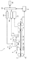
図1は、本発明の一形態に係るカラーフィルタの製造装置を示している。図1に示すように、製造装置1は、カラーフィルタの素材となるフィルム材2を搬送する搬送手段としてのローラ3a、3bと、インク噴射手段としてのインクジェット装置4と、撮像装置5と、光学的検出装置6と、を備えている。ローラ3a、3bはフィルム材2を挟んで保持しながら搬送することができる。フィルム材2は、ローラ3a、3bによって、矢印7方向に搬送される。ローラ3a、3bは、搬送コントローラ8によって搬送速度、方向、搬送の開始、停止等の動作が制御される。また、フィルム材2は、搬送経路に配置されたフィルム材ステージ9によって裏面側から支持されている。
FIG. 1 shows a color filter manufacturing apparatus according to an embodiment of the present invention. As shown in FIG. 1, a
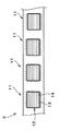
図2はフィルム材2の平面図である。フィルム材2には、長方形状の複数のフィルタ形成領域11が所定間隔を開けて並べられている。各フィルタ形成領域11には、基準パターン12が形成されている。この基準パターン12は、いわゆるブラックマトリクスパターンとして構成されている。基準パターン12には長方形状の枠13と枠13内に枠13の長辺に平行な換言すればフィルム材2の長手方向に平行な複数の水平パターン14とが設けられている。
FIG. 2 is a plan view of the
図3は図2のフィルム材2の拡大図である。フィルム材2の長手方向と直交する方向の一端側(図2の上側)には、複数のエンコーダタイミングマーク15が、搬送速度とインク噴射範囲とに応じた所定間隔を開けて並べられており、エンコーダタイミングマーク15間には、複数のカウンタマーク16が搬送速度に対応した所定間隔を開けて長手方向に並べられている。エンコーダタイミングマーク15とカウンタマーク16とは、いずれも長手方向と直交する方向に延びており、フィルタ形成領域11を避けるようにして設けられている。エンコーダタイミングマーク15はカウンタマーク16の倍程度の長さである。エンコーダタイミングマーク15及びカウンタマーク16の側方(図2の上側)には、複数のアライメントマーク19が撮像装置5による一度の撮像で複数撮像される程度の間隔を開けて長手方向に並べられている。これらのエンコーダタイミングマーク15、カウンタマーク16及びアライメントマーク19は、長手方向と直交する方向の他端側(図2の下側)にも長手方向と直交する方向の中心線に対して対照的な位置に設けられている。つまり、これらのマーク15、16、19はフィルタ形成領域11を避けるようにしてその両側に配置されている。これらのマーク15、16、19の各機能の詳細に関しては後述する。
FIG. 3 is an enlarged view of the
図1に示すように、インクジェット装置4は、ヘッド部20を有している。ヘッド部20の先端にはフィルム材2にインクを噴射するインクジェットノズル21が設けられている。ヘッド部20には、インクが貯蔵された不図示のタンクが接続されており、このタンクから汲み上げられたインクはヘッド部20に供給される。ヘッド部20はフィルム材2の表面側に配置されたステージ22に支持されている。ステージ22の詳細な構造の説明は省略するが、このステージ22は、フィルム材2と平行な平面内を、フィルム材2の長手方向と平行なX軸方向と、長手方向と垂直なY軸方向と、ヘッド部20の中央を中心とする回転方向とに移動可能に構成されている。ステージ22は、不図示の駆動装置によって駆動され、その駆動装置はステージコントローラ23によって動作制御される。また、ヘッド部20にはヘッド制御部24が接続されており、そのヘッド制御部24によってインクの噴射動作が制御される。
As shown in FIG. 1, the inkjet device 4 has a
撮像装置5は、フィルム材2の裏面側から光を照射する画像認識用照明28と、画像認識用照明28の照明により得られたフィルム材2の画像を所定方向へ反射させるダイクロックミラー30と、ダイクロックミラー30にて反射された画像を撮像するCCDカメラ31とを有している。CCDカメラ31は、フィルム材ステージ9の上方のダイクロックミラー30と同程度の高さに設けられており、CCDカメラ31が撮像した画像は画像処理部32に送られる。画像処理部32に送られた画像に対して所定の画像処理を行うことにより図3に示したアライメントマーク19が検出される。撮像装置5はインクジェット装置4とともにステージ22に支持されており、ステージ22の移動にともない画像認識用照明28、ダイクロックミラー30、CCDカメラ31も移動する。撮像装置5と、画像処理部32とが連携することによって撮像装置5と画像処理部32との組み合わせが本発明に係る位置検出手段として機能する。
The imaging device 5 includes an
光学的検出装置6は、図3に示したエンコーダタイミングマーク15及びカウンタマーク16を検出するための装置でありステージ22に支持されている。光学的検出装置6は、フィルム材ステージ9の下方に設けられたレーザ照射装置34と、フィルム材2の表面側に配置されてフィルム材2を透過したレーザ照射装置34からのレーザ光を受光するレーザ受光装置35とが組み合わされることにより構成されている。図3に示されたレーザスポットA、Bは、レーザ照射装置34によるレーザ光の照射位置である。レーザ照射装置34には、エンコーダタイミングマーク15のみに対してレーザ光を射出してレーザスポットAを形成する一組のレーザダイオードを備えるとともに、カウンタマーク16及びエンコーダタイミングマーク15に対してレーザ光を射出してレーザスポットBを形成するもう一組のレーザダイオードを備えている。レーザ受光装置35はレーザスポットA、Bからの各レーザ光を別々に受光できる二組のフォトダイオードを備えている。光学的検出装置6はステージ22に支持されているので、ステージ22の移動にともないレーザ照射装置34及びレーザ受光装置35も移動する。また、レーザ受光装置35がレーザスポットA、Bから検出したレーザ光の各光量は演算部36に送られる。
The
演算部36はレーザ受光装置35から送られた各レーザスポットA、Bの光量に基づいてフィルム材2に対するレーザ光の透過率を算出し、その透過率に基づいてエンコーダタイミングマーク15及びカウンタマーク16の検出を行う。図3に示すように、エンコーダタイミングマーク15はフィルム材2の長手方向と直交する方向の一端側と他端側とに中心線CLに対して対照的に設けられている。このため、長手方向に搬送されるフィルム材2が搬送方向とずれることなくまっすぐに搬送された場合には、長手方向と直交する方向の一端側のエンコーダタイミングマーク15と、これと対照的に設けられた他端側のエンコーダタイミングマーク15とは同時に検出される。これに対して、フィルム材2が搬送方向7に対して傾いた場合には、光学的検出装置6とエンコーダタイミングマーク15との位置関係がずれるので検出タイミングに差が生じる。従って、一端側及び他端側の各エンコーダタイミングマーク15が同時に検出されるように、ステージ22を移動させてインクジェット装置4の位置を制御することにより、フィルム材2の傾きに伴うインクの噴射位置のずれを補正することができる。エンコーダタイミングマーク15はこうした機能を持つため、長手方向と直交する方向の一端側に設けられたエンコーダタイミングマーク15と、これと対照的に長手方向と直交する方向の他端側に設けられたエンコーダタイミングマーク15とが、本発明に係る一対の検出部に相当し、これらが本発明に係るタイミング調整部として機能する。
The
また、カウンタマーク16及びそエンコーダタイミングマーク15が検出されると、演算部36で保持している累計カウント数がカウントアップされる。このため、カウンタマーク16及びエンコーダタイミングマーク15が本発明に係るカウント用マークとして機能し、演算部36が本発明に係る数値保持手段として機能する。そして、光学的検出装置6と、演算部36とが連携することによって光学的検出装置6と演算部36との組み合わせが本発明に係る検出手段として機能する。
When the
主制御部40は、搬送コントローラ8、ステージコントローラ23、ヘッド制御部24、画像処理部32、演算部36に接続され、それらの動作の制御を所定のプログラムに従って実行するコンピュータとして構成されている。図4は、主制御部40が実行するステージ22の位置制御ルーチンの一例を示すフローチャートである。
The
図4の制御ルーチンでは、ステップS1において搬送された状態のフィルム材2から光学的検出装置6が検出した光量に基づき、一対のエンコーダタイミングマーク15を検出するように演算部36に指示を出す。続くステップS2では、検出した一対のエンコーダタイミングマーク15から各エンコーダタイミングマーク15の検出タイミングが同一か否かを判定する。ステップS2の判定が肯定的判定の場合は、以降のステップをスキップして今回のルーチンを終了し、否定的判定の場合は、ステップS3に進む。ステップS3では、エンコーダタイミングマーク15毎の検出タイミングが同一となるようにステージ22の位置を調整して今回のルーチンを終了する。
In the control routine of FIG. 4, an instruction is issued to the
主制御部40が図4の制御ルーチンを実行することにより、搬送された状態のフィルム材2から一対のエンコーダタイミングマーク15が検出され、エンコーダタイミングマーク15毎の検出タイミングが同一となるようにヘッド部20の位置が調整される。
When the
図4の制御と並行して、主制御部40はインクジェット装置4によるインクの噴射制御を行っている。搬送された状態のフィルム材2から一対のエンコーダタイミングマーク15が検出された場合には、ヘッド部20のインクジェットノズル21からインクを噴射させるように主制御部40によってヘッド制御部24に指示が出される。エンコーダタイミングマーク15はフィルム材2の搬送速度とインク噴射範囲とに応じた所定間隔を開けて設けられているので、エンコーダタイミングマーク15の検出タイミングとインクの噴射タイミングとを予め関連付けておくことにより、ヘッド部20がインクを噴射する適切なタイミングを調整することができる。そして、このインク噴射タイミングの調整と、図4の制御ルーチンとは、どちらもフィルム材2を搬送しながら行われる。このため、フィルタ形成領域11が移動する度にフィルム材2の搬送を停止しなくてよいので、複数のフィルタ形成領域11が所定間隔を開けて長手方向に並べられたフィルム材2を使用して連続的にカラーフィルタの製造を行うことができる。主制御部40は、図4の制御ルーチンを実行するとともに、エンコーダタイミングマーク15に基づいてインクジェット装置4を制御することにより本発明に係る制御手段として機能する。
In parallel with the control of FIG. 4, the
図5は、主制御部40が実行するカウント制御ルーチンの一例を示すフローチャートである。図5の制御ルーチンでは、ステップS11において搬送された状態のフィルム材2から一対のカウンタマーク16及びエンコーダタイミングマーク15を検出するように演算部36に指示を出し、これらの検出にともなって演算部36で保有する累計カウント数をカウントアップする。ステップS12では、カウントアップ後の累計カウント数が所定値以上であるか否かを判定する。ステップS12の判定が否定的判定の場合には今回のルーチンを終了する。一方、ステップS12の判定が肯定的判定の場合には、ステップS13に進み累計カウント数をリセットして今回のルーチンを終了する。主制御部40は、図4及び図5のルーチンを所定の周期で繰り返し実行する。
FIG. 5 is a flowchart illustrating an example of a count control routine executed by the
主制御部40が図5のルーチンを実行することによってフィルム材2の搬送状態に応じて累計カウント数のカウントアップが行われる。これにより、カラーフィルタの製造装置1の稼働状況を把握することができる。また、適切な所定値にて累計カウント数のリセットが行われるため、カウント数の桁あふれを防止することができる。
When the
図4に示した位置制御は、フィルム材2の傾きに対応する制御であるが、図4の制御と並行して、図3に示したアライメントマーク19に基づいて上述したY軸方向に関するステージ22の位置制御も行っている。即ち、主制御部40は、搬送中のフィルム材からアライメントマーク19を検出し、検出されたアライメントマーク19がY軸方向の所定位置にあるか否かを判定する。アライメントマーク19の検出はCCDカメラ31を用いて行われる。この判定が否定的判定の場合にはアライメントマーク19が所定位置となるようにステージ22の位置を調整する。これにより、フィルム材2に生じた搬送方向と直交する方向のずれに対応してヘッド部20の位置を調整することができる。
The position control shown in FIG. 4 is a control corresponding to the inclination of the
本発明は、上記の形態に限定されず、本発明の要旨の範囲内で種々の形態にて実施できる。上記の形態では、一対のエンコーダタイミングマークがフィルム材の長手方向と直交する直線上に位置しているが、これに限定されるものではなく、長手方向と交差する直線上に位置する一対のエンコーダタイミングマークが設けられていればよい。このため、一対のエンコーダタイミングマークはフィルタ形成領域を挟んで設けられていなくてもよく、例えば、フィルタ形成領域間に設けられてもよい。また、エンコーダタイミングマークは長手方向と直交する方向に延びる直線状に形成されているが、この形状に限定されるものではなく、光学的検出装置で検出できる限りにおいていかなる形状でもよい。カウンタマークは省略してもよいし、エンコーダタイミングマークをカウンタマークとして兼用してもよい。 The present invention is not limited to the above-described embodiment, and can be implemented in various forms within the scope of the gist of the present invention. In the above embodiment, the pair of encoder timing marks are located on a straight line orthogonal to the longitudinal direction of the film material, but the present invention is not limited to this, and a pair of encoders located on a straight line intersecting the longitudinal direction A timing mark may be provided. For this reason, the pair of encoder timing marks may not be provided with the filter formation region interposed therebetween, and may be provided, for example, between the filter formation regions. The encoder timing mark is formed in a straight line extending in a direction orthogonal to the longitudinal direction, but is not limited to this shape, and may be any shape as long as it can be detected by an optical detection device. The counter mark may be omitted, or the encoder timing mark may be used as the counter mark.
また、アライメントマークは、Y軸方向の位置調整ができる限りにおいてどのような形状であってもよい。またアライメントマークを設ける位置にも制限はない。また、アライメントマークは搬送方向に対して所定間隔を開けて複数個設けられることは一例にすぎない。従って、アライメントマークをフィルタ形成領域の側方において、長手方向に連続的に延びる直線状にすることもできる。 Further, the alignment mark may have any shape as long as the position adjustment in the Y-axis direction can be performed. There is no restriction on the position where the alignment mark is provided. In addition, it is merely an example that a plurality of alignment marks are provided at predetermined intervals with respect to the transport direction. Therefore, the alignment marks can be linearly extending continuously in the longitudinal direction on the side of the filter forming region.
また、検出手段としての光学的検出装置6は、エンコーダタイミグマーク及びカウンタマークを検出できる限りにおいて、種々の構成を採用することができる。また、上記形態では、位置検出手段としての撮像手段6及び画像処理部32と、検出手段としての光学的検出装置6とを別々に設けているが、位置検出手段としての撮像手段6及び画像処理部32を検出手段として兼用してもよい。
Further, the
1 カラーフィルタの製造装置
2 フィルム材
3a、3b ローラ(搬送手段)
4 インクジェット装置(インク噴射手段)
5 光学的検出装置
6 撮像装置
11 フィルタ形成領域
15 エンコーダタイミングマーク(検出部)
32 画像処理部
36 演算部
40 主制御部(制御手段)
DESCRIPTION OF
4 Inkjet device (ink ejecting means)
DESCRIPTION OF SYMBOLS 5
32
Claims (4)
前記フィルタ形成領域にインクを噴射して塗布するインク噴射手段と、
前記搬送手段にて搬送された状態の前記フィルム材から前記一対の検出部を検出する検出手段と、
前記検出手段が検出した前記検出部毎の検出タイミングに基づいて搬送方向に対する前記フィルム材の傾きに伴うインクの噴射位置のずれが補正されるように前記インク噴射手段の位置を制御し、かつ、前記検出手段が検出した前記一対の検出部に基づいて前記フィルタ形成領域にインクが噴射されるように前記インク噴射手段の動作を制御する制御手段と、を備えることを特徴とするカラーフィルタの製造装置。 A film material in which a plurality of filter formation regions are arranged in the longitudinal direction at predetermined intervals, and a timing adjustment unit having a pair of detection units located on a straight line intersecting the longitudinal direction is provided so as to avoid the filter formation region Transport means for transporting along the longitudinal direction;
Ink ejecting means for ejecting and applying ink to the filter forming region;
Detecting means for detecting the pair of detection units from the film material in a state of being conveyed by the conveying means;
Controlling the position of the ink ejecting means so that the deviation of the ink ejecting position due to the inclination of the film material with respect to the transport direction is corrected based on the detection timing of each detection unit detected by the detecting means; and And a control means for controlling the operation of the ink ejecting means so that the ink is ejected to the filter forming region based on the pair of detecting portions detected by the detecting means. apparatus.
前記制御手段は、前記検出部毎の検出タイミングが同一となるように前記インク噴射手段の位置を制御する請求項1に記載のカラーフィルタの製造装置。 The pair of detection units are located on a straight line orthogonal to the longitudinal direction of the film material,
The color filter manufacturing apparatus according to claim 1, wherein the control unit controls the position of the ink ejecting unit such that the detection timings of the detection units are the same.
前記カウント用マークの累計カウント数を保持する数値保持手段を更に備え、
前記検出手段は、搬送された状態の前記フィルム材から前記カウント用マークを検出し、
前記制御手段は、前記検出手段が検出した前記カウント用マークに基づいて前記数値保持手段が保持する前記累計カウント数のカウントアップ及び所定値における前記累計カウント数のリセットの少なくともいずれか一方を実行する請求項1又は2に記載のカラーフィルタの製造装置。 The film material is provided with a count mark on the side of the filter formation region,
Further comprising a numerical value holding means for holding the cumulative count number of the counting mark,
The detection means detects the mark for counting from the film material in a conveyed state,
The control means executes at least one of counting up the cumulative count number held by the numerical value holding means and resetting the cumulative count number at a predetermined value based on the count mark detected by the detection means. The color filter manufacturing apparatus according to claim 1 or 2.
前記搬送手段にて搬送された状態の前記フィルム材から前記アライメントマークを検出する位置検出手段を更に備え、
前記制御手段は、前記位置検出手段が検出した前記アライメントマークに基づいて前記インク噴射手段の位置を制御する請求項1〜3に記載のカラーフィルタの製造装置。 The film material is provided with an alignment mark on the side of the filter formation region for adjusting the deviation in the direction orthogonal to the transport direction,
Further comprising position detection means for detecting the alignment mark from the film material in a state of being conveyed by the conveyance means;
The color filter manufacturing apparatus according to claim 1, wherein the control unit controls the position of the ink ejecting unit based on the alignment mark detected by the position detecting unit.
Priority Applications (1)
| Application Number | Priority Date | Filing Date | Title |
|---|---|---|---|
| JP2008239388A JP5088280B2 (en) | 2008-09-18 | 2008-09-18 | Color filter manufacturing equipment |
Applications Claiming Priority (1)
| Application Number | Priority Date | Filing Date | Title |
|---|---|---|---|
| JP2008239388A JP5088280B2 (en) | 2008-09-18 | 2008-09-18 | Color filter manufacturing equipment |
Publications (2)
| Publication Number | Publication Date |
|---|---|
| JP2010072317A true JP2010072317A (en) | 2010-04-02 |
| JP5088280B2 JP5088280B2 (en) | 2012-12-05 |
Family
ID=42204155
Family Applications (1)
| Application Number | Title | Priority Date | Filing Date |
|---|---|---|---|
| JP2008239388A Expired - Fee Related JP5088280B2 (en) | 2008-09-18 | 2008-09-18 | Color filter manufacturing equipment |
Country Status (1)
| Country | Link |
|---|---|
| JP (1) | JP5088280B2 (en) |
Citations (5)
| Publication number | Priority date | Publication date | Assignee | Title |
|---|---|---|---|---|
| JP2002107529A (en) * | 2000-09-29 | 2002-04-10 | Dainippon Printing Co Ltd | Method for producing member for color filter |
| JP2004337727A (en) * | 2003-05-14 | 2004-12-02 | Seiko Epson Corp | Droplet discharging apparatus, electro-optical device production method, electro-optical device, electronic device, and substrate |
| JP2004337702A (en) * | 2003-05-14 | 2004-12-02 | Seiko Epson Corp | Apparatus and method for discharging droplet |
| JP2006159117A (en) * | 2004-12-08 | 2006-06-22 | Seiko Epson Corp | Method of correcting head position, apparatus for correcting head position, droplet discharge apparatus, method of manufacturing electro-ptical device, electro-optical device and electronic equipment |
| JP2007152215A (en) * | 2005-12-05 | 2007-06-21 | Dainippon Printing Co Ltd | Pattern forming apparatus and pattern forming method |
-
2008
- 2008-09-18 JP JP2008239388A patent/JP5088280B2/en not_active Expired - Fee Related
Patent Citations (5)
| Publication number | Priority date | Publication date | Assignee | Title |
|---|---|---|---|---|
| JP2002107529A (en) * | 2000-09-29 | 2002-04-10 | Dainippon Printing Co Ltd | Method for producing member for color filter |
| JP2004337727A (en) * | 2003-05-14 | 2004-12-02 | Seiko Epson Corp | Droplet discharging apparatus, electro-optical device production method, electro-optical device, electronic device, and substrate |
| JP2004337702A (en) * | 2003-05-14 | 2004-12-02 | Seiko Epson Corp | Apparatus and method for discharging droplet |
| JP2006159117A (en) * | 2004-12-08 | 2006-06-22 | Seiko Epson Corp | Method of correcting head position, apparatus for correcting head position, droplet discharge apparatus, method of manufacturing electro-ptical device, electro-optical device and electronic equipment |
| JP2007152215A (en) * | 2005-12-05 | 2007-06-21 | Dainippon Printing Co Ltd | Pattern forming apparatus and pattern forming method |
Also Published As
| Publication number | Publication date |
|---|---|
| JP5088280B2 (en) | 2012-12-05 |
Similar Documents
| Publication | Publication Date | Title |
|---|---|---|
| US9050829B2 (en) | Medium transportation device and recording apparatus | |
| CN107000429B (en) | Tablet printing equipment and tablet printing process | |
| TWI750339B (en) | Droplet ejection device, droplet ejection method and computer memory medium | |
| WO2015166776A1 (en) | Electronic component mounting apparatus | |
| US9025196B2 (en) | Printing system and printing method | |
| KR102000887B1 (en) | Tablet printing device and tablet printing method | |
| KR101986894B1 (en) | Droplet ejection apparatus and droplet ejection condition correction method | |
| JP2020111037A (en) | Liquid discharge device, and method for correcting deviation of impact position of liquid | |
| JP5593740B2 (en) | Inkjet recording device | |
| JP5948799B2 (en) | Medium transport apparatus, recording apparatus, and medium transport control method | |
| US20180272746A1 (en) | Liquid droplet discharging apparatus, and pattern reading method of liquid droplet discharging apparatus | |
| JP2007015194A (en) | Maintenance method of recording head and inkjet printer | |
| JP5088280B2 (en) | Color filter manufacturing equipment | |
| JP6079683B2 (en) | Electronics | |
| JP2007015193A (en) | Maintenance method of full line head and inkjet printer | |
| JP2017185694A (en) | Recording device and calculation method for amount of movement of conveyance belt | |
| US10434799B2 (en) | Systems and methods for reducing banding artefacts of an image on a substrate | |
| JP6711129B2 (en) | Liquid ejection device and liquid ejection method | |
| KR20210060093A (en) | Nozzle failure detection apparatus and method of multi-pass digital textile printing head | |
| JP5606258B2 (en) | Coating method and coating apparatus | |
| JP2014024352A5 (en) | Recording device | |
| JP2011245779A (en) | Liquid droplet discharging device | |
| JP2007326328A (en) | Inkjet recording method and inkjet recording system | |
| JP2013216033A (en) | Image forming apparatus | |
| JP4483316B2 (en) | Inkjet recording apparatus and optical path detection method |
Legal Events
| Date | Code | Title | Description |
|---|---|---|---|
| A621 | Written request for application examination |
Free format text: JAPANESE INTERMEDIATE CODE: A621 Effective date: 20110616 |
|
| A977 | Report on retrieval |
Free format text: JAPANESE INTERMEDIATE CODE: A971007 Effective date: 20120524 |
|
| A131 | Notification of reasons for refusal |
Free format text: JAPANESE INTERMEDIATE CODE: A131 Effective date: 20120529 |
|
| A521 | Written amendment |
Free format text: JAPANESE INTERMEDIATE CODE: A523 Effective date: 20120719 |
|
| TRDD | Decision of grant or rejection written | ||
| A01 | Written decision to grant a patent or to grant a registration (utility model) |
Free format text: JAPANESE INTERMEDIATE CODE: A01 Effective date: 20120814 |
|
| A01 | Written decision to grant a patent or to grant a registration (utility model) |
Free format text: JAPANESE INTERMEDIATE CODE: A01 |
|
| A61 | First payment of annual fees (during grant procedure) |
Free format text: JAPANESE INTERMEDIATE CODE: A61 Effective date: 20120827 |
|
| FPAY | Renewal fee payment (event date is renewal date of database) |
Free format text: PAYMENT UNTIL: 20150921 Year of fee payment: 3 |
|
| R150 | Certificate of patent or registration of utility model |
Free format text: JAPANESE INTERMEDIATE CODE: R150 |
|
| LAPS | Cancellation because of no payment of annual fees |