JP2010072196A - Fixing structure, optical scanner, image forming apparatus and fixing method - Google Patents
Fixing structure, optical scanner, image forming apparatus and fixing method Download PDFInfo
- Publication number
- JP2010072196A JP2010072196A JP2008237896A JP2008237896A JP2010072196A JP 2010072196 A JP2010072196 A JP 2010072196A JP 2008237896 A JP2008237896 A JP 2008237896A JP 2008237896 A JP2008237896 A JP 2008237896A JP 2010072196 A JP2010072196 A JP 2010072196A
- Authority
- JP
- Japan
- Prior art keywords
- adhesive
- main surface
- fixing structure
- housing
- fixing
- Prior art date
- Legal status (The legal status is an assumption and is not a legal conclusion. Google has not performed a legal analysis and makes no representation as to the accuracy of the status listed.)
- Granted
Links
Images


Landscapes
- Laser Beam Printer (AREA)
- Mounting And Adjusting Of Optical Elements (AREA)
- Mechanical Optical Scanning Systems (AREA)
- Facsimile Scanning Arrangements (AREA)
Abstract
Description
本発明は、固定構造、光走査装置、画像形成装置及び固定方法に関し、より特定的には、光学素子とハウジングとを接着剤にて固定する固定構造、光走査装置、画像形成装置及び固定方法に関する。 The present invention relates to a fixing structure, an optical scanning device, an image forming apparatus, and a fixing method, and more specifically, a fixing structure, an optical scanning device, an image forming apparatus, and a fixing method for fixing an optical element and a housing with an adhesive. About.
画像形成装置の光走査装置内には、ミラーやレンズ等の光学素子が設けられている。このような光走査装置では、一般的に、光学素子を板ばねにより光走査装置のハウジングに対して固定する固定構造が用いられている。 An optical element such as a mirror or a lens is provided in the optical scanning device of the image forming apparatus. In such an optical scanning device, generally, a fixing structure for fixing an optical element to a housing of the optical scanning device by a leaf spring is used.
しかしながら、上記従来の固定構造では、光学素子の固定のために板ばねが必要となり、部品点数が増加するという問題がある。そこで、近年では、光学素子を接着剤によりハウジングに固定する固定構造が提案されている。図19は、光学素子を接着剤によりハウジングに固定した固定構造を示した断面構造図である。 However, the conventional fixing structure requires a leaf spring for fixing the optical element, which increases the number of parts. Therefore, in recent years, a fixing structure for fixing the optical element to the housing with an adhesive has been proposed. FIG. 19 is a cross-sectional structure diagram illustrating a fixing structure in which an optical element is fixed to a housing with an adhesive.
図19には、ハウジング102、光学素子104及び接着剤110が示されている。ハウジング102は、光学素子104を位置決めした状態で搭載させるための突起108を備えている。接着剤110は、突起108の周囲に塗布され、ハウジング102と光学素子104とを固定している。このように、接着剤110が用いられることにより、板ばね106が不要となり、固定構造の部品点数が削減される。
FIG. 19 shows the
しかしながら、図19に示す固定構造では、画像形成装置の使用時に、接着剤110が、ハウジング102又は光学素子104から剥離するおそれがある。より詳細には、ハウジング102と光学素子104とは、異なる材料により作製されているので、異なる線膨張係数を有している。そのため、画像形成装置の使用時に温度変化が生じると、ハウジング102の伸びと光学素子104の伸びとの間に差が生じる。その結果、突起108及び接着剤110の両端が引っ張られる方向に応力が発生し、突起108及び接着剤110が該応力により変形する。このように、突起108及び接着剤110が変形することにより、ハウジング102の伸びと光学素子104の伸びと差が吸収される。
However, in the fixing structure illustrated in FIG. 19, the
ところで、接着剤110は、突起108の周囲に塗布されている。また、突起108は、ハウジング102と同じ材料により作製されているので、接着剤110よりも大きなヤング率を有している。故に、突起108は、接着剤110に比べて応力によって変形しにくい。そのため、前記のように、突起108及び接着剤110に応力が発生すると、接着剤110は、突起108が存在するために、ハウジング102の伸びと光学素子104の伸びとの差を吸収できる程度に十分に変形することができない。その結果、接着剤110とハウジング102との境界部分及び接着剤110と光学素子104との境界部分に、応力が集中してしまい、接着剤110が、ハウジング102又は光学素子104から剥離してしまう。
Incidentally, the
このような問題に対する固定構造として、例えば、特許文献1に記載の光走査装置が提案されている。図20は、特許文献1に記載の光学装置を示した断面構造図である。図20では、ハウジング102、光学素子104及び接着剤110が記載されている。
As a fixed structure for such a problem, for example, an optical scanning device described in
図20に示す光走査装置では、ハウジング102は、その主面から突出する2種類の台座116,118を有している。台座116は、光学素子104を位置決めするためのものであり、光学素子104の長手方向の両端近傍に接触している。台座118は、その上面に接着剤110が塗布され、光学素子104の長手方向の中央近傍を該接着剤110により固定している。すなわち、該光走査装置では、位置決めのための台座116と固定のための台座118とは、離れた位置に設けられている。
In the optical scanning device shown in FIG. 20, the
しかしながら、図20に示す光走査装置では、接着剤110は、台座118の上面に薄膜状に塗布されているだけであり、十分な高さを有していない。故に、接着剤110は、ハウジング102の伸びと光学素子104の伸びとの差を吸収できる程度に変形できない。そのため、図20に示す光走査装置においても、接着剤110が、ハウジング102又は光学素子104から剥がれるおそれがある。
そこで、本発明の目的は、接着剤がハウジング又は光学素子から剥がれることを抑制できる固定構造、光走査装置、画像形成装置及び固定方法を提供することである。 Accordingly, an object of the present invention is to provide a fixing structure, an optical scanning device, an image forming apparatus, and a fixing method capable of suppressing the adhesive from being peeled off from the housing or the optical element.
本発明の一形態に係る固定構造は、第1の主面を有する光学素子と、前記第1の主面と隙間をあけた状態で対向している第2の主面を有しているハウジングと、前記第1の主面又は該第2の主面の何れか一方から突出して、該第1の主面又は該第2の主面の他方に接触することにより、前記ハウジングと前記光学素子とを位置決めする第1の突起と、前記第1の突起から離れた位置において、前記第1の主面と前記第2の主面とを繋ぐように設けられている接着剤と、を備えていることを特徴とする。 A fixing structure according to an aspect of the present invention includes an optical element having a first main surface and a housing having a second main surface facing the first main surface with a gap therebetween. The housing and the optical element by projecting from either the first main surface or the second main surface and contacting the other of the first main surface or the second main surface And an adhesive provided to connect the first main surface and the second main surface at a position away from the first protrusion. It is characterized by being.
前記固定構造は、光走査装置に適用することができる。 The fixing structure can be applied to an optical scanning device.
前記光走査装置は、画像形成装置に適用することができる。 The optical scanning device can be applied to an image forming apparatus.
本発明の一形態に係る固定方法は、第1の主面を有している光学素子と第2の主面を有しているハウジングとを固定する固定方法であって、前記第1の主面又は前記第2の主面の少なくともいずれか一方に接着剤を塗布する工程と、前記第1の主面又は前記第2の主面のいずれか一方に設けられた突起に該第1の主面又は該第2の主面のいずれか他方を接触させて、前記光学素子と前記ハウジングとの位置合わせを行う工程と、前記第1の主面と前記第2の主面とを近接させて、該第1の主面と該第2の主面とを繋ぐように前記接着剤を変形させる工程と、前記接着剤を硬化させる工程と、を備えていること、を特徴とする。 A fixing method according to an aspect of the present invention is a fixing method for fixing an optical element having a first main surface and a housing having a second main surface, wherein the first main surface is fixed. A step of applying an adhesive to at least one of the first main surface and the second main surface, and a protrusion provided on either the first main surface or the second main surface. A step of bringing the optical element and the housing into alignment by bringing one of the surface and the second main surface into contact with each other, and bringing the first main surface and the second main surface close to each other And a step of deforming the adhesive so as to connect the first main surface and the second main surface, and a step of curing the adhesive.
以下、本発明の一実施形態に係る固定構造、光走査装置、画像形成装置及び固定方法について、図面を参照しながら説明する。 Hereinafter, a fixing structure, an optical scanning device, an image forming apparatus, and a fixing method according to an embodiment of the present invention will be described with reference to the drawings.
(全体構成)
図1は、本発明の一実施形態に係る画像形成装置の概略構成図である。図2は、本発明の一実施形態に係る光走査装置の概略斜視図である。図2に示す光走査装置1は、概略、光源ユニット2、ポリゴンミラー3、走査レンズ4a,4b、折り返しミラー5及びハウジング10により構成されており、図1の画像形成装置50に搭載されている。
(overall structure)
FIG. 1 is a schematic configuration diagram of an image forming apparatus according to an embodiment of the present invention. FIG. 2 is a schematic perspective view of an optical scanning device according to an embodiment of the present invention. The
画像形成装置50は、いわゆる4サイクル方式のカラープリンタであり、感光体ドラム40の周囲に、帯電器52、光走査装置1、YMCKの4色のトナーを内蔵したロータリ式の現像器53、中間転写ベルト54などを配置した周知のものである。光走査装置1によって感光体ドラム40上にYMCKの静電潜像が順次形成され、該静電潜像は現像器53で所定の色に現像され、中間転写ベルト54に順次1次転写されて合成される。合成されたトナー像は、給紙部55から1枚ずつ給紙される用紙上に、2次転写ローラ56から付与される電界によって2次転写される。続いて、この用紙は、定着器57でトナー像の加熱定着を施され、プリンタ本体の上面に排出される。
The
光源ユニット2から放射されたビームは、主走査方向Yにほぼ平行な光に整形されており、ポリゴンミラー3に入射する。ポリゴンミラー3に入射したビームは、主走査方向Yに等角速度に偏向され、走査レンズ4a,4bを透過することで収差を補正され、折り返しミラー5にて反射して感光体ドラム40上で結像する。感光体ドラム40は所定速度で回転駆動され、ビームによる主走査と感光体ドラム40の回転による副走査にて2次元の画像(静電潜像)が形成される。
The beam emitted from the
(固定構造)
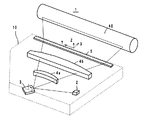
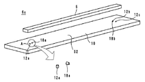
次に、折り返しミラー5のハウジング10に対する固定構造について図面を参照しながら説明する。図3は、固定構造6aの外観斜視図である。図4は、固定構造6aの断面構造図である。図3は、折り返しミラー5が固定される前の状態を示している。また、図3には、左端近傍の領域Aの拡大図が示されている。図4は、図3の固定構造6aの左端近傍を示している。以下では、ハウジング10の法線方向を単に法線方向と呼び、折り返しミラー5の長手方向を単に長手方向と呼ぶ。
(Fixed structure)
Next, a structure for fixing the
固定構造6aは、図3及び図4に示すように、折り返しミラー5、ハウジング10、突起12a〜12c及び接着剤14により構成されている(図3では接着剤14は図示せず。図4では、突起12b,12cは図示せず。)。折り返しミラー5は、ビームを反射する光学素子であり、長手方向を有する構造をなしている。また、折り返しミラー5は、図4に示すように、法線方向の下側に向く主面S1を有している。折り返しミラー5は、例えば、光学ガラスや光学樹脂(ゼオネックス330R)により作製される。
3 and 4, the fixing structure 6a includes the
ハウジング10は、図3及び図4に示すように、法線方向の上側を向く主面S2を有している。突起12a〜12cは、主面S2から法線方向に突出している円柱であり、図4に示すように、その上面にて折り返しミラー5の主面S1と接触することにより、折り返しミラー5とハウジング10とを位置決めする役割を果たす。また、突起12a〜12cは、ハウジング10と一体的に構成されている。突起12aは、折り返しミラー5の長手方向の左端近傍にて、主面S1と接触するように設けられている。また、突起12b,12cは、折り返しミラー5の長手方向の右端近傍にて、主面S2と接触するように設けられている。ハウジング10は、例えば、樹脂(マルチロンDN−1525又はザイロン)又はアルミニウムにより作製される。
As shown in FIGS. 3 and 4, the
折り返しミラー5は、主面S1と主面S2とが隙間をあけた状態で対向するようにハウジング10上に搭載される。接着剤14は、図4に示すように、突起12a〜12c(図4では、突起12aのみ記載)から離れた位置において、主面S1と主面S2とを繋ぐように設けられた柱状の光硬化樹脂である。該接着剤14は、長手方向における折り返しミラー5の中点よりも、長手方向における折り返しミラー5の端部に近い位置に設けられている。
The
また、接着剤14は、突起12a〜12cのヤング率よりも小さなヤング率を有している。すなわち、接着剤14は、突起12a〜12cに比べて応力により変形し易い材料により作製されている。また、接着剤14は、硬化時に発生する応力を緩和することを考えるとガラス転移点(Tg)は低いことが望ましい。一方、常温での使用を考えると、ガラス転移点(Tg)は60℃程度あるいはそれ以上が望ましい。更に、過酷環境試験を実施した場合、ガラス転移点(Tg)があまりにも高いと、剥がれの原因になる。よって、ガラス転移点が110℃以下の樹脂であることが好ましい。以上のような条件を満たす接着剤としては、例えば、UVZ−108Eやワールドロックなどが挙げられる。以下に示す表1は、折り返しミラー5、ハウジング10及び接着剤14に用いられ得る材料の物性を示した表である。
Moreover, the adhesive 14 has a Young's modulus smaller than the Young's modulus of the

なお、接着剤14は、主面S1と主面S2との間を繋ぐように設けられており、所謂、空中接着を行っている。空中接着では、折り返しミラー5とハウジング10とを固定すると共に、折り返しミラー5とハウジング10との間のスペーサーとして機能している。一般的な接着剤は、薄膜上に塗布して用いられるように設計されているので、空中接着は、一般的な接着剤の用いられ方とは異なる。そこで、接着剤14としては、接着性を有する樹脂材料の中から、以下の条件を満たすものを用いるようにすればよい。
The adhesive 14 is provided so as to connect the main surface S1 and the main surface S2, and performs so-called air bonding. In the aerial bonding, the
(1)折り返しミラー5及びハウジング10の両方に親和性があること。
(2)折り返しミラー5の伸びとハウジング10の伸びとの差を吸収できる線膨張係数を有すること。
(3)未硬化状態であっても、主面S1と主面S2との間で柱状を維持できる粘度を有していること。
(4)不可逆変形が小さいこと。
(1) Both the
(2) It has a linear expansion coefficient that can absorb the difference between the extension of the
(3) Even if it is an uncured state, it has the viscosity which can maintain columnar shape between main surface S1 and main surface S2.
(4) The irreversible deformation is small.
(効果)
以上のように構成された固定構造6aによれば、以下に説明するように、画像形成装置50内の温度が変化したとしても、接着剤14が折り返しミラー5又はハウジング10から剥がれることを抑制できる。より詳細には、表1に示すように、折り返しミラー5とハウジング10とは、異なる材料により作製されているので、異なる線膨張係数を有している。そのため、画像形成装置50内の温度が変化すると、折り返しミラー5の伸びとハウジング10の伸びとの間に差が生じる。このような伸びの差が発生すると、折り返しミラー5は、長手方向の中央部分が法線方向の上方向又は下方向に突出するように湾曲しようとする。そのため、主面S1と主面S2とを繋いでいる接着剤14は、その両端が引っ張られる応力を受ける。
(effect)
According to the fixing structure 6a configured as described above, it is possible to suppress the adhesive 14 from being peeled off from the
ここで、接着剤14は、突起12a〜12cから離れた位置に設けられている。よって、接着剤14は、図19に示した接着剤110と異なり、突起12a〜12cによる規制を受けることなく伸びることができる。更に、接着剤14は、主面S1と主面S2とを繋ぐように形成されているので、図20に示した接着剤110と異なり、法線方向において十分な長さを有している。よって、接着剤14は、両端が引っ張られる応力を受けた際に、図20に示した接着剤110と異なり大きく伸びることができる。したがって、接着剤14は、折り返しミラー5の伸びとハウジング10の伸びとの差を十分に吸収できる程度に伸びることができる。その結果、本実施形態に係る固定構造6aによれば、画像形成装置50内の温度が変化したとしても、接着剤14が折り返しミラー5又はハウジング10から剥がれることを抑制できる。
Here, the adhesive 14 is provided at a position away from the
また、本実施形態に係る固定構造6aによれば、接着剤14は、主面S1と主面S2とを繋ぐように設けられることにより、大きく伸びることができるので、以下に説明するように、より強固に折り返しミラー5をハウジング10に固定することができる。より詳細には、図20に示した光走査装置では、光学素子104の長手方向の中央近傍がハウジング102に対して固定されている。そのため、該光走査装置では、光学素子104の長手方向の両端部分に力が加わると、光学素子104がハウジング102から容易に外れてしまう。よって、光学素子104は、長手方向の両端に近い位置においてハウジング102に固定されていることが望ましい。
In addition, according to the fixing structure 6a according to the present embodiment, the adhesive 14 can be greatly extended by being provided so as to connect the main surface S1 and the main surface S2, so as described below, The
しかしながら、図20に示す光走査装置では、接着剤110が薄膜状に塗布されているので、接着剤110は、高さ方向に十分に伸びることができない。光学素子104の長手方向の両端近傍におけるハウジング102の伸びと光学素子104の伸びとの差は、光学素子104の長手方向の中央近傍におけるハウジング102の伸びと光学素子104の伸びとの差より大きいので、接着剤110は、光学素子104の長手方向の両端近傍に設けられると、ハウジング102又は光学素子104から剥がれてしまうおそれがある。
However, in the optical scanning device shown in FIG. 20, since the adhesive 110 is applied in a thin film shape, the adhesive 110 cannot sufficiently extend in the height direction. The difference between the extension of the
これに対して、図3及び図4に示す固定構造6aでは、接着剤14は、主面S1と主面S2とを繋ぐように設けられているので、法線方向において十分な高さを有している。そのため、接着剤14は、法線方向に十分に伸びることができるので、図20に示した接着剤110と異なり、折り返しミラー5の長手方向の両端近傍に位置させることが可能となる。このように、折り返しミラー5の長手方向の両端近傍を接着剤14によりハウジング10に固定することにより、折り返しミラー5の長手方向の両端に力が加わったとしても、図20に示す光学素子104のようにハウジング10から容易に外れることがなくなる。
In contrast, in the fixing structure 6a shown in FIGS. 3 and 4, the adhesive 14 is provided so as to connect the main surface S1 and the main surface S2, and therefore has a sufficient height in the normal direction. is doing. Therefore, since the adhesive 14 can extend sufficiently in the normal direction, unlike the adhesive 110 shown in FIG. 20, the adhesive 14 can be positioned near both ends in the longitudinal direction of the
また、接着剤14として、ガラス転移点が110℃以下の樹脂が用いられることにより、接着剤14が剥離・脱落を生じることなく、かつ、環境の変化あるいは経年変化により生じる折り返しミラー5と突起12a〜12cとの間の位置ずれを抑制できる。
Further, since a resin having a glass transition point of 110 ° C. or lower is used as the adhesive 14, the
(固定方法)
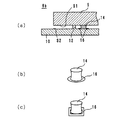
次に、図3及び図4に示す固定構造6aにより、折り返しミラー5を固定する固定方法について図面を参照しながら説明する。図5は、該固定方法の工程断面図である。図5では、図4と同様に、折り返しミラー5の長手方向の左端近傍を拡大して示した。
(Fixing method)
Next, a fixing method for fixing the
まず、図5(a)に示すように、ハウジング10の主面S2上に未硬化状態の接着剤14を塗布する。該未硬化状態の接着剤14は、25℃における粘度が6000mPa・s以上30000mPa・s以下の樹脂であることが好ましい。更に、該接着剤14は、UV照射により硬化する光硬化樹脂であることが好ましい。
First, as shown in FIG. 5A, an
次に、図5(b)に示すように、折り返しミラー5を主面S2に対して少し傾けることにより、主面S1と主面S2とを近接させて、主面S1を接着剤14に接触させる。これにより、接着剤14が、主面S1と主面S2とを繋ぐように柱状に変形する。
Next, as shown in FIG. 5B, the
次に、図4に示すように、主面S1に突起12a〜12c(図4では、突起12aのみ記載)を接触させて、折り返しミラー5とハウジング10との位置合わせを行う。このとき、接着剤14の法線方向の高さは、0.2mm以上1mm以下であることが好ましい。
Next, as shown in FIG. 4, the
最後に、接着剤14に対してUVを照射して、該接着剤14を硬化させる。これにより、折り返しミラー5がハウジング10に固定される。
Finally, the adhesive 14 is irradiated with UV to cure the adhesive 14. Thereby, the
以上のような固定方法によれば、図3及び図4に示した固定構造6aを得ることができる。また、該固定方法では、接着剤14に光硬化樹脂が用いられているので、接着剤14を硬化させることなく、図5(a)に示す接着剤14の塗布から図4に示す折り返しミラー5の位置合わせまでの工程を行うことができる。よって、固定構造6aの組立の効率が向上する。
According to the fixing method as described above, the fixing structure 6a shown in FIGS. 3 and 4 can be obtained. Further, in the fixing method, since a photo-curing resin is used for the adhesive 14, the
また、前記固定方法では、未硬化状態の接着剤14が、25℃における粘度が6000mPa・s以上30000mPa・s以下の樹脂であり、かつ、接着剤14の法線方向の高さが、0.2mm以上1mm以下である。そのため、接着剤14は、図4に示す折り返しミラー5の位置合わせの工程において、図4に示すような柱状から変形しにくい。
In the fixing method, the
(第1の変形例)
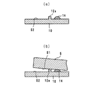
以下に、固定構造6aの第1の変形例に係る固定構造6bについて図面を参照しながら説明する。図6(a)は、固定構造6bの断面構造図である。図6(b)及び図6(c)は、接着剤14近傍の斜視図である。図6は、図3の固定構造6bの左端近傍を示している。
(First modification)
Hereinafter, a fixing structure 6b according to a first modification of the fixing structure 6a will be described with reference to the drawings. FIG. 6A is a cross-sectional structure diagram of the fixing structure 6b. 6B and 6C are perspective views of the vicinity of the adhesive 14. FIG. 6 shows the vicinity of the left end of the fixing structure 6b of FIG.
図6(a)及び図6(b)に示すように、固定構造6bにおいて、接着剤14が設けられている部分を囲むように、該接着剤14に対する濡れ性が主面S2よりも低い領域16が設けられていてもよい。このように領域16が設けられることにより、未硬化状態の接着剤14は、主面S2上に広がることなく、法線方向に十分な高さを有する球状をなすようになる。その結果、図5(b)に示した工程において、主面S1を接着剤14に接触させることが容易となる。よって、固定構造6bを容易に形成することが可能となる。
As shown in FIG. 6A and FIG. 6B, in the fixing structure 6b, a region where the wettability with respect to the adhesive 14 is lower than that of the main surface S2 so as to surround the portion where the adhesive 14 is provided. 16 may be provided. By providing the
なお、領域16は、図6(b)のように円形を有していてもよいし、図6(c)のように矩形状を有していてもよい。また、領域16は、主面S2に表面処理を施して形成されてもよいし、接着剤14に対する濡れ性が主面S2に対する濡れ性よりも低い材料を主面S2に塗布又は貼り付けることによって形成されてもよい。
Note that the
(第2の変形例)
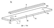
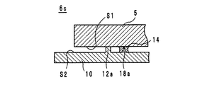
以下に、固定構造6aの第2の変形例に係る固定構造6cについて図面を参照しながら説明する。図7は、固定構造6cの外観斜視図である。図8は、固定構造6cの断面構造図である。図7は、折り返しミラー5が固定される前の状態を示している。また、図7には、左端近傍の領域Aの拡大図が示されている。図8は、図7の固定構造6cの左端近傍を示している。以下では、ハウジング10の法線方向を単に法線方向と呼び、折り返しミラー5の長手方向を単に長手方向と呼ぶ。
(Second modification)
Hereinafter, a fixing structure 6c according to a second modification of the fixing structure 6a will be described with reference to the drawings. FIG. 7 is an external perspective view of the fixing structure 6c. FIG. 8 is a sectional view of the fixing structure 6c. FIG. 7 shows a state before the
固定構造6aと固定構造6cとの相違点は、突起18a,18bの有無である。よって、以下では、固定構造6cについて、かかる相違点を中心に説明を行う。
The difference between the fixing structure 6a and the fixing structure 6c is the presence or absence of the
固定構造6cは、図7及び図8に示すように、突起18a,18b(図8では、突起18aのみ記載)を有している。該突起18a,18bは、長手方向において突起12a〜12cよりも変形し易い楔形の形状をなしている。具体的には、突起18a,18bは、法線方向及び長手方向に平行な断面において、法線方向の上方向にいくにしたがって細くなる三角形状の断面構造を有している。
As shown in FIGS. 7 and 8, the fixing structure 6c has
接着剤14は、図8に示すように、突起18a,18bに接触するように設けられている。より詳細には、接着剤14は、突起18a,18bを覆うように柱状に設けられている。
As shown in FIG. 8, the adhesive 14 is provided in contact with the
次に、固定構造6cにより、折り返しミラー5を固定する固定方法について図面を参照しながら説明する。図9は、該固定方法の工程断面図である。図9では、図8と同様に、折り返しミラー5の長手方向の左端近傍を拡大して示した。
Next, a fixing method for fixing the
まず、図9(a)に示すように、ハウジング10の突起18a,18b上に未硬化状態の接着剤14を塗布する(図9(a)では、突起18aのみ記載)。
First, as shown in FIG. 9A, the
次に、図9(b)に示すように、折り返しミラー5を主面S2に対して少し傾けることにより、主面S1と主面S2とを近接させて、主面S1を接着剤14に接触させる。これにより、接着剤14が、主面S1と主面S2とを繋ぐように柱状に変形する。
Next, as shown in FIG. 9 (b), the
次に、図8に示すように、主面S1に突起12a〜12c(図4では、突起12aのみ記載)を接触させて、折り返しミラー5とハウジング10との位置合わせを行う。
Next, as shown in FIG. 8, the
最後に、接着剤14に対してUVを照射して、該接着剤14を硬化させる。これにより、折り返しミラー5がハウジング10に固定される。
Finally, the adhesive 14 is irradiated with UV to cure the adhesive 14. Thereby, the
以上のような固定構造6c及びその固定方法によれば、固定構造6a及びその固定方法と同じ作用効果を奏することができる。更に、固定構造6c及びその固定方法によれば、突起18a,18bが設けられているので、未硬化状態の接着剤14が突起18a,18bに沿って塗布されるようになる。その結果、固定構造6cでは固定構造6aに比べて、未硬化状態の接着剤14は、法線方向に十分な高さを維持することが容易となる。よって、固定構造6c及びその固定方法によれば、固定構造6a及びその固定方法に比べ、接着剤14を主面S1と主面S2とを繋ぐように柱状に変形させることが容易となる。
According to the fixing structure 6c and the fixing method as described above, the same operational effects as the fixing structure 6a and the fixing method can be obtained. Furthermore, according to the fixing structure 6c and the fixing method thereof, since the
なお、固定構造6cにおいて、突起18a,18bは、図7及び図8に示した形状に限らない。例えば、突起18a,18bは、突起12a〜12cよりも細い円柱であってもよい。
In the fixing structure 6c, the
なお、固定構造6cにおいて、図10に示す突起18'a,18'bの斜視図に示すように、突起18'aと突起18'bとの間に接着剤14が設けられていてもよい。
In the fixing structure 6c, as shown in the perspective view of the
(第3の変形例)
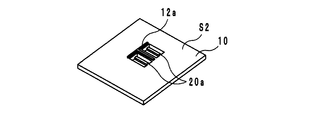
以下に、固定構造6aの第3の変形例に係る固定構造6dについて図面を参照しながら説明する。図11は、固定構造6dの外観斜視図である。図12は、固定構造6dの断面構造図である。図11は、折り返しミラー5が固定される前の状態を示している。また、図11には、左端近傍の領域Aの拡大図が示されている。図12は、図11の固定構造6dの左端近傍を示している。以下では、ハウジング10の法線方向を単に法線方向と呼び、折り返しミラー5の長手方向を単に長手方向と呼ぶ。
(Third Modification)
Hereinafter, a fixing
固定構造6aと固定構造6dとの相違点は、可変部20a,20bの有無である。よって、以下では、固定構造6dについて、かかる相違点を中心に説明を行う。
The difference between the fixed structure 6a and the fixed
図11に示すように、ハウジング10には、可変部20a,20bが設けられている。可変部20a,20bは、図11に示すようにコ字型に周囲が切り欠かれていると共に、図12に示すように、その法線方向の厚みがハウジング10のその他の部分に比べて薄く形成されて構成されている。これにより、可変部20a,20bは、ハウジング10のその他の部分に比べて、折り返しミラー5に近づく方向(すなわち、法線方向)に弾性変形しやすい構造をとっている。接着剤14は、図12に示すように、可変部20a,20b(図12では、可変部20bのみ記載)上に設けられる。
As shown in FIG. 11, the
次に、固定構造6dにより、折り返しミラー5を固定する固定方法について図面を参照しながら説明する。以下では、固定構造6dにより、折り返しミラー5を固定する固定方法と、固定構造6aにより、折り返しミラー5を固定する固定方法との相違点を中心に説明する。
Next, a fixing method for fixing the
固定構造6dの固定方法は、主面S1と主面S2とを近接させて、主面S1を接着剤14に接触させる方法において、固定構造6aの固定方法と相違点を有している。より詳細には、固定構造6aの固定方法では、折り返しミラー5を主面S2に対して少し傾けて、主面S1と主面S2とを近接させている。一方、固定構造6dの固定方法では、図12に示すように、可変部20a,20b(図12では、可変部20aのみ記載)を法線方向の上方向に押し上げることにより、可変部20a,20bを折り返しミラー5に近づけている。これにより、未硬化状態の接着剤14を、折り返しミラー5の主面S1に接触させて、主面S1と主面S2とを繋ぐ柱状に変形させる。
The fixing method of the fixing
固定構造6d及びその固定方法によれば、固定構造6a及びその固定方法と同じ作用効果を奏することができる。更に、固定構造6d及びその固定方法では、以下に説明するように、固定構造6a及びその固定方法に比べて、折り返しミラー5の位置合わせ時に、接着剤14が柱状から変形しにくい。より詳細には、固定構造6a及びその固定方法では、図5(b)に示す工程において接着剤14を変形させた後に、折り返しミラー5の位置合わせを行う必要があった。そのため、折り返しミラー5の位置合わせ時において、接着剤14が柱状から変形してしまうおそれがある。
According to the fixing
一方、固定構造6d及びその固定方法では、折り返しミラー5を傾けることなく、可変部20a,20bを押し上げることにより、接着剤14を柱状に変形させている。よって、固定構造6d及びその固定方法では、折り返しミラー5を位置合わせした後に、接着剤14を柱状に変形させることができる。その結果、固定構造6d及びその固定方法では、柱状に変形した接着剤14が、折り返しミラー5の位置合わせの工程において変形してしまうおそれがなくなる。
On the other hand, in the fixing
なお、突起12a〜12c及び可変部20a,20bの構造は、図11に示したものに限らない。以下に、突起12a〜12c及び可変部20a,20bの変形例について、図面を参照しながら説明する。図13は、第1の変形例に係る突起12a及び可変部20aの外観斜視図である。図14は、第2の変形例に係る突起12a及び可変部20aの外観斜視図である。図15は、第3の変形例に係る突起12a及び可変部20aの外観斜視図である。図16は、第3の変形例に係る突起12a及び可変部20aの断面構造図である。
Note that the structures of the
図13に示すように、突起12aは、可変部20aの周囲に設けられているコ字型の切り欠きを囲むように、コ字型を有していてもよい。図13に示す突起12aは、図3に示す突起12aよりも、折り返しミラー5と大きな面積で接触するようになるので、折り返しミラー5を安定して保持できる。
As shown in FIG. 13, the
また、図14に示すように、可変部20aは、2つ並ぶように設けられていてもよい。この場合、突起12aは、2つの可変部20aの間を延在する部分と2つの可変部20aに沿って延在する部分とからなるT字型を有している。
Moreover, as shown in FIG. 14, the two
また、図15及び図16に示すように、可変部20aには、主面S2から法線方向の上方向に突出する突起22が設けられていてもよい。該突起22は、可変部20aにおいて未硬化状態の接着剤14が塗布される部分の近くに設けられている。これにより、突起22は、未硬化状態の接着剤14をせき止めて、該未硬化状態の接着剤14が主面S2上に広がることを抑制する。ただし、突起22は、突起12aよりも低く形成されることが望ましい。これは、可変部20aを押し上げたときに、突起22と主面S1とが接触して、主面S1と接着剤14とが接触することを妨げないようにするためである。
As shown in FIGS. 15 and 16, the
(第4の変形例)
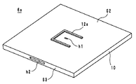
以下に、固定構造6aの第4の変形例に係る固定構造6eについて図面を参照しながら説明する。図17は、固定構造6eの突起12a近傍における外観斜視図である。図18は、固定構造6eの断面構造図である。以下では、ハウジング10の法線方向を単に法線方向と呼び、折り返しミラー5の長手方向を単に長手方向と呼ぶ。
(Fourth modification)
Hereinafter, a fixing structure 6e according to a fourth modification of the fixing structure 6a will be described with reference to the drawings. FIG. 17 is an external perspective view in the vicinity of the
固定構造6aと固定構造6eとの相違点は、突起12aの形状及び空洞SPの有無である。よって、以下では、固定構造6eについて、かかる相違点を中心に説明を行う。
The difference between the fixing structure 6a and the fixing structure 6e is the shape of the
突起12aは、図13に示した突起12aと同じく、コ字型を有している。また、主面S2において該突起12aに囲まれた領域内には、孔h1が設けられている。更に、ハウジング10の側面S3(すなわち、主面S2以外の表面)には、孔h2が設けられている。孔h1と孔h2とは、図18に示すように、空洞SPにより連通されている。
The
次に、固定構造6eにより、折り返しミラー5を固定する固定方法について図面を参照しながら説明する。以下では、固定構造6eにより、折り返しミラー5を固定する固定方法と、固定構造6aにより、折り返しミラー5を固定する固定方法との相違点を中心に説明する。
Next, a fixing method for fixing the
固定構造6eの固定方法は、接着剤14を柱状に変形させる方法において、固定構造6aの固定方法と相違点を有している。より詳細には、固定構造6aの固定方法では、折り返しミラー5を主面2に対して少し傾けて、主面S1と主面S2とを近接させている。一方、固定構造6eの固定方法では、図18に示すように、未硬化状態の接着剤14を孔h1上に塗布し、孔h2から空気を送り込むことにより、未硬化状態の接着剤14を風圧により法線方向の上方向に押し出している。これにより、未硬化状態の接着剤14は、主面S1と主面S2とを繋ぐように柱状に変形する。
The fixing method of the fixing structure 6e is different from the fixing method of the fixing structure 6a in the method of deforming the adhesive 14 into a columnar shape. More specifically, in the fixing method of the fixing structure 6a, the
固定構造6e及びその固定方法によれば、固定構造6a及びその固定方法と同じ作用効果を奏することができる。更に、固定構造6e及びその固定方法では、以下に説明するように、固定構造6a及びその固定方法に比べて、折り返しミラー5の位置合わせ時に、接着剤14が柱状から変形しにくい。より詳細には、固定構造6a及びその固定方法では、図5(b)に示す工程において接着剤14を変形させた後に、折り返しミラー5の位置合わせを行う必要があった。そのため、折り返しミラー5の位置合わせ時において、接着剤14が柱状から変形してしまうおそれがある。
According to the fixing structure 6e and its fixing method, the same operational effects as the fixing structure 6a and its fixing method can be achieved. Furthermore, in the fixing structure 6e and the fixing method thereof, as described below, the adhesive 14 is less likely to be deformed from the columnar shape when the
一方、固定構造6e及びその固定方法では、折り返しミラー5を傾けることなく、風圧により接着剤14を柱状に変形させている。よって、固定構造6e及びその固定方法では、折り返しミラー5を位置合わせした後に、接着剤14を柱状に変形させることができる。その結果、固定構造6e及びその固定方法では、柱状に変形した接着剤14が、折り返しミラー5の位置合わせの工程において変形してしまうおそれがなくなる。
On the other hand, in the fixing structure 6e and its fixing method, the adhesive 14 is deformed into a columnar shape by wind pressure without tilting the
(その他の変形例)
なお、前記各固定方法において、接着剤14は、主面S2にのみ塗布されているが、主面S1に塗布されてもよいし、主面S1及び主面S2の両方に塗布されてもよい。
(Other variations)
In each fixing method, the adhesive 14 is applied only to the main surface S2, but may be applied to the main surface S1, or may be applied to both the main surface S1 and the main surface S2. .
また、固定構造6a〜6eにおいて、突起12a〜12cは、主面S2から突出しているが、主面S1から突出していてもよい。この場合、突起12a〜12cは、主面S2に接触することにより、折り返しミラー5とハウジング10との位置決めをする。
In the fixing structures 6a to 6e, the
また、固定構造6a〜6eにおいてハウジング10に固定されている光学素子は、折返しミラー5である。しかしながら、光学素子は、折返しミラー5に限らず、光学レンズ等であってもよい。光学素子が光学レンズである場合には、材料として、例えば、ゼオネックス330Rが用いられる。
The optical element fixed to the
S1,S2 主面
SP 空洞
1 光走査装置
2 光源ユニット
3 ポリゴンミラー
4a,4b 走査レンズ
5 折り返しミラー
6a〜6e 固定構造
10 ハウジング
12a〜12c 突起
14 接着剤
16 領域
18a,18b,18’a,18'b,22 突起
20a,20b 可変部
S1, S2 main
Claims (16)
前記第1の主面と隙間をあけた状態で対向している第2の主面を有しているハウジングと、
前記第1の主面又は該第2の主面の何れか一方から突出して、該第1の主面又は該第2の主面の他方に接触することにより、前記ハウジングと前記光学素子とを位置決めする第1の突起と、
前記第1の突起から離れた位置において、前記第1の主面と前記第2の主面とを繋ぐように設けられている接着剤と、
を備えていることを特徴とする固定構造。 An optical element having a first major surface;
A housing having a second main surface facing the first main surface with a gap therebetween;
The housing and the optical element are protruded from either the first main surface or the second main surface and contact the other of the first main surface or the second main surface. A first protrusion for positioning;
An adhesive provided to connect the first main surface and the second main surface at a position away from the first projection;
A fixing structure characterized by comprising:
前記接着剤は、前記長手方向における前記光学素子の中点よりも、該長手方向における該光学素子の端部に近い位置に設けられていること、
を特徴とする請求項1に記載の固定構造。 The optical element has a structure having a longitudinal direction,
The adhesive is provided closer to the end of the optical element in the longitudinal direction than the midpoint of the optical element in the longitudinal direction;
The fixing structure according to claim 1.
を特徴とする請求項1又は請求項2のいずれかに記載の固定構造。 The Young's modulus of the adhesive is smaller than the Young's modulus of the first protrusion,
The fixing structure according to claim 1, wherein:
を特徴とする請求項1ないし請求項3のいずれかに記載の固定構造。 The adhesive is a photo-curing resin;
The fixing structure according to any one of claims 1 to 3, wherein:
前記ハウジングは、
前記長手方向において、前記第1の突起よりも変形し易い第2の突起を、
更に有し、
前記接着剤は、前記第2の突起に接触するように設けられていること、
を特徴とする請求項1ないし請求項4のいずれかに記載の固定構造。 The optical element has a structure having a longitudinal direction,
The housing is
In the longitudinal direction, a second protrusion that is more easily deformed than the first protrusion,
In addition,
The adhesive is provided in contact with the second protrusion;
The fixing structure according to any one of claims 1 to 4, characterized in that:
を特徴とする請求項1ないし請求項5のいずれかに記載の固定構造。 The housing has a structure in which the portion provided with the adhesive is easily elastically deformed in a direction approaching the optical element as compared with other portions;
The fixing structure according to any one of claims 1 to 5, wherein
を特徴とする請求項1ないし請求項4のいずれかに記載の固定構造。 The housing is provided with a cavity that communicates between a portion where the adhesive is provided and a surface other than the second main surface;
The fixing structure according to any one of claims 1 to 4, characterized in that:
前記接着剤が設けられている部分を囲んでいると共に、該接着剤に対する濡れ性が前記第2の主面よりも低い領域を、
更に有していること、
を特徴とする請求項1ないし請求項7のいずれかに記載の固定構造。 The housing is
Surrounding the portion where the adhesive is provided, and a region where the wettability to the adhesive is lower than the second main surface,
In addition,
The fixing structure according to claim 1, wherein:
を特徴とする請求項1ないし請求項8のいずれかに記載の固定構造。 The adhesive is a resin having a glass transition point of 110 ° C. or lower,
The fixing structure according to claim 1, wherein:
前記接着剤の高さは、0.1mm以上1mm以下であること、
を特徴とする請求項1ないし請求項9のいずれかに記載の固定構造。 The adhesive is a resin having a viscosity before curing at 25 ° C. of 6000 mPa · s or more and 30000 mPa · s or less,
The height of the adhesive is 0.1 mm or more and 1 mm or less;
The fixing structure according to any one of claims 1 to 9, wherein:
を特徴とする請求項1ないし請求項10のいずれかに記載の固定構造。 The first protrusion is formed integrally with the second main surface;
The fixing structure according to claim 1, wherein:
を特徴とする光走査装置。 A fixing structure according to any one of claims 1 to 11 is provided.
An optical scanning device characterized by the above.
を特徴とする画像形成装置。 Comprising the optical scanning device according to claim 12;
An image forming apparatus.
前記第1の主面又は前記第2の主面の少なくともいずれか一方に接着剤を塗布する工程と、
前記第1の主面又は前記第2の主面のいずれか一方に設けられた突起に該第1の主面又は該第2の主面のいずれか他方を接触させて、前記光学素子と前記ハウジングとの位置合わせを行う工程と、
前記第1の主面と前記第2の主面とを近接させて、該第1の主面と該第2の主面とを繋ぐように前記接着剤を変形させる工程と、
前記接着剤を硬化させる工程と、
を備えていること、
を特徴とする固定方法。 A fixing method for fixing an optical element having a first main surface and a housing having a second main surface,
Applying an adhesive to at least one of the first main surface or the second main surface;
Either the first main surface or the second main surface is brought into contact with a protrusion provided on either the first main surface or the second main surface, and the optical element and the A process of aligning with the housing;
Deforming the adhesive so as to bring the first main surface and the second main surface close to each other and connect the first main surface and the second main surface;
Curing the adhesive;
Having
The fixing method characterized by.
前記接着剤を変形させる工程では、前記ハウジングの該接着剤が設けられる部分を、前記光学素子に近づけるように弾性変形させること、
を特徴とする請求項14に記載の固定方法。 The housing has a structure in which the portion provided with the adhesive is easily elastically deformed in a direction approaching the optical element as compared with other portions,
In the step of deforming the adhesive, elastically deforming a portion of the housing on which the adhesive is provided so as to approach the optical element;
The fixing method according to claim 14.
前記接着剤を塗布する工程では、前記第2の主面に塗布し、
前記接着剤を変形させる工程では、前記第2の主面以外の表面側から前記空洞に空気を送り込むこと、
を特徴とする請求項14に記載の固定方法。 The housing is provided with a cavity communicating between a portion where the adhesive is provided and a surface other than the second main surface,
In the step of applying the adhesive, it is applied to the second main surface,
In the step of deforming the adhesive, air is sent into the cavity from the surface side other than the second main surface;
The fixing method according to claim 14.
Priority Applications (1)
| Application Number | Priority Date | Filing Date | Title |
|---|---|---|---|
| JP2008237896A JP5131110B2 (en) | 2008-09-17 | 2008-09-17 | FIXING STRUCTURE, OPTICAL SCANNING DEVICE, IMAGE FORMING DEVICE, AND FIXING METHOD |
Applications Claiming Priority (1)
| Application Number | Priority Date | Filing Date | Title |
|---|---|---|---|
| JP2008237896A JP5131110B2 (en) | 2008-09-17 | 2008-09-17 | FIXING STRUCTURE, OPTICAL SCANNING DEVICE, IMAGE FORMING DEVICE, AND FIXING METHOD |
Publications (2)
| Publication Number | Publication Date |
|---|---|
| JP2010072196A true JP2010072196A (en) | 2010-04-02 |
| JP5131110B2 JP5131110B2 (en) | 2013-01-30 |
Family
ID=42204058
Family Applications (1)
| Application Number | Title | Priority Date | Filing Date |
|---|---|---|---|
| JP2008237896A Expired - Fee Related JP5131110B2 (en) | 2008-09-17 | 2008-09-17 | FIXING STRUCTURE, OPTICAL SCANNING DEVICE, IMAGE FORMING DEVICE, AND FIXING METHOD |
Country Status (1)
| Country | Link |
|---|---|
| JP (1) | JP5131110B2 (en) |
Cited By (7)
| Publication number | Priority date | Publication date | Assignee | Title |
|---|---|---|---|---|
| WO2011118711A1 (en) | 2010-03-26 | 2011-09-29 | 三菱重工業株式会社 | Battery pack and battery control system |
| JP2013148842A (en) * | 2012-01-23 | 2013-08-01 | Brother Ind Ltd | Optical scanning device |
| JP2016094986A (en) * | 2014-11-14 | 2016-05-26 | 株式会社フジクラ | Flat plate support structure and manufacturing method thereof |
| JP2016111133A (en) * | 2014-12-04 | 2016-06-20 | 株式会社リコー | Light source device and light source unit |
| JP2016224091A (en) * | 2015-05-27 | 2016-12-28 | 京セラドキュメントソリューションズ株式会社 | Optical scanner and image forming apparatus including the optical scanner |
| JP2022033131A (en) * | 2017-01-31 | 2022-02-28 | パイオニア株式会社 | Wavelength selection element and manufacturing method therefor |
| US12127830B2 (en) | 2019-04-22 | 2024-10-29 | Dexcom, Inc. | Preconnected analyte sensors |
Citations (6)
| Publication number | Priority date | Publication date | Assignee | Title |
|---|---|---|---|---|
| JP2000131583A (en) * | 1998-10-22 | 2000-05-12 | Minolta Co Ltd | Structure for holding optical member |
| JP2003066299A (en) * | 2001-08-24 | 2003-03-05 | Canon Inc | Method for fixing precision member and holding structure of precision member |
| JP2004327908A (en) * | 2003-04-28 | 2004-11-18 | Ricoh Co Ltd | Method and structure for bonding electro-optical devices |
| JP2006220956A (en) * | 2005-02-10 | 2006-08-24 | Ricoh Co Ltd | Method of fixing and joining optical elements, fixing and joining apparatus, optical scanner and image forming apparatus |
| JP2007216632A (en) * | 2006-02-20 | 2007-08-30 | Toshiba Tec Corp | Inkjet head unit |
| JP2007298684A (en) * | 2006-04-28 | 2007-11-15 | Brother Ind Ltd | Scanning optical device |
-
2008
- 2008-09-17 JP JP2008237896A patent/JP5131110B2/en not_active Expired - Fee Related
Patent Citations (6)
| Publication number | Priority date | Publication date | Assignee | Title |
|---|---|---|---|---|
| JP2000131583A (en) * | 1998-10-22 | 2000-05-12 | Minolta Co Ltd | Structure for holding optical member |
| JP2003066299A (en) * | 2001-08-24 | 2003-03-05 | Canon Inc | Method for fixing precision member and holding structure of precision member |
| JP2004327908A (en) * | 2003-04-28 | 2004-11-18 | Ricoh Co Ltd | Method and structure for bonding electro-optical devices |
| JP2006220956A (en) * | 2005-02-10 | 2006-08-24 | Ricoh Co Ltd | Method of fixing and joining optical elements, fixing and joining apparatus, optical scanner and image forming apparatus |
| JP2007216632A (en) * | 2006-02-20 | 2007-08-30 | Toshiba Tec Corp | Inkjet head unit |
| JP2007298684A (en) * | 2006-04-28 | 2007-11-15 | Brother Ind Ltd | Scanning optical device |
Cited By (8)
| Publication number | Priority date | Publication date | Assignee | Title |
|---|---|---|---|---|
| WO2011118711A1 (en) | 2010-03-26 | 2011-09-29 | 三菱重工業株式会社 | Battery pack and battery control system |
| JP2013148842A (en) * | 2012-01-23 | 2013-08-01 | Brother Ind Ltd | Optical scanning device |
| JP2016094986A (en) * | 2014-11-14 | 2016-05-26 | 株式会社フジクラ | Flat plate support structure and manufacturing method thereof |
| JP2016111133A (en) * | 2014-12-04 | 2016-06-20 | 株式会社リコー | Light source device and light source unit |
| JP2016224091A (en) * | 2015-05-27 | 2016-12-28 | 京セラドキュメントソリューションズ株式会社 | Optical scanner and image forming apparatus including the optical scanner |
| JP2022033131A (en) * | 2017-01-31 | 2022-02-28 | パイオニア株式会社 | Wavelength selection element and manufacturing method therefor |
| US12127830B2 (en) | 2019-04-22 | 2024-10-29 | Dexcom, Inc. | Preconnected analyte sensors |
| US12144615B2 (en) | 2019-04-22 | 2024-11-19 | Dexcom, Inc. | Preconnected analyte sensors |
Also Published As
| Publication number | Publication date |
|---|---|
| JP5131110B2 (en) | 2013-01-30 |
Similar Documents
| Publication | Publication Date | Title |
|---|---|---|
| JP5131110B2 (en) | FIXING STRUCTURE, OPTICAL SCANNING DEVICE, IMAGE FORMING DEVICE, AND FIXING METHOD | |
| JP5560316B2 (en) | Image reading apparatus and image forming apparatus | |
| US8922606B2 (en) | Rotational polygon mirror having convex reflection surfaces and light scanning unit employing the same | |
| EP2458414A1 (en) | Polygon mirror assembly, light scanning unit employing polygon mirror assembly, and image forming apparatus | |
| US20130188004A1 (en) | Light beam scanning device and image forming apparatus | |
| KR100818378B1 (en) | Optical element, optical scanning apparatus, and image forming apparatus using optical element, and method and apparatus for fixedly joining optical element | |
| US7940440B2 (en) | Laser scanning device and image forming apparatus | |
| JP2009198679A (en) | Fixing structure and fixing method for optical element, laser beam scanner, and image forming apparatus | |
| CN103487935B (en) | Optical scanner and imaging device | |
| JP4444067B2 (en) | Optical element adhesive fixing method and optical scanning device | |
| JP5151064B2 (en) | Method for fixing and joining optical elements | |
| JP2005121985A (en) | Positioning tool for optical element, method of positioning, optical element, optical scanner and method of adhering | |
| JP4792938B2 (en) | Laser scanning optical device | |
| JP2007127793A (en) | Laser scanning optical apparatus | |
| JP2009002988A (en) | Laser scanner and image forming apparatus | |
| JP2009080174A (en) | Light source device | |
| JP5887950B2 (en) | Optical scanning device | |
| JP5868268B2 (en) | Optical scanning device and image forming apparatus having the same | |
| JP5799135B2 (en) | Image reading apparatus and image forming apparatus | |
| JP4867809B2 (en) | Laser scanning apparatus and image forming apparatus | |
| KR20080067410A (en) | Image forming lens for Gwangju company unit, Gwangju unit and image forming device using the same | |
| JP6299271B2 (en) | Print head and image forming apparatus | |
| JP2009198678A (en) | Fixing structure and fixing method for optical element, laser beam scanner, and image forming apparatus | |
| JP2023072999A (en) | Optical scanner and image formation device provided with the same, and method for manufacturing optical scanner | |
| JP4172538B2 (en) | Anamorphic imaging element and optical scanning device |
Legal Events
| Date | Code | Title | Description |
|---|---|---|---|
| A621 | Written request for application examination |
Free format text: JAPANESE INTERMEDIATE CODE: A621 Effective date: 20110307 |
|
| A977 | Report on retrieval |
Free format text: JAPANESE INTERMEDIATE CODE: A971007 Effective date: 20120424 |
|
| A131 | Notification of reasons for refusal |
Free format text: JAPANESE INTERMEDIATE CODE: A131 Effective date: 20120508 |
|
| A521 | Written amendment |
Free format text: JAPANESE INTERMEDIATE CODE: A523 Effective date: 20120706 |
|
| RD02 | Notification of acceptance of power of attorney |
Free format text: JAPANESE INTERMEDIATE CODE: A7422 Effective date: 20120706 |
|
| A131 | Notification of reasons for refusal |
Free format text: JAPANESE INTERMEDIATE CODE: A131 Effective date: 20120724 |
|
| A521 | Written amendment |
Free format text: JAPANESE INTERMEDIATE CODE: A523 Effective date: 20120921 |
|
| TRDD | Decision of grant or rejection written | ||
| A01 | Written decision to grant a patent or to grant a registration (utility model) |
Free format text: JAPANESE INTERMEDIATE CODE: A01 Effective date: 20121009 |
|
| A01 | Written decision to grant a patent or to grant a registration (utility model) |
Free format text: JAPANESE INTERMEDIATE CODE: A01 |
|
| A61 | First payment of annual fees (during grant procedure) |
Free format text: JAPANESE INTERMEDIATE CODE: A61 Effective date: 20121022 |
|
| FPAY | Renewal fee payment (event date is renewal date of database) |
Free format text: PAYMENT UNTIL: 20151116 Year of fee payment: 3 |
|
| R150 | Certificate of patent or registration of utility model |
Free format text: JAPANESE INTERMEDIATE CODE: R150 |
|
| LAPS | Cancellation because of no payment of annual fees |