JP2010072167A - Animation card - Google Patents
Animation card Download PDFInfo
- Publication number
- JP2010072167A JP2010072167A JP2008237656A JP2008237656A JP2010072167A JP 2010072167 A JP2010072167 A JP 2010072167A JP 2008237656 A JP2008237656 A JP 2008237656A JP 2008237656 A JP2008237656 A JP 2008237656A JP 2010072167 A JP2010072167 A JP 2010072167A
- Authority
- JP
- Japan
- Prior art keywords
- section
- film gauge
- gauge
- card
- background
- Prior art date
- Legal status (The legal status is an assumption and is not a legal conclusion. Google has not performed a legal analysis and makes no representation as to the accuracy of the status listed.)
- Granted
Links
Images


Landscapes
- Credit Cards Or The Like (AREA)
- Displays For Variable Information Using Movable Means (AREA)
Abstract
Description
本発明は、複合画像で構成される下絵の上で、フィルムゲージをスライド移動させることで、絵が動いているかの如き視覚的効果を与える動画カードに関する。この動画カードは、例えば、菓子、食品、雑貨のオマケ、知育玩具、グリーティングカードとして使用することが可能である。 The present invention relates to a moving image card that gives a visual effect as if a picture is moving by sliding a film gauge on a sketch composed of composite images. This moving picture card can be used as, for example, a confectionery, food, miscellaneous gift, an educational toy, and a greeting card.
「下絵」と「フィルムゲージ」を利用して、パラパラ漫画とよく似た原理で、あたかも絵が動いているかのような視覚的効果を与える技術は、従来から知られている(例えば、特許文献1、2)。その原理を簡単に説明すると、次の通りである。 A technique that gives a visual effect as if a picture is moving on the basis of a principle similar to that of a flip book by using “understory” and “film gauge” has been conventionally known (for example, patent literature). 1, 2). The principle will be briefly described as follows.
≪画素が2つの場合:図1、図2≫
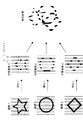
図1は、「複合画像で構成される下絵」の作成原理を示している。ここでは、複合画像は、2つの画素から構成される。まず、画素1、2をそれぞれ等間隔“α”で間引いて、「残像」と「欠け」が繰り返す中間画素を作成する。次に、中間画像1の「欠け」部分に、中間画像2の「残像」部分が一致するようにして、両者を組み合わせて複合画像を作成する。
<< When there are two pixels: FIGS. 1 and 2 >>
FIG. 1 shows the principle of creating a “background picture composed of composite images”. Here, the composite image is composed of two pixels. First, the pixels 1 and 2 are thinned out at equal intervals “α” to create intermediate pixels in which “afterimage” and “missing” repeat. Next, the “afterimage” portion of the intermediate image 2 matches the “missing” portion of the intermediate image 1, and a composite image is created by combining the two.
一方、図2に示したフィルムゲージは、透明の基材上に「黒塗りの細長い帯状領域」を等間隔で印刷したものであって、「帯状領域の幅」と「各帯状領域間の間隔」とが等しい(共に“α”)。
このフィルムゲージを複合画像上に重ね合わせて、両者を相対的にスライドさせると、図2に示したように、中間画素1の「残像」がフィルムゲージ上の各帯状領域間の透明領域にきたときに星形模様が視認される(A)。
一方、中間画素2の「残像」がフィルムゲージ上の各帯状領域間の透明領域にきたときに丸形模様が視認される(B)。
On the other hand, the film gauge shown in FIG. 2 is obtained by printing “black elongated strips” on a transparent substrate at equal intervals, and the “width of strips” and the “interval between strips”. Are equal (both are “α”).
When this film gauge is overlaid on the composite image and both are slid relative to each other, as shown in FIG. 2, the “afterimage” of the intermediate pixel 1 comes to a transparent area between the strip-like areas on the film gauge. Sometimes a star pattern is visible (A).
On the other hand, when the “afterimage” of the intermediate pixel 2 comes to the transparent area between the band-like areas on the film gauge, a round pattern is visually recognized (B).
以上の相対スライド動作を適度な速度で行うと、人間の目には、あたかも星形模様と丸形模様が動的に変化しているかのように視認される。 When the above relative sliding motion is performed at an appropriate speed, it is visually recognized by human eyes as if the star pattern and the round pattern are dynamically changing.
≪画素が3つの場合:図3、図4≫
以上に説明した画素が2つの場合は、(i)画素を間引く際の「残像」と「欠け」の幅寸法を等しくし(“α”)、かつ、(ii)フィルムゲージ上の「帯状領域の幅」および「各帯状領域間の間隔」を共にこの“α”と等しくしている。
<< When there are three pixels: FIGS. 3 and 4 >>
When there are two pixels as described above, (i) the width dimensions of “afterimage” and “missing” when thinning out the pixels are equal (“α”), and (ii) “band-like region on the film gauge” The “width” and the “interval between the band-like regions” are both equal to “α”.
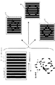
画素が3つの場合は、図3、図4に示したように、(i)画素を間引く際に、「欠け」の幅寸法“β”を「残像」の幅寸法“γ”の2倍とし、(ii)フィルムゲージ上における「帯状領域の幅」を「欠け」の幅寸法“β”に等しく、「各帯状領域間の間隔」を「残像」の幅寸法“γ”に等しくする。
「欠け」の幅寸法“β”が「残像」の幅寸法“γ”の2倍であるため、中間画素1の「欠け」部分に他の2つの中間画素2、3の「残像」を収めることができ、したがって、3つの画素からなる複合画像を作成することができる。
When there are three pixels, as shown in FIGS. 3 and 4, (i) when thinning out the pixels, the width dimension “β” of “missing” is set to twice the width dimension “γ” of “afterimage”. (Ii) The “width of the belt-like region” on the film gauge is made equal to the width dimension “β” of “chip”, and the “interval between the belt-like regions” is made equal to the width dimension “γ” of “afterimage”.
Since the width dimension “β” of “missing” is twice the width dimension “γ” of “afterimage”, the “afterimage” of the other two
そして、図4に示したように、中間画素1の「残像」がフィルムゲージ上の各帯状領域間の透明領域にきたときに星形模様が視認される(A)。中間画素2の「残像」がフィルムゲージ上の各帯状領域間の透明領域にきたときに丸形模様が視認される(B)。中間画素3の「残像」がフィルムゲージ上の各帯状領域間の透明領域にきたときに菱形模様が視認される(C)。
Then, as shown in FIG. 4, a star pattern is visually recognized when the “afterimage” of the intermediate pixel 1 comes to a transparent area between the band-like areas on the film gauge (A). A circular pattern is visually recognized when the “afterimage” of the intermediate pixel 2 comes to a transparent region between the strip regions on the film gauge (B). A rhombus pattern is visually recognized when the “afterimage” of the
同様の考え方で、画素が4つ、5つの場合にも、複合画像および対応するフィルムゲージを作成できる。 In the same way, a composite image and a corresponding film gauge can be created when there are four or five pixels.
以上に説明した例では、ストライプ状のフィルムゲージを使用しているが、格子状のフィルムゲージと、これと対応する下絵とを利用して、同様の視覚的効果を与える構成も知られている。
ストライプ状のフィルムゲージの場合には、視覚的効果を得るために「下絵」と「フィルムゲージ」を相対移動させる方向は、ストライプに直交する1方向に限られる。これに対して、格子状のフィルムゲージの場合には、タテ、ヨコ、ナナメのいずれの方向に相対移動させた場合であっても、視覚的効果を得ることができる。
In the example described above, a striped film gauge is used, but a configuration that gives a similar visual effect using a lattice-shaped film gauge and a corresponding sketch is also known. .
In the case of a striped film gauge, the direction in which the “background” and the “film gauge” are relatively moved to obtain a visual effect is limited to one direction orthogonal to the stripe. On the other hand, in the case of a lattice-shaped film gauge, a visual effect can be obtained even if the film is relatively moved in any of the vertical, horizontal, and slant directions.
本発明の第1の目的は、上記視覚的効果によって得られる動画を利用した動画カードを提供し、これにより、販売促進効果を高めることである。すなわち、動画カードを菓子等の商品のオマケとすれば、当該商品の販売促進が期待できる。また、動画カード自体を知育玩具、あるいはグリーティングカードとすれば、これら商品の販売促進が期待できる。 The first object of the present invention is to provide a moving picture card using a moving picture obtained by the visual effect, thereby enhancing the sales promotion effect. That is, if the moving image card is a bonus for a product such as confectionery, sales promotion of the product can be expected. Further, if the video card itself is an educational toy or a greeting card, sales of these products can be expected.
「フィルムゲージ」と「下絵」を重ね合わせて相対スライドさせることで動画を生じさせる場合、相対スライドする「フィルムゲージ」および「下絵」は、適度に密着していることが好ましい。両者の隙間が大きいと、視覚的効果として得られる動画もボヤケたものとなってしまう。
したがって、本発明の第2の目的は、動画カードに設けた「フィルムゲージ」と「下絵」の適度な密着性を実現することである。
In the case where a moving image is generated by superimposing the “film gauge” and the “rough picture” and sliding relative to each other, it is preferable that the “film gauge” and “rough picture” that are relatively slid are in close contact with each other. If the gap between the two is large, the moving image obtained as a visual effect is blurred.
Therefore, the second object of the present invention is to realize appropriate adhesion between a “film gauge” and a “background picture” provided on a moving picture card.
また、本発明の第3の目的は、上記動画カードの具体的構造をシンプル化して、製造を簡単にすることである。 In addition, a third object of the present invention is to simplify the concrete structure of the moving picture card and simplify the manufacture.
本発明の動画カードは、「複合画像で構成される下絵が表示された下絵フラップ」と「当該下絵に対応するフィルムゲージ」とを重ね、両者を相対的にスライド移動させることで、動画を生じさせる。
当該動画カードは、連設線において相対回動可能に連設された表紙と裏表紙を備え、表紙または裏表紙の一方の内面に下絵フラップが立設されるとともに、他方の内面にフィルムゲージが保持されている。立設された下絵フラップは、フィルムゲージの下面側に差し込まれている。
表紙と裏表紙を相対的に回動させると、これと連動して下絵フラップがフィルムゲージに対して相対的にスライドし、これにより上記動画が生じる。
The moving image card of the present invention generates a moving image by overlaying “a background flap displaying a background composed of composite images” and “a film gauge corresponding to the background” and sliding both of them relatively. Let
The moving picture card includes a front cover and a back cover that are connected to each other so as to be relatively rotatable on a continuous line, a background flap is erected on one inner surface of the front cover or the back cover, and a film gauge is provided on the other inner surface. Is retained. The standing background flap is inserted into the lower surface side of the film gauge.
When the front cover and the back cover are rotated relative to each other, the background flap slides relative to the film gauge in conjunction with the rotation, and the moving image is generated.
「下絵」は、例えば図1〜4で説明したような「残像」と「欠け」で構成される複数の画素から作成される複合画像である。また、下絵に「対応するフィルムゲージ」とは、複合画像の「残像」および「欠け」に対応した「透明領域」および「不透明領域」を含み、相対スライドによって動画を生じさせるフィルムゲージを意味する。
また、フィルムゲージは、ストライプ状および格子状のいずれであってもよく、対応する下絵(複合画像)と相対スライドすることで動画を生じさせる。
The “underlay” is a composite image created from a plurality of pixels composed of “afterimage” and “missing” as described with reference to FIGS. Also, the “corresponding film gauge” in the sketch means a film gauge that includes “transparent area” and “opaque area” corresponding to “afterimage” and “missing” of the composite image, and produces a moving image by relative sliding. .
The film gauge may be either a stripe shape or a lattice shape, and a moving image is generated by sliding relative to a corresponding background picture (composite image).
例えば、本発明の動画カードを菓子のオマケとして使用し、「フィルムゲージ」および「下絵」による上述の視覚的効果で得られる動画を、「菓子と関連する」もの、あるいは人気キャラクターとすることで、宣伝効果あるいは販売促進効果を高めることができる。 For example, by using the video card of the present invention as a bonus for confectionery, the video obtained with the above-mentioned visual effect by “film gauge” and “rough sketch” is made “something related to confectionery” or a popular character. , The advertising effect or sales promotion effect can be enhanced.
「菓子と関連する」とは、菓子の種類、その他の内容と関連するものに限られず、当該菓子を提供するメーカーと関連するもの等、広い意味で、何らかの関連があればよい。また、知育玩具やグリーティングカードとして、本願発明の動画カードを利用した場合にも販売促進効果を得ることができる。 “Relevant to confectionery” is not limited to the type of confectionery or other contents, but may be somehow related in a broad sense such as those related to the manufacturer that provides the confectionery. Moreover, the sales promotion effect can be obtained also when the moving image card of the present invention is used as an educational toy or a greeting card.
また、本発明の動画カードにおいては、表紙または裏表紙の一方の内面で、下絵フラップを連設線から一定距離だけ離れた位置から立ち上がるよう立設し、この下絵フラップをフィルムゲージの下面側に差し込むように構成することが好ましい。 Further, in the moving image card of the present invention, the background flap is erected on the inner surface of one of the front cover and the back cover so as to rise from a position separated from the continuous line by a certain distance, and the background flap is placed on the lower surface side of the film gauge. It is preferable to configure so as to be inserted.
これにより、「フィルムゲージ」と「下絵フラップ」が適度に密着するので、相対スライドにより得られる動画がクリアなものとなる。 As a result, the “film gauge” and the “background flap” are in close contact with each other, and the moving image obtained by the relative slide becomes clear.
また、本発明の動画カードは、折罫を介して一列に連設された第1〜第5の5区画からなる1枚の透明シート基材から構成するのが好ましい。
この場合、第3区画と第4区画との間の折罫が、上記連設線を構成する。第4区画上に折り畳まれた第5区画にゲージが直接印刷されて上記フィルムゲージとして機能する。また、第3区画上に折り畳まれた第2区画に連設された第1区画に、複合画像が表示される。この第1区画は、上記下絵フラップとして、第4区画と第5区画の間に差し込まれる。
Moreover, it is preferable to comprise the moving image card of this invention from the transparent sheet base material of 1 sheet which consists of 1st-5th 5 divisions arranged in a row through the crease.
In this case, the crease between the third section and the fourth section constitutes the continuous line. A gauge is directly printed on the fifth section folded on the fourth section and functions as the film gauge. In addition, the composite image is displayed in the first section connected to the second section folded on the third section. The first section is inserted between the fourth section and the fifth section as the background flap.
このように構成した場合には、第5区画にフィルムゲージが直接印刷されているため、「開口を備えた基材を用意して、当該開口を塞ぐようにフィルムゲージを貼り付ける」という面倒な工程が不要となり、構造がシンプルで製造が簡単化できる。 In this case, since the film gauge is directly printed in the fifth section, it is troublesome to “prepare a base material having an opening and attach the film gauge so as to close the opening”. No process is required, the structure is simple, and manufacturing can be simplified.
この場合、上記ゲージを透明シート基材の全面に印刷して、複合画像は、別のシート片に表示された上で第1区画上に固定するようにしてもよい。このように構成すれば、透明シート基材上の特定の領域に限定してゲージを印刷する必要がなく、全面にゲージ印刷した透明シート基材を使用して動画カードを作成できるので、製造工程が簡単となる。 In this case, the gauge may be printed on the entire surface of the transparent sheet base material, and the composite image may be fixed on the first section after being displayed on another sheet piece. By configuring in this way, there is no need to print a gauge limited to a specific area on the transparent sheet substrate, and a moving picture card can be created using a transparent sheet substrate that has been gauge printed on the entire surface. Becomes easy.
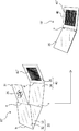
本発明の実施形態を添付の図面を参照して以下に詳細に説明する。図5は、本発明の第1実施形態に係る動画カード10を説明する分解斜視図である。
Embodiments of the present invention will be described in detail below with reference to the accompanying drawings. FIG. 5 is an exploded perspective view illustrating the moving
≪第1実施形態:図5〜図7≫
動画カード10は、紙、プラスチック、その他の適度な剛性を有するシート基材を折り畳んで構成される。図示の例では、折罫a、b、c、dを介して連設された5つの区画11〜15で構成される紙基材を使用している。
詳細は以下に説明するが、第5区画15がフィルムゲージ45を保持するとともに、表面に複合画像26が表示された第1区画11(下絵フラップ)が、フィルムゲージ45の下方で相対スライドすることで、動画を生じさせる(図6)。
First Embodiment: FIGS. 5 to 7
The moving
As will be described in detail below, the
下絵フラップとして機能する第1区画11の表面には、複合画像26が表示される。複合画像26は、直接印刷されていても、別のシートに印刷したものを貼り付けてもよい。
また、第2区画12と第3区画13は、重ね合わせて接着することで、表紙20を構成する。
A
Moreover, the
第5区画15の中央には、矩形の開口18が形成されていて、当該開口18を塞ぐようにフィルムゲージ45が貼り付けられる。第5区画15にフィルムゲージ45を貼り付けた後、第5区画15を第4区画14上に重ねるように折り畳む。このとき、複合画像26が表示された第1区画11を、第5区画15と第4区画14の間に挟み込む。
第5区画15は、15aで示した両サイドの領域において、第4区画14に接着され、裏表紙40を構成する。第1区画11(下絵フラップ)は、第5区画15と第4区画14に挟まれた状態でスライド移動することが可能である。
A
The
以上のようにして動画カード10を組み立てると、表紙20と裏表紙40は、折罫(連設線)cにおいて相対回動可能に連設された状態となる。表紙20と裏表紙40を相対的に回動させると、これに伴って、第1区画11(下絵フラップ)が、第5区画15に保持されたフィルムゲージ45の下面側で相対的にスライド移動する。
When the moving
下絵フラップ11(第1区画)は、最終的には、第4区画14と第5区画15との間に挟まれた状態で、第4区画14の表面に沿って延在するが、「表紙20の内面から立設する下絵フラップ11を、第5区画15に保持されたフィルムゲージ45の下面側に差し込んだもの」として把握することができる。
ただし、各構成要素の具体的な形状は、図示のものに限られず、適宜の形態を採用することが可能である。
The background flap 11 (first section) finally extends along the surface of the
However, the specific shape of each component is not limited to the illustrated one, and an appropriate form can be adopted.
また、図示の例では、下絵フラップ11が表紙20の内面から立設され、フィルムゲージ45が裏表紙40の内面に保持されているが、逆の構成であってもよい。すなわち、裏表紙40の内面から下絵フラップ11が立設され、表紙20の内面にフィルムゲージ45が保持されていてもよい。
In the illustrated example, the
折罫a〜dの具体的構成は、これに沿って折り畳むことが可能なものであれば、特に限定されない。ただ、折罫aは、複数の貫通切込みが一定間隔をおいて連続するミシン罫とすることが好ましく、これにより(押罫と比べて)、表紙20と裏表紙40との回動、およびこれに伴う下絵フラップ11のスライド移動がスムーズとなる。
The specific structure of the creases a to d is not particularly limited as long as it can be folded along this. However, it is preferable that the crease a be a sewing machine rule in which a plurality of through cuts are continuous at regular intervals, thereby rotating the
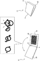
図6は、組み立てられた動画カード10と、生じる動画との関係を示している。表紙20と裏表紙40を相対回動させると、フィルムゲージ45に対して、下絵フラップ11が相対スライドする。これによって、視覚的効果を利用した動画が現れる。図6では、3つの画素から構成される動画の一例を示しているが、具体的な図柄や画素の数は、任意に設定することができる。
この動画カードを菓子のオマケとした場合、当該菓子あるいは製造メーカーと関連付けた動画を採用することで、宣伝効果あるいは販売促進効果を高めることができる。
FIG. 6 shows the relationship between the assembled
When this video card is used as a gift for confectionery, the advertising effect or the sales promotion effect can be enhanced by adopting a video associated with the confectionery or the manufacturer.
≪格子状のフィルムゲージ≫
本発明においては、ストライプ状のフィルムゲージ45に限らず、格子状のフィルムゲージ45’を採用することも可能である(図5中の円内)。勿論、その場合には、下絵26は、これに対応して動画を生じさせるものが採用される。
ストライプ状のフィルムゲージ45の場合、一方向の相対スライドによって動画が生じるが、格子状のフィルムゲージ45’の場合、タテ、ヨコ、ナナメのいずれの方向に相対スライドした場合でも動画が生じる。これは、動画カードの組み立て精度が高くなく、相対スライド方向が予定の一方向から逸れた場合でも動画に変化が生じるという点で有効である。
≪Lattice film gauge≫
In the present invention, not only the stripe-shaped
In the case of the stripe-shaped
≪下絵フラップとフィルムゲージとの密着性を高めるための構成:図7≫
下絵フラップ11とフィルムゲージ45を重ねて相対スライドさせることで動画を生じさせる場合、両者の隙間が大きいと、動画がボヤケて見えることがある。動画をクリアにするためには、下絵フラップ11とフィルムゲージ45を、適度に圧接させることが好ましい。
そのため、第1実施形態では、下絵フラップ(第1区画)11が、表紙20の内面において、連設線cから一定距離“L”だけオフセットした位置から立ち上がるよう構成している。すなわち、図7中に部分的に拡大して示したように、表紙20の内面から立ち上がる下絵フラップ11の根元11aは、連設線cから上方に距離“L”だけ離されている(オフセットされている)。これにより、下絵フラップ11をフィルムゲージ45に対して圧接させる力が生じる。つまり、下絵フラップ11とフィルムゲージ45が適度に密着して、クリアな動画を得ることができる。
≪Configuration for improving adhesion between background flap and film gauge: Fig. 7≫
When a moving image is generated by overlapping the
Therefore, in the first embodiment, the background flap (first section) 11 is configured to rise from a position offset from the continuous line c by a fixed distance “L” on the inner surface of the
≪第2実施形態:図8≫
次に図8を参照して、第2実施形態に係る動画カード10’を説明する。上に説明した第1実施形態と比較して、カードが透明シート基材で作られている点、およびフィルムゲージが当該透明シート基材に直接印刷されている点が異なる。以下、異なる点を中心に説明する。
<< Second Embodiment: FIG. 8 >>
Next, with reference to FIG. 8, a moving
動画カード10’を構成する透明シート基材は、折罫a、b、c、dを介して連設された5つの区画31〜35を含む。第5区画35にはゲージ45”が直接印刷されている。すなわち、透明シート基材上に、黒い棒状領域が間隔をおいて複数平行に印刷され、これがフィルムゲージ45”として機能する。
The transparent sheet base material constituting the moving
先に説明した第1実施形態では、紙基材の第5区画15に開口18を形成し、これを塞ぐように、別部材であるフィルムゲージ45を貼り付けていた。これでは、製造工程が複雑となって、コストアップを招く。そこで、第2実施形態では、透明シート基材に対してフィルムゲージを直接印刷することで、製造工程の簡単化を実現している。
In 1st Embodiment demonstrated previously, the
動画カード10’の第1区画31(下絵フラップ)には、複合画像26が表示される。複合画像26は、第1区画31上に直接印刷してもよいし、別のシート片に印刷したものを貼り付けてもよい。製造工程の簡単化という点では、直接印刷する方が好ましい。
The
透明シート基材の他の区画32、33、34に対しては、適宜の印刷、その他の装飾等を施してもよい。
Appropriate printing, other decorations, and the like may be applied to the
≪変形例:図9≫
図8に示した第2実施形態では、第5区画35の中央領域(すなわち、組立後に、下面側に位置する複合画像26が相対スライドする領域)にのみゲージが印刷されているが、少なくとも当該領域にゲージが存在すればよいから、例えば、透明シート基材の全面にゲージを印刷してもよい。そのような変形例を図9に示している。
この場合、複合画像26は、別のシート片38に印刷して、第1区画31(下絵フラップ)上に貼り付けることとなる。このように構成すると、透明シート基材上の特定の領域に限定してゲージを印刷する必要がなく、全面にゲージを印刷した透明シート基材を使用して動画カード10”を作成できるので、製造工程が簡単となる。
<Modification: FIG. 9>
In the second embodiment shown in FIG. 8, the gauge is printed only in the central area of the fifth section 35 (that is, the area where the
In this case, the
なお、図8、9に示した例においても、第1実施形態の場合と同様、格子状のゲージを採用してもよい。 In the examples shown in FIGS. 8 and 9, a lattice gauge may be adopted as in the case of the first embodiment.
10、10’、10” 動画カード
11、31 第1区画(下絵フラップ)
12、32 第2区画
13、33 第3区画
14、34 第4区画
15、35 第5区画
18 開口
20 表紙
26 複合画像
38 シート片
40 裏表紙
45、45’、45” フィルムゲージ
a、b、c、d 折罫
10, 10 ', 10 "
12, 32
Claims (4)
当該動画カードは、連設線(c)において相対回動可能に連設された表紙(20)と裏表紙(40)を備え、
表紙(20)または裏表紙(40)の一方の内面に下絵フラップ(11、31)が立設されるとともに、他方の内面にフィルムゲージ(45)が保持され、かつ、立設された下絵フラップ(11、31)は、フィルムゲージ(45)の下面側に差し込まれていて、
表紙(20)と裏表紙(40)を相対的に回動させると、これと連動して下絵フラップ(11、31)がフィルムゲージ(45)に対して相対的にスライドし、これにより上記動画が生じることを特徴とする、動画カード。 By overlaying the background flaps (11, 31) on which the background image composed of the composite image (26) is displayed and the film gauge (45) corresponding to the background image, and moving both relative to each other, the moving image is displayed. A video card to generate,
The moving picture card includes a front cover (20) and a back cover (40) which are continuously connected to each other on the continuous line (c).
A sketch flap (11, 31) is erected on one inner surface of the cover (20) or back cover (40), and a film gauge (45) is held on the other inner surface, and the erection flap is erected. (11, 31) is inserted on the lower surface side of the film gauge (45),
When the front cover (20) and the back cover (40) are relatively rotated, the background flaps (11, 31) are slid relative to the film gauge (45) in conjunction with this, whereby the moving image A video card characterized by
第3区画(33)と第4区画(34)との間の折罫が上記連設線(c)を構成し、
第4区画(34)上に折り畳まれた第5区画(35)にゲージ(45”)が直接印刷されて、これが上記フィルムゲージ(45)として機能し、
第3区画(33)上に折り畳まれた第2区画(32)に連設された第1区画(31)に複合画像(26)が表示され、当該第1区画(31)が、上記下絵フラップとして、第4区画(34)と第5区画(35)の間に差し込まれてなる、動画カード。 3. The transparent sheet substrate according to claim 1 or 2, comprising a first to fifth five sections (31, 32, 33, 34, 35) arranged in a line through a crease. Video card
The crease between the third section (33) and the fourth section (34) constitutes the continuous line (c),
A gauge (45 ″) is directly printed on the fifth section (35) folded on the fourth section (34), which functions as the film gauge (45),
The composite image (26) is displayed in the first section (31) connected to the second section (32) folded on the third section (33), and the first section (31) is the above-described background flap. As a video card, inserted between the fourth section (34) and the fifth section (35).
複合画像(26)は、別のシート片(38)に表示された上で、第1区画(31)上に設けられていることを特徴とする、請求項3記載の動画カード。 The gauge (45 ″) is printed on the entire surface of the transparent sheet substrate,
The moving picture card according to claim 3, wherein the composite image (26) is displayed on another sheet piece (38) and is provided on the first section (31).
Priority Applications (1)
| Application Number | Priority Date | Filing Date | Title |
|---|---|---|---|
| JP2008237656A JP5146213B2 (en) | 2008-09-17 | 2008-09-17 | Video card |
Applications Claiming Priority (1)
| Application Number | Priority Date | Filing Date | Title |
|---|---|---|---|
| JP2008237656A JP5146213B2 (en) | 2008-09-17 | 2008-09-17 | Video card |
Publications (2)
| Publication Number | Publication Date |
|---|---|
| JP2010072167A true JP2010072167A (en) | 2010-04-02 |
| JP5146213B2 JP5146213B2 (en) | 2013-02-20 |
Family
ID=42204030
Family Applications (1)
| Application Number | Title | Priority Date | Filing Date |
|---|---|---|---|
| JP2008237656A Expired - Fee Related JP5146213B2 (en) | 2008-09-17 | 2008-09-17 | Video card |
Country Status (1)
| Country | Link |
|---|---|
| JP (1) | JP5146213B2 (en) |
Cited By (5)
| Publication number | Priority date | Publication date | Assignee | Title |
|---|---|---|---|---|
| JP2010120364A (en) * | 2008-10-24 | 2010-06-03 | Dainippon Printing Co Ltd | Special signature for producing animation, and booklet equipped with the same |
| JP2010181772A (en) * | 2009-02-09 | 2010-08-19 | Toppan Printing Co Ltd | Variable image display body |
| JP2010181771A (en) * | 2009-02-09 | 2010-08-19 | Toppan Printing Co Ltd | Variable image display body |
| JP2014228843A (en) * | 2013-05-27 | 2014-12-08 | 凸版印刷株式会社 | Pattern variable display body and method of manufacturing pattern variable display body |
| JP2014226907A (en) * | 2013-05-27 | 2014-12-08 | 凸版印刷株式会社 | Pattern variable display booklet and method for manufacturing the same |
Citations (1)
| Publication number | Priority date | Publication date | Assignee | Title |
|---|---|---|---|---|
| JP2006208749A (en) * | 2005-01-28 | 2006-08-10 | Keystone & Associates Kk | Automatic animation display apparatus |
-
2008
- 2008-09-17 JP JP2008237656A patent/JP5146213B2/en not_active Expired - Fee Related
Patent Citations (1)
| Publication number | Priority date | Publication date | Assignee | Title |
|---|---|---|---|---|
| JP2006208749A (en) * | 2005-01-28 | 2006-08-10 | Keystone & Associates Kk | Automatic animation display apparatus |
Cited By (5)
| Publication number | Priority date | Publication date | Assignee | Title |
|---|---|---|---|---|
| JP2010120364A (en) * | 2008-10-24 | 2010-06-03 | Dainippon Printing Co Ltd | Special signature for producing animation, and booklet equipped with the same |
| JP2010181772A (en) * | 2009-02-09 | 2010-08-19 | Toppan Printing Co Ltd | Variable image display body |
| JP2010181771A (en) * | 2009-02-09 | 2010-08-19 | Toppan Printing Co Ltd | Variable image display body |
| JP2014228843A (en) * | 2013-05-27 | 2014-12-08 | 凸版印刷株式会社 | Pattern variable display body and method of manufacturing pattern variable display body |
| JP2014226907A (en) * | 2013-05-27 | 2014-12-08 | 凸版印刷株式会社 | Pattern variable display booklet and method for manufacturing the same |
Also Published As
| Publication number | Publication date |
|---|---|
| JP5146213B2 (en) | 2013-02-20 |
Similar Documents
| Publication | Publication Date | Title |
|---|---|---|
| JP5146213B2 (en) | Video card | |
| CN103440822A (en) | Transparent display and transparent display panel | |
| RU2568564C2 (en) | Food package | |
| JP5239557B2 (en) | Packaging box | |
| JP5223569B2 (en) | Booklet with decorative elements that produce a video | |
| JP5304056B2 (en) | Packaging box | |
| KR20010014343A (en) | System for the continuous application of publicity in a visualising device animated sequentially or continuously | |
| JP5338158B2 (en) | Free sample package | |
| JP5239558B2 (en) | Packaging box | |
| JP5169692B2 (en) | Special signatures that produce movies, and booklets with them | |
| CN207216172U (en) | A kind of grating cartoon apparatus for demonstrating | |
| JP5218010B2 (en) | Special signatures that produce movies, and booklets with them | |
| JP6269039B2 (en) | Variable image display body and method of manufacturing variable image display body | |
| JP5928996B2 (en) | Variable image display | |
| JP3155265U (en) | Display board | |
| US1157915A (en) | Picture-frame. | |
| JP2004062025A (en) | Stereoscopic projection device, screen used for the same, and projection method | |
| KR200187780Y1 (en) | Three-dimensional picture | |
| JP6277306B1 (en) | Packaging container | |
| CN107505718A (en) | A kind of grating cartoon apparatus for demonstrating and preparation method thereof | |
| JP3180190U (en) | Sliding image display | |
| JP3203258U (en) | Picture change sheet that can change combination of images and 4-frame video | |
| ES2423104B1 (en) | PROCEDURE OF FORMATION OF IMAGES OR LEGENDS FOR OVERLAY | |
| JP2506177Y2 (en) | Calculation card tool | |
| JP2022122859A (en) | flat article |
Legal Events
| Date | Code | Title | Description |
|---|---|---|---|
| A621 | Written request for application examination |
Free format text: JAPANESE INTERMEDIATE CODE: A621 Effective date: 20110616 |
|
| A977 | Report on retrieval |
Free format text: JAPANESE INTERMEDIATE CODE: A971007 Effective date: 20120731 |
|
| A131 | Notification of reasons for refusal |
Free format text: JAPANESE INTERMEDIATE CODE: A131 Effective date: 20120807 |
|
| A521 | Written amendment |
Free format text: JAPANESE INTERMEDIATE CODE: A523 Effective date: 20121002 |
|
| TRDD | Decision of grant or rejection written | ||
| A01 | Written decision to grant a patent or to grant a registration (utility model) |
Free format text: JAPANESE INTERMEDIATE CODE: A01 Effective date: 20121030 |
|
| A61 | First payment of annual fees (during grant procedure) |
Free format text: JAPANESE INTERMEDIATE CODE: A61 Effective date: 20121112 |
|
| R150 | Certificate of patent or registration of utility model |
Ref document number: 5146213 Country of ref document: JP Free format text: JAPANESE INTERMEDIATE CODE: R150 Free format text: JAPANESE INTERMEDIATE CODE: R150 |
|
| FPAY | Renewal fee payment (event date is renewal date of database) |
Free format text: PAYMENT UNTIL: 20151207 Year of fee payment: 3 |
|
| LAPS | Cancellation because of no payment of annual fees |