JP2010070440A - Arc discharge method, arc discharge apparatus, and quartz glass crucible manufacturing apparatus - Google Patents
Arc discharge method, arc discharge apparatus, and quartz glass crucible manufacturing apparatus Download PDFInfo
- Publication number
- JP2010070440A JP2010070440A JP2008242874A JP2008242874A JP2010070440A JP 2010070440 A JP2010070440 A JP 2010070440A JP 2008242874 A JP2008242874 A JP 2008242874A JP 2008242874 A JP2008242874 A JP 2008242874A JP 2010070440 A JP2010070440 A JP 2010070440A
- Authority
- JP
- Japan
- Prior art keywords
- electrode
- arc discharge
- carbon
- diameter
- carbon electrode
- Prior art date
- Legal status (The legal status is an assumption and is not a legal conclusion. Google has not performed a legal analysis and makes no representation as to the accuracy of the status listed.)
- Granted
Links
- 238000010891 electric arc Methods 0.000 title claims abstract description 81
- VYPSYNLAJGMNEJ-UHFFFAOYSA-N Silicium dioxide Chemical compound O=[Si]=O VYPSYNLAJGMNEJ-UHFFFAOYSA-N 0.000 title claims abstract description 64
- 238000004519 manufacturing process Methods 0.000 title claims abstract description 23
- 238000001241 arc-discharge method Methods 0.000 title claims abstract description 16
- OKTJSMMVPCPJKN-UHFFFAOYSA-N Carbon Chemical compound [C] OKTJSMMVPCPJKN-UHFFFAOYSA-N 0.000 claims abstract description 99
- 229910052799 carbon Inorganic materials 0.000 claims abstract description 99
- VNWKTOKETHGBQD-UHFFFAOYSA-N methane Chemical compound C VNWKTOKETHGBQD-UHFFFAOYSA-N 0.000 claims abstract description 34
- 238000002844 melting Methods 0.000 claims abstract description 30
- 230000008018 melting Effects 0.000 claims abstract description 30
- 238000000034 method Methods 0.000 claims abstract description 14
- 238000010438 heat treatment Methods 0.000 claims abstract description 10
- 239000000843 powder Substances 0.000 claims description 33
- 239000002994 raw material Substances 0.000 claims description 7
- 238000000465 moulding Methods 0.000 claims description 3
- 239000013078 crystal Substances 0.000 abstract description 5
- 230000010355 oscillation Effects 0.000 abstract description 2
- 230000003044 adaptive effect Effects 0.000 abstract 1
- 229910052710 silicon Inorganic materials 0.000 abstract 1
- 239000010703 silicon Substances 0.000 abstract 1
- 239000010453 quartz Substances 0.000 description 27
- 238000004070 electrodeposition Methods 0.000 description 9
- 230000008859 change Effects 0.000 description 5
- 238000010586 diagram Methods 0.000 description 5
- 230000002093 peripheral effect Effects 0.000 description 5
- 230000007423 decrease Effects 0.000 description 4
- 230000007246 mechanism Effects 0.000 description 4
- 230000000694 effects Effects 0.000 description 3
- 238000010309 melting process Methods 0.000 description 3
- XEEYBQQBJWHFJM-UHFFFAOYSA-N Iron Chemical compound [Fe] XEEYBQQBJWHFJM-UHFFFAOYSA-N 0.000 description 2
- 230000006837 decompression Effects 0.000 description 2
- 238000000151 deposition Methods 0.000 description 2
- 230000008021 deposition Effects 0.000 description 2
- 238000009826 distribution Methods 0.000 description 2
- 239000002245 particle Substances 0.000 description 2
- 230000002265 prevention Effects 0.000 description 2
- 230000018199 S phase Effects 0.000 description 1
- 230000002411 adverse Effects 0.000 description 1
- 230000000052 comparative effect Effects 0.000 description 1
- 239000004020 conductor Substances 0.000 description 1
- 238000012217 deletion Methods 0.000 description 1
- 230000037430 deletion Effects 0.000 description 1
- 230000001687 destabilization Effects 0.000 description 1
- 230000006866 deterioration Effects 0.000 description 1
- 230000002542 deteriorative effect Effects 0.000 description 1
- 230000005684 electric field Effects 0.000 description 1
- 230000002143 encouraging effect Effects 0.000 description 1
- 238000005516 engineering process Methods 0.000 description 1
- 239000005350 fused silica glass Substances 0.000 description 1
- 239000011521 glass Substances 0.000 description 1
- 125000002887 hydroxy group Chemical group [H]O* 0.000 description 1
- 230000006872 improvement Effects 0.000 description 1
- 239000012535 impurity Substances 0.000 description 1
- 230000003993 interaction Effects 0.000 description 1
- 229910052742 iron Inorganic materials 0.000 description 1
- 239000000463 material Substances 0.000 description 1
- 239000000155 melt Substances 0.000 description 1
- 239000000203 mixture Substances 0.000 description 1
- 229910021421 monocrystalline silicon Inorganic materials 0.000 description 1
- 238000009828 non-uniform distribution Methods 0.000 description 1
- 239000000615 nonconductor Substances 0.000 description 1
- 238000010248 power generation Methods 0.000 description 1
- 230000008569 process Effects 0.000 description 1
- 239000004065 semiconductor Substances 0.000 description 1
- 238000007751 thermal spraying Methods 0.000 description 1
- 238000004017 vitrification Methods 0.000 description 1
- 235000012431 wafers Nutrition 0.000 description 1
Images


Classifications
-
- H—ELECTRICITY
- H05—ELECTRIC TECHNIQUES NOT OTHERWISE PROVIDED FOR
- H05B—ELECTRIC HEATING; ELECTRIC LIGHT SOURCES NOT OTHERWISE PROVIDED FOR; CIRCUIT ARRANGEMENTS FOR ELECTRIC LIGHT SOURCES, IN GENERAL
- H05B7/00—Heating by electric discharge
- H05B7/02—Details
- H05B7/06—Electrodes
- H05B7/08—Electrodes non-consumable
- H05B7/085—Electrodes non-consumable mainly consisting of carbon
-
- C—CHEMISTRY; METALLURGY
- C03—GLASS; MINERAL OR SLAG WOOL
- C03B—MANUFACTURE, SHAPING, OR SUPPLEMENTARY PROCESSES
- C03B20/00—Processes specially adapted for the production of quartz or fused silica articles, not otherwise provided for
-
- C—CHEMISTRY; METALLURGY
- C03—GLASS; MINERAL OR SLAG WOOL
- C03B—MANUFACTURE, SHAPING, OR SUPPLEMENTARY PROCESSES
- C03B19/00—Other methods of shaping glass
- C03B19/09—Other methods of shaping glass by fusing powdered glass in a shaping mould
- C03B19/095—Other methods of shaping glass by fusing powdered glass in a shaping mould by centrifuging, e.g. arc discharge in rotating mould
-
- C—CHEMISTRY; METALLURGY
- C04—CEMENTS; CONCRETE; ARTIFICIAL STONE; CERAMICS; REFRACTORIES
- C04B—LIME, MAGNESIA; SLAG; CEMENTS; COMPOSITIONS THEREOF, e.g. MORTARS, CONCRETE OR LIKE BUILDING MATERIALS; ARTIFICIAL STONE; CERAMICS; REFRACTORIES; TREATMENT OF NATURAL STONE
- C04B35/00—Shaped ceramic products characterised by their composition; Ceramics compositions; Processing powders of inorganic compounds preparatory to the manufacturing of ceramic products
- C04B35/515—Shaped ceramic products characterised by their composition; Ceramics compositions; Processing powders of inorganic compounds preparatory to the manufacturing of ceramic products based on non-oxide ceramics
- C04B35/52—Shaped ceramic products characterised by their composition; Ceramics compositions; Processing powders of inorganic compounds preparatory to the manufacturing of ceramic products based on non-oxide ceramics based on carbon, e.g. graphite
-
- C—CHEMISTRY; METALLURGY
- C30—CRYSTAL GROWTH
- C30B—SINGLE-CRYSTAL GROWTH; UNIDIRECTIONAL SOLIDIFICATION OF EUTECTIC MATERIAL OR UNIDIRECTIONAL DEMIXING OF EUTECTOID MATERIAL; REFINING BY ZONE-MELTING OF MATERIAL; PRODUCTION OF A HOMOGENEOUS POLYCRYSTALLINE MATERIAL WITH DEFINED STRUCTURE; SINGLE CRYSTALS OR HOMOGENEOUS POLYCRYSTALLINE MATERIAL WITH DEFINED STRUCTURE; AFTER-TREATMENT OF SINGLE CRYSTALS OR A HOMOGENEOUS POLYCRYSTALLINE MATERIAL WITH DEFINED STRUCTURE; APPARATUS THEREFOR
- C30B15/00—Single-crystal growth by pulling from a melt, e.g. Czochralski method
- C30B15/10—Crucibles or containers for supporting the melt
Landscapes
- Engineering & Computer Science (AREA)
- Chemical & Material Sciences (AREA)
- Organic Chemistry (AREA)
- Materials Engineering (AREA)
- Manufacturing & Machinery (AREA)
- Ceramic Engineering (AREA)
- Physics & Mathematics (AREA)
- Plasma & Fusion (AREA)
- Metallurgy (AREA)
- Crystallography & Structural Chemistry (AREA)
- Structural Engineering (AREA)
- Glass Melting And Manufacturing (AREA)
- Discharge Heating (AREA)
- Crystals, And After-Treatments Of Crystals (AREA)
- Crucibles And Fluidized-Bed Furnaces (AREA)
Abstract
Description
本発明は、アーク放電方法、アーク放電装置、石英ガラスルツボ製造装置に係り、特に、アーク放電によって石英粉を加熱溶融してガラス化する際に、アーク放電時の電極振動の防止に用いて好適な技術に関する。 The present invention relates to an arc discharge method, an arc discharge apparatus, and a quartz glass crucible manufacturing apparatus, and is particularly suitable for use in preventing electrode vibration during arc discharge when the quartz powder is heated and melted into glass by arc discharge. Technology.
単結晶シリコンの引き上げに用いる石英ガラスルツボは主にアーク溶融法によって製造されている。この方法の概略は、カーボン製モールドの内表面に石英粉を一定厚さに堆積し、この石英堆積層の上方に炭素電極を設置し、そのアーク放電によって石英堆積層を加熱し、ガラス化して石英ガラスルツボを製造する方法である。 Quartz glass crucibles used for pulling single crystal silicon are mainly manufactured by the arc melting method. The outline of this method is that quartz powder is deposited on the inner surface of a carbon mold to a certain thickness, a carbon electrode is placed above the quartz deposition layer, the quartz deposition layer is heated by virtue of arc discharge, and vitrified. A method for producing a quartz glass crucible.
特許文献1にはアーク溶融による石英ガラスルツボ製造におけるアーク溶融に関する技術が記載され、特許文献2にはアーク放電における電極に関する技術が記載されている。
また、近年デバイス工程の効率化等の要請から、製造するウェーハ口径が300mmを超える程度と大きくなっており、これに伴って大口径の単結晶を引き上げ可能な石英ガラスルツボが要求されている。また、デバイスの微細化等の要請から、引き上げる単結晶の特性に直接影響を与える石英ガラスルツボ内面状態等のルツボ特性の向上にも、強い要求がある。
しかし、30インチ〜40インチといった大口径の石英ガラスルツボを製造する際には、石英粉を溶融するために必要な電力量が増大し、これに伴って、アーク放電開始時に発生する電極の震動が無視し得ないものになってきた。
このようにアーク放電開始時に電極震動が発生した場合、これに伴って、アーク中を流れる電流が変化し、この電流変化によってさらに電極を振動させ、結果的に発生した電極振動の振幅が大きくなる。その結果、発生するアークが不安定になり、溶融する石英粉状態に与える無視できなくなるという問題がある。さらに、電極振動が大きくなった場合、振動により電極から発生した微少片が落下して石英ガラスルツボ特性が悪化するという問題があった。また、電極振動の振幅が増大した場合には電極が破損する可能性があるという問題があった。
However, when manufacturing a quartz glass crucible with a large diameter of 30 inches to 40 inches, the amount of electric power required to melt the quartz powder increases, and accompanying this, the vibration of the electrode generated at the start of arc discharge. Has become something that cannot be ignored.
Thus, when an electrode vibration occurs at the start of arc discharge, the current flowing in the arc changes accordingly, and this current change further vibrates the electrode, resulting in an increase in the amplitude of the generated electrode vibration. . As a result, the generated arc becomes unstable, and there is a problem that it cannot be ignored given to the molten quartz powder state. Further, when the electrode vibration becomes large, there is a problem that a minute piece generated from the electrode is dropped by the vibration and the quartz glass crucible characteristic is deteriorated. Further, there is a problem that the electrode may be damaged when the amplitude of the electrode vibration increases.
電極の振動を防止するためには、電極を高強度の材料に変更する、電極径を拡大する等、電極強度を増すことが考えられる。しかし、石英ガラスルツボ製造におけるアーク放電電極は、この電極自体が消耗してその組成が石英粉溶融雰囲気に放出されるため、ルツボ特性に与える影響から炭素電極以外のものは使用できない。また、電極径を拡大した場合には電力密度が低下し、アーク出力が不安定になりルツボ特性に悪影響を与える可能性がある。
なお、このような電極振動による影響はルツボ口径の増大に伴うアーク溶融の出力増大によって初めて発生したものである。
In order to prevent the vibration of the electrode, it is conceivable to increase the electrode strength such as changing the electrode to a high-strength material or expanding the electrode diameter. However, as the arc discharge electrode in the production of the quartz glass crucible, since the electrode itself is consumed and the composition is released into the quartz powder melting atmosphere, other than the carbon electrode cannot be used due to the influence on the crucible characteristics. Further, when the electrode diameter is enlarged, the power density is lowered, and the arc output becomes unstable, which may adversely affect the crucible characteristics.
Note that the influence of such electrode vibrations is first caused by an increase in arc melting output accompanying an increase in the crucible diameter.
本発明は、上記の事情に鑑みてなされたもので、以下の目的を達成しようとするものである。
1.電極振動の発生を防止すること。
2.アークの安定化を図ること。
3.ルツボ特性の悪化を防止し、その向上を図ること。
4.大出力アーク溶融に対応可能な方法および装置を提供すること。
The present invention has been made in view of the above circumstances, and intends to achieve the following object.
1. Prevent electrode vibrations from occurring.
2. Stabilize the arc.
3. To prevent and improve the crucible characteristics.
4). To provide a method and apparatus capable of handling high-power arc melting.
本発明の本発明のアーク放電方法は、300kVA〜12,000kVAの出力範囲で、複数の炭素電極によりアーク放電によって非導電性対象物を加熱溶融する方法であって、
アーク放電開始時に前記炭素電極どうしを接触させる接触位置と先端との距離が前記炭素電極径に対する比率として0〜0.9の範囲となるよう設定することにより上記課題を解決した。
本発明本発明において、前記炭素電極における電力密度を40kVA/cm2 〜1,700kVA/cm2に設定することがより好ましい。
本発明本発明のアーク放電装置は、300kVA〜12,000kVAの出力範囲で、複数の炭素電極によりアーク放電によって非導電性対象物を加熱溶融する装置であって、
前記炭素電極どうしを接触させる接触位置と先端との距離が前記炭素電極径に対する比率として0.001〜0.9の範囲となるよう前記炭素電極が配置されてなることにより上記課題を解決した。
また、また、本発明において、前記炭素電極における電力密度が40kVA/cm2 〜1,700kVA/cm2に設定されてなることができる。
また、また、前記炭素電極には、前記接触位置を含む接触部分が先端に設けられ、該接触部分の形状が、先端に向かって縮径する円錐、円錐台、または、該炭素電極の軸線に沿った断面輪郭において曲率不連続点が存在しない曲線となる形状とされてなる手段を採用することもできる。
本発明本発明においては、前記炭素電極は、その径寸法とアーク放電単位分当たりに消耗する長さ寸法との比が0.02〜0.6の範囲となるよう設定されてなることが望ましい。
本発明の石英ガラスルツボ製造装置は、原料粉末をルツボ成形用のモールド内に成形し、その成形体をアーク放電によって加熱溶融して石英ガラスルツボを製造する装置であって、
原料粉を充填して成形するモールドと、上記のいずれか記載のアーク放電装置をとを有してなることを特徴とすることができる。
The arc discharge method of the present invention is a method for heating and melting a non-conductive object by arc discharge with a plurality of carbon electrodes in an output range of 300 kVA to 12,000 kVA,
The said subject was solved by setting so that the distance of the contact position which contacts the said carbon electrodes at the time of arc discharge start, and a front-end | tip may become the range of 0-0.9 as a ratio with respect to the said carbon electrode diameter.
In the present invention the present invention, it is more preferable to set the power density of the carbon electrode to 40kVA / cm 2 ~1,700kVA / cm 2 .
The arc discharge apparatus of the present invention is an apparatus for heating and melting a non-conductive object by arc discharge with a plurality of carbon electrodes in an output range of 300 kVA to 12,000 kVA,
The said subject was solved by arrange | positioning the said carbon electrode so that the distance of the contact position which contacts the said carbon electrodes, and the front-end | tip may become the range of 0.001-0.9 as a ratio with respect to the said carbon electrode diameter.
Further, also in the present invention, the power density of the carbon electrode can be set to 40kVA / cm 2 ~1,700kVA / cm 2 .
Further, the carbon electrode is provided with a contact portion including the contact position at the tip, and the shape of the contact portion is a cone, a truncated cone, or an axis of the carbon electrode whose diameter decreases toward the tip. It is also possible to adopt a means having a shape that forms a curve with no discontinuity of curvature in the cross-sectional contour along.
In the present invention, it is desirable that the carbon electrode is set so that the ratio of the diameter dimension to the length dimension consumed per unit of arc discharge is in the range of 0.02 to 0.6. .
The silica glass crucible manufacturing apparatus of the present invention is an apparatus for manufacturing a silica glass crucible by forming raw material powder in a mold for crucible molding and heating and melting the molded body by arc discharge.
It can be characterized by having a mold that is filled and molded with raw material powder and the arc discharge device described above.
本発明の本発明のアーク放電方法は、300kVA〜12,000kVAの出力範囲で、複数の炭素電極によりアーク放電によって非導電性対象物(石英粉)を加熱溶融する方法であって、
アーク放電開始時に前記炭素電極どうしを接触させる接触位置と先端との距離が前記炭素電極径に対する比率として0〜0.9の範囲となるよう設定することで、アーク放電時に発生する電極震動の振幅が電極直径の0.15倍より大きくなることを防止して、たとえ電極振動が発生してもそれ以上拡大せずに収束し、電極振動が収まって安定したアークを発生させることが可能となる。
The arc discharge method of the present invention is a method of heating and melting a non-conductive object (quartz powder) by arc discharge with a plurality of carbon electrodes in an output range of 300 kVA to 12,000 kVA,
By setting the distance between the contact position where the carbon electrodes are brought into contact with each other at the start of arc discharge and the tip to be in the range of 0 to 0.9 as the ratio to the carbon electrode diameter, the amplitude of electrode vibration generated during arc discharge Can be prevented from becoming larger than 0.15 times the electrode diameter, and even if electrode vibration occurs, it converges without further expansion, and it becomes possible to generate a stable arc by converging the electrode vibration. .
本発明者らは、アーク溶融の状態悪化が発生する程度の電極振動が発生するメカニズムを次のように考察した。 The inventors of the present invention have considered the mechanism of the occurrence of electrode vibration to the extent that deterioration of the state of arc melting occurs as follows.
アーク放電中に炭素電極で微少振動が発生した場合、この振動による電極位置変動によって、供給している電流にも変動が生ずる。さらに、発生した電流の微少振動によって、電極にローレンツ力が作用し、電極振動の振幅が増大する。電極振動の振幅が増大すると、電流の振動もさらに増大する。このような助長効果により、電極振動が増大し続け、結果的に電極破損に至るほど電極振動がおおきくなる可能性がある。 When a minute vibration is generated at the carbon electrode during arc discharge, the supplied current also varies due to the electrode position variation caused by the vibration. Furthermore, the Lorentz force acts on the electrode due to the minute vibration of the generated current, and the amplitude of the electrode vibration increases. As the amplitude of the electrode vibration increases, the current vibration further increases. Due to such an encouraging effect, the electrode vibration continues to increase, and as a result, the electrode vibration may increase as the electrode breaks.
しかし、本発明者らは、アーク放電中に炭素電極で発生した振動の振幅が電極直径の0.15倍以下に押さえられた場合には、この電極振動と、電極振動によって発生する電流変動との相互作用で電極振動が増大する現象を防止して、振動を収束させることが可能であることを見出した。このような振幅範囲であれば、電極振動が発生した場合でも、電流変化および電極振動に起因するローレンツ力が大きくなることを防止して、電極振動が大きくなることを防止できると考えられる。
これに対し、アーク放電中に炭素電極で発生した振動の振幅が電極直径の0.15倍より大きい場合には、電極振動が増大し続け、結果的に電極破損に至る可能性がある。従って、電極振動振幅を上記の範囲に収めるよう、振動発生時におけるローレンツ力の許容限界を制御するために、以下のように設定したものである。
However, when the amplitude of the vibration generated at the carbon electrode during the arc discharge is suppressed to 0.15 times or less of the electrode diameter, the inventors have found that this electrode vibration and the current fluctuation generated by the electrode vibration It has been found that it is possible to converge the vibration by preventing the phenomenon that the electrode vibration increases due to the interaction. In such an amplitude range, even when electrode vibration occurs, it is considered that the Lorentz force due to the current change and the electrode vibration can be prevented from increasing, and the electrode vibration can be prevented from increasing.
On the other hand, when the amplitude of the vibration generated at the carbon electrode during the arc discharge is larger than 0.15 times the electrode diameter, the electrode vibration continues to increase, which may result in electrode breakage. Therefore, in order to control the allowable limit of the Lorentz force at the time of vibration generation so as to keep the electrode vibration amplitude within the above range, the following is set.
また、石英ガラスルツボ製造のように非導電性対象物をアーク溶融する場合には、鉄等の導電性物質をアーク溶融する場合と異なり、電極間で放電開始をおこなわなくてはいけないため、電極先端を収束しておくことが必要となり放電方向が電極の軸線と交わる方向となるため、電極振動が発生しやすい。さらに、石英ガラスルツボ製造のように単に対象物を溶融すればよい状況と異なり、被溶融物である石英粉末成形体表面付近の温度状態管理を精密におこなう必要があるため、電極の位置状態等をよりいっそう正確に制御することが要求されることになる。 Also, when arc melting non-conductive objects as in quartz glass crucible production, unlike arc melting of conductive materials such as iron, it is necessary to start discharge between the electrodes. It is necessary to converge the tip, and the discharge direction is a direction intersecting with the axis of the electrode, so that electrode vibration is likely to occur. Furthermore, unlike the situation in which the object only needs to be melted as in the production of a quartz glass crucible, it is necessary to precisely control the temperature state in the vicinity of the surface of the quartz powder compact to be melted. It will be required to control more accurately.
本発明本発明において、前記炭素電極における電力密度を40kVA/cm2〜900kVA/cm2〜1,700kVA/cm2に設定することで、電極振動の増大原因となるローレンツ力を振動増大防止許容範囲内におさめることが可能となるため、発生した電極振動を収束させることが可能となるという効果を奏することができる。 In the present invention the present invention, the power density at the carbon electrode by setting the 40kVA / cm 2 ~900kVA / cm 2 ~1,700kVA / cm 2, increasing oscillating prevent tolerance to increase causative Lorentz force of the electrode vibrations Therefore, it is possible to converge the generated electrode vibration.
本発明において、電力密度とは、電極において、電極中心軸に直交する電極断面における単位断面積あたり供給される電力量を意味するものである。具体的には、電極先端から軸方向長さ15〜25mm程度、好ましくは20mmの位置において電極中心軸に直交する電極の断面積に対する1本の電極に供給する電力の比
供給電力量(kVA)/電極断面積(cm2 )
で表され、具体的には、20mmの位置における電極径寸法としてはφ20〜40mm、好ましくはφ25〜35mm、より好ましくはφ30mmとして上記の範囲を設定することができる。
In the present invention, the power density means the amount of power supplied per unit cross-sectional area in the electrode cross section orthogonal to the electrode central axis. Specifically, the ratio of the power supplied to one electrode with respect to the cross-sectional area of the electrode orthogonal to the electrode central axis at a position about 15 to 25 mm in the axial direction from the tip of the electrode, preferably 20 mm. Supply power amount (kVA) / Electrode cross-sectional area (cm 2 )
Specifically, the above-mentioned range can be set as φ20 to 40 mm, preferably φ25 to 35 mm, more preferably φ30 mm as the electrode diameter size at a position of 20 mm.
また、電極振動はアーク放電開始時に発生する可能性が最も高く、アーク溶融を開始する時点、すなわち、非導電性対象物(石英粉)への影響が高い温度上昇開始時における影響を抑えて、良好なアーク溶融をおこなうことが可能となる。 In addition, electrode vibration is most likely to occur at the start of arc discharge, suppressing the influence at the time of starting arc melting, that is, at the start of temperature rise that has a high effect on non-conductive objects (quartz powder), It becomes possible to perform good arc melting.
本発明本発明のアーク放電装置は、300kVA〜12,000kVAの出力範囲で、複数の炭素電極によりアーク放電によって非導電性対象物(石英粉)を加熱溶融する装置であって、
前記炭素電極どうしを接触させる接触位置と先端との距離が前記炭素電極径に対する比率として0〜0.9の範囲となるよう前記炭素電極が配置されてなることにより、24インチ以上の石英ガラスルツボの製造時に熱源として使用する高出力のアーク放電装置において、アーク放電時に発生する電極震動の振幅が電極直径の0.15倍より大きくなることを防止して、たとえ電極振動が発生してもそれ以上拡大せずに収束し、石英ガラスルツボの品質に影響を与える電極振動の拡大を防止して、安定したアークを発生させ、製造する石英ガラスルツボの品質を向上することが可能となる。
出力範囲が、上記の範囲より小さいとアークが継続しない可能性があるため好ましくなく、上記の範囲より大きいとコストがかかる過ぎるため好ましくない。また、接触位置と先端との距離が前記炭素電極径に対する比率が上記の範囲以外だと電極振動を防止できないため好ましくない。また、電極どうしを先端で接触させた場合に電極形状から電極軸線どうしの角度が好ましい範囲とならない場合には、接触位置と先端との距離が前記炭素電極径に対する比率を0.001〜0.9の範囲とすることができる。なお、上記の範囲における接触位置と電極先端との距離は、50mm以下0mm以上、より好ましくは20mm以下0mm以上であれば良好なアーク発生をおこなうことができる。
The present invention arc discharge device is an apparatus for heating and melting a non-conductive object (quartz powder) by arc discharge with a plurality of carbon electrodes in an output range of 300 kVA to 12,000 kVA,
By arranging the carbon electrode such that the distance between the contact position where the carbon electrodes are brought into contact with each other and the tip thereof is in the range of 0 to 0.9 as a ratio to the diameter of the carbon electrode, a quartz glass crucible of 24 inches or more is obtained. In a high-power arc discharge device used as a heat source during the manufacture of the electrode, the amplitude of electrode vibration generated during arc discharge is prevented from exceeding 0.15 times the electrode diameter, even if electrode vibration occurs. It is possible to improve the quality of the quartz glass crucible to be manufactured by generating a stable arc by preventing the expansion of electrode vibrations that converge without expanding and affect the quality of the quartz glass crucible.
If the output range is smaller than the above range, the arc may not continue, which is not preferable. If the output range is larger than the above range, it is not preferable because the cost is excessive. Further, if the ratio of the distance between the contact position and the tip to the carbon electrode diameter is outside the above range, electrode vibration cannot be prevented, which is not preferable. In addition, when the electrodes are brought into contact with each other at the tips, if the angle between the electrode axes does not fall within a preferable range due to the electrode shape, the distance between the contact position and the tip is a ratio of 0.001 to. A range of 9 can be used. In addition, if the distance between the contact position and the electrode tip in the above range is 50 mm or less and 0 mm or more, more preferably 20 mm or less and 0 mm or more, a good arc can be generated.
ここで、上述した電極振動が製造する石英ガラスルツボに及ぼす影響は、従来、22インチ程度までの小口径のルツボ製造においては認識されていなかったが、本発明者らはこれらを詳細に検討した結果、従来問題とされていなかった程度のルツボ特性として内表面状態のムラ発生がこの電極振動に起因する場合があることを突き止めた。従って、この電極振動発生を防止することで、製造する石英ガラスルツボ内表面特性の向上を図ることができる。 Here, the influence of the above-described electrode vibration on the quartz glass crucible to be manufactured has not been recognized conventionally in the manufacture of crucibles having a small diameter of up to about 22 inches, but the present inventors have studied these in detail. As a result, the present inventors have found out that unevenness of the inner surface state may be caused by this electrode vibration as a crucible characteristic that has not been regarded as a problem in the past. Therefore, by preventing the electrode vibration from occurring, the surface characteristics of the quartz glass crucible to be manufactured can be improved.
また、また、本発明において、前記炭素電極における電力密度が40kVA/cm2 〜1,700kVA/cm2に設定されてなることにより、電極振動の増大原因となるローレンツ力を振動増大防止許容範囲内におさめることが可能となるため、発生した電極振動を収束させることが可能となるという効果を奏することができる。この際、電力密度が上記の範囲より小さいとアークが継続しないため好ましくなく、上記の範囲より大きいと、電極振動の振幅が電極径の0.15より大きくなり、電極振動が増強し、アーク放電が停止するため好ましくない。 Further, also in the present invention, the by power density is set to 40kVA / cm 2 ~1,700kVA / cm 2 in the carbon electrode, the vibration increases prevent tolerance to increase causative Lorentz force of the electrode vibrations Since it can be suppressed, it is possible to bring about an effect that the generated electrode vibration can be converged. At this time, if the power density is smaller than the above range, it is not preferable because the arc does not continue. If larger than the above range, the amplitude of the electrode vibration becomes larger than 0.15 of the electrode diameter, the electrode vibration is enhanced, and Is not preferable because it stops.
また、また、前記炭素電極には、前記接触位置を含む接触部分が先端に設けられ、該接触部分の形状が、先端に向かって縮径する円錐、円錐台、または、該炭素電極の軸線に沿った断面輪郭において曲率不連続点が存在しない曲線となる形状とされてなることができ、具体的には、炭素電極は円柱棒状体とされて、その先端には、先端に向かって縮径する接触部分を有し、該接触部分は他の電極に接触した場合に1カ所で接触するよう、凹んだ部分がない形状とされている。つまり、この接触部分においては、電極どうしが2カ所以上で接触しないように、他の1つの電極との再近接距離を有する部分が、一点、または、1つの線状部分、あるいは1つの面状となる1カ所のみである形状とされている。また、炭素電極は、根本から先端へ向けてその全長にわたって縮径する形状とすることも可能である。
前記炭素電極は、複数本設けられ、それぞれが先端の接触部分のみで、接触可能に設けられている。具体的には、それぞれの炭素電極の先端が頂点を形成するように電極の本数に応じた多角錐の稜線となる状態に配置されることができる。また、電極先端の接触部分は、アーク放電を容易にし、かつ、電極振動を防止するために、先端に向けて縮径されている。これにより、電極振動の発生しやすい電極側面での放電を防止することができ、電極先端部分である凹みのない接触部分からのみ放電をおこなって、安定したアーク火炎の発生と電極振動の防止とを同時に実現することが可能となる。
Further, the carbon electrode is provided with a contact portion including the contact position at the tip, and the shape of the contact portion is a cone, a truncated cone, or an axis of the carbon electrode whose diameter decreases toward the tip. In the cross-sectional contour along, the shape can be a curve that does not have a discontinuity of curvature. Specifically, the carbon electrode is a cylindrical rod-like body, and the diameter of the carbon electrode is reduced toward the tip. The contact portion is configured to have no recessed portion so that the contact portion comes into contact with one electrode when it comes into contact with another electrode. That is, in this contact portion, a portion having a re-proximity distance with one other electrode is one point, one linear portion, or one planar shape so that the electrodes do not contact at two or more locations. It is the shape which is only one place. In addition, the carbon electrode can have a shape that decreases in diameter over the entire length from the root to the tip.
A plurality of the carbon electrodes are provided, and each of the carbon electrodes is provided so as to be in contact with only a contact portion at the tip. Specifically, it can arrange | position in the state used as the ridgeline of the polygonal pyramid according to the number of electrodes so that the front-end | tip of each carbon electrode may form a vertex. Further, the contact portion of the electrode tip is reduced in diameter toward the tip in order to facilitate arc discharge and prevent electrode vibration. As a result, it is possible to prevent discharge on the side of the electrode where electrode vibration is likely to occur, and discharge only from the contact portion having no dent, which is the tip of the electrode, to prevent generation of stable arc flame and prevention of electrode vibration. Can be realized simultaneously.
本発明本発明においては、前記炭素電極は、その径寸法とアーク放電単位分当たりに消耗する長さ寸法との比(単位分当たりの消耗寸法/電極直径)が0.02〜0.6の範囲となるよう設定されてなることにより、アーク溶融に必要な熱量を非導電性対象物(石英粉)に供給できるアーク火炎が発生できるとともに、同時に、電極振動を防止することができるという効果を実現することが可能となる。 In the present invention, the carbon electrode has a ratio of the diameter dimension to the length dimension consumed per unit arc discharge (consumed dimension / electrode diameter) of 0.02 to 0.6. By being set to be in the range, it is possible to generate an arc flame that can supply the amount of heat necessary for arc melting to the non-conductive object (quartz powder), and at the same time, it is possible to prevent electrode vibration. It can be realized.
ここで、前記炭素電極におけるアーク放電単位分当たりに消耗する長さ寸法とは、製造する対称物の大きさにもよるが、32インチの石英ガラスルツボの製造においては、60分で120mm程度、つまり、1分あたり2mm程度である。 Here, the length dimension consumed per unit of arc discharge in the carbon electrode depends on the size of the symmetrical object to be manufactured, but in the manufacture of a 32-inch quartz glass crucible, about 120 mm in 60 minutes, That is, it is about 2 mm per minute.
なお、本発明のアーク放電方法およびアーク放電装置を石英ガラスルツボの製造に適用する場合には、いわゆる溶射法と称されるアーク放電中に石英粉を追加する製造方法、および、回転モールド法と称されアーク放電中に石英粉を追加しない製造方法のいずれの方法でも適応することが可能である。 In addition, when the arc discharge method and the arc discharge apparatus of the present invention are applied to the production of a quartz glass crucible, a production method for adding quartz powder during arc discharge called a so-called thermal spraying method, and a rotational mold method Any of the manufacturing methods that do not add quartz powder during arc discharge can be applied.
また、本発明は、交流2相、3相、直流、などのアーク発生電力供給の方式や、電極本数に関しては、可能であれば、どのようなものにも適応可能である。 In addition, the present invention can be applied to any arc power generation method such as AC two-phase, three-phase, and DC, and the number of electrodes, if possible.
本願発明においては、電極振動が発生することによるアークの不安定化を防止して、非導電性対象物(石英粉)の溶融熱源としてのアーク火炎発生を安定化できるため、引き上げた半導体単結晶における特性へ悪化を与えることがなく、特性の良好な石英ガラスルツボを製造することのできるアーク放電方法およびアーク放電装置を提供することが可能となる。
ここで、向上することのできるルツボ特性とは、ルツボ内表面におけるガラス化状態、および、厚さ方向における気泡分布及び気泡の大きさ、OH基の含有量、不純物分布、表面の凹凸および、これらのルツボ高さ方向における不均一などの分布状態など、石英ガラスルツボで引き上げた半導体単結晶の特性に影響を与える要因を意味するものである。
In the present invention, it is possible to prevent arc destabilization due to electrode vibration and stabilize arc flame generation as a heat source for melting non-conductive objects (quartz powder). It is possible to provide an arc discharge method and an arc discharge apparatus capable of producing a quartz glass crucible with good characteristics without deteriorating the characteristics of
Here, the crucible characteristics that can be improved are the vitrification state on the inner surface of the crucible, the bubble distribution and the bubble size in the thickness direction, the OH group content, the impurity distribution, the surface irregularities, and these This means a factor that affects the characteristics of the semiconductor single crystal pulled by the quartz glass crucible, such as a non-uniform distribution state in the crucible height direction.
以下、本発明に係るアーク放電方法およびアーク放電装置の一実施形態を、図面に基づいて説明する。
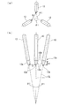
図1は、本実施形態におけるアーク放電装置を示す模式側面図であり、図において、符号1は、アーク放電装置である。
Hereinafter, an embodiment of an arc discharge method and an arc discharge apparatus according to the present invention will be described with reference to the drawings.
FIG. 1 is a schematic side view showing an arc discharge device according to the present embodiment. In the figure,
本実施形態のアーク放電装置1は、24インチ以上の石英ガラスルツボの製造における熱源として利用されるものとして説明するが、非導電体をアーク溶融するための装置であれば、ルツボ口径、装置出力、および、熱源としての用途は限定されるものではなく、この構成に限られるものではない。
The
本実施形態のアーク放電装置1は、図1に示すように、図示しない回転手段によって回転可能とされ石英ガラスルツボの外形を規定するモールド10を有し、モールド10の内部に原料粉(石英粉)が所定厚さに充填されて石英粉成形体11とされる。このモールド10内部には、その内表面に貫通するとともに図示しない減圧手段に接続された通気口12が複数設けられ、石英粉成形体11内部を減圧可能となっている。モールド上側位置には図示しない電力供給手段に接続されたアーク加熱用の炭素電極13,13,13が設けられ、石英粉成形体11を加熱可能とされている。炭素電極13,13,13は、電極位置設定手段20により、図中矢印Tおよび矢印Dで示すように上下動可能および電極間距離Dを設定可能とされている。
As shown in FIG. 1, the
アーク放電装置1は、300kVA〜12,000kVAの出力範囲で、複数の炭素電極13,13,13によりアーク放電によって非導電性対象物(石英粉)を加熱溶融する高出力の装置とされる。
The
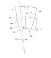
図2は、本実施形態におけるアーク放電装置の炭素電極位置を示す模式側面図である。
炭素電極13,13,13は、例えば、交流3相(R相、S相、T相)のアーク放電をおこなうよう同形状の電極棒とされ、図1,図2に示すように、下方に頂点を有するような逆三角錐状となるように、それぞれの軸線13Lが角度θ1をなすようにそれぞれが設けられている。
FIG. 2 is a schematic side view showing the carbon electrode position of the arc discharge device in the present embodiment.
The
図3は、本実施形態におけるアーク放電装置の炭素電極先端部分を示す拡大模式図である。
炭素電極13は略円柱棒状体とされて、図2,図3に示すように、先端13aには、これら炭素電極13どうしを接触させる接触位置13bを含む接触部分13cが設けられ、該接触部分13cの形状が先端13aに向かって縮径する円錐台部分を有して先端13aの先端面13dと縮径部である側周面13eとを有するものとされる。
FIG. 3 is an enlarged schematic view showing a carbon electrode tip portion of the arc discharge device in the present embodiment.
The
この側周面13eが炭素電極13の軸線13Lとなす角度θ2は、炭素電極13どうしが接触した場合に、その接触位置13bが接触部分13cの範囲内に位置するように設定され、好ましくはθ1>2×θ2とされるが、たとえば、この角度がθ1=2×θ2とされて接触位置13bが円錐台部分と均一径部分との境界付近まで位置している場合でも、接触位置13bが接触部分13cの範囲内に位置することが可能な範囲であればこの限りではない。
The angle θ2 formed by the side
接触部分13cの長さL1は、先端13aから接触位置13bまでの距離L2に対して、L2<L1となるとともに、炭素電極13の径寸法Rに対して、比L1/Rが0〜0.001〜0.9の範囲となるよう設定される。
もちろん、これらは、炭素電極13の軸線13Lどうしの角度θ1および側周面13eが炭素電極13の軸線13Lとなす角度θ2に依存するので、上記の条件を満たすように、これらの範囲が設定されることになる。
The length L1 of the
Of course, since these depend on the angle θ1 between the
なお、本実施形態においては、接触位置13bが先端面13dと側周面13eとの境界となるよう設定されるとともに、先端13aから接触位置13bまでの距離L2がゼロとなるように設定されているが、図2,図3においてはその長さをあえて明示している。
In the present embodiment, the
炭素電極13の接触部分13cは、図2,図3に示すように、他の炭素電極13に接触させた場合に1カ所のみで接触するように凹んだ部分がない形状とされている。いいかえるとて、この接触部分13cおよびそれ以外の部分においては、炭素電極13が2カ所以上で同時に接触しないように、他の1つの電極との再近接距離を有する部分が、一点、または、1つの線状部分、あるいは1つの面状となる1カ所のみとなるように接触部分13cの形状が設定されている。本実施形態においては、θ1=2×θ2として設定した場合に、縮径部の全長にわたって炭素電極13,13どうしが1つの直線状に接触することになる。
As shown in FIGS. 2 and 3, the
炭素電極13は、均一径部分における径寸法Rとアーク放電単位分当たりに消耗する長さ寸法との比が0.02〜0.6の範囲となるよう設定されている。
これは、アーク放電の出力と、石英ガラスルツボの口径(大きさ)によって規定される溶融するべき原料粉の量と、溶融処理の温度等の条件と、必要なアーク放電持続時間と、必要な電極強度とから炭素電極13の径寸法Rが決定されるが、これに加えて、電極振動発生防止の観点から、炭素電極13の径寸法Rへの規定をおこなうものである。
具体的には、32インチの石英ガラスルツボの製造においては、60分で120mm程度、つまり、1分あたり2mm程度であり、この際の炭素電極13の径寸法Rは、20〜30〜100〜120mmとなる。
The
This is because of the arc discharge output, the amount of raw material powder to be melted, which is defined by the diameter (size) of the quartz glass crucible, the conditions such as the temperature of the melting process, the required arc discharge duration, and the necessary The diameter R of the
Specifically, in the production of a 32-inch quartz glass crucible, it is about 120 mm in 60 minutes, that is, about 2 mm per minute, and the diameter R of the
炭素電極13は、粒子径0.3mm以下、好ましくは0.1mm以下、さらに好ましくは粒子径0.05mm以下の高純度炭素粒子によって形成されて、その密度が1.30g/cm3 〜1.80g/cm3 、あるいは1.30g/cm3 〜1.70g/cm3 のとき、電極各相に配置した炭素電極相互の密度差が0.2g/cm3 以下とされることができ、このように高い均質性を有していることによって、発生したアークが安定であり、炭素電極13の局部的な欠落を防止できる。
The
本実施形態のアーク放電装置1は、石英ガラスルツボ製造時におけるアーク放電をおこなう際、各炭素電極13における電力密度が40〜900〜1,700kVA/cm2となるように設定される。具体的には、上述の径寸法Rに設定された炭素電極13に対して、300kVA〜500〜2000〜6000〜10000〜12,000kVAの電力を供給するものとされる。
The
電極位置設定手段20は、図1に示すように、炭素電極13,13,13を、その電極間距離Dを設定可能として支持する支持部21と、この支持部21を水平方向に移動可能とする水平移動手段と、複数の支持部21およびその水平移動手段を一体として上下方向に移動可能とする上下移動手段とを有するものとされ、支持部21においては、炭素電極13が角度設定軸22周りに回動可能に支持され、角度設定軸22の回転角度を制御する回転手段を有している。炭素電極13,13の電極間距離Dを調節するには、図1に矢印で示すように回転手段により炭素電極13の角度を制御するとともに、水平移動手段により支持部21の水平位置を制御する。また、上下移動手段によって支持部21の高さ位置を制御して電極先端部13aの石英粉成形体11底部位置に対する高さ位置を制御することが可能となる。
なお、図には左端の炭素電極13のみに支持部21等を示しているが、他の電極も同様の構成によって支持されており、個々の炭素電極13の高さも個別に制御可能とすることができる。
As shown in FIG. 1, the electrode position setting means 20 supports the
In addition, although the
以下、本実施形態におけるアーク発生方法について説明する。 Hereinafter, an arc generation method in the present embodiment will be described.
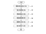
図4は、本実施形態におけるアーク放電方法の時間に対する(a)電極間距離変化(b)電流振幅の一例(c)従来の電流振幅を示すタイムチャートであり、図5は、本実施形態におけるアーク放電方法を示すフローチャートである。
本実施形態のアーク放電方法においては、図5に示すように、電極初期位置設定工程S1、電力供給開始工程S2、電極距離拡大工程S3、電極距離調整工程S4、電極高さ設定工程S5、電力供給終了工程S6を有するものとされる。
FIG. 4 is a time chart showing (a) an interelectrode distance change (b) an example of current amplitude with respect to time of the arc discharge method in the present embodiment (c) a conventional current amplitude, and FIG. 5 is a time chart in the present embodiment. It is a flowchart which shows an arc discharge method.
In the arc discharge method of the present embodiment, as shown in FIG. 5, an electrode initial position setting step S1, a power supply starting step S2, an electrode distance expanding step S3, an electrode distance adjusting step S4, an electrode height setting step S5, and an electric power A supply end step S6 is included.
図5に示す電極初期位置設定工程S1においては、モールド10に石英粉(原料粉)を充填し、石英粉成形体11を所望の状態に成形した後、図1,図2に示すように、炭素電極13,13,13が下方に頂点を有するような逆三角錐状を維持し、かつ、それぞれの軸線13Lが角度θ1を維持しつつ、図3に示すように、先端13aで互いに接触するように電極初期位置を設定する。
In the electrode initial position setting step S1 shown in FIG. 5, after filling the
次いで、図5に示す電力供給開始工程S2においては、図4に示す時刻t0から、図示しない電力供給手段から、上述したように設定される電力量として炭素電極13,13,13に電力供給を開始する。この状態では、アーク放電は発生しない。
Next, in the power supply start step S2 shown in FIG. 5, from the time t0 shown in FIG. 4, power is supplied to the
図5に示す電極距離拡大工程S3においては、図4に示す時刻t1から、電極位置設定手段20により、図2に示すように炭素電極13,13,13が下方に頂点を有するような逆三角錐状を維持し、電極間距離Dを拡大する(削除した理由は、弊社の設備には2種類の開閉機構がある為です。具体的には、貴殿が書かれたようなタイプで、電極角度を位置した状態でスライド移動をして開閉する機構、もう一つは、電極の角度を変更して開閉する機構です。本特許には大きな影響はないと思いますが、いちよう削除させて頂きました。詳しくはP4の図を参照して下さい。)これに伴って、炭素電極13,13間で放電が発生し始める。この際、各炭素電極13における電力密度が40kVA/cm2 〜1,700kVA/cm2となるように電力供給手段により供給電力を制御する。
In the electrode distance expanding step S3 shown in FIG. 5, from the time t1 shown in FIG. 4, the electrode position setting means 20 causes the inverted triangular shape such that the
図5に示す電極距離調整工程S4においては、図4に示す時刻t2から、電極位置設定手段20により、角度θ1を維持した状態で、石英粉成形体11溶融に必要な熱源としての条件を満たすように、電極間距離Dを調節する。この際、各炭素電極13における電力密度が40kVA/cm2 〜1,700kVA/cm2となるように電力供給手段による供給電力制御が維持される。これにより、アーク放電の状態を安定させ、安定したアーク火炎の発生を持続することができる。
また、図4に示す時刻t3から、電極位置設定手段20により電極間距離Dをさらに拡大する制御をおこなうこともできる。
In the electrode distance adjusting step S4 shown in FIG. 5, the condition as a heat source necessary for melting the quartz powder molded
Further, from time t3 shown in FIG. 4, the electrode position setting means 20 can perform control to further increase the inter-electrode distance D.
電極距離調整工程S4と同時に、図5に示す電極高さ設定工程S5として、電極位置設定手段20により、角度θ1を維持した状態で、石英粉成形体11溶融に必要な熱源としての条件を満たすように、電極高さ位置Tを調節する。この際、各炭素電極13における電力密度が40kVA/cm2 〜1,700kVA/cm2となるように電力供給手段による供給電力制御が維持される。
Simultaneously with the electrode distance adjusting step S4, as the electrode height setting step S5 shown in FIG. 5, the electrode position setting means 20 satisfies the condition as a heat source necessary for melting the quartz powder molded
図5に示す電力供給終了工程S6においては、図4に示す時刻t4に、石英粉成形体11溶融が所定の状態になった後に、電力供給手段による電力供給を停止する。このアーク溶融によって、石英粉を溶融して石英ガラスルツボを製造する。
In the power supply end step S6 shown in FIG. 5, the power supply by the power supply means is stopped after the quartz powder molded
なお、上記の各工程において、通気口12に接続した減圧手段によって石英粉成形体11付近の圧力を制御することもできる。
In each of the above steps, the pressure in the vicinity of the quartz powder molded
本実施形態においては、電極初期位置設定工程S1として、炭素電極13,13,13どうしを接触させるとともに、接触位置13bと先端13aとの距離L2の範囲を炭素電極13の径寸法Rに対する比率として上記のように設定することにより、電力供給開始工程S2として通電を開始し、電極距離拡大工程S3および電極距離調整工程S4として炭素電極13距離を設定した場合に、発生する電極振動の振幅が炭素電極13径径寸法Rの0.15倍より大きくなることを防止して、図4(b)に示すように、電極振動による電流変動が起こらないようにすることができる。さらに、電極振動の振幅が炭素電極13径径寸法Rの0.10倍、0.05倍より大きくなることを防止することができる。これにより、もしも電極振動が発生してもそれ以上拡大せずに収束し、電極振動が収まって安定したアークを発生させることが可能となる。
In the present embodiment, as the electrode initial position setting step S1, the
なお、電極振動の振幅が炭素電極13径径寸法Rの0.15倍より大きくしないよう制御した場合には、図4に示す時刻t1から12sec以内に電極振動を収束させることができる。
また、電極振動の振幅が炭素電極13径径寸法Rの0.10倍より大きくしないよう制御した場合には、図4に示す時刻t1から8sec以内に電極振動を収束させることができる。
また、電極震動の振幅が炭素電極13径径寸法Rの0.05倍より大きくしないよう制御した場合には、図4に示す時刻t1から4sec以内に電極振動を収束させることができる。
If the amplitude of the electrode vibration is controlled not to be larger than 0.15 times the diameter R of the
Further, when the control is performed so that the amplitude of the electrode vibration is not larger than 0.10 times the diameter R of the
Further, when the amplitude of the electrode vibration is controlled not to be larger than 0.05 times the diameter R of the
本実施形態においては、電極距離拡大工程S3、電極距離調整工程S4、電極高さ設定工程S5において、各炭素電極13における電力密度が40kVA/cm2 〜1,700kVA/cm2となるように電力供給手段による供給電力制御が維持されることにより、電極振動の増大原因となるローレンツ力を振動増大防止許容範囲内におさめることが可能となるため、炭素電極13で発生した電極振動を収束させることが可能となる。
In the present embodiment, the electrode distance expansion step S3, the electrode distance adjusting step S4, in the electrode height setting step S5, the power to the power density of each
本実施形態において、炭素電極13の接触部分13cは、1カ所のみで他の炭素電極13に接触するように、他の1つの電極との再近接距離を有する部分が1カ所のみとなるようにその形状が設定されていることにより、電極振動が起こりやすい炭素電極13側面での放電発生を防止することができ、接触部分13bの先端からのみ放電をおこなって、安定したアーク火炎の発生と電極振動の防止とを同時に実現することが可能となる。
In the present embodiment, the
本実施形態において、炭素電極13が、均一径部分における径寸法Rとアーク放電単位分当たりに消耗する長さ寸法との比が0.02〜0.6の範囲となるよう設定されていることにより、アーク放電の出力と、石英ガラスルツボの口径(大きさ)によって規定される溶融するべき原料粉の量と、溶融処理の温度等の条件と、必要なアーク放電持続時間と、必要な電極強度と電極震動発生防止の条件を同時に満たして、アーク溶融に必要な熱量を石英粉成形体11溶融に供給できるアーク火炎が発生できるとともに、同時に、電極振動を防止することができるという効果を実現することが可能となる。
In the present embodiment, the
なお、本実施形態においては、接触部分13cが、円錐台形状のものを示したが、次のような構成も可能である。
In the present embodiment, the
図6は、本発明の他の実施形態におけるアーク放電装置の炭素電極先端部分を示す模式図である。
本発明の炭素電極としては、図6(a)に示すように、炭素電極13Aの基部から先端13aに連続的に縮径し、基部の径寸法R1に対し先端13aの径寸法R2が小さく設定されており、その全長に渡る側面13fが円錐台となっているものや、図6(b)に示すように、炭素電極13Bの先端13aにおける接触部分13cが、炭素電極13の軸線13Lに沿った断面輪郭において曲率不連続点が存在しない曲線、例えば楕円弧とされる形状や、図6(c)に示すように、炭素電極13Bの先端13aにおける接触部分13cが、その基部が均一径部に連続する円錐台の側周面13hとされるとともに、この円錐台より先端13a側が、この円錐台となめらかに連続し、かつ、炭素電極13の軸線13Lに沿った断面輪郭において曲率不連続点が存在しない曲線、例えば楕円弧、あるいは円弧とされる形状や、図6(d)に示すように、炭素電極13Dの基部から先端13aに連続的に縮径する円錐状となっているものが可能である。
ここで、図6(a)、図6(d)に示すように接触部分13cにおける基部側の径寸法と電極そのものの基部の径寸法R1が異なるものにおいて、上記の比L1/Rの範囲等を設定する場合には、電極径寸法Rが、図示するように、電極軸線13L方向において接触部分13cにおける基部側位置、つまり電極先端13aから長さL1における直径寸法として設定される。
FIG. 6 is a schematic diagram showing a carbon electrode tip portion of an arc discharge device according to another embodiment of the present invention.
As shown in FIG. 6A, the carbon electrode of the present invention is continuously reduced in diameter from the base of the
Here, as shown in FIGS. 6 (a) and 6 (d), the range of the above ratio L1 / R, etc., in the case where the diameter dimension R1 of the base portion side of the
以下、本発明の実施例について説明する。 Examples of the present invention will be described below.
上述した炭素電極13として以下の寸法のものを用意し、以下のような条件でアーク放電をおこない、石英ガラスルツボを製造した。この際、炭素電極13における電力密度が40kVA/cm2 〜1,700kVA/cm2のものと、それ以外の下記の条件を設定し、これらの結果を比較した。
ルツボ口径;32インチ
出力;3,000kVA
処理時間;30分
電極形状;先端円錐台
θ1;16°
θ2;7°
炭素電極径寸法R;70mm
接触部分長さL1;50mm
接触位置L2;電極先端から10mm
炭素電極における電力密度;30、50、800、1200、1800、2000kVA/cm2
The
Crucible caliber; 32 inch output; 3,000 kVA
Processing time: 30 minutes Electrode shape; Tip frustum θ1; 16 °
θ2: 7 °
Carbon electrode diameter R: 70 mm
Contact part length L1; 50 mm
Contact position L2: 10 mm from the electrode tip
Power density at the carbon electrode; 30, 50, 800, 1200, 1800, 2000 kVA / cm 2
その結果、炭素電極における電力密度;30kVA/cm2 の場合には、アークが定常的に発生しなかったが、電力密度;50kVA/cm2 の場合には、アークが定常的に発生した。
また、炭素電極における電力密度;800,1200kVA/cm2 の場合には、電極振動が炭素電極径寸法Rの0.15倍以内となり、図4(b)に模式的に示すように、発生した振動が収束したが、電力密度;1800、2000kVA/cm2 の場合には、電極振動が炭素電極径寸法Rの0.15倍より大きくなり、図4(c)に模式的に示すように、発生した振動が増大し始めたため、ルツボ製造を停止した。
As a result, when the power density at the carbon electrode; 30 kVA / cm 2 , the arc was not generated constantly, but when the power density was 50 kVA / cm 2 , the arc was generated constantly.
Further, in the case of the power density at the carbon electrode: 800, 1200 kVA / cm 2 , the electrode vibration was within 0.15 times the carbon electrode diameter R, and was generated as schematically shown in FIG. In the case where the vibration is converged but the power density is 1800, 2000 kVA / cm 2 , the electrode vibration is larger than 0.15 times the carbon electrode diameter R, and as schematically shown in FIG. Since the generated vibrations began to increase, crucible production was stopped.
上記の結果から、炭素電極13における電力密度が40kVA/cm2 〜1,700kVA/cm2とすることで、発生した電極振動を収束させることがわかった。
From the above results, the power density of the
次に、電極先端接触位置L2を変化させた実験例について説明する。 Next, an experimental example in which the electrode tip contact position L2 is changed will be described.
電極先端から電極接触点までの距離(L2)を変化させ、以下のような条件でアーク放電をおこない、石英ガラスルツボを製造し、電極振動の振幅と電極破損の有無を検証した。
ルツボ口径;32インチ
出力;3,000kVA
処理時間;30分
電極形状;先端円錐台
θ1;16°
θ2;7°
炭素電極径寸法R;70mm
接触部分長さL1;50mm
炭素電極における電力密度;800kVA/cm2
その結果を表1に示す。
The distance (L2) from the electrode tip to the electrode contact point was changed, arc discharge was performed under the following conditions, a quartz glass crucible was manufactured, and the amplitude of electrode vibration and the presence or absence of electrode breakage were verified.
Crucible caliber; 32 inch output; 3,000 kVA
Treatment time: 30 minutes Electrode shape; Tip frustum θ1; 16 °
θ2: 7 °
Carbon electrode diameter R: 70 mm
Contact part length L1; 50 mm
Power density at the carbon electrode; 800 kVA / cm 2
The results are shown in Table 1.

この結果から、実験例1〜3に示すように、接触位置と先端との距離が前記炭素電極径に対する比率の値が0〜0.9の範囲であれば電極破損が発生せず同時に製造した石英ガラスルツボの状態も好ましいことがわかる。
なお、表1、表2において、不合格とは、アーク放電状態に起因する不具合として、ルツボの肉厚寸法、外径寸法が所望の状態になるまで溶融処理がおこなえなかったこと、あるいは、形状は所定寸法になったとしてもアーク溶融が不十分で、ルツボ内表面付近の無気泡層とする部分において気泡率が充分な割合まで低減しないなど、単結晶引き上げには使用できないルツボ特性となったことを意味するものであり、合格とは、形状、内表面状態などのルツボ特性ともに、所望の基準を満たすようにルツボが製造されたことを意味するものである。
From this result, as shown in Experimental Examples 1 to 3, if the distance between the contact position and the tip is within the range of the ratio of the carbon electrode diameter from 0 to 0.9, no electrode breakage occurred and the electrode was simultaneously manufactured. It can be seen that the state of the quartz glass crucible is also preferable.
In Tables 1 and 2, “fail” means that the melting process could not be performed until the thickness and outer diameter of the crucible reached the desired state, or the shape as a failure caused by the arc discharge state. The crucible characteristics that cannot be used for pulling a single crystal, such as the arc melting is insufficient even when it reaches a predetermined size, and the bubble rate does not decrease to a sufficient rate in the part that forms a bubble-free layer near the inner surface of the crucible. The term “pass” means that the crucible was manufactured so as to satisfy a desired standard in both the shape and the crucible characteristics such as the inner surface state.
次に、電極先端形状を変化させた実験例について説明する。
電極先端形状を図6(a)〜(d)に示す形状として、L2を変化させた実験例と同様の条件として、L2を電極先端から10mmとしてアーク放電させ、その際の電極振幅と電極直径との比を求めた。放電状態とともにその結果を記載する。
放電方向:電極先端面13aから下側方向(電極軸線方向)への放電
電極の振幅/電直直径:0.15より小さい
アーク切れ/電極落下:無
Next, an experimental example in which the electrode tip shape is changed will be described.
The electrode tip shape is the shape shown in FIGS. 6A to 6D, and arc discharge is performed with L2 being 10 mm from the electrode tip under the same conditions as in the experimental example in which L2 is changed. The ratio was calculated. The result is described together with the discharge state.
Discharge direction: Discharge from the electrode
また、先端形状変化の比較例として、電極先端に向けて拡径する電極、円柱電極、円柱部に凹凸のある電極を用い、同様にしてアーク放電させ、その際の電極振幅と電極直径との比を求めた。同様にその結果を記載する。
放電方向:不平等電界による側面放電(側周面13eでの放電)
電極の振幅/電直直径:0.15より大きい
アーク切れ/電極落下:有
In addition, as a comparative example of the tip shape change, an electrode that expands toward the tip of the electrode, a cylindrical electrode, and an electrode that has irregularities on the cylindrical portion are used, and arc discharge is similarly performed. The ratio was determined. Similarly, the result is described.
Discharge direction: Side discharge due to unequal electric field (discharge on side
Electrode amplitude / Direct diameter: Greater than 0.15 Arc break / electrode drop: Existence
これら結果から、図6に示す形状では、安定したアークを良好に発生可能であることがわかる。 From these results, it can be seen that the shape shown in FIG. 6 can satisfactorily generate a stable arc.
次に、電極径寸法とアーク放電単位分当たりに消耗する長さ寸法との比を変化させた実験例について説明する。
電極径寸法とアーク放電単位分当たりに消耗する長さ寸法との比を1.8から87.5まで変化させて、L2を変化させた実験例と同様の条件として、L2を電極先端から10mmとしてアーク放電させ、その際の電極振幅と電極直径との比を求めた。放電状態とともにその結果を記載する。
Next, an experimental example in which the ratio between the electrode diameter dimension and the length dimension consumed per unit arc discharge is changed will be described.
As a condition similar to the experimental example in which L2 was changed by changing the ratio of the electrode diameter dimension and the length dimension consumed per arc discharge unit from 1.8 to 87.5, L2 was 10 mm from the electrode tip. The ratio of the electrode amplitude and the electrode diameter was determined. The result is described together with the discharge state.
この結果から、実験例8〜10に示すように電極径寸法Rとアーク放電単位分当たりに消耗する長さ寸法LLとの比R/LLの値が0.02〜0.6の範囲が好ましいことがわかる。 From this result, as shown in Experimental Examples 8 to 10, the value of the ratio R / LL between the electrode diameter R and the length dimension LL consumed per unit of arc discharge is preferably in the range of 0.02 to 0.6. I understand that.
1…アーク放電装置、13…炭素電極、13b…接触位置、13c…接触部分
DESCRIPTION OF
Claims (7)
アーク放電開始時に前記炭素電極どうしを接触させる接触位置と先端との距離が前記炭素電極径に対する比率として0.001〜0.9の範囲となるよう設定することを特徴とするアーク放電方法。 A method of heating and melting a non-conductive object by arc discharge with a plurality of carbon electrodes in an output range of 300 kVA to 12,000 kVA,
An arc discharge method characterized in that the distance between the contact position where the carbon electrodes are brought into contact with each other at the start of arc discharge and the tip is set in a range of 0.001 to 0.9 as a ratio to the carbon electrode diameter.
前記炭素電極どうしを接触させる接触位置と先端との距離が前記炭素電極径に対する比率として0〜0.9の範囲となるよう前記炭素電極が配置されてなることを特徴とするアーク放電装置。 An apparatus for heating and melting a non-conductive object by arc discharge with a plurality of carbon electrodes in an output range of 300 kVA to 12,000 kVA,
The arc discharge device, wherein the carbon electrodes are arranged such that a distance between a contact position where the carbon electrodes are brought into contact with each other and a tip is in a range of 0 to 0.9 as a ratio to the diameter of the carbon electrode.
原料粉を充填して成形するモールドと、請求項3から5のいずれか記載のアーク放電装置をと、を有してなることを特徴とする石英ガラスルツボ製造装置。 An apparatus for producing a quartz glass crucible by forming a raw material powder in a crucible molding mold and heating and melting the molded body by arc discharge,
A quartz glass crucible manufacturing apparatus comprising: a mold for filling and molding raw material powder; and the arc discharge device according to any one of claims 3 to 5.
Priority Applications (7)
| Application Number | Priority Date | Filing Date | Title |
|---|---|---|---|
| JP2008242874A JP5142912B2 (en) | 2008-09-22 | 2008-09-22 | Arc discharge method, arc discharge device, quartz glass crucible manufacturing device |
| TW098131762A TWI425880B (en) | 2008-09-22 | 2009-09-21 | Method and apparatus for arc discharge and vitreous silica crucible |
| KR1020090088909A KR101094828B1 (en) | 2008-09-22 | 2009-09-21 | Method and apparatus for arc discharge and vitreous silica crucible |
| US12/563,374 US8416833B2 (en) | 2008-09-22 | 2009-09-21 | Arc discharge method, arc discharge apparatus, and fused silica crucible manufacturing apparatus |
| CN2009101732754A CN101686584B (en) | 2008-09-22 | 2009-09-22 | Arc discharge method, arc discharge apparatus, and fused silica crucible manufacturing apparatus and method |
| SG200906262-1A SG160303A1 (en) | 2008-09-22 | 2009-09-22 | Arc discharge method, arc discharge apparatus, and fused silica crucible manufacturing apparatus |
| EP09170981.6A EP2166820B1 (en) | 2008-09-22 | 2009-09-22 | Arc discharge method, arc discharge apparatus, and fused silica crucible manufacturing apparatus |
Applications Claiming Priority (1)
| Application Number | Priority Date | Filing Date | Title |
|---|---|---|---|
| JP2008242874A JP5142912B2 (en) | 2008-09-22 | 2008-09-22 | Arc discharge method, arc discharge device, quartz glass crucible manufacturing device |
Publications (2)
| Publication Number | Publication Date |
|---|---|
| JP2010070440A true JP2010070440A (en) | 2010-04-02 |
| JP5142912B2 JP5142912B2 (en) | 2013-02-13 |
Family
ID=41263907
Family Applications (1)
| Application Number | Title | Priority Date | Filing Date |
|---|---|---|---|
| JP2008242874A Active JP5142912B2 (en) | 2008-09-22 | 2008-09-22 | Arc discharge method, arc discharge device, quartz glass crucible manufacturing device |
Country Status (7)
| Country | Link |
|---|---|
| US (1) | US8416833B2 (en) |
| EP (1) | EP2166820B1 (en) |
| JP (1) | JP5142912B2 (en) |
| KR (1) | KR101094828B1 (en) |
| CN (1) | CN101686584B (en) |
| SG (1) | SG160303A1 (en) |
| TW (1) | TWI425880B (en) |
Cited By (2)
| Publication number | Priority date | Publication date | Assignee | Title |
|---|---|---|---|---|
| US20100170298A1 (en) * | 2009-01-08 | 2010-07-08 | Japan Super Quartz Corporation | Vitreous silica crucible manufacturing apparatus |
| JP2012148961A (en) * | 2010-12-31 | 2012-08-09 | Japan Siper Quarts Corp | Method of manufacturing vitreous silica crucible |
Families Citing this family (9)
| Publication number | Priority date | Publication date | Assignee | Title |
|---|---|---|---|---|
| JP5541777B2 (en) * | 2007-11-30 | 2014-07-09 | 株式会社Sumco | Method and apparatus for producing quartz glass crucible |
| JP5523018B2 (en) * | 2008-08-30 | 2014-06-18 | 株式会社Sumco | Quartz crucible manufacturing equipment |
| JP5344423B2 (en) * | 2008-09-26 | 2013-11-20 | 株式会社Sumco | Method for producing carbon electrode and method for producing quartz glass crucible |
| US8172942B2 (en) * | 2008-10-17 | 2012-05-08 | Japan Super Quartz Corporation | Arc discharge apparatus, apparatus and method for manufacturing vitreous silica glass crucible, and method for pulling up silicon single crystal |
| JP5500687B2 (en) * | 2010-12-02 | 2014-05-21 | 株式会社Sumco | Method and apparatus for producing silica glass crucible |
| KR101293525B1 (en) * | 2011-01-28 | 2013-08-06 | 쟈판 스파 쿼츠 가부시키가이샤 | Apparatus for manufacturing vitreous silica crucible |
| US8281620B1 (en) * | 2011-04-27 | 2012-10-09 | Japan Super Quartz Corporation | Apparatus for manufacturing vitreous silica crucible |
| KR101293870B1 (en) * | 2012-04-27 | 2013-08-07 | 강성인 | Dc arc furnace for melting mineral |
| WO2023143124A1 (en) * | 2022-01-27 | 2023-08-03 | 隆基绿能科技股份有限公司 | Graphite electrode, crucible production device and crucible production method |
Citations (8)
| Publication number | Priority date | Publication date | Assignee | Title |
|---|---|---|---|---|
| JPS62501067A (en) * | 1984-11-05 | 1987-04-30 | 三菱マテリアル株式会社 | Quality improvement method for vitreous silica containers |
| JPH0812359A (en) * | 1994-06-30 | 1996-01-16 | Shinetsu Quartz Prod Co Ltd | Quartz glass crucible and its production |
| JP2000044386A (en) * | 1998-05-25 | 2000-02-15 | Shinetsu Quartz Prod Co Ltd | Silica glass crucible for pulling up silicon single crystal and production of the crucible |
| JP2000264776A (en) * | 1999-03-15 | 2000-09-26 | Toshiba Ceramics Co Ltd | Manufacture of quartz glass crucible for silicon single crystal pulling |
| JP2001501770A (en) * | 1996-08-30 | 2001-02-06 | メルトトラン,インコーポレイテッド | Rotary translation drive mechanism for positioning the device in the melter |
| JP2001097775A (en) * | 1999-09-30 | 2001-04-10 | Toshiba Ceramics Co Ltd | Carbon electrode for melting quartz glass and method for producing the same |
| JP2002068841A (en) * | 2000-08-29 | 2002-03-08 | Mitsubishi Material Quartz Kk | High purity carbon electrode for arc melting |
| JP2004502630A (en) * | 2000-07-11 | 2004-01-29 | ヘレウス・クアルツグラース・ゲゼルシャフト・ミット・ベシュレンクテル・ハフツング・ウント・コンパニー・コマンディット・ゲゼルシャフト | Method for producing rotationally symmetric quartz glass crucible and apparatus for implementing the method |
Family Cites Families (5)
| Publication number | Priority date | Publication date | Assignee | Title |
|---|---|---|---|---|
| JP3647688B2 (en) | 1999-09-21 | 2005-05-18 | 東芝セラミックス株式会社 | Quartz glass crucible manufacturing apparatus and manufacturing method |
| JP4300333B2 (en) * | 2002-03-14 | 2009-07-22 | ジャパンスーパークォーツ株式会社 | Manufacturing method and apparatus for quartz glass crucible by ring arc and quartz glass crucible |
| US20050120945A1 (en) * | 2003-12-03 | 2005-06-09 | General Electric Company | Quartz crucibles having reduced bubble content and method of making thereof |
| US7556764B2 (en) * | 2005-11-09 | 2009-07-07 | Heraeus Shin-Etsu America, Inc. | Silica vessel with nozzle and method of making |
| JP2008242874A (en) | 2007-03-28 | 2008-10-09 | Hitachi Ltd | Control device and authentication control system |
-
2008
- 2008-09-22 JP JP2008242874A patent/JP5142912B2/en active Active
-
2009
- 2009-09-21 KR KR1020090088909A patent/KR101094828B1/en active IP Right Grant
- 2009-09-21 US US12/563,374 patent/US8416833B2/en not_active Expired - Fee Related
- 2009-09-21 TW TW098131762A patent/TWI425880B/en not_active IP Right Cessation
- 2009-09-22 EP EP09170981.6A patent/EP2166820B1/en active Active
- 2009-09-22 CN CN2009101732754A patent/CN101686584B/en active Active
- 2009-09-22 SG SG200906262-1A patent/SG160303A1/en unknown
Patent Citations (8)
| Publication number | Priority date | Publication date | Assignee | Title |
|---|---|---|---|---|
| JPS62501067A (en) * | 1984-11-05 | 1987-04-30 | 三菱マテリアル株式会社 | Quality improvement method for vitreous silica containers |
| JPH0812359A (en) * | 1994-06-30 | 1996-01-16 | Shinetsu Quartz Prod Co Ltd | Quartz glass crucible and its production |
| JP2001501770A (en) * | 1996-08-30 | 2001-02-06 | メルトトラン,インコーポレイテッド | Rotary translation drive mechanism for positioning the device in the melter |
| JP2000044386A (en) * | 1998-05-25 | 2000-02-15 | Shinetsu Quartz Prod Co Ltd | Silica glass crucible for pulling up silicon single crystal and production of the crucible |
| JP2000264776A (en) * | 1999-03-15 | 2000-09-26 | Toshiba Ceramics Co Ltd | Manufacture of quartz glass crucible for silicon single crystal pulling |
| JP2001097775A (en) * | 1999-09-30 | 2001-04-10 | Toshiba Ceramics Co Ltd | Carbon electrode for melting quartz glass and method for producing the same |
| JP2004502630A (en) * | 2000-07-11 | 2004-01-29 | ヘレウス・クアルツグラース・ゲゼルシャフト・ミット・ベシュレンクテル・ハフツング・ウント・コンパニー・コマンディット・ゲゼルシャフト | Method for producing rotationally symmetric quartz glass crucible and apparatus for implementing the method |
| JP2002068841A (en) * | 2000-08-29 | 2002-03-08 | Mitsubishi Material Quartz Kk | High purity carbon electrode for arc melting |
Cited By (4)
| Publication number | Priority date | Publication date | Assignee | Title |
|---|---|---|---|---|
| US20100170298A1 (en) * | 2009-01-08 | 2010-07-08 | Japan Super Quartz Corporation | Vitreous silica crucible manufacturing apparatus |
| JP2010180123A (en) * | 2009-01-08 | 2010-08-19 | Japan Siper Quarts Corp | Vitreous silica crucible manufacturing apparatus |
| US8240169B2 (en) * | 2009-01-08 | 2012-08-14 | Japan Super Quartz Corporation | Vitreous silica crucible manufacturing apparatus |
| JP2012148961A (en) * | 2010-12-31 | 2012-08-09 | Japan Siper Quarts Corp | Method of manufacturing vitreous silica crucible |
Also Published As
| Publication number | Publication date |
|---|---|
| TWI425880B (en) | 2014-02-01 |
| TW201029522A (en) | 2010-08-01 |
| KR20100033941A (en) | 2010-03-31 |
| CN101686584B (en) | 2012-05-30 |
| CN101686584A (en) | 2010-03-31 |
| SG160303A1 (en) | 2010-04-29 |
| EP2166820B1 (en) | 2013-08-21 |
| EP2166820A1 (en) | 2010-03-24 |
| JP5142912B2 (en) | 2013-02-13 |
| US20100071417A1 (en) | 2010-03-25 |
| KR101094828B1 (en) | 2011-12-16 |
| US8416833B2 (en) | 2013-04-09 |
Similar Documents
| Publication | Publication Date | Title |
|---|---|---|
| JP5142912B2 (en) | Arc discharge method, arc discharge device, quartz glass crucible manufacturing device | |
| JP5415297B2 (en) | Quartz glass crucible manufacturing equipment | |
| JP2010076949A (en) | Method and apparatus for producing quartz glass crucible and quartz glass crucible | |
| JP5541777B2 (en) | Method and apparatus for producing quartz glass crucible | |
| JP5388872B2 (en) | Carbon electrode grinding machine | |
| JP5397857B2 (en) | Method and apparatus for producing quartz glass crucible | |
| JP5245129B2 (en) | Method for producing quartz glass crucible | |
| JP2009143770A (en) | High-strength and high-purity quartz glass crucible used for pulling large-diameter silicon single crystal ingot | |
| JP5500687B2 (en) | Method and apparatus for producing silica glass crucible | |
| US9737931B2 (en) | Method for producing platinum group alloy | |
| KR101381326B1 (en) | Method for producing semiconductor wafers composed of silicon | |
| JP2016079065A (en) | Production method and production device of monocrystal | |
| JP2001233629A (en) | Method of producing quartz glass crucible | |
| US8172942B2 (en) | Arc discharge apparatus, apparatus and method for manufacturing vitreous silica glass crucible, and method for pulling up silicon single crystal | |
| EP3828134B1 (en) | Core wire holder, apparatus for preparing silicon, and method for preparing silicon | |
| JP2013112571A (en) | Method and apparatus for manufacturing quartz glass cylinder material | |
| JP3174263U (en) | Silica glass crucible manufacturing equipment | |
| JP7094487B2 (en) | Silica glass crucible manufacturing equipment and silica glass crucible manufacturing method | |
| JP2007210865A (en) | Silicon single crystal pulling device | |
| JP6547574B2 (en) | Selection method of heater related members provided in single crystal pulling apparatus | |
| JP2009113064A (en) | Method for producing ingot | |
| JPH0412089A (en) | Apparatus for producting oxide single crystal | |
| JP2004059400A (en) | Method and apparatus for manufacturing silica glass cylindrical body |
Legal Events
| Date | Code | Title | Description |
|---|---|---|---|
| RD03 | Notification of appointment of power of attorney |
Free format text: JAPANESE INTERMEDIATE CODE: A7423 Effective date: 20110316 |
|
| A621 | Written request for application examination |
Free format text: JAPANESE INTERMEDIATE CODE: A621 Effective date: 20110621 |
|
| A977 | Report on retrieval |
Free format text: JAPANESE INTERMEDIATE CODE: A971007 Effective date: 20120522 |
|
| A131 | Notification of reasons for refusal |
Free format text: JAPANESE INTERMEDIATE CODE: A131 Effective date: 20120530 |
|
| A521 | Request for written amendment filed |
Free format text: JAPANESE INTERMEDIATE CODE: A523 Effective date: 20120726 |
|
| A521 | Request for written amendment filed |
Free format text: JAPANESE INTERMEDIATE CODE: A821 Effective date: 20120727 |
|
| TRDD | Decision of grant or rejection written | ||
| A01 | Written decision to grant a patent or to grant a registration (utility model) |
Free format text: JAPANESE INTERMEDIATE CODE: A01 Effective date: 20121023 |
|
| A01 | Written decision to grant a patent or to grant a registration (utility model) |
Free format text: JAPANESE INTERMEDIATE CODE: A01 |
|
| A61 | First payment of annual fees (during grant procedure) |
Free format text: JAPANESE INTERMEDIATE CODE: A61 Effective date: 20121120 |
|
| FPAY | Renewal fee payment (event date is renewal date of database) |
Free format text: PAYMENT UNTIL: 20151130 Year of fee payment: 3 |
|
| R150 | Certificate of patent or registration of utility model |
Ref document number: 5142912 Country of ref document: JP Free format text: JAPANESE INTERMEDIATE CODE: R150 Free format text: JAPANESE INTERMEDIATE CODE: R150 |
|
| S111 | Request for change of ownership or part of ownership |
Free format text: JAPANESE INTERMEDIATE CODE: R313115 |
|
| FPAY | Renewal fee payment (event date is renewal date of database) |
Free format text: PAYMENT UNTIL: 20151130 Year of fee payment: 3 |
|
| R350 | Written notification of registration of transfer |
Free format text: JAPANESE INTERMEDIATE CODE: R350 |
|
| R250 | Receipt of annual fees |
Free format text: JAPANESE INTERMEDIATE CODE: R250 |
|
| R250 | Receipt of annual fees |
Free format text: JAPANESE INTERMEDIATE CODE: R250 |
|
| R250 | Receipt of annual fees |
Free format text: JAPANESE INTERMEDIATE CODE: R250 |
|
| R250 | Receipt of annual fees |
Free format text: JAPANESE INTERMEDIATE CODE: R250 |
|
| R250 | Receipt of annual fees |
Free format text: JAPANESE INTERMEDIATE CODE: R250 |
|
| R250 | Receipt of annual fees |
Free format text: JAPANESE INTERMEDIATE CODE: R250 |
|
| R250 | Receipt of annual fees |
Free format text: JAPANESE INTERMEDIATE CODE: R250 |
|
| R250 | Receipt of annual fees |
Free format text: JAPANESE INTERMEDIATE CODE: R250 |
|
| R250 | Receipt of annual fees |
Free format text: JAPANESE INTERMEDIATE CODE: R250 |