JP2010069930A - Controller for hybrid vehicle - Google Patents
Controller for hybrid vehicle Download PDFInfo
- Publication number
- JP2010069930A JP2010069930A JP2008236751A JP2008236751A JP2010069930A JP 2010069930 A JP2010069930 A JP 2010069930A JP 2008236751 A JP2008236751 A JP 2008236751A JP 2008236751 A JP2008236751 A JP 2008236751A JP 2010069930 A JP2010069930 A JP 2010069930A
- Authority
- JP
- Japan
- Prior art keywords
- internal combustion
- combustion engine
- starting
- battery
- power
- Prior art date
- Legal status (The legal status is an assumption and is not a legal conclusion. Google has not performed a legal analysis and makes no representation as to the accuracy of the status listed.)
- Granted
Links
- 238000002485 combustion reaction Methods 0.000 claims abstract description 203
- 239000003054 catalyst Substances 0.000 claims abstract description 56
- 230000008929 regeneration Effects 0.000 claims description 15
- 238000011069 regeneration method Methods 0.000 claims description 15
- 230000001172 regenerating effect Effects 0.000 claims description 3
- 230000003197 catalytic effect Effects 0.000 abstract description 54
- 230000006866 deterioration Effects 0.000 abstract description 6
- 230000002401 inhibitory effect Effects 0.000 abstract 2
- 239000000446 fuel Substances 0.000 description 16
- 230000007423 decrease Effects 0.000 description 9
- 238000000034 method Methods 0.000 description 8
- 238000002347 injection Methods 0.000 description 6
- 239000007924 injection Substances 0.000 description 6
- 238000010586 diagram Methods 0.000 description 4
- 230000005611 electricity Effects 0.000 description 4
- 238000010792 warming Methods 0.000 description 2
- UGFAIRIUMAVXCW-UHFFFAOYSA-N Carbon monoxide Chemical compound [O+]#[C-] UGFAIRIUMAVXCW-UHFFFAOYSA-N 0.000 description 1
- 238000001514 detection method Methods 0.000 description 1
- 238000012986 modification Methods 0.000 description 1
- 230000004048 modification Effects 0.000 description 1
- 230000002093 peripheral effect Effects 0.000 description 1
- 239000007787 solid Substances 0.000 description 1
- 230000001360 synchronised effect Effects 0.000 description 1
Images


Classifications
-
- Y—GENERAL TAGGING OF NEW TECHNOLOGICAL DEVELOPMENTS; GENERAL TAGGING OF CROSS-SECTIONAL TECHNOLOGIES SPANNING OVER SEVERAL SECTIONS OF THE IPC; TECHNICAL SUBJECTS COVERED BY FORMER USPC CROSS-REFERENCE ART COLLECTIONS [XRACs] AND DIGESTS
- Y02—TECHNOLOGIES OR APPLICATIONS FOR MITIGATION OR ADAPTATION AGAINST CLIMATE CHANGE
- Y02A—TECHNOLOGIES FOR ADAPTATION TO CLIMATE CHANGE
- Y02A50/00—TECHNOLOGIES FOR ADAPTATION TO CLIMATE CHANGE in human health protection, e.g. against extreme weather
- Y02A50/20—Air quality improvement or preservation, e.g. vehicle emission control or emission reduction by using catalytic converters
-
- Y—GENERAL TAGGING OF NEW TECHNOLOGICAL DEVELOPMENTS; GENERAL TAGGING OF CROSS-SECTIONAL TECHNOLOGIES SPANNING OVER SEVERAL SECTIONS OF THE IPC; TECHNICAL SUBJECTS COVERED BY FORMER USPC CROSS-REFERENCE ART COLLECTIONS [XRACs] AND DIGESTS
- Y02—TECHNOLOGIES OR APPLICATIONS FOR MITIGATION OR ADAPTATION AGAINST CLIMATE CHANGE
- Y02T—CLIMATE CHANGE MITIGATION TECHNOLOGIES RELATED TO TRANSPORTATION
- Y02T10/00—Road transport of goods or passengers
- Y02T10/60—Other road transportation technologies with climate change mitigation effect
- Y02T10/62—Hybrid vehicles
Abstract
Description
本発明は、ハイブリッド車両の制御装置に関する。 The present invention relates to a control device for a hybrid vehicle.
内燃機関の始動時に、触媒床温低下条件が成立しているときには、所定の復帰条件が成立するまでは、所定の出力制限をもって設定された要求駆動力に基づいて内燃機関から出力すべき目標動力を設定する。そして、所定の復帰条件が成立した以降は、所定の出力制限を解除して設定された要求駆動力に基づいて内燃機関から出力すべき目標動力を設定することが開示されている(例えば、特許文献1参照)。
ところで、近年、燃費向上のために、EGRガスが内燃機関に大量に導入される。このようにEGRガスが内燃機関に大量に導入されると、内燃機関から低温の排気が排出される。また、低負荷領域などの運転状態で内燃機関が作動すると、内燃機関から低温且つ低流量の排気が排出される。 Incidentally, in recent years, a large amount of EGR gas has been introduced into an internal combustion engine in order to improve fuel efficiency. When a large amount of EGR gas is introduced into the internal combustion engine in this way, low-temperature exhaust is discharged from the internal combustion engine. Further, when the internal combustion engine is operated in an operating state such as a low load region, low temperature and low flow rate exhaust gas is discharged from the internal combustion engine.
そして、このように低温(且つ低流量)の排気が排出される状態で内燃機関を始動させて触媒の暖機を行うと、触媒は暖機できない。かえって、低温(且つ低流量)の排気が触媒に流入することにより触媒の床温が低下し、触媒が排気を浄化できずに排気を排出してしまい、排気エミッションが悪化する場合がある。 And if the internal combustion engine is started and the catalyst is warmed up in such a state where the low temperature (and low flow rate) exhaust gas is discharged, the catalyst cannot be warmed up. On the contrary, when the low temperature (and low flow rate) exhaust gas flows into the catalyst, the catalyst bed temperature decreases, and the catalyst cannot purify the exhaust gas and exhausts the exhaust gas, which may deteriorate the exhaust emission.
本発明は上記事情に鑑みてなされたものであり、その目的とするところは、ハイブリッド車両の制御装置において、内燃機関の始動時における触媒の床温が低下することを抑制し、排気エミッションが悪化することを抑制する技術を提供することにある。 The present invention has been made in view of the above circumstances, and an object of the present invention is to suppress a decrease in the bed temperature of the catalyst at the start of the internal combustion engine in the hybrid vehicle control device, resulting in a deterioration in exhaust emission. It is in providing the technique which suppresses doing.
本発明にあっては、以下の構成を採用する。すなわち、本発明は、
動力源となる内燃機関と、
バッテリから供給される電気エネルギによって前記内燃機関と共に動力源となり、且つ、回生によって前記バッテリを充電するモータと、
前記内燃機関の排気通路に配置され、排気を浄化する触媒と、
前記触媒の床温を検出する触媒床温検出手段と、
前記モータだけが動力源として作動しているときに、前記触媒床温検出手段が検出する前記触媒の床温が、前記触媒を暖機するために前記内燃機関の作動が必要となる所定温度以下の場合に、前記内燃機関によって必要とされる動力で示される前記内燃機関を始動させる始動閾値を通常時よりも高く設定する設定手段と、
を備えることを特徴とするハイブリッド車両の制御装置である。
In the present invention, the following configuration is adopted. That is, the present invention
An internal combustion engine as a power source;
A motor that serves as a power source together with the internal combustion engine by the electric energy supplied from the battery and charges the battery by regeneration;
A catalyst disposed in an exhaust passage of the internal combustion engine for purifying exhaust;
Catalyst bed temperature detecting means for detecting the bed temperature of the catalyst;
When only the motor is operating as a power source, the catalyst bed temperature detected by the catalyst bed temperature detecting means is equal to or lower than a predetermined temperature at which the operation of the internal combustion engine is required to warm up the catalyst. In this case, setting means for setting a starting threshold value for starting the internal combustion engine indicated by the power required by the internal combustion engine higher than normal time;
A control device for a hybrid vehicle, comprising:
本発明では、モータだけが動力源として作動しているときに、触媒の床温が所定温度以下の場合に、内燃機関を始動させる始動閾値を通常時よりも高く設定する。このため、通常時よりも高く設定された始動閾値よりも低い動力で内燃機関の始動要求があっても内燃機関を始動できない。よって、例えば低温且つ低流量の排気が排出される低負荷領域の運転状態が要求される場合などの低い動力が要求される場合に、内燃機関を始動させてしま
うことがない。つまり、低温(且つ低流量)の排気が排出される状態で内燃機関を始動させて触媒の暖機を行うことがない。したがって、内燃機関の始動時に、低温(且つ低流量)の排気が触媒に流入することはなく、触媒の床温が低下することを抑制でき、触媒が排気を浄化できずに排気を排出してしまうことを抑制でき、排気エミッションが悪化することを抑制できる。
In the present invention, when only the motor operates as a power source and the bed temperature of the catalyst is equal to or lower than a predetermined temperature, the starting threshold value for starting the internal combustion engine is set higher than normal. For this reason, the internal combustion engine cannot be started even when there is a request for starting the internal combustion engine with a power lower than the start threshold set higher than normal. Therefore, the internal combustion engine is not started when low power is required, for example, when an operation state in a low load region where low temperature and low flow rate exhaust gas is discharged is required. That is, the catalyst is not warmed up by starting the internal combustion engine in a state where the low-temperature (and low-flow) exhaust is discharged. Therefore, when the internal combustion engine is started, low temperature (and low flow rate) exhaust gas does not flow into the catalyst, and it is possible to suppress a decrease in the catalyst bed temperature, and the catalyst cannot exhaust the exhaust gas without purifying the exhaust gas. Can be suppressed, and deterioration of exhaust emission can be suppressed.
本発明にあっては、以下の構成を採用する。すなわち、本発明は、
動力源となる内燃機関と、
バッテリから供給される電気エネルギによって前記内燃機関と共に動力源となり、且つ、回生によって前記バッテリを充電するモータと、
前記内燃機関の排気通路に配置され、排気を浄化する触媒と、
前記モータだけが動力源として作動しているときに、前記内燃機関に要求される運転状態が前記内燃機関から排出される排気が低温且つ低流量となる運転状態では前記内燃機関を始動できないように、前記内燃機関によって必要とされる動力で示される前記内燃機関を始動させる始動閾値を通常時よりも高く設定する設定手段と、
を備えることを特徴とするハイブリッド車両の制御装置である。
In the present invention, the following configuration is adopted. That is, the present invention
An internal combustion engine as a power source;
A motor that serves as a power source together with the internal combustion engine by the electric energy supplied from the battery and charges the battery by regeneration;
A catalyst disposed in an exhaust passage of the internal combustion engine for purifying exhaust;
When only the motor is operating as a power source, the operation state required for the internal combustion engine is such that the internal combustion engine cannot be started in an operation state where the exhaust gas discharged from the internal combustion engine has a low temperature and a low flow rate. Setting means for setting a starting threshold value for starting the internal combustion engine indicated by the power required by the internal combustion engine higher than normal;
A control device for a hybrid vehicle, comprising:
本発明では、モータだけが動力源として作動しているときに、内燃機関に要求される運転状態が内燃機関から排出される排気が低温且つ低流量となる運転状態では内燃機関を始動できないように、内燃機関を始動させる始動閾値を通常時よりも高く設定する。このため、内燃機関に要求される運転状態が内燃機関から排出される排気が低温且つ低流量となる運転状態では内燃機関を始動できない。つまり、低温且つ低流量の排気が排出される状態で内燃機関を始動させて触媒の暖機を行うことがない。したがって、内燃機関の始動時に、低温且つ低流量の排気が触媒に流入することはなく、触媒の床温が低下することを抑制でき、触媒が排気を浄化できずに排気を排出してしまうことを抑制でき、排気エミッションが悪化することを抑制できる。 In the present invention, when only the motor is operating as a power source, the operating state required for the internal combustion engine is such that the internal combustion engine cannot be started in an operating state in which the exhaust discharged from the internal combustion engine has a low temperature and a low flow rate. The starting threshold value for starting the internal combustion engine is set to be higher than normal. For this reason, an internal combustion engine cannot be started in the driving | running state in which the exhaust_gas | exhaustion discharged | emitted from an internal combustion engine requires low temperature and low flow volume as the driving | running state requested | required of an internal combustion engine. That is, the catalyst is not warmed up by starting the internal combustion engine in a state where the exhaust gas is discharged at a low temperature and a low flow rate. Therefore, when the internal combustion engine is started, low temperature and low flow rate exhaust gas does not flow into the catalyst, it is possible to prevent the catalyst bed temperature from being lowered, and the catalyst exhausts exhaust gas without purifying the exhaust gas. Can be suppressed, and deterioration of exhaust emission can be suppressed.
前記内燃機関の排気通路から排気の一部をEGRガスとして取り込み、前記内燃機関の吸気通路へ当該EGRガスを還流させるEGR通路と、前記EGR通路に配置され、EGRガス量を制御するEGR弁と、前記設定手段によって前記始動閾値を通常時よりも高く設定して前記内燃機関を始動させる場合に、前記EGR弁の開度を閉じ側に制御するEGR弁制御手段と、を備えるとよい。 An EGR passage that takes in a part of exhaust gas from the exhaust passage of the internal combustion engine as EGR gas and recirculates the EGR gas to the intake passage of the internal combustion engine; an EGR valve that is disposed in the EGR passage and controls the amount of EGR gas; And an EGR valve control means for controlling the opening of the EGR valve to the closed side when the internal combustion engine is started by setting the starting threshold value higher than normal by the setting means.
本発明では、設定手段によって始動閾値を通常時よりも高く設定して内燃機関を始動させる場合に、EGR弁の開度を閉じ側に制御する。このため、内燃機関が低温の排気を排出することになるEGRガスの供給が削減されて、内燃機関の始動時に内燃機関から排出される排気が高温となる。よって、高温の排気が排出される状態で内燃機関を始動させて触媒の暖機を行うことができる。したがって、触媒の床温を早期に上昇させることができる。 In the present invention, the opening degree of the EGR valve is controlled to the closed side when the internal combustion engine is started by setting the starting threshold value higher than normal by the setting means. For this reason, the supply of EGR gas from which the internal combustion engine discharges low-temperature exhaust gas is reduced, and the exhaust gas discharged from the internal combustion engine when the internal combustion engine is started becomes high temperature. Therefore, it is possible to warm up the catalyst by starting the internal combustion engine in a state where high-temperature exhaust gas is discharged. Therefore, the bed temperature of the catalyst can be raised early.
前記設定手段によって前記始動閾値を通常時よりも高く設定した後に前記内燃機関が始動した場合に、始動後の前記内燃機関の動力の一部を用いた前記モータの回生によって前記バッテリを充電し、始動後の前記内燃機関の動力を大きくする制御手段を備えるとよい。 When the internal combustion engine is started after the start threshold is set higher than normal by the setting means, the battery is charged by regeneration of the motor using a part of the power of the internal combustion engine after the start, Control means for increasing the power of the internal combustion engine after startup may be provided.
本発明では、始動後の内燃機関の動力を大きくするので、始動後の内燃機関に要求される運転状態が内燃機関から排出される排気が高温且つ高流量となる運転状態となる。よって、高温且つ高流量の排気が排出される状態で内燃機関を作動させて触媒の暖機を行うことができる。したがって、触媒の床温を早期に上昇させることができる。また、モータの回生によってバッテリを充電できる。 In the present invention, since the power of the internal combustion engine after starting is increased, the operating state required for the internal combustion engine after starting becomes an operating state in which the exhaust gas discharged from the internal combustion engine has a high temperature and a high flow rate. Therefore, it is possible to warm up the catalyst by operating the internal combustion engine in a state where exhaust gas having a high temperature and a high flow rate is discharged. Therefore, the bed temperature of the catalyst can be raised early. Further, the battery can be charged by regeneration of the motor.
前記制御手段は、始動後の前記内燃機関の動力の一部を用いた前記モータの回生によって前記バッテリを充電する際の前記バッテリを充電する要求充電量を通常時よりも高くし、始動後の前記内燃機関の動力を大きくするとよい。 The control means increases a required charge amount for charging the battery by regenerating the motor using a part of the power of the internal combustion engine after starting higher than normal, and charges the battery after starting. The power of the internal combustion engine may be increased.
本発明では、始動後の内燃機関の動力をさらに大きくするので、始動後の内燃機関に要求される運転状態が内燃機関から排出される排気がさらに高温且つ高流量となる運転状態となる。よって、さらに高温且つ高流量の排気が排出される状態で内燃機関を作動させて触媒の暖機を行うことができる。したがって、触媒の床温をさらに早期に上昇させることができる。また、バッテリを充電する要求充電量を通常時よりも高くするので、早期にバッテリを充電できる。 In the present invention, since the power of the internal combustion engine after starting is further increased, the operating state required for the internal combustion engine after starting becomes an operating state in which the exhaust discharged from the internal combustion engine has a higher temperature and a higher flow rate. Therefore, it is possible to warm up the catalyst by operating the internal combustion engine in a state where exhaust gas at a higher temperature and higher flow rate is discharged. Accordingly, the bed temperature of the catalyst can be raised even earlier. Further, since the required charge amount for charging the battery is made higher than normal, the battery can be charged early.
本発明によると、ハイブリッド車両の制御装置において、内燃機関の始動時における触媒の床温が低下することを抑制でき、排気エミッションが悪化することを抑制できる。 According to the present invention, in the control apparatus for a hybrid vehicle, it is possible to suppress a decrease in the bed temperature of the catalyst at the time of starting the internal combustion engine, and it is possible to suppress a deterioration in exhaust emission.
以下に本発明の具体的な実施例を説明する。 Specific examples of the present invention will be described below.
<実施例1>
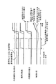
図1は、本実施例に係るハイブリッド車両の制御装置を適用するハイブリッド車両100の概略構成を示す図である。図1に示すハイブリッド車両100は、車軸110、車輪120、ECU200、内燃機関300、モータジェネレータ400、モータ500、動力分割機構600、インバータ700、及びバッテリ800を備えている。
<Example 1>
FIG. 1 is a diagram illustrating a schematic configuration of a
車軸110は、内燃機関300、モータジェネレータ400及びモータ500から出力された動力を車輪120に伝達するための軸である。車輪120は、車軸110を介して伝達される動力を路面に伝達する手段であり、図1においては左右一輪ずつ示されているが、実際には前後左右に一輪ずつ配置されハイブリッド車両全体で4つ備えられる。
The
ECU200は、ハイブリッド車両100の動作全体を制御する電子制御ユニットである。ECU200は、ROMに格納された制御プログラムに従って各種制御を実行する。
The
内燃機関300は、図2に示す気筒301を4つ有するガソリン内燃機関である。内燃機関300は、ハイブリッド車両100の動力源となる。なお、内燃機関300の詳細な構成については後述する。
The
モータジェネレータ400は、内燃機関300と同様にハイブリッド車両100の動力源となる電動機として機能する。またモータジェネレータ400は、バッテリ800を充電するための発電機としても機能する。本実施例のモータジェネレータ400が本発明のモータに相当する。
Similar to the
モータ500は、内燃機関300の駆動力をアシスト(補助)する電動機として機能する。本実施例のモータ500も本発明のモータの一部に相当する。
The
なお、モータジェネレータ400及びモータ500は、例えば同期電動発電機として構成され、外周面に複数個の永久磁石を有するロータと、回転磁界を形成する三相コイルが巻回されたステータとを備える。またこれらは、他の形式のものであってもよい。
動力分割機構600は、内燃機関300の動力をモータジェネレータ400及び車軸1
10へ分配することができる遊星歯車機構である。
The
10 is a planetary gear mechanism that can be distributed to ten.
インバータ700は、バッテリ800から取り出した直流電気を交流電気に変換してモータジェネレータ400及びモータ500に供給すると共に、モータジェネレータ400によって発電された交流電気を直流電気に変換してバッテリ800に供給する。
バッテリ800は、モータジェネレータ400及びモータ500を動作可能にする電気エネルギを供給する電気エネルギ供給源であり、供給する電気エネルギを充電可能な蓄電池である。
The
次に内燃機関300について説明する。図2は内燃機関300の概略構成を示す図である。内燃機関300は、図2に示す気筒301を4つ有する水冷式の4ストロークサイクル・ガソリン内燃機関である。
Next, the
内燃機関300の気筒301内には、ピストン302が摺動自在に設けられている。気筒301内上部の燃焼室303には、吸気ポート304及び排気ポート305が接続されている。
A
吸気ポート304には、気筒301内の燃焼室303に燃料を供給する燃料噴射弁306が設けられている。燃料噴射弁306は、燃料噴射方向が燃焼室303へ向かっている。燃料噴射弁306はECU200に電気的に接続されており、ECU200によって制御される。
The
吸気ポート304の燃焼室303への開口部は吸気弁307によって開閉され、排気ポート305の燃焼室303への開口部は排気弁308によって開閉される。吸気ポート304は吸気通路309に接続され、排気ポート305は排気通路310に接続されている。
The opening of the
排気通路310及び吸気通路309は、EGR通路311によって接続されている。EGR通路311は、排気通路310から排気の一部をEGRガスとして取り込み、吸気通路309へ当該EGRガスを還流させる。このEGR通路311には、当該EGR通路311を流通するEGRガス量を制御するEGR弁312が配置されている。EGR弁312はECU200に電気的に接続されており、ECU200によってEGR弁312の開度が制御される。
The
EGR通路311との接続部位よりも下流側の排気通路310には、触媒コンバータ313が配置されている。触媒コンバータ313は、例えば三元触媒等を有し、内燃機関300から排出される排気を浄化する。本実施例の触媒コンバータ313が本発明の触媒に相当する。
A
触媒コンバータ313の直下流側の排気通路310には、触媒床温センサ314が配置されている。触媒床温センサ314は触媒コンバータ313の床温を検出する。触媒床温センサ314はECU200に電気的に接続されており、触媒床温センサ314の出力値がECU200に入力される。本実施例の触媒床温センサが本発明の触媒床温検出手段に相当する。
A catalyst
内燃機関300には、クランクポジションセンサ315が設けられている。クランクポジションセンサ315は内燃機関300のクランクシャフトのクランク角を検出する。クランクポジションセンサ315はECU200に電気的に接続されており、クランクポジションセンサ315の出力値がECU200に入力される。そしてECU200はクラン
クポジションセンサ315の出力値に基づいて内燃機関300の機関回転数を算出する。
The
そしてECU200は、触媒床温センサ314、クランクポジションセンサ315、アクセルポジションセンサ130、車速センサ140、バッテリ800の充電量を検出するSOCセンサ150等の出力信号を受けて内燃機関300の運転状態を含むハイブリッド車両100の状態を判別し、判別された状態に基づいてハイブリッド車両100を電気的に制御する。
図1のハイブリッド車両100においては、内燃機関300、主として発電機として機能するモータジェネレータ400、及び電動機として機能するモータ500の夫々の動力分配がECU200及び動力分割機構600により制御され、走行状態が制御される。以下に幾つかの状況に応じたハイブリッド車両100の動作について説明する。
In
ハイブリッド車両100の始動時においては、バッテリ800の電気エネルギを用いて駆動されるモータ500が電動機として機能し、モータ500の動力によって内燃機関300がクランキングされ内燃機関300が始動する。
When the
ハイブリッド車両100の発進時には、SOCセンサ150の出力信号に基づいたバッテリ800の充電量に応じて2種類の態様を選択する。例えば、バッテリ800が十分蓄電されている発進時においては、モータジェネレータ400によってバッテリ800を充電する必要が無いため、内燃機関300は暖機のためだけに始動し、ハイブリッド車両100はモータ500の動力によって発進する。一方、バッテリ800があまり蓄電されていない発進時においては、内燃機関300の動力を用いたモータジェネレータ400の回生によってモータジェネレータ400が発電機として機能し、バッテリ800が充電されつつ、ハイブリッド車両100は内燃機関300の動力によって発進する。
When the
ハイブリッド車両100が低速走行時や緩やかな坂を下っている軽負荷走行時には、内燃機関300を運転すると燃焼効率等の効率が悪くなるため、燃料噴射弁306からの燃料噴射が停止されて内燃機関300が停止され、ハイブリッド車両100はモータ500による動力のみで走行する(以下、EV走行という)。この際、バッテリ800があまり充電されていない場合には、内燃機関300がモータジェネレータ400を回生作動させるためだけに駆動され、内燃機関300の動力を用いたモータジェネレータ400の回生によってバッテリ800の充電を行ってもよい。
When the
ハイブリッド車両100の通常走行時のように内燃機関300の燃焼効率等の効率が良好な運転領域においては、ハイブリッド車両100は主として内燃機関300の動力によって走行する。この際、内燃機関300の動力は、動力分割機構600によって2系統に分割され、一方は車軸110を介して車輪120に伝達され、他方はモータジェネレータ400を回生作動させ発電を行わせる。このとき発電された電気エネルギによってモータ500を駆動させ、モータ500によって内燃機関300の動力がアシストされる。この際バッテリ800があまり充電されていない場合には、内燃機関300の動力を上昇させて、内燃機関300のその上昇させた動力を用いたモータジェネレータ400の回生によって発電される電気エネルギを多くし、その電気エネルギの一部でバッテリ800の充電を行ってもよい。
In an operating region where the efficiency such as the combustion efficiency of the
ハイブリッド車両100の減速時には、車輪120から車軸110を介して伝達される動力を用いたモータジェネレータ400の回生によってモータジェネレータ400を発電機として作動させる。これにより車輪120の運動エネルギが電気エネルギに変換され、ハイブリッド車両100が減速されると共にバッテリ800が充電される(回生ブレーキ)。
When the
以上のように動作が変更されるハイブリッド車両100においては、内燃機関300が機関停止され、ハイブリッド車両100がモータ500による動力のみで走行するEV走行を行う場合がある。ハイブリッド車両100のEV走行中には、内燃機関300が機関停止されているため、触媒コンバータ313に排気が流入せず、触媒コンバータ313の床温の維持が困難である。このため、内燃機関300が始動されるときには、触媒コンバータ313の暖機を行うことが望まれる。
In
ここで、近年、燃費向上のために、EGRガスが内燃機関300に大量に導入される。このようにEGRガスが内燃機関300に大量に導入されると、内燃機関300から低温の排気が排出される。また、低負荷領域などの運転状態で内燃機関300が作動すると、内燃機関300から低温且つ低流量の排気が排出される。
Here, in recent years, a large amount of EGR gas is introduced into the
そして、このように低温(且つ低流量)の排気が排出される状態で内燃機関300を始動させて触媒コンバータ313の暖機を行うと、触媒コンバータ313は暖機できない。かえって、低温(且つ低流量)の排気が触媒コンバータ313に流入することにより触媒コンバータ313の床温が低下して触媒不活性状態となり、触媒コンバータ313が排気を浄化できずに排気を排出してしまい、排気エミッションが悪化する場合がある。このように、内燃機関300を始動させても、触媒コンバータ313の暖機ができない場合があった。
Then, when the
そこで、本実施例では、モータ500(又はモータジェネレータ400)だけが動力源として作動しているEV走行のときに、触媒床温センサ314が検出する触媒コンバータ313の床温が、触媒コンバータ313を暖機するために内燃機関300の作動が必要となる所定温度以下の場合に、内燃機関300によって必要とされる動力で示される内燃機関300を始動させる始動閾値(機関起動スレッシュ)を通常時よりも高く設定するようにした。
Therefore, in the present embodiment, the bed temperature of the
ここで、触媒コンバータ313の床温が所定温度とは、それ以下の温度であると、触媒コンバータ313を暖機するために内燃機関300の作動が必要となる閾値の温度である。
Here, if the bed temperature of the
本実施例によると、EV走行しているときに、触媒コンバータ313の床温が所定温度以下の場合に、内燃機関300を始動させる始動閾値を通常時よりも高く設定する。このため、通常時よりも高く設定された始動閾値よりも低い動力で内燃機関300の始動要求があっても内燃機関300を始動できない。よって、例えば低温且つ低流量の排気が排出される低負荷領域の運転状態が要求される場合などの低い動力で内燃機関300を始動させてしまうことがない。つまり、低温(且つ低流量)の排気が排出される状態で内燃機関300を始動させて触媒コンバータ313の暖機を行うことがない。したがって、内燃機関300の始動時に、低温(且つ低流量)の排気が触媒コンバータ313に流入することはなく、触媒コンバータ313の床温が低下することを抑制でき、触媒コンバータ313が排気を浄化できずに排気を排出してしまうことを抑制でき、排気エミッションが悪化することを抑制できる。
According to this embodiment, when the vehicle is running on EV and the bed temperature of the
例えば、EV走行しているときに、触媒コンバータ313の床温が所定温度以下の場合に、内燃機関300を始動させる始動閾値を通常時のままに設定すると、図3の破線に示すようになる。すなわち、通常時の始動閾値を超える、一時的な低温且つ低流量の排気が排出される低負荷領域の運転状態が要求される場合であっても、内燃機関300が始動されてしまう。そうすると、低温且つ低流量の排気が排出される状態でも内燃機関300を始動させて触媒コンバータ313の暖機を行なってしまう。したがって、内燃機関300
が始動されて低温且つ低流量の排気が触媒コンバータ313に流入することにより、触媒コンバータ313の床温が低下してしまう。そして、触媒不活性状態となった触媒コンバータ313が排気を浄化できずに排気を排出してしまい、排気エミッションが悪化する。また、このように先の低温且つ低流量の排気が排出される状態での内燃機関300の作動によって、触媒コンバータ313の床温が低下してしまう。よって、その後、内燃機関300が再度機関停止され、次に高温且つ高流量の排気が排出される状態で内燃機関300を始動させても、触媒コンバータ313の床温が低下した状態から触媒コンバータ313を暖機することになる。このため、触媒コンバータ313の暖機に時間がかかることになる。
For example, if the starting threshold value for starting the
Is started and the low temperature and low flow rate exhaust gas flows into the
これに対し、本実施例のように、EV走行しているときに、触媒コンバータ313の床温が所定温度以下の場合に、内燃機関300を始動させる始動閾値を通常時よりも高く設定すると、図3の実線に示すようになる。すなわち、通常時の始動閾値を超える、一時的な低温且つ低流量の排気が排出される低負荷領域の運転状態が要求される場合には、高く設定した始動閾値を超えないので、内燃機関300が始動されず、EV走行が継続される。そうすると、低温且つ低流量の排気が排出される状態で内燃機関300を始動させないので、低温且つ低流量の排気が触媒コンバータ313に流入せず、触媒コンバータ313の床温が低下してしまうことを抑制できる。つまり、触媒コンバータ313の床温をそのまま維持しておくことができる。また、その後、高く設定された始動閾値を超える、高温且つ高流量の排気が排出される運転状態が要求される場合には、内燃機関300が始動され、触媒コンバータ313の床温が維持された状態から触媒コンバータ313の暖機を行うので、触媒コンバータ313の暖機が早期に行える。
On the other hand, when the floor temperature of the
また、本実施例では、始動閾値を通常時よりも高く設定して内燃機関300を始動させる場合に、EGR弁312の開度を全閉に制御するようにした。なお、この場合のEGR弁312の開度の制御は、全閉だけでなく閉じ側に制御するものであってもよい。
In this embodiment, when the
本実施例によると、始動閾値を通常時よりも高く設定して内燃機関300を始動させる場合に、EGR弁312の開度を全閉に制御する。このため、低温の排気を排出することになるEGRガスの供給が無くなり、内燃機関300の始動時に内燃機関300から排出される排気が高温となる。よって、高温の排気が排出される状態で内燃機関300を始動させて触媒コンバータ313の暖機を行うことができる。したがって、触媒コンバータ313の床温を早期に上昇させることができる。
According to the present embodiment, when the
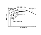
なお、上記のようにEGR弁312の開度を全閉に制御する場合には、EGRガスの供給が無くなったことにより、燃費が低下するので、その燃費の低下分を内燃機関300の動作線を図4の矢印に示すように破線から実線に変更して、燃費を維持するようにする。すなわち、通常時では、NV(ノイズ・バイブレーション)対策により燃費最適ラインからずらしているNVラインに動作線が破線で示すように設定されている。この動作線を、EGRガスの供給が無いことによる燃焼向上により、実線のように燃費最適ラインに近づける。このように動作線を燃費最適ラインに近づけることにより、燃費を向上し、EGRガスの供給が無くなったことによる燃費の低下分を相殺する。
Note that, when the opening degree of the
また、本実施例では、始動閾値を通常時よりも高く設定した後に内燃機関300が始動した場合に、始動後の内燃機関300の動力の一部を用いたモータジェネレータ400の回生によってバッテリ800を充電し、始動後の内燃機関300の動力を大きくするようにした。
Further, in this embodiment, when the
本実施例によると、始動後の内燃機関300の動力を大きくするので、始動後の内燃機関300に要求される運転状態が内燃機関300から排出される排気がより高温且つ高流
量となる運転状態となる。よって、より高温且つ高流量の排気が排出される状態で内燃機関300を作動させて触媒コンバータ313の暖機を継続して行うことができる。したがって、触媒コンバータ313の床温を早期に上昇させることができる。また、同時に、モータジェネレータ400の回生によってバッテリ800を充電し、始動閾値を通常時よりも高く設定したことによりEV走行量が多くなって消耗したバッテリ800の電気エネルギを回復できる。
According to the present embodiment, since the power of the
さらに、本実施例では、始動後の内燃機関300の動力の一部を用いたモータジェネレータ400の回生によってバッテリ800を充電する際のバッテリ800を充電する要求充電量を通常時よりも高くし、始動後の内燃機関300の動力をさらに大きくするようにした。
Furthermore, in the present embodiment, the required charge amount for charging the
本実施例によると、始動後の内燃機関300の動力をさらに一層大きくするので、始動後の内燃機関300に要求される運転状態が内燃機関300から排出される排気がさらに一層高温且つ高流量となる運転状態となる。よって、さらに一層高温且つ高流量の排気が排出される状態で内燃機関300を作動させて触媒コンバータ313の暖機を行うことができる。したがって、触媒コンバータ313の床温をさらに早期に上昇させることができる。また、バッテリ800を充電する要求充電量を通常時よりも高くするので、早期にバッテリ800を充電できる。
According to the present embodiment, since the power of the
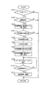
次に、本実施例による内燃機関300の始動時の制御ルーチンについて説明する。図5は、本実施例による内燃機関300の始動時の制御ルーチンを示したフローチャートである。本ルーチンは、所定の時間毎に繰り返し実行される。
Next, a control routine when starting the
ステップS101では、ハイブリッド車両100がEV走行しているか否かを判別する。
In step S101, it is determined whether or not the
ステップS101においてEV走行していると肯定判定された場合には、ステップS102へ移行する。ステップS101においてEV走行していないと否定判定された場合には、本ルーチンを一旦終了する。 If an affirmative determination is made in step S101 that the vehicle is running EV, the process proceeds to step S102. If a negative determination is made in step S101 that the vehicle is not traveling EV, this routine is temporarily terminated.
ステップS102では、触媒コンバータ313の床温が所定温度以下か否か判別する。触媒コンバータ313の床温は、触媒床温センサ314によって検出する。ここで所定温度は予め定まっている。
In step S102, it is determined whether or not the bed temperature of the
ステップS102において触媒コンバータ313の床温が所定温度以下であると肯定判定された場合には、ステップS103へ移行する。ステップS102において触媒コンバータ313の床温が所定温度以下ではないと否定判定された場合には、本ルーチンを一旦終了する。
If it is determined in step S102 that the bed temperature of the
ステップS103では、始動閾値(機関起動スレッシュ)を通常時よりも高く設定する。高く設定する始動閾値は予め定まっている。なお、ステップS101−S103の処理を実行するECU200が本発明の設定手段に相当する。 In step S103, the start threshold (engine start threshold) is set higher than normal. The starting threshold value to be set high is determined in advance. In addition, ECU200 which performs the process of step S101-S103 corresponds to the setting means of this invention.
ステップS104では、内燃機関300が始動可能か否かを判別する。内燃機関300の始動要求動力がステップS103で設定した通常時よりも高い始動閾値を超える場合に内燃機関300を始動可能と判断する。
In step S104, it is determined whether or not the
ステップS104において内燃機関300が始動可能であると肯定判定された場合には、ステップS105へ移行する。ステップS104において内燃機関300が始動可能で
はないと否定判定された場合には、本ルーチンを一旦終了する。
When it is determined in step S104 that the
ステップS105では、内燃機関300を始動する。
In step S105, the
ステップS106では、EGR弁312の開度を全閉に制御する。本ステップの処理を実行するECU200が本発明のEGR弁制御手段に相当する。
In step S106, the opening degree of the
ステップS107では、内燃機関300の動作線を燃費最適ラインに近づけるように図4に示す破線から実線に変更する。
In step S107, the operating line of the
ステップS108では、バッテリ800を充電する要求充電量を通常時よりも高く設定する。
In step S108, the required charge amount for charging
ステップS109では、内燃機関300の動力の一部を用いたモータジェネレータ400の回生を行う。この際、バッテリ800を充電する要求充電量はステップS108で通常時よりも高く設定されている。これにより、内燃機関300の目標動力が大きくなり、始動後の内燃機関300の動力を大きくできる。なお、ステップS108−S109の処理を実行するECU200が本発明の制御手段に相当する。
In step S109, the
ステップS110では、触媒コンバータ313の暖機が終了したか否かを判別する。触媒床温センサ314の出力値が暖機終了値を超える場合に、触媒コンバータ313の暖機が終了したと判断する。暖機終了値は、予め定まっている。
In step S110, it is determined whether or not the warm-up of the
ステップS110において暖機が終了したと肯定判定された場合には、ステップS111へ移行する。ステップS110において暖機が終了していないと否定判定された場合には、ステップS109へ戻る。 If it is determined affirmative in step S110 that the warm-up has been completed, the process proceeds to step S111. If it is determined in step S110 that the warm-up has not ended, the process returns to step S109.
ステップS111では、本ルーチンでの各種設定を解除し、通常制御へ復帰させる。すなわち、始動閾値を通常時のものへ復帰させる。EGR弁312を全閉状態から通常制御へ復帰させる。内燃機関300の変更された実線の動作線を通常時の破線の動作線へ復帰させる。要求充電量を通常時のものへ復帰させる。内燃機関300の動力の一部を用いたモータジェネレータ400の回生を終了し、ハイブリッド車両100の通常制御へ復帰させる。本ステップの処理の後、本ルーチンを一旦終了する。
In step S111, various settings in this routine are canceled and the normal control is resumed. That is, the starting threshold value is returned to the normal one. The
以上説明した本ルーチンによれば、EV走行しているときに、触媒コンバータ313の床温が、所定温度以下の場合に、始動閾値を通常時よりも高く設定できる。これにより、通常時よりも高く設定された始動閾値よりも低い動力で内燃機関300の始動要求があっても内燃機関300を始動できなくする。
According to this routine described above, the start threshold value can be set higher than normal when the bed temperature of the
なお、本ルーチンでは、ステップS102において触媒コンバータ313の床温が所定温度以下であると判定した場合に、ステップS103で始動閾値を通常時よりも高く設定するようにした。しかし、本発明はこれに限られない。例えば、ステップS102の処理を無くしてしまい、ステップS101においてEV走行していると判定した場合に、ステップS103で始動閾値を通常時よりも高く設定するようにしてもよい。これによると、EV走行しているときに、内燃機関300に要求される運転状態が内燃機関300から排出される排気が低温且つ低流量となる運転状態では内燃機関300を始動できないように、内燃機関300によって必要とされる動力で示される内燃機関300を始動させる始動閾値を通常時よりも高く設定することができる。
In this routine, when it is determined in step S102 that the bed temperature of the
なお、本実施例では、本発明のモータとして、モータジェネレータ400を挙げた。さ
らに、内燃機関300を機関停止したEV走行する場合には、モータ500が駆動源となるとした。しかしながら本発明のモータはこれに限られず、モータとして、1つのモータジェネレータでもよく、又は電動機と発電機とをそれぞれ別に備えるものでもよい。
In this embodiment, the
本発明に係るハイブリッド車両の制御装置は、上述の実施例に限定されるものではなく、本発明の要旨を逸脱しない範囲内において種々の変更を加えてもよい。 The hybrid vehicle control device according to the present invention is not limited to the above-described embodiments, and various modifications may be made without departing from the scope of the present invention.
100 ハイブリッド車両
200 ECU
300 内燃機関
309 吸気通路
310 排気通路
311 EGR通路
312 EGR弁
313 触媒コンバータ
314 触媒床温センサ
400 モータジェネレータ
500 モータ
800 バッテリ
100
300
Claims (5)
バッテリから供給される電気エネルギによって前記内燃機関と共に動力源となり、且つ、回生によって前記バッテリを充電するモータと、
前記内燃機関の排気通路に配置され、排気を浄化する触媒と、
前記触媒の床温を検出する触媒床温検出手段と、
前記モータだけが動力源として作動しているときに、前記触媒床温検出手段が検出する前記触媒の床温が、前記触媒を暖機するために前記内燃機関の作動が必要となる所定温度以下の場合に、前記内燃機関によって必要とされる動力で示される前記内燃機関を始動させる始動閾値を通常時よりも高く設定する設定手段と、
を備えることを特徴とするハイブリッド車両の制御装置。 An internal combustion engine as a power source;
A motor that serves as a power source together with the internal combustion engine by the electric energy supplied from the battery and charges the battery by regeneration;
A catalyst disposed in an exhaust passage of the internal combustion engine for purifying exhaust;
Catalyst bed temperature detecting means for detecting the bed temperature of the catalyst;
When only the motor is operating as a power source, the catalyst bed temperature detected by the catalyst bed temperature detecting means is equal to or lower than a predetermined temperature at which the operation of the internal combustion engine is required to warm up the catalyst. In this case, setting means for setting a starting threshold value for starting the internal combustion engine indicated by the power required by the internal combustion engine higher than normal time;
A control apparatus for a hybrid vehicle, comprising:
バッテリから供給される電気エネルギによって前記内燃機関と共に動力源となり、且つ、回生によって前記バッテリを充電するモータと、
前記内燃機関の排気通路に配置され、排気を浄化する触媒と、
前記モータだけが動力源として作動しているときに、前記内燃機関に要求される運転状態が前記内燃機関から排出される排気が低温且つ低流量となる運転状態では前記内燃機関を始動できないように、前記内燃機関によって必要とされる動力で示される前記内燃機関を始動させる始動閾値を通常時よりも高く設定する設定手段と、
を備えることを特徴とするハイブリッド車両の制御装置。 An internal combustion engine as a power source;
A motor that serves as a power source together with the internal combustion engine by the electric energy supplied from the battery and charges the battery by regeneration;
A catalyst disposed in an exhaust passage of the internal combustion engine for purifying exhaust;
When only the motor is operating as a power source, the operating state required for the internal combustion engine is such that the internal combustion engine cannot be started in an operating state where the exhaust gas discharged from the internal combustion engine has a low temperature and a low flow rate. Setting means for setting a starting threshold value for starting the internal combustion engine indicated by the power required by the internal combustion engine higher than normal;
A control apparatus for a hybrid vehicle, comprising:
前記EGR通路に配置され、EGRガス量を制御するEGR弁と、
前記設定手段によって前記始動閾値を通常時よりも高く設定して前記内燃機関を始動させる場合に、前記EGR弁の開度を閉じ側に制御するEGR弁制御手段と、
を備えることを特徴とする請求項1又は2に記載のハイブリッド車両の制御装置。 An EGR passage that takes in part of exhaust gas from the exhaust passage of the internal combustion engine as EGR gas and recirculates the EGR gas to the intake passage of the internal combustion engine;
An EGR valve disposed in the EGR passage and controlling the amount of EGR gas;
EGR valve control means for controlling the opening of the EGR valve to the closed side when the internal combustion engine is started by setting the starting threshold value higher than normal by the setting means;
The control apparatus for a hybrid vehicle according to claim 1, comprising:
Priority Applications (1)
| Application Number | Priority Date | Filing Date | Title |
|---|---|---|---|
| JP2008236751A JP5200801B2 (en) | 2008-09-16 | 2008-09-16 | Control device for hybrid vehicle |
Applications Claiming Priority (1)
| Application Number | Priority Date | Filing Date | Title |
|---|---|---|---|
| JP2008236751A JP5200801B2 (en) | 2008-09-16 | 2008-09-16 | Control device for hybrid vehicle |
Publications (2)
| Publication Number | Publication Date |
|---|---|
| JP2010069930A true JP2010069930A (en) | 2010-04-02 |
| JP5200801B2 JP5200801B2 (en) | 2013-06-05 |
Family
ID=42202128
Family Applications (1)
| Application Number | Title | Priority Date | Filing Date |
|---|---|---|---|
| JP2008236751A Expired - Fee Related JP5200801B2 (en) | 2008-09-16 | 2008-09-16 | Control device for hybrid vehicle |
Country Status (1)
| Country | Link |
|---|---|
| JP (1) | JP5200801B2 (en) |
Cited By (2)
| Publication number | Priority date | Publication date | Assignee | Title |
|---|---|---|---|---|
| WO2019116589A1 (en) * | 2017-12-15 | 2019-06-20 | 日産自動車株式会社 | Catalyst warm-up control method for hybrid vehicle and catalyst warm-up control apparatus for hybrid vehicle |
| JP2019142394A (en) * | 2018-02-22 | 2019-08-29 | トヨタ自動車株式会社 | Hybrid vehicle |
Citations (9)
| Publication number | Priority date | Publication date | Assignee | Title |
|---|---|---|---|---|
| JP2003254052A (en) * | 2002-03-01 | 2003-09-10 | Nissan Motor Co Ltd | Exhaust emission control device for internal combustion engine |
| JP2004278465A (en) * | 2003-03-18 | 2004-10-07 | Nissan Motor Co Ltd | Exhaust emission control device for hybrid vehicle |
| JP2005035349A (en) * | 2003-07-17 | 2005-02-10 | Toyota Motor Corp | Mobile body energy management device and mobile body energy management method |
| JP2005133563A (en) * | 2003-10-28 | 2005-05-26 | Toyota Motor Corp | Exhaust emission control device for internal combustion engine |
| JP2005146910A (en) * | 2003-11-12 | 2005-06-09 | Nissan Motor Co Ltd | Hybrid vehicle and its controlling method |
| JP2007302185A (en) * | 2006-05-15 | 2007-11-22 | Toyota Motor Corp | Power output device, its control method, and vehicle |
| JP2008055963A (en) * | 2006-08-29 | 2008-03-13 | Denso Corp | Display device for vehicle |
| JP2008155682A (en) * | 2006-12-21 | 2008-07-10 | Toyota Motor Corp | Control device of internal combustion engine |
| JP2009269429A (en) * | 2008-05-02 | 2009-11-19 | Nissan Motor Co Ltd | Hybrid vehicle control unit |
-
2008
- 2008-09-16 JP JP2008236751A patent/JP5200801B2/en not_active Expired - Fee Related
Patent Citations (9)
| Publication number | Priority date | Publication date | Assignee | Title |
|---|---|---|---|---|
| JP2003254052A (en) * | 2002-03-01 | 2003-09-10 | Nissan Motor Co Ltd | Exhaust emission control device for internal combustion engine |
| JP2004278465A (en) * | 2003-03-18 | 2004-10-07 | Nissan Motor Co Ltd | Exhaust emission control device for hybrid vehicle |
| JP2005035349A (en) * | 2003-07-17 | 2005-02-10 | Toyota Motor Corp | Mobile body energy management device and mobile body energy management method |
| JP2005133563A (en) * | 2003-10-28 | 2005-05-26 | Toyota Motor Corp | Exhaust emission control device for internal combustion engine |
| JP2005146910A (en) * | 2003-11-12 | 2005-06-09 | Nissan Motor Co Ltd | Hybrid vehicle and its controlling method |
| JP2007302185A (en) * | 2006-05-15 | 2007-11-22 | Toyota Motor Corp | Power output device, its control method, and vehicle |
| JP2008055963A (en) * | 2006-08-29 | 2008-03-13 | Denso Corp | Display device for vehicle |
| JP2008155682A (en) * | 2006-12-21 | 2008-07-10 | Toyota Motor Corp | Control device of internal combustion engine |
| JP2009269429A (en) * | 2008-05-02 | 2009-11-19 | Nissan Motor Co Ltd | Hybrid vehicle control unit |
Cited By (7)
| Publication number | Priority date | Publication date | Assignee | Title |
|---|---|---|---|---|
| WO2019116589A1 (en) * | 2017-12-15 | 2019-06-20 | 日産自動車株式会社 | Catalyst warm-up control method for hybrid vehicle and catalyst warm-up control apparatus for hybrid vehicle |
| JPWO2019116589A1 (en) * | 2017-12-15 | 2020-12-17 | 日産自動車株式会社 | Hybrid vehicle catalyst warm-up control method and hybrid vehicle catalyst warm-up control device |
| RU2739099C1 (en) * | 2017-12-15 | 2020-12-21 | Ниссан Мотор Ко., Лтд. | Catalyst heating control method for hybrid vehicle and catalyst heating control device for hybrid vehicle |
| JP7020496B2 (en) | 2017-12-15 | 2022-02-16 | 日産自動車株式会社 | Hybrid vehicle catalyst warm-up control method and hybrid vehicle catalyst warm-up control device |
| US11285937B2 (en) | 2017-12-15 | 2022-03-29 | Nissan Motor Co., Ltd. | Catalyst warm-up control method for hybrid vehicle and catalyst warm-up control apparatus for hybrid vehicle |
| JP2019142394A (en) * | 2018-02-22 | 2019-08-29 | トヨタ自動車株式会社 | Hybrid vehicle |
| JP7077653B2 (en) | 2018-02-22 | 2022-05-31 | トヨタ自動車株式会社 | Hybrid car |
Also Published As
| Publication number | Publication date |
|---|---|
| JP5200801B2 (en) | 2013-06-05 |
Similar Documents
| Publication | Publication Date | Title |
|---|---|---|
| JP5929699B2 (en) | Control device for hybrid vehicle | |
| US9821795B2 (en) | Hybrid vehicle and control method for hybrid vehicle | |
| CN105102290B (en) | Hybrid vehicle and control method therefor | |
| JP4535184B2 (en) | Control device for hybrid vehicle | |
| JP4301197B2 (en) | Vehicle control device | |
| JP5554391B2 (en) | Control device for hybrid vehicle with exhaust gas generator and control method for hybrid vehicle with exhaust gas generator | |
| EP3517748B1 (en) | Exhaust gas purification system for a hybrid vehicle | |
| JP2009115050A (en) | Exhaust emission control device for hybrid electric vehicle | |
| JP2018168725A (en) | Exhaust emission control system of hybrid vehicle | |
| JP6424566B2 (en) | Control device for hybrid vehicle | |
| KR20170025877A (en) | System and method for controlling hybrid vehicle | |
| JPH10288028A (en) | Operation control device for hybrid vehicle | |
| JP2010125906A (en) | Controller for vehicle | |
| JP2012131240A (en) | Control device for starting internal combustion engine of hybrid vehicle | |
| JP2008094238A (en) | Controller for hybrid car | |
| JP2015077897A (en) | Hybrid vehicle and control method therefor | |
| JP4967737B2 (en) | Control device for internal combustion engine | |
| JP2008155682A (en) | Control device of internal combustion engine | |
| US11067025B2 (en) | Controller for vehicle and method for controlling vehicle | |
| JP5200801B2 (en) | Control device for hybrid vehicle | |
| JP6361684B2 (en) | Control device for hybrid vehicle | |
| JP5012748B2 (en) | Control device for hybrid vehicle | |
| JP3576969B2 (en) | Vehicle control device | |
| JP2009024638A (en) | Vibration control device | |
| JP5423047B2 (en) | Control device for hybrid vehicle |
Legal Events
| Date | Code | Title | Description |
|---|---|---|---|
| A621 | Written request for application examination |
Free format text: JAPANESE INTERMEDIATE CODE: A621 Effective date: 20101227 |
|
| A977 | Report on retrieval |
Free format text: JAPANESE INTERMEDIATE CODE: A971007 Effective date: 20120726 |
|
| A131 | Notification of reasons for refusal |
Free format text: JAPANESE INTERMEDIATE CODE: A131 Effective date: 20120731 |
|
| A131 | Notification of reasons for refusal |
Free format text: JAPANESE INTERMEDIATE CODE: A131 Effective date: 20121023 |
|
| A521 | Request for written amendment filed |
Free format text: JAPANESE INTERMEDIATE CODE: A523 Effective date: 20121221 |
|
| TRDD | Decision of grant or rejection written | ||
| A01 | Written decision to grant a patent or to grant a registration (utility model) |
Free format text: JAPANESE INTERMEDIATE CODE: A01 Effective date: 20130115 |
|
| A61 | First payment of annual fees (during grant procedure) |
Free format text: JAPANESE INTERMEDIATE CODE: A61 Effective date: 20130128 |
|
| R151 | Written notification of patent or utility model registration |
Ref document number: 5200801 Country of ref document: JP Free format text: JAPANESE INTERMEDIATE CODE: R151 |
|
| FPAY | Renewal fee payment (event date is renewal date of database) |
Free format text: PAYMENT UNTIL: 20160222 Year of fee payment: 3 |
|
| LAPS | Cancellation because of no payment of annual fees |