JP2010069483A - Filter membrane and method of manufacturing the same - Google Patents
Filter membrane and method of manufacturing the same Download PDFInfo
- Publication number
- JP2010069483A JP2010069483A JP2009268712A JP2009268712A JP2010069483A JP 2010069483 A JP2010069483 A JP 2010069483A JP 2009268712 A JP2009268712 A JP 2009268712A JP 2009268712 A JP2009268712 A JP 2009268712A JP 2010069483 A JP2010069483 A JP 2010069483A
- Authority
- JP
- Japan
- Prior art keywords
- separator layer
- channel
- filter membrane
- fluid
- treated
- Prior art date
- Legal status (The legal status is an assumption and is not a legal conclusion. Google has not performed a legal analysis and makes no representation as to the accuracy of the status listed.)
- Granted
Links
Images

Classifications
-
- B—PERFORMING OPERATIONS; TRANSPORTING
- B01—PHYSICAL OR CHEMICAL PROCESSES OR APPARATUS IN GENERAL
- B01D—SEPARATION
- B01D63/00—Apparatus in general for separation processes using semi-permeable membranes
- B01D63/06—Tubular membrane modules
- B01D63/066—Tubular membrane modules with a porous block having membrane coated passages
-
- B—PERFORMING OPERATIONS; TRANSPORTING
- B01—PHYSICAL OR CHEMICAL PROCESSES OR APPARATUS IN GENERAL
- B01D—SEPARATION
- B01D63/00—Apparatus in general for separation processes using semi-permeable membranes
- B01D63/06—Tubular membrane modules
- B01D63/061—Manufacturing thereof
-
- B—PERFORMING OPERATIONS; TRANSPORTING
- B01—PHYSICAL OR CHEMICAL PROCESSES OR APPARATUS IN GENERAL
- B01D—SEPARATION
- B01D2313/00—Details relating to membrane modules or apparatus
- B01D2313/08—Flow guidance means within the module or the apparatus
-
- B—PERFORMING OPERATIONS; TRANSPORTING
- B01—PHYSICAL OR CHEMICAL PROCESSES OR APPARATUS IN GENERAL
- B01D—SEPARATION
- B01D2315/00—Details relating to the membrane module operation
- B01D2315/10—Cross-flow filtration
Abstract
Description
本発明は、通常「メンブレン」として知られていて、無機材料から形成されていて、流体媒体を流すための少なくとも一つの流れ用チャネルを有する剛体のポーラス状支持部によって構成されているセパレータ要素によって分子または粒子を分離する技術分野に関する。少なくとも一つのセパレータ層がポーラス状支持部の表面上に堆積されている。セパレータ層の特性および形状は、処理される流体媒体内に含まれる分子または粒子を分離するのに適している。 The present invention is generally known as a “membrane” and is made of a separator element made of an inorganic material and constituted by a rigid porous support having at least one flow channel for flowing a fluid medium. It relates to the technical field of separating molecules or particles. At least one separator layer is deposited on the surface of the porous support. The properties and shape of the separator layer are suitable for separating molecules or particles contained within the fluid medium being treated.
さらに特に、本発明は、無機のメンブレンの一部分を形成しているセパレータ層の製造方法に関する。
本発明の特に有利な適用例は、ナノ濾過(nanofiltration)、限外濾過、微細濾過、濾過および逆浸透である。
More particularly, the present invention relates to a method for manufacturing a separator layer forming a part of an inorganic membrane.
Particularly advantageous applications of the present invention are nanofiltration, ultrafiltration, microfiltration, filtration and reverse osmosis.
通常の方法において、メンブレンは、無機材料、例えばセラミックスから形成された関連するポーラス状支持部によって形成されている。一つまたは複数の無機材料からなるセパレータ層が各流れ用チャネルの表面に堆積されていて、互いにおよびポーラス状支持部に対して焼結作用によって連結されている。セパレータ層の機能は分子または粒子を分離することであって、支持部の機能は薄いセパレータ層を維持できる機械的強度を提供することである。従って、前記支持部はメンブレンの流体抵抗を与えることなく機械的強度を提供し、セパレータ層は機械的強度を提供することなく浸透作用を行う。 In the usual manner, the membrane is formed by an associated porous support formed from an inorganic material, for example ceramics. Separator layers made of one or more inorganic materials are deposited on the surface of each flow channel and are connected to each other and to the porous support by a sintering action. The function of the separator layer is to separate molecules or particles, and the function of the support is to provide mechanical strength that can maintain a thin separator layer. Accordingly, the support portion provides mechanical strength without providing fluid resistance of the membrane, and the separator layer performs osmotic action without providing mechanical strength.
当該技術分野においては、管状または平面状のフィルタ要素から形成される多数のメンブレンが知られている。管状メンブレンの分野においては、剛体のポーラス状支持部は、多角形または円形の断面を有する細長い形状である。ポーラス状支持部は少なくとも一つのチャネル、および好ましくは互いに平行であってポーラス状支持部の長手方向軸線に対して平行な一連のチャネルを含んで配置されている。各チャネルは筒状の形態をなしている。一端においては、チャネルは処理されるべき流体媒体のために入口室に連通しており、他端においてはこれらチャネルは出口室に連通している。各チャネルの表面は少なくとも一つのセパレータ層によって被覆されており、セパレータ層は、チャネルの一端から他端までの与えられた方向にチャネル内に沿って流れる流体媒体内に含まれる分子または粒子を分離する役目を果たす。ふるい分け効果によって、そのようなメンブレンは、処理されるべき物質から分子または粒子を分離する。直径がメンブレン内の細孔よりも大きい全ての粒子または分子は停止させられる。分離時、セパレータ層を通って流体が流出し、次いで、流体は支持部の細孔内に進入して、ポーラス状支持部の外面まで達する。セパレータ層とポーラス状支持部とを通過する処理されるべき流体の一部分は「浸透液」と呼ばれ、この流体の当該一部分は、メンブレンの周囲に存在する収集室によって回収される。 A number of membranes formed from tubular or planar filter elements are known in the art. In the field of tubular membranes, rigid porous supports are elongate with a polygonal or circular cross section. The porous support is arranged to include at least one channel and a series of channels, preferably parallel to each other and parallel to the longitudinal axis of the porous support. Each channel has a cylindrical shape. At one end, the channels communicate with the inlet chamber for the fluid medium to be treated, and at the other end, these channels communicate with the outlet chamber. The surface of each channel is covered by at least one separator layer, which separates molecules or particles contained in the fluid medium flowing along the channel in a given direction from one end of the channel to the other. To play a role. Due to the sieving effect, such membranes separate molecules or particles from the substance to be processed. Any particles or molecules whose diameter is larger than the pores in the membrane are stopped. During separation, fluid flows out through the separator layer, and then the fluid enters the pores of the support and reaches the outer surface of the porous support. The part of the fluid to be treated that passes through the separator layer and the porous support is called “permeate”, and this part of the fluid is collected by a collection chamber that exists around the membrane.
平面状メンブレンの技術分野においては、ポーラス状支持部は少なくとも一つのチャネル、または内部に形成されていて重ねられた一連のチャネルを有するブロックの形態をなしており、各チャネルは多角形または略矩形の断面を有している。各チャネルの表面は少なくとも一つのセパレータ層によって被覆されている。 In the technical field of planar membranes, the porous support is in the form of a block having at least one channel or a series of channels formed inside and overlaid, each channel being polygonal or generally rectangular. Has a cross section. The surface of each channel is covered with at least one separator layer.
直交流れ式フィルタが使用される場合には、処理されるべき流体は、チャネルの表面上に堆積される物質を再分散させるせん断応力を発生させるためにチャネルの表面上を高速で流れる。従って、流体摩擦がチャネルの表面上に生じて、チャネルの長さの関数として線形に変化する損失ヘッドを生じさせる。この損失ヘッドは、寸法パラメータ、例えばメンブレンの長さ、流体部分の直径、ならびに典型的パラメータ、例えば流速、粘度、および処理されるべき流体の密度に応じて定まる。 When a cross flow filter is used, the fluid to be treated flows at high speed over the surface of the channel to generate shear stresses that redistribute the material deposited on the surface of the channel. Thus, fluid friction occurs on the surface of the channel, resulting in a loss head that varies linearly as a function of channel length. This loss head depends on dimensional parameters such as membrane length, fluid part diameter, and typical parameters such as flow rate, viscosity, and density of the fluid to be processed.
フィルタ作用を行う力は圧力であるので、処理されるべき流体の圧力はチャネルに沿って減少する。そのような圧力勾配によって、セパレータ層とポーラス状支持部とを通過する浸透液の横断方向流れが変化する。この浸透液流量勾配によって、メンブレンによって行われる分離作用が不均一となって、分離作用がチャネルに沿って異なることとなる。 Since the filtering force is pressure, the pressure of the fluid to be processed decreases along the channel. Such a pressure gradient changes the transverse flow of the permeate through the separator layer and the porous support. This permeate flow rate gradient causes the separation effect performed by the membrane to be non-uniform, and the separation effect varies along the channel.
これら欠点を修復するために、特許文献1は、長手方向の損失ヘッドを補正するシステムによる直交流れ式フィルタ装置を開示している。そのようなシステムは、浸透液を、処理されるべき流体がチャネルの内部を接線方向に流れるのと同一方向であるメンブレンの外側へ接線方向に流す。浸透液流れ内の損失ヘッドは処理されるべき流体の損失ヘッドに等しい。従って、二つの損失ヘッドの間で補正を行って、それにより、輸送圧力はチャネルに沿った全ての点において同一になる。
In order to remedy these drawbacks,
そのような装置は浸透液を循環させる循環ループを必要とするという欠点を有しており、その結果、そのような装置を製造するのがかなり複雑となって、追加のループを操作するのに関連づけられるエネルギ費用が増す。 Such a device has the disadvantage of requiring a circulation loop for circulating the permeate, and as a result, it is quite complicated to manufacture such a device to operate additional loops. The associated energy costs increase.
これら欠点を修復するために、特許文献2はマクロ孔付き支持部を提案しており、多孔度勾配を支持部に沿って明白にするためにこのマクロ孔付き支持部の多孔度(porosity)を修正している。多孔度勾配は浸透率勾配を増大させる。圧力勾配のために、メンブレンを通過する浸透液の流れが一定になる。そのような解決法は支持部のみを修正しているが、この技術は、支持部の外部多孔度を下げるという欠点を有しており、従ってセパレータ層を通過する分子または粒子が容易に積み重なる。これら分子または粒子は、多孔度の小さい支持部の一部分によって統計的に停止される。実際に、そのような支持部の横断方向区分の細孔の直径は大きくて周辺部では小さい。そのような積重作用によって、支持部が損傷する場合がある。さらに、多孔度はポーラス状支持部の外側リング上では単純に減少している。従って、多孔度は支持部内では減少していない。さらに、分離作用が生じつつ、チャネル内の圧力は処理されるべき流体の流れ方向に減少する。セパレータ層を通過した後に、浸透液は内部細孔に流入して、最小のエネルギで足りる領域を探索することによって外側に向かって流れる。従って、浸透液は、最も大きい多孔度を有する支持部の一部分を通って主に流れる。そのような状況においては、このようにして形成された多孔度勾配によって、浸透液の流れがメンブレンの長さ部分に沿って不均一になる。
In order to repair these drawbacks,
従って、本発明は、メンブレンの長さ部分に沿ってほぼ同一であって、処理されるべき流体の粒子がメンブレンによって保持されているのでこれら粒子が積み重なる脆い領域が存在していない浸透液流れを形成するようになっている直交流れ式フィルタ用メンブレンを提案することによって、前述した欠点を修復しようとするものである。 Therefore, the present invention provides a permeate flow that is substantially the same along the length of the membrane and that does not have a fragile region where these particles are stacked because the particles of fluid to be treated are retained by the membrane. By proposing a cross-flow filter membrane that is adapted to form, it seeks to remedy the aforementioned drawbacks.
この目的を達成するために、本発明のメンブレンは無機で剛体のポーラス状支持部を具備しており、このポーラス状支持部は、処理されるべき流体であって与えられた方向に流れる流体のために少なくとも一つのチャネルを具備し、このチャネルの表面は、処理されるべき流体を分離するために少なくとも一つのセパレータ層によって被覆されている。本発明によれば、セパレータ層の厚さが、処理されるべき流体の流れ方向に減少している。 In order to achieve this object, the membrane of the present invention comprises an inorganic, rigid porous support, which is the fluid to be treated and that flows in a given direction. For this purpose, at least one channel is provided, the surface of which is covered by at least one separator layer for separating the fluid to be treated. According to the invention, the thickness of the separator layer is reduced in the flow direction of the fluid to be processed.
本発明は、処理されるべき流体の直交流れのためのフィルタ用メンブレンを製造するフィルタ用メンブレン製造方法にも関する。本発明によれば、そのような製造方法は、処理されるべき流体の流れ方向に減少している厚さ勾配を有する少なくとも一つのセパレータ層によってチャネルの表面を被覆することを含む。 The invention also relates to a filter membrane manufacturing method for manufacturing a filter membrane for the orthogonal flow of a fluid to be treated. According to the invention, such a production method comprises coating the surface of the channel with at least one separator layer having a thickness gradient that decreases in the direction of flow of the fluid to be treated.
他の様々な特徴は添付図面を参照して以下の説明より明らかである。これら図面は本発明を制限するものではない実施形態および実施例を示している。 Various other features will be apparent from the following description with reference to the accompanying drawings. These drawings show embodiments and examples that do not limit the invention.
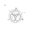
図1および図2から分かるように、本発明のフィルタ用メンブレン1が、複数種類の流体媒体、特に液体に含まれていて固体状態物(solid phase)を任意に包含する分子または粒子を分離またはフィルタ作用を行うようになっている。図示される実施形態においては、フィルタ用メンブレン1は管状タイプである。この実施例においては、フィルタ用メンブレン1は無機であって剛体のポーラス状支持部2を有しており、ポーラス状支持部2は、実施される分離作用に適した輸送抵抗(transfer resistance)を有する材料から形成されている。このポーラス状支持部2は無機材料、例えば金属酸化物、カーボンまたは金属から形成されている。この実施形態においては、ポーラス状支持部2は、中心の長手方向軸線Aに沿って延びる細長い形状をなしている。ポーラス状支持部2は多角形の断面、または図1および図2に示されるような円形断面を有している。従って、ポーラス状支持部2は円筒形状の外面21を有している。
As can be seen from FIG. 1 and FIG. 2, the
ポーラス状支持部2は少なくとも一つのチャネルを有するよう配置されており、図示される実施例においては、ポーラス状支持部2はポーラス状支持部の軸線Aに対して平行に延びる三つのチャネル3を有している。各チャネル3は、処理されるべき流体媒体に接触する少なくとも一つのセパレータ層4により被覆されている表面を有しており、前記流体媒体はチャネル3の内部を流れ方向fに流れる。流れ方向fはそのようなメンブレンのために入口部Eと出口部Sとを形成する役目を果たす。一つまたは複数のセパレータ層4の特性は、得られるべき分離またはフィルタ作用の能力(power)の関数、およびポーラス状支持部2に強力に結合する結合部を形成する性能(ability)の関数として選択され、それにより、流体媒体からの圧力がポーラス状支持部2まで伝達されるようになる。例えば、少なくとも一つの金属酸化物を含んでいて無機的フィルタ要素を製造するのに通常使用される懸濁液によって、一つまたは複数のセパレータ層を堆積させられる。ポーラス状支持部2に合併および結合させる目的、および二つまたはそれ以上のセパレータ層が存在する場合にはこれらセパレータ層の間を合併または結合させる目的で、一つまたは複数のセパレータ層を乾燥後に焼結させる。流体媒体の一部分はセパレータ層4とポーラス状支持部2とを通過し、それにより、流体の「浸透液」と呼ばれるこの処理された部分がポーラス状支持部2の外面21を通って流出するようになる。
The
本発明によれば、セパレータ層4の厚さeは、処理されるべき流体の流れ方向fに沿って減少する勾配を有している。従って、セパレータ層4の最も厚い部分はフィルタ用メンブレンの入口部Eに存在し、セパレータ層4の最も薄い部分はフィルタ用メンブレンの出口部Sに位置している。従って、セパレータ層4の厚さが異なるにもかかわらず浸透率が一定であるセパレータ層4の場合には、前記セパレータ層4とポーラス状支持部2とを通過する浸透液の流れがメンブレンに沿って一定であり、前記セパレータ層4の厚さeは圧力に比例して変化している。処理されるべき流体の圧力は、流体の流れ方向fに関して、すなわちメンブレンの入口部Eから出口部Sまで減少している。それゆえ前記セパレータ層の厚さ勾配は、浸透液流量がメンブレンの長さ部分全体にわたって一定になるように選択される。
According to the invention, the thickness e of the
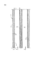
図2に示される実施例から明らかに分かるように、前記セパレータ層4の厚さ勾配は、処理されるべき流体の流れ方向fにほぼ連続的に減少している。図面における前記セパレータ層4とポーラス状支持部2との間の寸法比は実際の寸法比ではないことが分かる。本発明を示すためにセパレータ層4の縮尺を変更している。
As can be clearly seen from the embodiment shown in FIG. 2, the thickness gradient of the
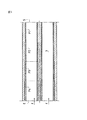
図3に示される他の実施形態においては、セパレータ層4の厚さ勾配は、段差部Piをなして、処理されるべき流体の流れ方向fに減少している。図示される実施形態においては、セパレータ層4は、処理されるべき流体の流れ方向に減少している厚さの段差部P1からP4を有している。セパレータ層4の段差部P1からP4の全ては、流れ方向に関してほぼ同一の長さであるのが好ましい。図示される実施形態においては、セパレータ層4の厚さは各段差部P1からP4においてほぼ一定である。従って、入口部Eに対して最も近い段差部P4におけるセパレータ層は、隣接する段差部P3におけるセパレータ層および他の連続的な段差部におけるセパレータ層よりも厚みが大きい。厚さが流れ方向に一定でなくて連続的に減少している各段差部P1からP4におけるセパレータ層であって、連続する段差部間の接合領域においてセパレータ層の厚さが不連続である場合を想定できる。
In another embodiment shown in FIG. 3, the thickness gradient of the
前述した実施例は、断面がほぼ卵形であって円筒形状のチャネルが形成されているメンブレンに関する。当然のことながら、様々な形状または多種の形状の一つまたはそれ以上のチャネルを有するメンブレンによって本発明を実施することができる。同様に、平面タイプのメンブレンを構成するために、ポーラス状ブロック内に配置されていて断面が多角形状の少なくとも一つのチャネル3を有するメンブレンに対して本発明を適用できるのは明らかである。この形式のメンブレンにおいては、ポーラス状支持部2は重ねられた(superposed)一連のチャネル3を有しており、これらチャネルのそれぞれは矩形の断面を有していて、これらチャネルの壁部はセパレータ層によって被覆されている。
The above-described embodiment relates to a membrane having a substantially oval cross section and formed with a cylindrical channel. Of course, the present invention can be implemented with membranes having one or more channels of various shapes or various shapes. Similarly, it is apparent that the present invention can be applied to a membrane having at least one
本発明は前述した形式のフィルタ用メンブレン1を製造する製造方法も提供する。以下の説明は、図3に示される形式のメンブレンを製造する製造方法に関する。そのような製造方法は、各チャネルを、ほぼ同一長さの一連のセグメントPi、例えば図示される実施例における四つのセグメントP1からP4に細分することを含む。次いで、各チャネル3の表面は、存在するセグメントPiの数に応じた堆積操作を行うことによってセパレータ層4により被覆される。図示される実施形態においては、セパレータ層4は、略粒子の形態をなしている複数の構成要素を含む懸濁液を使用して四つの連続的な堆積操作を行うことにより得られる。一般的または周知の方法においては、堆積部の厚さを懸濁液濃度および懸濁液とポーラス状支持部2との間の接触時間に関するパラメータによって制御する。本発明の方法においては、入口部Eからはじまる堆積部をチャネル3の表面上に形成する。堆積作用を受けるチャネルの長さは、連続的な各堆積操作に対して一つのセグメントごとに減少している。従って、四つのセグメントP1からP4を有するセパレータ層4からなる図示される実施形態においては、懸濁液は、最初にメンブレンの四つ全てのセグメントP1からP4上に堆積される。次いで、第二の堆積操作をセグメントP4からP2上に行って、第三の堆積操作をP4およびP3上に行って、次いで第四の堆積操作をセグメントP4上に行う。従って、メンブレンの一端Eから他端Sまで厚さ勾配が段差部をなして減少しているセパレータ層4を得ることができる。
The present invention also provides a manufacturing method for manufacturing a
ポーラス状支持部2を鉛直方向に配置して、得られるべきセパレータ層4を堆積させるための懸濁液をチャネル3に充填することを含む他の技術によって、本発明のメンブレンを製造することができる。ポーラス状支持部2に対して鉛直方向に堆積作用を行うことによって、ポーラス状支持部2の底部における圧力は、ポーラス状支持部2の高さに比例する量だけ頂部における圧力とは異なる。従って、このようにして形成される堆積部は「ビリヤードのキュー」の形状をなしており、それにより、ポーラス状支持部2の頂部からはじまるセパレータ層4の厚さは鉛直方向下方に増大している。堆積されるセパレータ層4の厚さは、ポーラス状支持部2と懸濁液との間の接触時間に応じて定まることが想起される。従って、堆積用懸濁液がチャネル内に存在する時間を次第に増大させるための設備(provision)を設けてチャネル3を次第に空にすることができる。これにより、厚さ勾配がポーラス状支持部の頂端部から底端部に向かって増大しているセパレータ層4を得ることができる。そのようなメンブレンは、入口部Eが支持部の底部とみなされて出口部Sが支持部の頂部とみなされるときに、厚さ勾配が流体の流れ方向に減少しているセパレータ層4を有する。
The membrane of the present invention can be produced by other techniques including placing the
当然のことながら、厚さ勾配を備えたセパレータ層を有するフィルタ用メンブレンを、前述した方法以外の堆積方法によって製造することができる。さらに、当該技術分野において一般的であって周知であり追加の説明は行わない技術を用いてセパレータ層を堆積させてもよい。 Naturally, a filter membrane having a separator layer with a thickness gradient can be produced by a deposition method other than the method described above. Further, the separator layer may be deposited using techniques that are common and well known in the art and will not be described further.
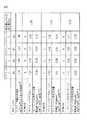
本発明のフィルタ用メンブレン1は、メンブレンを脆くするあらゆる危険性を伴うことなしに、処理されるべき流体の流れ方向に減少するセパレータ層の厚さ勾配を決定することによって、浸透液流量を比較的単純にメンブレンに沿って一定にすることができる。この特性は、図4および図5の表を比較することによって明らかとなる。
The
後述する実施形態においては、外径が10mmであって内径が6mmであって長さが1200mmの単一のチャネルを有するポーラス状支持部2を使用する。ポーラス状支持部は平均等価直径(mean equivalent pore diameter)が5マイクロメートルの細孔を有している。酸化チタンがチャネルの壁部に堆積されて、それにより、焼結後に、細孔の平均等価直径が1.5マイクロメートルである堆積部が得られるようになる。堆積部の均一性を解析するために、前述した方法で形成されるメンブレン1は、均一な長さの四つのセグメントP1からP4に切断され、各セグメントは水に対する浸透率を測定される。
In an embodiment described later, a
図4の表は、流体としての水および従来技術に基づくメンブレンのセグメントに基づいている。この表は、
細孔の平均等価直径が1.5マイクロメートルであるセパレータ層の厚さ、
および、セパレータ層の浸透率を示している。
この表を見ると、セパレータ層の厚さの値、従って浸透率の値が、メンブレンの複数のセグメントに対して比較的均一になっているのが分かる。
The table in FIG. 4 is based on water as the fluid and membrane segments based on the prior art. This table
The thickness of the separator layer, wherein the average equivalent diameter of the pores is 1.5 micrometers,
And the permeability of the separator layer is shown.
Looking at this table, it can be seen that the thickness value of the separator layer, and thus the permeability value, is relatively uniform for multiple segments of the membrane.
図5の表は、図3に関して前述した形式のセパレータ層4によって被覆されたチャネルを有するメンブレンのセパレータ層に関する厚さおよび浸透率の特性を示している。従って、本発明のそのようなメンブレンは、段差部P1からP4に対応する四つのセグメントを形成するために、四つの連続的な堆積操作を行うことによって形成される。
The table of FIG. 5 shows the thickness and permeability characteristics for a membrane separator layer having a channel covered by a
セグメントP1からP4を比較すると、セパレータ層4の厚さは流体の流れ方向、すなわち、段差部P4から段差部P1に向かう方向に減少している。さらに、セパレータ層4の浸透率はほぼ一定であることが分かる。
図5の表はまた、各セグメント、および三つの異なる損失ヘッドの値に対応する三つの異なる流速も示している。損失ヘッドは、平均圧力、浸透液流量、および本発明のメンブレンの入口側セグメントの流量と出口側セグメントの流量との比である。本発明の目的は、メンブレン内の表面要素が検討中であるにもかかわらず、ほぼ一定の浸透液流量をあらゆる機械的システムから独立して得ることができることを達成することである。入口側セグメントの流量/出口側セグメントの流量の比は、1に極めて近くて、通常のメンブレンによって得られて結果が図4の表に示される流量の比よりも小さい。
Compared from the segment P 1 to P 4, the thickness of the
The table in FIG. 5 also shows three different flow rates corresponding to each segment and three different loss head values. The loss head is the average pressure, the permeate flow rate, and the ratio of the flow rate of the inlet segment and the outlet segment of the membrane of the present invention. The object of the present invention is to achieve that a substantially constant permeate flow rate can be obtained independently of any mechanical system, regardless of the surface elements in the membrane under consideration. The inlet segment flow rate / outlet segment flow rate ratio is very close to 1 and is smaller than the flow rate ratio obtained with a normal membrane and the results shown in the table of FIG.
本発明のメンブレンの場合に出口側セグメントP1における流量に対する入口側セグメントP4における流量の比を検討すると、出口側セグメントにおける流量は入口側セグメントにおける流量よりもわずかに大きい(比は1よりも小さい)。これらの結果は、浸透液流量がメンブレン全体に沿ってほぼ等しいので、厚さ勾配が流体の流れ方向に減少しているセパレータ層を設けることが有効であることを示している。出口側セグメントの流量に対する入口側セグメントの流量の比が1より小さい値であるということは、セパレータ層の厚さが流体によって及ぼされる圧力に比較してわずかに大きいことによって説明されうる。セパレータ層4の厚さ勾配に対して選択される値は、メンブレンを操作するパラメータを考慮することによって選択される。このようなメンブレンによって、メンブレンの全長さ部分に沿って一定またはほぼ一定の浸透液流量を得ることができる。言い換えれば、セパレータ層4の厚さ勾配は、メンブレン全体に沿って一定の浸透液流量を得るために、チャネルに沿って流れる流体の圧力勾配の関数として選択される。メンブレンの或るセクションにより示される最大浸透液流量とメンブレンの他のセクションにより示される最小浸透液流量との間の差が20%よりも小さい量だけ異なっているので、浸透液流量はメンブレン全体に沿って一定であるとみなされることが分かる。従って、最低値を示すセクションの浸透液流量に対する、最高値を示すセクションの浸透液流量の比は1から1.2の範囲に在る。
Considering the ratio of the flow rate at the inlet end segment P 4 to the flow rate at the outlet end segment P 1 in the case of the membranes of the present invention, the flow rate at the outlet end segment slightly larger than the flow rate at the inlet end segment large (ratio than 1 small). These results show that it is effective to provide a separator layer in which the thickness gradient decreases in the fluid flow direction because the permeate flow rate is approximately equal along the entire membrane. The ratio of the inlet segment flow rate to the outlet segment flow rate being less than 1 can be explained by the fact that the thickness of the separator layer is slightly larger compared to the pressure exerted by the fluid. The value selected for the thickness gradient of the
図5においては、処理されるべき流体の速度Vによって、浸透液流量の比が入口側セグメントとで出口側セグメントとの間において変化している。従って、厚さ勾配は与えられた流体の流速に対して決定される。図示される実施形態においては、セパレータ層4の厚さは、毎秒5メートル(5m/s)である流体の流速に特に適している。しかしながら、そのようなメンブレンは、処理されるべき流体の流速が異なる値である場合でさえ有効で有り続けることが分かる。
In FIG. 5, the permeate flow ratio varies between the inlet segment and the outlet segment depending on the velocity V of the fluid to be treated. Thus, the thickness gradient is determined for a given fluid flow rate. In the illustrated embodiment, the thickness of the
図5においては、セパレータ層4の浸透率とセグメントの流量とを比較することによって、ポーラス状支持部2の浸透率がセパレータ層4の浸透率よりも大きいことが分かる。通常の方法によって、ポーラス状支持部2は、第一に輸送圧力に対する機械的強度を提供する必要があり、第二にフィルタ作用においてブレーキ要素が形成されるのを妨げるのに十分な浸透性を有する必要がある。
In FIG. 5, by comparing the permeability of the
A 長手方向軸線
E 入口部
Pi 段差部
S 出口部
1 フィルタ用メンブレン
2 ポーラス状支持部
3 チャネル
4 セパレータ層
A Longitudinal axis E Inlet part Pi step part
Claims (15)
各チャネル(3)の長さ部分を、ほぼ等しい長さである一連のセグメント(Pi)まで細分することを含み、
さらに、
前記チャネルの入口端部からはじまる堆積操作を、存在するセグメントの数に応じて行い、処理されるチャネルの長さを連続的な各堆積操作に対して一つのセグメントごとに減少させることによって、前記セパレータ層(4)により前記チャネル(3)の表面を被覆することを含む、請求項12に記載のフィルタ用メンブレン製造方法。 In the filter membrane manufacturing method,
Subdividing the length of each channel (3) into a series of segments (P i ) of approximately equal length;
further,
The deposition operation starting from the inlet end of the channel is performed as a function of the number of segments present, and the length of the channel being processed is reduced by one segment for each successive deposition operation. The method for producing a filter membrane according to claim 12, comprising coating the surface of the channel (3) with a separator layer (4).
前記ポーラス状支持部(2)を鉛直方向に配置することと、
前記セパレータ層(4)を堆積させるために、
各チャネル(3)を懸濁液でもって充填することと、次第に増大する時間の長さに対して、堆積用懸濁液を前記チャネルの内部に残すために、各チャネル(3)を次第に空にすることとによって、前記ポーラス状支持部(2)上に前記セパレータ層(4)を堆積させることを含み、その結果、前記流れ方向(f)に減少している厚さ勾配を有するセパレータ層(4)を得ることができ、該厚さ勾配は前記ポーラス状支持部(2)の底端部から頂端部に向かって延びているとみなされる請求項9または10のいずれか一項に記載のフィルタ用メンブレン製造方法。 In the filter membrane manufacturing method,
Arranging the porous support (2) in a vertical direction;
In order to deposit the separator layer (4),
For filling each channel (3) with suspension and increasing the length of time, each channel (3) is gradually emptied to leave the deposition suspension inside the channel. By depositing the separator layer (4) on the porous support (2), so that the separator layer has a thickness gradient decreasing in the flow direction (f) 11. (4) can be obtained, wherein the thickness gradient is considered to extend from the bottom end of the porous support (2) towards the top end. Filter membrane manufacturing method.
前記流体は、請求項1から7のいずれか一項に記載のフィルタ用メンブレンの前記チャネル内において、前記セパレータ層の最も厚い部分に対応する前記フィルタ用メンブレンの入口から前記セパレータ層の最も薄い部分に対応する前記フィルタ用メンブレンの出口まで流れるようにした、処理方法。 In a processing method for processing a fluid,
The thinnest portion of the separator layer from the inlet of the filter membrane corresponding to the thickest portion of the separator layer in the channel of the filter membrane according to any one of claims 1 to 7 The processing method which made it flow to the exit of the said membrane for filters corresponding to.
Applications Claiming Priority (2)
| Application Number | Priority Date | Filing Date | Title |
|---|---|---|---|
| FR9910294A FR2797198B1 (en) | 1999-08-04 | 1999-08-04 | MEMBRANE FOR TANGENTIAL FILTRATION AND ITS MANUFACTURING METHOD |
| FR9910294 | 1999-08-04 |
Related Parent Applications (1)
| Application Number | Title | Priority Date | Filing Date |
|---|---|---|---|
| JP2000235886A Division JP2001062266A (en) | 1999-08-04 | 2000-08-03 | Membrane for filter and production of membrane for filter |
Publications (2)
| Publication Number | Publication Date |
|---|---|
| JP2010069483A true JP2010069483A (en) | 2010-04-02 |
| JP5266190B2 JP5266190B2 (en) | 2013-08-21 |
Family
ID=9548998
Family Applications (2)
| Application Number | Title | Priority Date | Filing Date |
|---|---|---|---|
| JP2000235886A Withdrawn JP2001062266A (en) | 1999-08-04 | 2000-08-03 | Membrane for filter and production of membrane for filter |
| JP2009268712A Expired - Lifetime JP5266190B2 (en) | 1999-08-04 | 2009-11-26 | Filter membrane and filter membrane manufacturing method |
Family Applications Before (1)
| Application Number | Title | Priority Date | Filing Date |
|---|---|---|---|
| JP2000235886A Withdrawn JP2001062266A (en) | 1999-08-04 | 2000-08-03 | Membrane for filter and production of membrane for filter |
Country Status (10)
| Country | Link |
|---|---|
| US (2) | US6499606B1 (en) |
| EP (1) | EP1074291B1 (en) |
| JP (2) | JP2001062266A (en) |
| AT (1) | ATE308373T1 (en) |
| CA (1) | CA2316742C (en) |
| DE (1) | DE60023607T2 (en) |
| DK (1) | DK1074291T3 (en) |
| ES (1) | ES2251952T3 (en) |
| FR (1) | FR2797198B1 (en) |
| NZ (1) | NZ506118A (en) |
Cited By (2)
| Publication number | Priority date | Publication date | Assignee | Title |
|---|---|---|---|---|
| CN102374211A (en) * | 2010-08-23 | 2012-03-14 | 贺勍 | Cascade combined type coarse and fine granule grading filter cartridge and combination method thereof |
| JP2020082011A (en) * | 2018-11-29 | 2020-06-04 | 京セラ株式会社 | Gas separation member and gas separation device |
Families Citing this family (62)
| Publication number | Priority date | Publication date | Assignee | Title |
|---|---|---|---|---|
| EP1736234A3 (en) | 1996-12-20 | 2007-06-13 | Siemens Water Technologies Corp. | Method for scouring fouled membranes |
| FR2797198B1 (en) * | 1999-08-04 | 2002-05-03 | Tami Ind | MEMBRANE FOR TANGENTIAL FILTRATION AND ITS MANUFACTURING METHOD |
| AU2001274081A1 (en) * | 2000-06-10 | 2001-12-24 | Sartorius Ag | Device for cross-flow filtration of liquids |
| AUPR421501A0 (en) | 2001-04-04 | 2001-05-03 | U.S. Filter Wastewater Group, Inc. | Potting method |
| AUPR692401A0 (en) | 2001-08-09 | 2001-08-30 | U.S. Filter Wastewater Group, Inc. | Method of cleaning membrane modules |
| DE10159191B4 (en) * | 2001-11-29 | 2006-05-11 | Leibniz-Institut Für Polymerforschung Dresden E.V. | Modified hollow fiber membrane materials and methods for their modification |
| AUPS300602A0 (en) | 2002-06-18 | 2002-07-11 | U.S. Filter Wastewater Group, Inc. | Methods of minimising the effect of integrity loss in hollow fibre membrane modules |
| US7938966B2 (en) | 2002-10-10 | 2011-05-10 | Siemens Water Technologies Corp. | Backwash method |
| FR2846255B1 (en) * | 2002-10-25 | 2005-01-28 | Tech Avancees & Membranes Ind | TANGENTIAL FILTRATION MEMBRANE AND METHOD OF MANUFACTURING THE SAME |
| AU2002953111A0 (en) | 2002-12-05 | 2002-12-19 | U. S. Filter Wastewater Group, Inc. | Mixing chamber |
| JP4358538B2 (en) * | 2003-03-17 | 2009-11-04 | 日本碍子株式会社 | Ceramic filter |
| JP4367694B2 (en) * | 2003-08-13 | 2009-11-18 | 日本碍子株式会社 | Permselective membrane reactor |
| NZ545206A (en) | 2003-08-29 | 2009-03-31 | Siemens Water Tech Corp | Backwash |
| US7276163B2 (en) * | 2003-10-01 | 2007-10-02 | Ceramem Corporation | Membrane devices with controlled transmembrane pressure and method of use |
| US20050092683A1 (en) * | 2003-10-31 | 2005-05-05 | Goldsmith Robert L. | Membrane devices for pervaporation, gas separations, and perstraction with permeate and sweep fluid conduit and method of use |
| NZ546959A (en) | 2003-11-14 | 2008-03-28 | Siemens Water Tech Corp | Improved cleaning method for a porous membrane filtration module |
| US7392811B2 (en) * | 2004-02-23 | 2008-07-01 | Ecolab Inc. | Delivery head for multiple phase treatment composition, vessel including a delivery head, and method for treating a vessel interior surface |
| US7220358B2 (en) * | 2004-02-23 | 2007-05-22 | Ecolab Inc. | Methods for treating membranes and separation facilities and membrane treatment composition |
| US7247210B2 (en) * | 2004-02-23 | 2007-07-24 | Ecolab Inc. | Methods for treating CIP equipment and equipment for treating CIP equipment |
| WO2005092799A1 (en) | 2004-03-26 | 2005-10-06 | U.S. Filter Wastewater Group, Inc. | Process and apparatus for purifying impure water using microfiltration or ultrafiltration in combination with reverse osmosis |
| CN101426565B (en) | 2004-04-22 | 2012-04-18 | 西门子工业公司 | Filtration apparatus comprising a membrane bioreactor and a treatment vessel for digesting organic materials |
| FR2869241B1 (en) * | 2004-04-23 | 2006-07-21 | Tech Avancees & Membranes Ind | MODIFIED POROSITY SUPPORT AND MEMBRANE FOR THE TANGENTIAL FILTRATION OF A FLUID |
| EP1789164B1 (en) | 2004-08-20 | 2013-07-03 | Siemens Industry, Inc. | Square mbr manifolding system |
| CA2579168C (en) | 2004-09-07 | 2015-06-23 | Siemens Water Technologies Corp. | Membrane filtration with reduced volume cleaning step |
| CN101039739B (en) | 2004-09-14 | 2014-10-08 | 伊沃夸水处理技术有限责任公司 | Methods and apparatus for removing solids from a membrane module |
| WO2006029465A1 (en) | 2004-09-15 | 2006-03-23 | Siemens Water Technologies Corp. | Continuously variable aeration |
| US8758622B2 (en) | 2004-12-24 | 2014-06-24 | Evoqua Water Technologies Llc | Simple gas scouring method and apparatus |
| SG150505A1 (en) | 2004-12-24 | 2009-03-30 | Siemens Water Tech Corp | Cleaning in membrane filtration systems |
| JP2006181506A (en) * | 2004-12-28 | 2006-07-13 | Kobelco Eco-Solutions Co Ltd | Hollow fiber module |
| CA2605757A1 (en) | 2005-04-29 | 2006-11-09 | Siemens Water Technologies Corp. | Chemical clean for membrane filter |
| SG140229A1 (en) | 2005-08-22 | 2008-03-28 | Siemens Water Tech Corp | An assembly for water filtration using a tube manifold to minimise backwash |
| WO2007044415A2 (en) | 2005-10-05 | 2007-04-19 | Siemens Water Technologies Corp. | Method and apparatus for treating wastewater |
| JP2007229564A (en) * | 2006-02-28 | 2007-09-13 | Ngk Insulators Ltd | Manufacturing method of ceramic filter |
| JP4760469B2 (en) * | 2006-03-24 | 2011-08-31 | トヨタ自動車株式会社 | Humidifier and fuel cell system |
| US8293098B2 (en) | 2006-10-24 | 2012-10-23 | Siemens Industry, Inc. | Infiltration/inflow control for membrane bioreactor |
| FR2914197B1 (en) * | 2007-03-26 | 2009-12-11 | Applexion | TANGENTIAL FILTRATION SUPPORT AND PROCESS FOR PREPARING THE SAME |
| US8318028B2 (en) | 2007-04-02 | 2012-11-27 | Siemens Industry, Inc. | Infiltration/inflow control for membrane bioreactor |
| US9764288B2 (en) | 2007-04-04 | 2017-09-19 | Evoqua Water Technologies Llc | Membrane module protection |
| EP3395433A1 (en) | 2007-05-29 | 2018-10-31 | Evoqua Water Technologies LLC | Membrane cleaning with pulsed airlift pump |
| US20090000475A1 (en) * | 2007-06-29 | 2009-01-01 | Curtis Robert Fekety | Zeolite membrane structures and methods of making zeolite membrane structures |
| US20090166171A1 (en) * | 2008-01-02 | 2009-07-02 | Total Separation Solutions Llc | Trifunctional membrane tube arrays |
| JP2013500144A (en) | 2008-07-24 | 2013-01-07 | シーメンス インダストリー インコーポレイテッド | Method and filtration system for providing structural support to a filtration membrane module array in a filtration system |
| CA2734796A1 (en) | 2008-08-20 | 2010-02-25 | Siemens Water Technologies Corp. | Improved membrane system backwash energy efficiency |
| US7875176B2 (en) * | 2009-03-06 | 2011-01-25 | Porous Media Corporation | Membrane module for fluid filtration |
| AU2010101488B4 (en) | 2009-06-11 | 2013-05-02 | Evoqua Water Technologies Llc | Methods for cleaning a porous polymeric membrane and a kit for cleaning a porous polymeric membrane |
| ES2738898T3 (en) | 2010-04-30 | 2020-01-27 | Evoqua Water Tech Llc | Fluid flow distribution device |
| DE102010035698A1 (en) * | 2010-08-27 | 2012-03-01 | Innowa Gmbh | Multichannel membrane |
| WO2012040412A1 (en) | 2010-09-24 | 2012-03-29 | Siemens Industry, Inc. | Fluid control manifold for membrane filtration system |
| ES2478966T3 (en) * | 2010-10-26 | 2014-07-23 | Dow Global Technologies Llc | Spiral wound module that includes a membrane sheet with regions that have different permeabilities |
| SG11201401089PA (en) | 2011-09-30 | 2014-04-28 | Evoqua Water Technologies Llc | Improved manifold arrangement |
| KR20140097140A (en) | 2011-09-30 | 2014-08-06 | 에보쿠아 워터 테크놀로지스 엘엘씨 | Isolation valve |
| AU2013280452B2 (en) | 2012-06-28 | 2017-07-20 | Evoqua Water Technologies Llc | A potting method |
| US9962865B2 (en) | 2012-09-26 | 2018-05-08 | Evoqua Water Technologies Llc | Membrane potting methods |
| US9764289B2 (en) | 2012-09-26 | 2017-09-19 | Evoqua Water Technologies Llc | Membrane securement device |
| EP2900356A1 (en) | 2012-09-27 | 2015-08-05 | Evoqua Water Technologies LLC | Gas scouring apparatus for immersed membranes |
| AU2014329869B2 (en) | 2013-10-02 | 2018-06-14 | Evoqua Water Technologies Llc | A method and device for repairing a membrane filtration module |
| KR102045100B1 (en) * | 2015-04-14 | 2019-11-14 | 주식회사 엘지화학 | Anti-telescoping device for membrane separation device |
| FR3036626B1 (en) | 2015-05-29 | 2019-12-20 | Technologies Avancees Et Membranes Industrielles | SEPARATION ELEMENT WITH A THREE-DIMENSIONAL CIRCULATION NETWORK FOR THE FLUID MEDIUM TO BE TREATED |
| US10322375B2 (en) | 2015-07-14 | 2019-06-18 | Evoqua Water Technologies Llc | Aeration device for filtration system |
| CN106422473B (en) * | 2016-12-06 | 2019-04-12 | 无锡优耐特净化装备有限公司 | Filter core |
| US10940444B2 (en) | 2017-03-16 | 2021-03-09 | University Of Maryland, College Park | Membranes and methods of use thereof |
| CN114307688B (en) * | 2020-09-29 | 2023-02-14 | 三达膜科技(厦门)有限公司 | Membrane thickness gradient distribution ceramic filtering membrane and preparation method thereof |
Citations (5)
| Publication number | Priority date | Publication date | Assignee | Title |
|---|---|---|---|---|
| JPS61238315A (en) * | 1985-04-12 | 1986-10-23 | Ngk Insulators Ltd | Preparation of double-layered filter |
| JPH0796152A (en) * | 1993-06-24 | 1995-04-11 | Toray Ind Inc | Gradient hollow-fiber membrane and its production |
| JPH07116480A (en) * | 1993-10-27 | 1995-05-09 | Noritake Co Ltd | Monolith type ceramic filter |
| JPH10176519A (en) * | 1996-12-18 | 1998-06-30 | Sumitomo Electric Ind Ltd | Particulate trap for diesel engine |
| JPH1157421A (en) * | 1997-04-09 | 1999-03-02 | Ceramiques Technique:Soc | Fine porous support with permeability gradient and manufacturing of fine porous support |
Family Cites Families (9)
| Publication number | Priority date | Publication date | Assignee | Title |
|---|---|---|---|---|
| US4276071A (en) * | 1979-12-03 | 1981-06-30 | General Motors Corporation | Ceramic filters for diesel exhaust particulates |
| US4390355A (en) * | 1982-02-02 | 1983-06-28 | General Motors Corporation | Wall-flow monolith filter |
| US4423090A (en) * | 1982-02-02 | 1983-12-27 | General Motors Corporation | Method of making wall-flow monolith filter |
| EP0225402A1 (en) * | 1985-11-05 | 1987-06-16 | Nippondenso Co., Ltd. | Porous ceramic structure |
| ATE133752T1 (en) * | 1993-03-26 | 1996-02-15 | Siemens Ag | CATALYST FOR REDUCING NITROGEN OXIDE IN THE EXHAUST GAS OF A COMBUSTION ENGINE |
| FR2720953B1 (en) * | 1994-06-08 | 1996-08-30 | Tami Ind | Multichannel inorganic element for the filtration of a fluid. |
| JP3647501B2 (en) * | 1995-03-31 | 2005-05-11 | アマノ株式会社 | Filter for dust collector |
| FR2741821B1 (en) * | 1995-12-05 | 1998-02-20 | Tami Ind | INORGANIC FILTRATION TUBULAR ELEMENT HAVING INCREASED FILTRATION SURFACE AND MECHANICAL STRENGTH |
| FR2797198B1 (en) * | 1999-08-04 | 2002-05-03 | Tami Ind | MEMBRANE FOR TANGENTIAL FILTRATION AND ITS MANUFACTURING METHOD |
-
1999
- 1999-08-04 FR FR9910294A patent/FR2797198B1/en not_active Expired - Fee Related
-
2000
- 2000-07-27 US US09/627,068 patent/US6499606B1/en not_active Expired - Lifetime
- 2000-08-02 EP EP00420171A patent/EP1074291B1/en not_active Expired - Lifetime
- 2000-08-02 DE DE60023607T patent/DE60023607T2/en not_active Expired - Lifetime
- 2000-08-02 AT AT00420171T patent/ATE308373T1/en active
- 2000-08-02 DK DK00420171T patent/DK1074291T3/en active
- 2000-08-02 ES ES00420171T patent/ES2251952T3/en not_active Expired - Lifetime
- 2000-08-02 NZ NZ506118A patent/NZ506118A/en not_active IP Right Cessation
- 2000-08-03 JP JP2000235886A patent/JP2001062266A/en not_active Withdrawn
- 2000-08-03 CA CA002316742A patent/CA2316742C/en not_active Expired - Lifetime
-
2002
- 2002-11-18 US US10/295,841 patent/US6780466B2/en not_active Expired - Lifetime
-
2009
- 2009-11-26 JP JP2009268712A patent/JP5266190B2/en not_active Expired - Lifetime
Patent Citations (5)
| Publication number | Priority date | Publication date | Assignee | Title |
|---|---|---|---|---|
| JPS61238315A (en) * | 1985-04-12 | 1986-10-23 | Ngk Insulators Ltd | Preparation of double-layered filter |
| JPH0796152A (en) * | 1993-06-24 | 1995-04-11 | Toray Ind Inc | Gradient hollow-fiber membrane and its production |
| JPH07116480A (en) * | 1993-10-27 | 1995-05-09 | Noritake Co Ltd | Monolith type ceramic filter |
| JPH10176519A (en) * | 1996-12-18 | 1998-06-30 | Sumitomo Electric Ind Ltd | Particulate trap for diesel engine |
| JPH1157421A (en) * | 1997-04-09 | 1999-03-02 | Ceramiques Technique:Soc | Fine porous support with permeability gradient and manufacturing of fine porous support |
Cited By (3)
| Publication number | Priority date | Publication date | Assignee | Title |
|---|---|---|---|---|
| CN102374211A (en) * | 2010-08-23 | 2012-03-14 | 贺勍 | Cascade combined type coarse and fine granule grading filter cartridge and combination method thereof |
| JP2020082011A (en) * | 2018-11-29 | 2020-06-04 | 京セラ株式会社 | Gas separation member and gas separation device |
| JP7118871B2 (en) | 2018-11-29 | 2022-08-16 | 京セラ株式会社 | Gas separation member and gas separation device |
Also Published As
| Publication number | Publication date |
|---|---|
| FR2797198A1 (en) | 2001-02-09 |
| US20030070981A1 (en) | 2003-04-17 |
| EP1074291A1 (en) | 2001-02-07 |
| DE60023607D1 (en) | 2005-12-08 |
| CA2316742C (en) | 2009-03-31 |
| NZ506118A (en) | 2002-02-01 |
| ES2251952T3 (en) | 2006-05-16 |
| US6499606B1 (en) | 2002-12-31 |
| US6780466B2 (en) | 2004-08-24 |
| JP5266190B2 (en) | 2013-08-21 |
| DE60023607T2 (en) | 2006-08-10 |
| JP2001062266A (en) | 2001-03-13 |
| EP1074291B1 (en) | 2005-11-02 |
| FR2797198B1 (en) | 2002-05-03 |
| CA2316742A1 (en) | 2001-02-04 |
| ATE308373T1 (en) | 2005-11-15 |
| DK1074291T3 (en) | 2006-03-13 |
Similar Documents
| Publication | Publication Date | Title |
|---|---|---|
| JP5266190B2 (en) | Filter membrane and filter membrane manufacturing method | |
| US5454947A (en) | Ceramic filter element for tangential flow filtration of liquids and gases | |
| US4781831A (en) | Cross-flow filtration device with filtrate flow conduits and method of forming same | |
| US5607586A (en) | Multichannel inorganic element for filtering a fluid | |
| US5641332A (en) | Filtraion device with variable thickness walls | |
| JP7093778B2 (en) | Tangential flow separation element with built-in bending flow path | |
| KR101937630B1 (en) | Substrate geometry for a filtration membrane | |
| WO2006043884A1 (en) | Permeate tube | |
| JP2018516168A (en) | Monolithic column structure for separating fluid media | |
| JP4177813B2 (en) | Tangential filtration membrane and method for producing the same | |
| JP2000354746A (en) | Filter using ceramic porous body | |
| JPH04215825A (en) | Manufacture of membrane for micro- filtration, ultra filtration, super evaporation, reverse osmosis, of suspension and emulsion or gas separation | |
| JP6953314B2 (en) | Separation element with 3D flow network for flow medium to be processed | |
| JP2007533443A (en) | Supports and membranes with variable porosity for tangential flow filtration | |
| EP0310632A1 (en) | Cross-flow filtration device and method of making. | |
| KR20230042300A (en) | Variable Rate Patterns in Cross-Flow Filtration | |
| JP2002143655A (en) | Ceramic filter and producing method of ceramic filter | |
| US20040188342A1 (en) | Filter | |
| WO2010119258A1 (en) | Tubular filter with stellated inner cross-section | |
| US10814281B2 (en) | Separation element with improved channelling of the filtrate | |
| US20230405529A1 (en) | Element for separating a liquid medium with high parietal shear stress | |
| JP2010110743A (en) | Concentrator and concentration method |
Legal Events
| Date | Code | Title | Description |
|---|---|---|---|
| A977 | Report on retrieval |
Free format text: JAPANESE INTERMEDIATE CODE: A971007 Effective date: 20120810 |
|
| A131 | Notification of reasons for refusal |
Free format text: JAPANESE INTERMEDIATE CODE: A131 Effective date: 20120821 |
|
| A521 | Request for written amendment filed |
Free format text: JAPANESE INTERMEDIATE CODE: A523 Effective date: 20121031 |
|
| TRDD | Decision of grant or rejection written | ||
| A01 | Written decision to grant a patent or to grant a registration (utility model) |
Free format text: JAPANESE INTERMEDIATE CODE: A01 Effective date: 20130402 |
|
| A61 | First payment of annual fees (during grant procedure) |
Free format text: JAPANESE INTERMEDIATE CODE: A61 Effective date: 20130502 |
|
| R150 | Certificate of patent or registration of utility model |
Ref document number: 5266190 Country of ref document: JP Free format text: JAPANESE INTERMEDIATE CODE: R150 Free format text: JAPANESE INTERMEDIATE CODE: R150 |
|
| R250 | Receipt of annual fees |
Free format text: JAPANESE INTERMEDIATE CODE: R250 |
|
| R250 | Receipt of annual fees |
Free format text: JAPANESE INTERMEDIATE CODE: R250 |
|
| R250 | Receipt of annual fees |
Free format text: JAPANESE INTERMEDIATE CODE: R250 |
|
| R250 | Receipt of annual fees |
Free format text: JAPANESE INTERMEDIATE CODE: R250 |
|
| R250 | Receipt of annual fees |
Free format text: JAPANESE INTERMEDIATE CODE: R250 |
|
| EXPY | Cancellation because of completion of term |