JP2010068331A - Imaging device and imaging method - Google Patents
Imaging device and imaging method Download PDFInfo
- Publication number
- JP2010068331A JP2010068331A JP2008233590A JP2008233590A JP2010068331A JP 2010068331 A JP2010068331 A JP 2010068331A JP 2008233590 A JP2008233590 A JP 2008233590A JP 2008233590 A JP2008233590 A JP 2008233590A JP 2010068331 A JP2010068331 A JP 2010068331A
- Authority
- JP
- Japan
- Prior art keywords
- pixel
- output
- data
- filter
- yuv
- Prior art date
- Legal status (The legal status is an assumption and is not a legal conclusion. Google has not performed a legal analysis and makes no representation as to the accuracy of the status listed.)
- Pending
Links
Images


Abstract
Description
本発明は、デジタルスチルカメラ、デジタルビデオカメラ等の撮像装置および撮像方法に関し、特に撮影画像のダイナミックレンジを拡大することができる撮像装置および撮像方法に関する。 The present invention relates to an imaging apparatus and an imaging method such as a digital still camera and a digital video camera, and more particularly to an imaging apparatus and an imaging method that can expand a dynamic range of a captured image.
銀塩写真フィルムを用いる従来の銀塩カメラで撮影される画像のダイナミックレンジに比べ、CCD等の固体撮像素子を有するデジタルスチルカメラやデジタルビデオカメラ等で撮影される画像のダイナミックレンジは極めて狭い。ダイナミックレンジが狭いと、被写体の暗い部分は「黒つぶれ」といわれる現象が発生し、逆に被写体の明るい部分は「白とび」といわれる現象が発生して画像品質が低下する。 Compared to the dynamic range of images taken with a conventional silver salt camera using a silver salt photographic film, the dynamic range of images taken with a digital still camera or a digital video camera having a solid-state image sensor such as a CCD is extremely narrow. When the dynamic range is narrow, a phenomenon called “blackout” occurs in the dark part of the subject, and conversely, a phenomenon called “overexposure” occurs in the bright part of the subject, and the image quality deteriorates.
そこで、CCD等の固体撮像素子で撮像される画像のダイナミックレンジを拡大するために、例えば、同一被写体に対して露光量を変えて複数回の撮影を行い、露光量の異なる複数の画像を取得し、これらの画像を加算してダイナミックレンジが拡大された合成画像を生成する技術が従来より知られている(例えば、特許文献1参照)。
ところで、ダイナミックレンジを拡大するために、前記特許文献1のように露光量を変えて複数回の撮影を行う方法では、移動物体の被写体を撮影したりすると、被写体が2重にずれた画像になり、正しく画像を合成できないことがある。
By the way, in order to expand the dynamic range, in the method of performing photographing a plurality of times while changing the exposure amount as in the above-mentioned
そこで、本発明は、露光量を変え複数回の撮影を行って画像を合成することなく、1回の撮影によってダイナミックレンジを拡大することができる撮像装置および撮像方法を提供することを目的とする。 SUMMARY OF THE INVENTION Accordingly, an object of the present invention is to provide an imaging apparatus and an imaging method capable of expanding the dynamic range by one shooting without changing the exposure amount and performing a plurality of shootings to combine images. .
前記目的を達成するために請求項1に記載の撮像装置は、光学系を通して入射される被写体像を複数の画素を有する受光面に受光して電気信号に変換するとともに、前記各画素の前面側に複数色の色分解フィルタが配置された撮像素子と、前記各画素からの出力を検出するとともに、検出した画素出力に基づいて周辺のある特定色のフィルタが配置された画素からの出力が、入出力特性が線形でなくなる飽和領域に達しているか否かを判定する周辺画素飽和判定手段と、前記周辺画素飽和判定手段により、前記特定色のフィルタが配置された画素からの出力が前記飽和領域に達していると判定した場合に、その周囲の前記特定色以外のフィルタが配置された画素からの出力に基づいて、前記特定色のフィルタが配置された画素からの出力を補正する飽和画素出力補正処理手段と、前記飽和画素出力補正処理手段により前記補正処理された画素出力から生成される第1YUVデータと、前記飽和画素出力補正処理手段で前記補正処理を行うことなく前記飽和領域に達している画素出力から生成される第2YUVデータとを取り込み、前記第1YUVデータから取り出した輝度データと、前記第2YUVデータから取り出した色差データとを合成した第3YUVデータを生成するYUV合成手段と、を有することを特徴としている。
In order to achieve the above object, an imaging apparatus according to
請求項2に記載の撮像装置は、前記周辺画素飽和判定手段で前記各画素の出力を検出する際の処理単位は、水平・垂直方向に2×2画素の大きさであることを特徴としている。
The imaging apparatus according to
請求項3に記載の撮像装置は、前記特定色のフィルタが配置された画素の出力に対して、前記飽和領域に達しているときに前記補正させる動作を、選択して実行させるための動作選択手段を備えていることを特徴としている。
The image pickup apparatus according to
請求項4に記載の撮像装置は、前記特定色のフィルタが配置された画素の出力が前記飽和領域に達している場合に前記飽和画素出力補正処理手段から出力される、前記画素出力の飽和領域を表現可能な第1のビット数から前記画素出力の飽和レベルを超えて表現可能な第2のビット数に一度拡張された画素出力のデータを、再度前記第1のビット数に圧縮するビット圧縮変換手段を備え、前記ビット圧縮変換手段は、前記飽和領域以上における画素出力に対応したデータに対する圧縮率よりも、前記飽和領域以下における画素出力に対応したデータに対する圧縮率を小さくして圧縮することを特徴としている。
The imaging device according to
請求項5に記載の撮像装置は、前記飽和領域以下で低輝度レベルにおける画素出力に対応したデータに対しては、前記ビット圧縮変換手段でビット圧縮する前とビット圧縮した後で略同じ値となるような圧縮率を用いることを特徴としている。
The imaging apparatus according to
請求項6に記載の撮像装置は、前記処理単位内に欠陥画素がある場合には、前記欠陥画素の代わりに該欠陥画素の周囲にある前記欠陥画素と同じ色のフィルタが配置された画素を用いることを特徴としている。
The imaging apparatus according to
請求項7に記載の撮像方法は、光学系を通して入射される被写体像を複数の画素を有する受光面に受光して電気信号に変換するとともに、前記各画素の前面側に複数色の色分解フィルタが配置された撮像素子を備えた撮像装置の撮像方法において、前記各画素からの出力を検出するとともに、検出した画素出力に基づいて周辺のある特定色のフィルタが配置された画素からの出力が、入出力特性が線形でなくなる飽和領域に達しているか否かを判定する周辺画素飽和判定処理ステップと、前記周辺画素飽和判定処理ステップにより、特定色のフィルタが配置された画素からの出力が前記飽和領域に達していると判定した場合に、その周囲の前記特定色以外のフィルタが配置された画素からの出力に基づいて、前記特定色のフィルタが配置された画素からの出力を補正する飽和画素出力補正処理ステップと、前記飽和画素出力補正処理ステップにより前記補正処理された画素出力から生成される第1YUVデータと、前記飽和画素出力補正処理ステップで前記補正処理を行うことなく前記飽和領域に達している画素出力から生成される第2YUVデータとを取り込み、前記第1YUVデータから取り出した輝度データと、前記第2YUVデータから取り出した色差データとを合成した第3YUVデータを生成するYUV合成処理ステップと、を含むことを特徴としている。
The imaging method according to
請求項8に記載の撮像方法は、前記周辺画素飽和判定処理ステップで前記各画素の出力を検出する際の処理単位は、水平・垂直方向に2×2画素の大きさであることを特徴としている。 The imaging method according to claim 8, wherein a processing unit when detecting an output of each pixel in the peripheral pixel saturation determination processing step is a size of 2 × 2 pixels in the horizontal and vertical directions. Yes.
請求項9に記載の撮像方法は、前記特定色のフィルタが配置された画素からの出力に対して、前記飽和領域に達しているときに前記補正させる動作は、動作選択手段で動作選択することにより実行されることを特徴としている。
The imaging method according to
請求項10に記載の撮像方法は、前記特定色のフィルタが配置された画素の出力が前記飽和領域に達している場合に前記飽和画素出力補正処理手段から出力される、前記画素出力の飽和領域を表現可能な第1のビット数から前記画素出力の飽和領域を超えて表現可能な第2のビット数に一度拡張された画素出力のデータを、再度前記第1のビット数に圧縮するビット圧縮変換処理ステップを有し、前記ビット圧縮変換処理ステップは、前記飽和領域以上における画素出力に対応したデータに対する圧縮率よりも、前記飽和領域以下における画素出力に対応したデータに対する圧縮率を小さくして圧縮することを特徴としている。
The imaging method according to
請求項11に記載の撮像方法は、前記飽和領域以下で低輝度レベルにおける画素出力に対応したデータに対しては、前記ビット圧縮変換処理ステップでビット圧縮する前とビット圧縮した後で略同じ値となるような圧縮率を用いて圧縮することを特徴としている。
12. The imaging method according to
請求項12に記載の撮像方法は、前記処理単位内に欠陥画素がある場合には、前記欠陥画素の代わりに該欠陥画素の周囲にある前記欠陥画素と同じ色のフィルタが配置された画素を用いることを特徴としている。
The imaging method according to
請求項1、7に記載の発明によれば、特定色のフィルタが配置された画素からの出力が飽和領域に達していると判定した場合に、その周囲の飽和していない他の色のフィルタが配置された画素からの出力に基づいて、飽和領域以上における画素出力を補正してダイナミックレンジを拡大することにより、露光量を変え複数回の撮影を行って画像を合成することなく、1回の撮影によってダイナミックレンジを拡大することができる。 According to the first and seventh aspects of the present invention, when it is determined that the output from the pixel in which the filter of the specific color is arranged has reached the saturation region, the surrounding filters of other colors that are not saturated Based on the output from the pixel where the pixel is arranged, the pixel output in the saturation region or higher is corrected to expand the dynamic range, so that the exposure amount is changed and the image is synthesized multiple times without changing the exposure amount. The dynamic range can be expanded by shooting.
更に、請求項1、7に記載の発明によれば、補正処理された画素出力から生成される第1YUVデータと、補正処理を行うことなく飽和領域に達している画素出力から生成される第2YUVデータを取り込んで、第1YUVデータから取り出した輝度データ(Yデータ)と、第2YUVデータから取り出した色差データ(UVデータ)とを合成して、第3YUVデータを生成する。これにより、補正処理された画素出力から生成される第1YUVデータの輝度データについてのみダイナミックレンジの拡大を行い、色は元の色差データを用いることで、ダイナミックレンジ拡大時における色相のずれを防止して正確な色の再現を行うことができる。 Further, according to the first and seventh aspects of the present invention, the first YUV data generated from the corrected pixel output and the second YUV generated from the pixel output reaching the saturation region without performing the correction process. The data is taken in and the luminance data (Y data) taken out from the first YUV data and the color difference data (UV data) taken out from the second YUV data are combined to generate third YUV data. As a result, the dynamic range is expanded only for the luminance data of the first YUV data generated from the corrected pixel output, and the original color difference data is used for the color, thereby preventing a hue shift when the dynamic range is expanded. Accurate color reproduction.
請求項3、9に記載の発明によれば、特定色のフィルタが配置された画素の出力に対して、飽和領域に達しているときに補正させる動作を、動作選択手段で動作選択することにより撮影者の判断で行うことができる。 According to the third and ninth aspects of the present invention, the operation selecting means selects an operation for correcting the output of the pixel in which the filter of the specific color is disposed when the saturation region is reached. This can be done at the discretion of the photographer.
請求項4、10に記載の発明によれば、飽和領域以上における画素出力に対応したデータに対する圧縮率よりも、飽和領域以下における画素出力に対応したデータに対する圧縮率を小さくして圧縮することにより、飽和領域以下における階調性を良好に保持することができる。 According to the fourth and tenth aspects of the present invention, compression is performed by reducing the compression rate for data corresponding to the pixel output in the saturation region or lower than the compression rate for the data corresponding to the pixel output in the saturation region or higher. Therefore, it is possible to maintain good gradation in the saturation region and below.
請求項5、11に記載の発明によれば、飽和領域以下で低輝度レベルにおける画素出力に対応したデータに対しては、ビット圧縮する前とビット圧縮した後で略同じ値となるような圧縮率を用いることにより、低輝度レベルにおける階調性を良好に保持することができる。 According to the fifth and eleventh aspects of the present invention, for data corresponding to a pixel output at a low luminance level below the saturation region, compression is performed so that the values are substantially the same before bit compression and after bit compression. By using the rate, the gradation at a low luminance level can be maintained satisfactorily.
請求項6、12に記載の発明によれば、処理単位内に欠陥画素がある場合には、欠陥画素の代わりに該欠陥画素の周囲にある前記欠陥画素と同じ色のフィルタが配置された画素を用いることにより、特定色のフィルタが配置された画素の出力が飽和領域に達しているか否かを判定する際に、欠陥画素を用いることがなくなるので、特定色のフィルタが配置された画素の出力に対して、飽和領域に達しているときに精度の高い補正を行うことができる。
According to the invention described in
以下、本発明を図示の実施形態に基づいて説明する。
〈実施形態1〉
Hereinafter, the present invention will be described based on the illustrated embodiments.
<
図1(a)は、本発明の実施形態1に係る撮像装置の一例としてのデジタルスチルカメラ(以下、「デジタルカメラ」という)を示す正面図、図1(b)は、その上面図、図1(c)は、その背面図、図2は、図1(a),(b),(c)に示したデジタルカメラ内のシステム構成の概要を示すブロック図である。
FIG. 1A is a front view showing a digital still camera (hereinafter referred to as “digital camera”) as an example of an imaging apparatus according to
(デジタルカメラの外観構成)
図1(a),(b),(c)に示すように、本実施形態に係るデジタルカメラ1の上面側には、レリーズボタン(シャッタボタン)2、電源ボタン3、撮影・再生切替ダイアル4が設けられており、デジタルカメラ1の正面(前面)側には、撮影レンズ系5を有する鏡胴ユニット6、ストロボ発光部(フラッシュ)7、光学ファインダ8が設けられている。
(Appearance structure of digital camera)
As shown in FIGS. 1A, 1B, and 1C, a release button (shutter button) 2, a
デジタルカメラ1の背面側には、液晶モニタ(LCD)9、前記光学ファインダ8の接眼レンズ部8a、広角側ズーム(W)スイッチ10、望遠側ズーム(T)スイッチ11、メニュー(MENU)ボタン12、確定ボタン(OKボタン)13等が設けられている。また、デジタルカメラ1の側面内部には、撮影した画像データを保存するためのメモリカード14(図2参照)を収納するメモリカード収納部15が設けられている。
On the back side of the
(デジタルカメラのシステム構成)
図2に示すように、このデジタルカメラ1は、鏡胴ユニット6の撮影レンズ系5を通して入射される被写体画像が受光面上に結像する固体撮像素子としてのCCD20、CCD20から出力される電気信号(アナログRGB画像信号)をデジタル信号に処理するアナログフロントエンド部(以下、「AFE部」という)21、AFE部21から出力されるデジタル信号を処理する信号処理部22、データを一時的に格納するSDRAM23、制御プログラム等が記憶されたROM24、鏡胴ユニット6を駆動するモータドライバ25等を有している。
(Digital camera system configuration)
As shown in FIG. 2, the
鏡胴ユニット6は、ズームレンズやフォーカスレンズ等を有する撮影レンズ系5、絞りユニット26、メカシャッタユニット27を備えており、撮影レンズ系5、絞りユニット26、メカシャッタユニット27の各駆動ユニットは、モータドライバ25によって駆動される。モータドライバ25は、信号処理部22の制御部(CPU)28からの駆動信号により駆動制御される。
The
CCD20は、CCD20を構成する複数の画素上にRGB原色フィルタ(図7参照:以下、「RGBフィルタ」という)が配置されており、RGB3原色に対応した電気信号(アナログRGB画像信号)が出力される。
In the
AFE部21は、CCD20を駆動するTG(タイミング信号発生部)30、CCD20から出力される電気信号(アナログRGB画像信号)をサンプリングするCDS(相関2重サンプリング部)31、CDS31にてサンプリングされた画像信号のゲインを調整するAGC(アナログ利得制御部)32、AGC32でゲイン調整された画像信号をデジタル信号(以下、「RAW−RGBデータ」という)に変換するA/D変換部33を備えている。
The
信号処理部22は、AFE部21のTG30へ画面水平同期信号(HD)と画面垂直同期信号(VD)の出力を行い、これらの同期信号に合わせて、AFE部21のA/D変換部33から出力されるRAW−RGBデータを取り込むカメラインターフェース(以下、「カメラI/F」という)34と、SDRAM23を制御するメモリコントローラ35と、取り込んだRAW−RGBデータを表示や記録が可能なYUV形式の画像データに変換するYUV変換部36と、後述するYUV合成部37と、表示や記録される画像データのサイズに合わせて画像サイズを変更するリサイズ処理部38と、画像データの表示出力を制御する表示出力制御部39と、画像データをJPEG形成などで記録するためのデータ圧縮部40と、画像データをメモリカード14へ書き込み、又はメモリカード14に書き込まれた画像データを読み出すメディアインターフェース(以下、「メディアI/F」という)41と、操作部42からの操作入力情報に基づき、ROM24に記憶された制御プログラムに基づいてデジタルカメラ1全体のシステム制御等を行う制御部(CPU)28を備えている。
The
操作部42は、デジタルカメラ1(図1(a),(b),(c)参照)の外観表面に設けられているレリーズボタン2、電源ボタン3、撮影・再生切替ダイアル4、広角側ズームスイッチ10、望遠側ズームスイッチ11、メニューボタン12、確定ボタン13等であり、撮影者の操作によって所定の動作指示信号が制御部28に入力される。
The
SDRAM23には、カメラI/F34に取り込まれたRAW−RGBデータが保存されると共に、YUV変換部36で変換処理されたYUVデータ(YUV形式の画像データ)およびYUV合成部37で合成処理されたYUVデータ(詳細は後述する)等が保存され、更に、データ圧縮部40で圧縮処理されたJPEG形成などの画像データ等が保存される。
In the
なお、前記YUVデータのYUVは、輝度データ(Y)と、色差(輝度データと青色(B)データの差分(U)と、輝度データと赤色(R)の差分(V))の情報で色を表現する形式である。 The YUV of the YUV data is color information based on luminance data (Y), color difference (difference (U) between luminance data and blue (B) data, and difference (V) between luminance data and red (R)). Is a format that expresses
YUV変換部36は、図3に示すように、後述するダイナミックレンジ拡大補正部(以下、「Dレンジ拡大補正部」という)50、ビット圧縮変換部51、ホワイトバランス制御部52、同時化部53、トーンカーブ変換部54、RGB−YUV変換部55、画像サイズコンバータ部56、エッジエンハンス部57を備えている。
As shown in FIG. 3, the
(デジタルカメラのモニタリング動作、通常の静止画撮影動作)
次に、前記したデジタルカメラ1のモニタリング動作と通常の静止画撮影動作について説明する。このデジタルカメラ1は、静止画撮影モード時には、以下に説明するようなモニタリング動作と静止画撮影動作が行われる。
(Digital camera monitoring operation, normal still image shooting operation)
Next, the monitoring operation of the
先ず、撮影者が電源ボタン3をONし、撮影・再生切替ダイアル4を撮影モードに設定することで、デジタルカメラ1が記録モードで起動する。電源ボタン3がONされて、撮影・再生切替ダイアル4が撮影モードに設定されたことを制御部28が検知すると、制御部28はモータドライバ25に制御信号を出力して、鏡胴ユニット6を撮影可能位置に移動させ、かつ、CCD20、AFE部21、信号処理部22、SDRAM23、ROM24、液晶モニタ9等を起動させる。
First, when the photographer turns on the
そして、鏡胴ユニット6の撮影レンズ系5を被写体に向けることにより、撮影レンズ系5を通して入射される被写体画像がCCD20の各画素の受光面上に結像する。そして、CCD20から出力される被写体画像に応じた電気信号(アナログRGB画像信号)は、CDS31、AGC32を介してA/D変換部33に入力され、A/D変換部33により12ビット(bit)のRAW−RGBデータに変換する。
Then, by directing the
このRAW−RGBデータは、信号処理部22のカメラI/F34に取り込まれてメモリコントローラ35を介してSDRAM23に保存される。そして、SDRAM23から読み出されたRAW−RGBデータは、YUV変換部36で表示可能な形式であるYUVデータ(YUV信号)に変換された後に、メモリコントローラ35を介してSDRAM23にYUVデータが保存される。
This RAW-RGB data is taken into the camera I /
そして、SDRAM23からメモリコントローラ35を介して読み出したYUVデータは、表示出力制御部39を介して液晶モニタ(LCD)9へ送られ、撮影画像(動画)が表示される。前記した液晶モニタ(LCD)9に撮影画像を表示しているモニタリング時においては、カメラI/F34による画素数の間引き処理により1/30秒の時間で1フレームを読み出している。
The YUV data read from the
なお、このモニタリング動作時は、電子ファインダとして機能する液晶モニタ(LCD)9に撮影画像が表示されているだけで、まだレリーズボタン2が押圧(半押も含む)操作されていない状態である。
In this monitoring operation, the photographed image is only displayed on the liquid crystal monitor (LCD) 9 functioning as an electronic viewfinder, and the
この撮影画像の液晶モニタ(LCD)9への表示によって、撮影画像を撮影者が確認することができる。なお、表示出力制御部39からTVビデオ信号として出力して、ビデオケーブルを介して外部のTV(テレビ)に撮影画像(動画)を表示することもできる。
The photographer can confirm the photographed image by displaying the photographed image on the liquid crystal monitor (LCD) 9. In addition, it can output as a TV video signal from the display
そして、信号処理部22のカメラI/F34は、取り込んだRAW−RGBデータより、AF(自動合焦)評価値、AE(自動露出)評価値、AWB(オートホワイトバランス)評価値を算出する。
Then, the camera I /
AF評価値は、例えば高周波成分抽出フィルタの出力積分値や、近接画素の輝度差の積分値によって算出される。合焦状態にあるときは、被写体のエッジ部分がはっきりとしているため、高周波成分が一番高くなる。これを利用して、AF動作時(合焦検出動作時)には、撮影レンズ系5内の各フォーカスレンズ位置におけるAF評価値を取得して、その極大になる点を合焦検出位置としてAF動作が実行される。
The AF evaluation value is calculated by, for example, the output integrated value of the high frequency component extraction filter or the integrated value of the luminance difference between adjacent pixels. When in the in-focus state, the edge portion of the subject is clear, so the high frequency component is the highest. By utilizing this, at the time of AF operation (at the time of focus detection operation), an AF evaluation value at each focus lens position in the photographing
AE評価値とAWB評価値は、RAW−RGBデータにおけるRGB値のそれぞれの積分値から算出される。例えば、CCD20の全画素の受光面に対応した画面を256エリアに等分割(水平16分割、垂直16分割)し、それぞれのエリアのRGB積算を算出する。
The AE evaluation value and the AWB evaluation value are calculated from the integrated values of the RGB values in the RAW-RGB data. For example, the screen corresponding to the light receiving surfaces of all the pixels of the
そして、制御部28は、算出されたRGB積算値を読み出し、AE処理では、画面のそれぞれのエリアの輝度を算出して、輝度分布から適正な露光量を決定する。決定した露光量に基づいて、露光条件(CCD20の電子シャッタ回数、絞りユニット26の絞り値等)を設定する。また、AWB処理では、RGBの分布から被写体の光源の色に合わせたAWBの制御値を決定する。このAWB処理により、YUV変換部36でYUVデータに変換処理するときのホワイトバランスを合わせる。なお、前記したAE処理とAWB処理は、前記モニタリング時には連続的に行われている。
Then, the
そして、前記したモニタリング動作時に、レリーズボタン2が押圧(半押しから全押し)操作される静止画撮影動作が開始されると、合焦位置検出動作であるAF動作と静止画記録処理が行われる。
When the still image shooting operation in which the
即ち、レリーズボタン2が押圧(半押しから全押し)操作されると、制御部28からモータドライバ25への駆動指令により撮影レンズ系5のフォーカスレンズが移動し、例えば、いわゆる山登りAFと称されるコントラスト評価方式のAF動作が実行される。
That is, when the
AF(合焦)対象範囲が無限から至近までの全領域であった場合、撮影レンズ系5のフォーカスレンズは、至近から無限、又は無限から至近までの間の各フォーカス位置に移動し、カメラI/F34で算出されている各フォーカス位置における前記AF評価値を制御部28が読み出す。そして、各フォーカス位置のAF評価値が極大になる点を合焦位置としてフォーカスレンズを合焦位置に移動させ、合焦させる(AF処理)。
When the AF (focusing) target range is the entire region from infinity to close, the focus lens of the photographing
そして、前記したAE処理が行われ、露光完了時点で、制御部28からモータドライバ25への駆動指令によりメカシャッタユニット27が閉じられ、CCD20から静止画用のアナログRGB画像信号が出力される。そして、前記モニタリング時と同様に、AFE部21のA/D変換部33によりRAW−RGBデータに変換される。
Then, the AE process described above is performed, and when the exposure is completed, the
そして、このRAW−RGBデータは、信号処理部22のカメラI/F34に取り込まれ、YUV変換部36でYUVデータに変換されて、メモリコントローラ35を介してSDRAM23に保存される。そして、このYUVデータはSDRAM23から読み出されて、リサイズ処理部38で記録画素数に対応するサイズに変換され、データ圧縮部40でJPEG形式等の画像データへと圧縮される。圧縮されたJPEG形式等の画像データは、SDRAM23に書き戻された後にメモリコントローラ35を介してSDRAM23から読み出され、メディアI/F41を介してメモリカード14に記録される。
The RAW-RGB data is captured by the camera I /
本実施形態に係るデジタルカメラ1のYUV変換部36は、ダイナミックレンジを拡大するためのダイナミックレンジ拡大処理機能を有している。
The
(本発明におけるダイナミックレンジの拡大原理)
デジタルカメラ1のCCD20を構成する各画素上には、一般にベイヤ配列のRGBフィルタ(図6参照)が配置されているが、太陽光のように広い波長帯域を持つ光に対して、通常のRGBフィルタは各色毎に輝度に対する感度が異なっている。
(Principle of dynamic range expansion in the present invention)
A Bayer array RGB filter (see FIG. 6) is generally disposed on each pixel constituting the
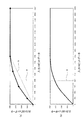
例えば、図4に示すように、G(グリーン)フィルタの感度が、R(レッド)フィルタ、B(ブルー)フィルタの2倍程度の感度を有するRGBフィルタ(図4のa、b、c)を有するCCD20の場合、太陽光のように広い波長帯域を持つ光が同じだけRGBフィルタに入射したときに、R、Bフィルタの各画素出力に対してGフィルタ(図4のcの斜線部分)の画素出力の方が先に飽和レベルAに達してしまう。なお、図3において、fはGフィルタの画素感度特性、gはR、Bフィルタの各画素感度特性であり、Gフィルタの画素感度特性は、R、Bフィルタの各画素感度特性の2倍程度の感度を有している。
For example, as shown in FIG. 4, an RGB filter (a, b, c in FIG. 4) has a sensitivity of the G (green) filter that is about twice that of an R (red) filter and a B (blue) filter. In the case of the
ところで、従来のRGBフィルタを有するCCDなどの固体撮像素子を有するデジタルカメラでは、図4のa、b、cのRGBフィルタのように、感度の高いGフィルタの画素出力に応じた飽和レベルAに合わせてダイナミックレンジの範囲を設定している。即ち、Gフィルタの画素出力が飽和レベルAに達している場合でも、R、Bフィルタの画素出力は飽和レベルAの1/2程度である。 By the way, in a digital camera having a solid-state image sensor such as a CCD having a conventional RGB filter, a saturation level A corresponding to the pixel output of a highly sensitive G filter, such as the RGB filters of a, b, and c in FIG. In addition, the dynamic range is set. That is, even when the pixel output of the G filter reaches the saturation level A, the pixel output of the R and B filters is about ½ of the saturation level A.
これに対して、本発明では、図4のd、eのRGBフィルタのように、Gフィルタの画素出力が飽和レベルAを超えていても、R、Bフィルタの各画素出力が飽和レベルAを超えていない範囲内にあるときに、R、Bフィルタの各画素出力レベルから、R、Bフィルタの各画素感度特性(図4のg)とGフィルタの画素感度特性(図4のf)とに基づいてGフィルタの画素出力レベルを補正(一点鎖線部分)し、この補正した分だけダイナミックレンジを拡大するようにした。 On the other hand, in the present invention, even if the pixel output of the G filter exceeds the saturation level A, as in the RGB filters of d and e in FIG. From within the pixel output levels of the R and B filters, the pixel sensitivity characteristics of the R and B filters (g in FIG. 4) and the pixel sensitivity characteristics of the G filter (f in FIG. 4) Based on this, the pixel output level of the G filter is corrected (one-dot chain line portion), and the dynamic range is expanded by this correction.
前記したように本実施形態では、太陽光のように広い波長帯域を持つ光に対して、Gフィルタの画素感度特性は、R、Bフィルタの各画素感度特性の2倍程度の感度を有している。よって、本実施形態におけるダイナミックレンジの拡大度合の最大値は、ダイナミックレンジの拡大処理動作を行わない通常の静止画撮影モード時に対して2倍程度である。 As described above, in the present embodiment, the pixel sensitivity characteristic of the G filter has a sensitivity about twice that of each pixel sensitivity characteristic of the R and B filters with respect to light having a wide wavelength band such as sunlight. ing. Therefore, the maximum value of the dynamic range expansion degree in this embodiment is about twice that in the normal still image shooting mode in which the dynamic range expansion processing operation is not performed.
なお、本実施形態では、Gフィルタの画素感度特性がR、Bフィルタの各画素感度特性の2倍程度の感度を有し、これに基づいてダイナミックレンジの拡大度合の最大値が2倍としたが、RGBフィルタの各画素感度特性を変化させることにより、ダイナミックレンジの拡大度合の最大値を2倍以上の所定値、あるいは2倍以下の所定値に設定することができる。 In this embodiment, the pixel sensitivity characteristic of the G filter has a sensitivity that is about twice that of the pixel sensitivity characteristics of the R and B filters, and based on this, the maximum value of the degree of expansion of the dynamic range is doubled. However, by changing the pixel sensitivity characteristics of the RGB filter, the maximum value of the degree of expansion of the dynamic range can be set to a predetermined value of 2 times or more, or a predetermined value of 2 times or less.
(Dレンジ拡大補正部50の構成)
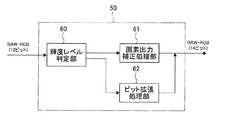
図3に示したYUV変換部36のDレンジ拡大補正部50は、前記したダイナミックレンジを拡大するためのダイナミックレンジ拡大処理機能を有している。Dレンジ拡大補正部50は、図5に示すように、輝度レベル判定部60、画素出力補正処理部61、ビット拡張処理部62を備えている。
(Configuration of D range expansion correction unit 50)
The D range
輝度レベル判定部60は、入力される前記RAW−RGBデータからRGBフィルタを設けた各画素の画素出力を検出するとともに、Gフィルタを設けた画素の画素出力(以下、「Gフィルタの画素出力」という)が飽和領域に達しているか否かを、その周辺のR、Bフィルタを設けた画素の画素出力(以下、「R、Bフィルタの画素出力」という)のそれぞれの出力が、予め設定されているG画素飽和判定閾値以上に達しているか否かによって判定する。そして、輝度レベル判定部60は、感度が一番高いGフィルタの画素出力が飽和領域に達していると判定された場合に、Gフィルタの画素出力の補正を行うための後述する補正係数を算出する。
The luminance
画素出力補正処理部61は、輝度レベル判定部60で算出された補正係数をGフィルタの画素出力に乗算することによって、Gフィルタの画素出力の補正処理を行う。
The pixel output
ビット拡張処理部62は、輝度レベル判定部60で前記したようにGフィルタの画素出力が飽和領域に達していると判断された場合に、R、Bフィルタの画素出力に対して、出力レベルの補正を行うことなく12ビットから14ビットにそれぞれビット拡張のみを行う。なお、ビット拡張処理部62は、輝度レベル判定部60でRGBフィルタの各画素出力が飽和レベルに達していないと判定された場合に、RGBフィルタの各画素出力に対して、出力レベルの補正を行うことなく12ビットから14ビットにそれぞれビット拡張のみを行う。
When the luminance
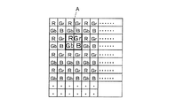
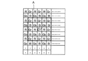
輝度レベル判定部60でGフィルタの画素出力の補正係数を算出する際において、本実施形態では、RGBフィルタを有するCCD20の各画素に対して、図6に示すように、太枠A内の2×2画素(2つのGフィルタの画素、1つずつのR、Bフィルタの画素)を処理単位(最小単位)とする。Gフィルタの画素出力の補正係数(K)、補正処理(予測補間処理)後のGフィルタの画素出力(Ge)、は、それぞれ下記の式(1)、式(2)から算出される。
In calculating the correction coefficient of the pixel output of the G filter by the luminance
K={l×f(Ro)+m×f(Go)+n×f(Bo)}/3 …式(1)
Ge=K×Go …式(2)
ただし、l、m、nはRGBの各フィルタの感度比率から設定される係数、Goは補正処理前のGフィルタの画素出力である。また、f(Ro)、f(Go)、f(Bo)は、下記の数1(式(3)〜式(5))で設定される係数である。
K = {l * f (Ro) + m * f (Go) + n * f (Bo)} / 3 Formula (1)
Ge = K × Go (2)
Here, l, m, and n are coefficients set from the sensitivity ratios of the RGB filters, and Go is the pixel output of the G filter before correction processing. Further, f (Ro), f (Go), and f (Bo) are coefficients set by the following equation 1 (Equation (3) to Equation (5)).

ただし、RoはRフィルタの画素出力、TRはRフィルタの画素出力に対応するG画素飽和判定レベル、Goは補正処理前のGフィルタの画素出力、TGはGフィルタの画素出力の飽和判定レベル、BoはBフィルタの画素出力、TBはBフィルタの画素出力に対応するG画素飽和判定レベルである。 Where Ro is the pixel output of the R filter, TR is the G pixel saturation determination level corresponding to the pixel output of the R filter, Go is the pixel output of the G filter before correction processing, TG is the saturation determination level of the pixel output of the G filter, Bo is a pixel output of the B filter, and TB is a G pixel saturation determination level corresponding to the pixel output of the B filter.
前記式(3)〜式(5)におけるG画素飽和判定レベルTR、TG、TBは、例えば、図7に示したRGBフィルタの各画素出力に対する所定の飽和判定レベルに相当する。なお、図7において、A(TG)はGフィルタの画素出力の飽和レベル(飽和判定レベル)、TRはRフィルタの画素出力の飽和判定レベル、TBはBフィルタの画素出力に対応するG画素飽和判定レベルである。 The G pixel saturation determination levels TR, TG, and TB in the equations (3) to (5) correspond to, for example, predetermined saturation determination levels for the respective pixel outputs of the RGB filter shown in FIG. In FIG. 7, A (TG) is the saturation level (saturation determination level) of the pixel output of the G filter, TR is the saturation determination level of the pixel output of the R filter, and TB is the G pixel saturation corresponding to the pixel output of the B filter. It is a judgment level.
本実施形態にいては、前記したようにGフィルタを設けた画素の感度が、RフィルタおよびBフィルタを設けた画素の感度の2倍としているため、Gフィルタの画素が飽和レベルAに最初に達する。よって、飽和レベルAに達した出力値をGフィルタの画素出力の飽和判定レベルTGとし、RフィルタおよびBフィルタの各画素出力に対応するG画素飽和判定レベルTR、TBは、TGの1/2の値に設定した。なお、TR、TG、TBは、撮像装置(デジタルカメラなど)に用いられるRGBフィルタを有する固体撮像素子(CCDなど)の感度比に依存し、図7に示したような比率に限定されるものではない。 In this embodiment, since the sensitivity of the pixel provided with the G filter is twice the sensitivity of the pixel provided with the R filter and the B filter as described above, the pixel of the G filter first reaches the saturation level A. Reach. Therefore, the output value that has reached the saturation level A is set as the saturation determination level TG of the pixel output of the G filter, and the G pixel saturation determination levels TR and TB corresponding to the pixel outputs of the R filter and the B filter are 1/2 of TG. Was set to the value of Note that TR, TG, and TB depend on the sensitivity ratio of a solid-state imaging device (such as a CCD) having an RGB filter used in an imaging device (such as a digital camera) and are limited to the ratios shown in FIG. is not.
前記式(1)〜式(5)のように、R、G、Bフィルタの各画素出力とG画素飽和判定レベルTR、TG、TBとの比を算出し、これらの算出値にRGBの各フィルタの感度比率から設定される係数を掛けて平均することで、Gフィルタの画素出力を補正する係数を算出し、算出した補正係数(K)をGフィルタの画素出力に掛けることで補正後のGフィルタの画素出力を算出する。そして、この補正係数(K)により前記式(2)から算出された補正後のGフィルタの画素出力(Ge)の値は、処理単位(図6参照)内にある2つのGフィルタの画素出力値として置き換えられる。 As in the above formulas (1) to (5), the ratios of the pixel outputs of the R, G, and B filters and the G pixel saturation determination levels TR, TG, and TB are calculated, and the RGB values are calculated as these calculated values. A coefficient for correcting the pixel output of the G filter is calculated by multiplying the coefficient set from the sensitivity ratio of the filter and averaging, and the corrected correction coefficient (K) is multiplied by the pixel output of the G filter to obtain a corrected result. The pixel output of the G filter is calculated. Then, the value of the pixel output (Ge) of the G filter after correction calculated from the equation (2) by the correction coefficient (K) is the pixel output of the two G filters in the processing unit (see FIG. 6). Replaced as a value.
なお、このGフィルタの画素出力値は12ビットを超えたデータになるため、ここでは一度14ビットのデータに置き換える。よって、R、Bフィルタの各画素出力の最大値はいずれも4095(12ビット)なので、Gフィルタの画素出力の最大値は8190となり、14ビットのデータとして扱うことができる。 Since the pixel output value of the G filter exceeds 12 bits, it is replaced with 14-bit data here. Therefore, since the maximum value of each pixel output of the R and B filters is 4095 (12 bits), the maximum value of the pixel output of the G filter is 8190 and can be handled as 14-bit data.
ところで、輝度レベル判定部60で、Gフィルタの画素出力が飽和領域に達しているか否かを判定処理する際に、欠陥画素をこの判定に用いないようにする必要がある。即ち、Gフィルタを設けた画素に欠陥画素があり、常に飽和領域の値を出力する場合には、同じ処理単位(図6参照)内にあるGフィルタを設けた画素の出力を大きな値に置き換えてしまうため、新たな欠陥画素を生成してしまうことになる。
By the way, when the luminance
また、処理単位(図6参照)内にあるR、Bフィルタを設けた各画素の少なくともいずれか一方の画素に欠陥画素がある場合には、前記式(1)によって算出されるGフィルタの画素出力の補正係数(K)が正しくない値になってしまい、これにより式(2)によって算出される補正処理後のGフィルタの画素出力(Ge)の値も正しくない値になってしまう。 Further, when there is a defective pixel in at least one of the pixels provided with the R and B filters in the processing unit (see FIG. 6), the pixel of the G filter calculated by the above equation (1) The output correction coefficient (K) becomes an incorrect value, and the value of the pixel output (Ge) of the G filter after the correction process calculated by the equation (2) also becomes an incorrect value.
このため、本実施形態では、輝度レベル判定部60がRGBフィルタを設けた各画素の画素出力を検出する際に、常に飽和領域の値が出力されていると判定した場合には処理単位(図6参照)内に欠陥画素があると判断する。そして、このように欠陥画素があると判断した場合には、その処理単位内にある欠陥画素でない画素と、その処理単位の周囲にある欠陥画素と同じ色のフィルタを設けた画素(欠陥画素でない画素)を代わりに用いて、前記したように各画素の画素出力を検出する。
For this reason, in the present embodiment, when the luminance
これにより、輝度レベル判定部60がGフィルタの画素出力が飽和領域に達しているか否かを判定処理する際に、欠陥画素を用いることを防止することができるので、Gフィルタが配置された画素の出力に対して、飽和領域に達していると判定した場合に、前記式(1)〜式(5)により精度の高い補正処理を行うことができる。
Accordingly, when the luminance
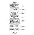
次に、本実施形態における前記したダイナミックレンジ拡大モードでの静止画撮影動作を、図8、図9に示したフローチャートを参照して説明する。最初に、図8に示したフローチャートを参照して、前記RAW−RGBデータ(図3のA)がYUV変換部36のDレンジ拡大補正部50に入力される第1の処理について説明する。次に、図9に示したフローチャートを参照して、前記RAW−RGBデータ(図3のB)がYUV変換部36のDレンジ拡大補正部50側に入力されることなくホワイトバランス制御部52に入力される第2の処理について説明する。
Next, the still image shooting operation in the above-described dynamic range expansion mode in the present embodiment will be described with reference to the flowcharts shown in FIGS. First, the first process in which the RAW-RGB data (A in FIG. 3) is input to the D range
なお、Dレンジ拡大補正部50に入力されるRAW−RGBデータ(図3のA)と、Dレンジ拡大補正部50側に入力されることなくホワイトバランス制御部52に入力されるRAW−RGBデータ(図3のB)は、SDRAM23から読み出される同じRAW−RGBデータである。
RAW-RGB data (A in FIG. 3) input to the D range
(第1の処理:図8のフローチャート)
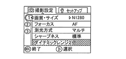
第1の処理では、例えば、被写体の背景の一部に極端に明るい部分がある場合などに、撮影者がメニュー(MENU)ボタン12(図1(C)参照)を押圧操作することにより、例えば、図10に示すような撮影設定画面が液晶モニタ(LCD)9に表示され、この表示画面から「ダイナミックレンジ2倍」の項目を選択することにより、制御部28からYUV変換部36へ制御信号が出力され、ダイナミックレンジを2倍に拡大するダイナミックレンジ拡大モードが実行される。
(First process: flowchart of FIG. 8)
In the first process, for example, when the photographer has an extremely bright part of the background of the subject, the photographer presses the menu (MENU) button 12 (see FIG. 1C), for example, A shooting setting screen as shown in FIG. 10 is displayed on the liquid crystal monitor (LCD) 9, and the control signal is sent from the
そして、前記したモニタリング動作から撮影者がレリーズボタン2を押圧(半押しから全押し)することにより、信号処理部22のカメラI/F34は、撮影レンズ系5、CCD20、AFE部21を介してRAW−RGBデータを取り込む(ステップS1)。
Then, when the photographer presses the release button 2 (half press to full press) from the monitoring operation described above, the camera I /
そして、カメラI/F34は、取り込んだRAW−RGBデータより、AE(自動露出)評価値、AF(自動合焦)評価値、AWB(オートホワイトバランス)評価値を算出し、制御部28は、算出した前記AE評価値に基づいてAE処理を行い、撮影時の露出を決定する(ステップS2)。更に、制御部28は、算出した前記AF評価値に基づいてAF処理を行い、撮影レンズ系5のフォーカスレンズを合焦位置に移動させ、合焦させる(ステップS3)。
Then, the camera I /
そして、ステップS2で決定した露出条件に基づいて撮影(記録)用の露光を行うことにより(ステップS4)、被写体像がCCD20の各画素の受光面上に結像する。そして、CCD20から出力される被写体像に応じた電気信号(アナログRGB画像信号)は、CDS31、AGC32を介してA/D変換部33に出力され、A/D変換部33により12ビット(bit)のRAW−RGBデータに変換される。このRAW−RGBデータは、信号処理部22のカメラI/F34に取り込まれてメモリコントローラ35を介してSDRAM23に保存される。ここまでの処理は、前記した通常の静止画撮影動作と同様である。
Then, by performing exposure for photographing (recording) based on the exposure condition determined in step S2 (step S4), a subject image is formed on the light receiving surface of each pixel of the
そして、SDRAM23から読み出したRAW−RGBデータ(図3のA)をYUV変換部36のDレンジ拡大補正部50に入力し、Dレンジ拡大補正部50の輝度レベル判定部60により、前記したようにRGBフィルタを設けた各画素の画素出力を検出し(ステップS5)、予め設定している飽和判定値に達しているか否かによって画素出力が飽和しているか否かを判定する(ステップS6)。飽和領域に達している画素出力があると判定した場合には(ステップS6;YES)、飽和領域以上に達している画素出力が一番感度の高いGフィルタの画素出力のみであるか否かを判定する(ステップS7)。
Then, the RAW-RGB data (A in FIG. 3) read from the
ステップS7で、飽和領域に達している画素出力がGフィルタの画素出力のみであると判定した場合(ステップS7;YES)、輝度レベル判定部60は、前記式(1)、式(3)〜式(5)よりGフィルタの画素出力の補正を行うための補正係数を算出する(ステップS8)。そして、画素出力補正処理部61は、前記式(2)のようにステップS7で算出された補正係数をGフィルタの画素出力に乗算して、Gフィルタの画素出力を補正処理する(ステップS9)。
When it is determined in step S7 that the pixel output reaching the saturation region is only the pixel output of the G filter (step S7; YES), the luminance
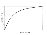
そして、ビット圧縮変換部51は、Dレンジ拡大補正部(輝度レベル判定部60、画素出力補正処理部61)50で14ビットに拡張されたGフィルタの画素出力データを、例えば、図11(a)に示すような変換特性(3箇所の節点を指定し、それらの間を直線で近似する4区間の折れ線近似特性)によって、12ビットデータにビット圧縮する(ステップS10)。なお、図11(a)において、aは12ビットの範囲であり、bは最大値8190のデータを1/2倍する場合における単純な線形変換特性(一点鎖線部分)である。図11(a)に示す変換特性では、Gフィルタの画素出力の最大値は8190なので、8190が4095になるように圧縮する。そして、Gフィルタの画素出力の圧縮倍率に合わせて、R、Bフィルタの画素出力の値も圧縮する。
Then, the bit
そして、ビット圧縮変換部51で14ビットから12ビットに圧縮変換されたRGBフィルタの画素出力データは、ホワイトバランス制御部52に入力され、ホワイトバランス(AWB)処理される(ステップS11)。詳細には、ホワイトバランス制御部52は、入力されるRAW−RGBデータをそれぞれ増幅する。この際、制御部28は、カメラI/F34で算出された前記AWB評価値に基づいてホワイトバランスを合わせるための補正値を算出し、算出した補正値をホワイトバランス制御部52に出力する。ホワイトバランス制御部52は、入力される前記補正値に基づいてホワイトバランスを合わせる。
The RGB filter pixel output data compressed and converted from 14 bits to 12 bits by the bit
そして、ホワイトバランス制御部52からホワイトバランスが合わされたRGBフィルタの画素出力データ(12ビット)は、同時化部53に入力される。同時化部53は、ベイヤ配列等の1画素に1色のデータしか持っていないRAWデータに対して補間演算処理を行い、1画素に対してRGBの全てのデータを生成する。そして、同時化部53で生成されたRGBの全てのデータ(12ビット)は、トーンカーブ変換部54に入力される。トーンカーブ変換部54は、例えば、図12に示すような変換テーブルによって12ビットのRGBのデータを8ビットのRGBのデータに変換するγ変換を行って、8ビットのRGB値を生成し、RGB−YUV変換部55に出力する。
Then, the pixel output data (12 bits) of the RGB filter with the white balance adjusted from the white
RGB−YUV変換部55は、入力されるRGBデータ(8ビット)をマトリックス演算によりYUVデータ(以下、「第1YUVデータ」という)に変換する(ステップS12)。そして、画像サイズコンバータ部56は、この第1YUVデータに対して所望の画像サイズに縮小または拡大を行い、エッジエンハンス部57および輝度ヒストグラム生成部58に出力する。
The RGB-
エッジエンハンス部57は、入力される第1YUVデータに対して画像に合わせたエッジ強調等の処理を行い、この第1YUVデータを、メモリコントローラ35を介してSDRAM23に保存する(ステップS13)。輝度ヒストグラム生成部58は、入力される第1YUVデータにより輝度ヒストグラムを生成する。
The
(第2の処理:図9のフローチャート)
第2の処理では、前記第1の処理(図8のステップS1〜S4)で得られた前記RAW−RGBデータをSDRAM23から読み出し(ステップS21)、このRAW−RGBデータ(図3のB)をDレンジ拡大補正部50、ビット圧縮変換部51に通すことなくホワイトバランス制御部52に入力し、前記第1の処理時と同様にホワイトバランス(AWB)処理を行う(ステップS22)。なお、このRAW−RGBデータ(図3のB)は、前記第1の処理で述べたように、Gフィルタの画素出力が飽和領域に達している。
(Second process: flowchart of FIG. 9)
In the second process, the RAW-RGB data obtained in the first process (steps S1 to S4 in FIG. 8) is read from the SDRAM 23 (step S21), and the RAW-RGB data (B in FIG. 3) is read. The signal is input to the white
そして、ホワイトバランス制御部52からホワイトバランスが合わされたRGBフィルタの画素出力データ(12ビット)は、同時化部53に入力される。同時化部53は、ベイヤ配列等の1画素に1色のデータしか持っていないRAWデータに対して補間演算処理を行い、1画素に対してRGBの全てのデータを生成する。そして、同時化部53で生成されたRGBの全てのデータ(12ビット)は、トーンカーブ変換部54に入力される。トーンカーブ変換部54は、例えば、図12に示したような変換テーブルによって12ビットのRGBのデータを8ビットのRGBのデータに変換するγ変換を行って、8ビットのRGB値を生成し、RGB−YUV変換部55に出力する。
Then, the pixel output data (12 bits) of the RGB filter with the white balance adjusted from the white
RGB−YUV変換部55は、入力されるRGBデータ(8ビット)をマトリックス演算によりYUVデータ(以下、「第2YUVデータ」という)に変換する(ステップS23)。そして、画像サイズコンバータ部56は、この第2YUVデータに対して所望の画像サイズに縮小または拡大を行い、エッジエンハンス部57および輝度ヒストグラム生成部58に出力する。
The RGB-
エッジエンハンス部57は、入力される第2YUVデータに対して画像に合わせたエッジ強調等の処理を行い、この第2YUVデータを、メモリコントローラ35を介してSDRAM23に保存する(ステップS24)。
The
そして、YUV合成部37は、SDRAM23から読み出した前記第1YUVデータからYデータ(輝度データ)のみを取り出すとともに、SDRAM23から読み出した前記第2YUVデータからUVデータ(色差データ)のみを取り出して、1つのYUVデータ(以下、「第3YUVデータ」という)を合成する(ステップS25)。この合成処理された第3YUVデータは、メモリコントローラ35を介してSDRAM23に保存される。
The
そして、この第3YUVデータはSDRAM23から読み出されて、リサイズ処理部38で記録画素数に対応するサイズに変換され、データ圧縮部40でJPEG形式等の画像データへと圧縮される(ステップS26)。圧縮されたJPEG形式等の画像データは、SDRAM23に書き戻された後にメモリコントローラ35を介してSDRAM23から読み出され、メディアI/F41を介してメモリカード14に記録される(ステップS27)。
The third YUV data is read from the
ところで、前記した第1の処理(図9のフローチャート)のステップS10では、14ビットに拡張されたGフィルタの画素出力データを12ビットデータにビット圧縮する際に、最大値が8190に拡張されたGフィルタの画素出力を最大値が4095に圧縮する際の一例として、図11(a)に示したような3つの節点を有する変換特性を用いた。これによって、単純な節点のない線形変換特性(図11(a)のb)では得られない以下のような2つの効果が得られる。 By the way, in step S10 of the first process described above (the flowchart of FIG. 9), when the pixel output data of the G filter expanded to 14 bits is bit-compressed to 12-bit data, the maximum value is expanded to 8190. As an example of compressing the pixel output of the G filter to a maximum value of 4095, a conversion characteristic having three nodes as shown in FIG. As a result, the following two effects that cannot be obtained with a linear conversion characteristic without a simple node (b in FIG. 11A) are obtained.
第1の効果としては、データの信頼性が高いデータにより多くのビット数を割り当てることができる。即ち、飽和領域以上に達しているGフィルタの画素出力に対して補正処理する場合、前記したようにGフィルタの画素出力の飽和領域付近の規定値以上の値になった範囲について補正を行い、この規定値以下の範囲では補正は行われない。よって、補正を行う範囲と行わない範囲とでは、データの精度が異なっている。 As a first effect, a larger number of bits can be assigned to data with high data reliability. That is, when performing correction processing on the pixel output of the G filter that has reached the saturation region or more, as described above, correction is performed for the range in which the value of the pixel output of the G filter is equal to or greater than the specified value near the saturation region, Correction is not performed in the range below this specified value. Therefore, the accuracy of data differs between the range where correction is performed and the range where correction is not performed.
即ち、例えば前記式(1)〜式(5)によって飽和しているGフィルタの画素出力値を補正する場合、主被写体の色によっては、補正を行う範囲においては被写体の輝度レベルが正確に再現できていない場合がある。これに対して補正を行っていない範囲は、RGBフィルタを有するCCD20から出力される実際のデータ(アナログRGB画像信号)をA/D変換したデータであるので、このデータの信頼性は高いものとなる。
That is, for example, when correcting the pixel output value of the saturated G filter according to the equations (1) to (5), the luminance level of the subject is accurately reproduced in the correction range depending on the color of the main subject. It may not be possible. On the other hand, the range where correction is not performed is data obtained by A / D conversion of actual data (analog RGB image signal) output from the
即ち、図11(a)に示した本実施形態における変換特性では、例えば、入力14ビットデータが1024ときに出力12ビットデータは1024になっており、元のデータがそのまま使われている。これに対し、例えば、入力14ビットデータが3072ときに出力12ビットデータは2560になっており、この範囲では補正前のビット割付よりも少ない割付となることによって、多少のビット誤差が発生する。 That is, in the conversion characteristics in this embodiment shown in FIG. 11A, for example, when the input 14-bit data is 1024, the output 12-bit data is 1024, and the original data is used as it is. On the other hand, for example, when the input 14-bit data is 3072, the output 12-bit data is 2560, and in this range, the bit allocation is smaller than the bit allocation before correction, so that some bit error occurs.
このように、単純な節点のない線形変換を行う特性((図11(a)のb)ではなく、本実施形態のように3つの節点を有する変換特性を採用することにより、ビット割付をだんだんと少なくしていくことができるので、データの信頼性が高いデータにより多くのビット数を割り当てることができる。 In this way, bit allocation is gradually increased by adopting a conversion characteristic having three nodes as in this embodiment instead of a characteristic for performing linear conversion without simple nodes (b in FIG. 11A). Therefore, it is possible to allocate more bits to data with high data reliability.
そして、第2の効果としては、低・中輝度における階調を正確に保存することができる。即ち、単純な線形変換特性(図11(a)のb)でビット圧縮を行った場合、低輝度側の補正が行われていない範囲では、ビット割付が1/4になってしまう。このため、階調感のない画像になってしまう。これに対し、図11(a)に示したような本実施形態における変換特性でビット圧縮を行った場合には、飽和領域以下で低輝度レベルにおける画素出力に対応したデータに対しては、ビット圧縮変換部51でビット圧縮する前とビット圧縮した後で略同じ値となるような圧縮率を用いることにより、低輝度レベルにおける階調性を良好に保持することができる。
As a second effect, gradations at low and medium luminance can be accurately stored. That is, when bit compression is performed with a simple linear conversion characteristic (b in FIG. 11A), the bit allocation becomes 1/4 in a range where correction on the low luminance side is not performed. For this reason, the image has no tone. On the other hand, when bit compression is performed with the conversion characteristics in the present embodiment as shown in FIG. 11A, the bit corresponding to the pixel output at the low luminance level below the saturation region is a bit. By using a compression ratio that gives substantially the same value before bit compression by the
なお、本実施形態では、拡張したGフィルタの画素出力の14ビットデータを12ビットに縮小するときに、図11(a)のように3つの節点を指定し、それらの間を直線で近似する4区間の折れ線近似特性(変換特性)でビット圧縮を行う構成であったが、この区間数は特に限定されるものではない。例えば、1つの節点を指定する2区間の折れ線近似特性としてもよいが、節点付近でビット割付が大きく変わることにより、前記した2つの効果が小さくなる。よって、3区間以上の区間数を有する折れ線近似特性(変換特性)が好ましい。 In this embodiment, when the 14-bit data of the pixel output of the expanded G filter is reduced to 12 bits, three nodes are designated as shown in FIG. 11A and approximated by a straight line between them. Although the bit compression is performed with the broken line approximation characteristic (conversion characteristic) of four sections, the number of sections is not particularly limited. For example, it may be a polygonal line approximate characteristic of two sections designating one node, but the above-mentioned two effects are reduced by changing the bit allocation in the vicinity of the node. Therefore, a broken line approximation characteristic (conversion characteristic) having three or more sections is preferable.
また、拡張したGフィルタの画素出力の14ビットデータを12ビットに圧縮する変換特性を、図11(b)に示すように、複数の節点を有していない曲線による変換特性としてもよい。即ち、図11(a)の4区間を有する変換特性に対して、区間数を8192にしたものがこの曲線による変換特性となる。なお、図11(b)において、aは12ビットの範囲である。 Further, the conversion characteristic for compressing the 14-bit data of the expanded G filter pixel output to 12 bits may be a conversion characteristic by a curve having no plurality of nodes as shown in FIG. That is, in contrast to the conversion characteristic having four sections in FIG. 11A, a conversion characteristic with this curve is obtained by setting the number of sections to 8192. In FIG. 11B, a is a 12-bit range.
更に、入力14ビットデータの0〜8192に対して、12ビットに圧縮変換後の数値データを持ったルックアップテーブルを設けておくことにより、この曲線による変換特性で、拡張したGフィルタの画素出力の14ビットデータを良好に12ビットに圧縮することができる。 Further, by providing a lookup table having numerical data after compression conversion to 12 bits for 0 to 8192 of input 14-bit data, the pixel output of the expanded G filter with the conversion characteristics by this curve is provided. The 14-bit data can be successfully compressed to 12 bits.
上記したように、本実施形態のダイナミックレンジ拡大モードによる静止画撮影動作を行うことにより、感度の高いGフィルタの画素出力が飽和領域に達しているような場合においても、Gフィルタよりも感度の低いR、Bフィルタの画素出力に基づいて、飽和しているGフィルタの画素出力を補正処理することにより、図4に示したように、Gフィルタ(図4のd、e)の画素出力の補正した拡張領域(図4のd、eのGフィルタの画素出力の一点鎖線で示した部分)に基づいて、1回の撮影でダイナミックレンジを2倍に拡大することが可能となる。 As described above, by performing the still image shooting operation in the dynamic range expansion mode of the present embodiment, even when the pixel output of the G filter with high sensitivity reaches the saturation region, the sensitivity is higher than that of the G filter. By correcting the pixel output of the saturated G filter based on the pixel output of the low R and B filters, the pixel output of the G filter (d and e in FIG. 4) is corrected as shown in FIG. Based on the corrected extended region (the portion indicated by the alternate long and short dash line of the pixel output of the G filter of d and e in FIG. 4), the dynamic range can be doubled by one shooting.
よって、撮影画像内の背景等に高輝度部分がある場合でも、白とびの発生を防止して良好な階調性を得ることが可能となる。 Therefore, even when there is a high-luminance portion in the background or the like in the captured image, it is possible to prevent the occurrence of overexposure and obtain good gradation.
更に、本実施形態では、SDRAM23から一つのRAW−RGBデータを読み出して、前記第1の処理により画素出力補正処理部61で補正された画素出力から生成される第1YUVデータと、前記第2の処理により画素出力補正処理部61で補正処理を行うことなく飽和領域に達している画素出力から生成される第2YUVデータをYUV合成部37に取り込み、YUV合成部37で第1YUVデータから取り出したYデータ(輝度データ)と、第2YUVデータから取り出したUVデータ(色差データ)とを合成して、第3YUVデータを生成する。
Further, in the present embodiment, one RAW-RGB data is read from the
これにより、画素出力補正処理部61により補正された画素出力から生成される第1YUVデータのYデータ(輝度データ)についてのみダイナミックレンジの拡大を行い、色は元のUVデータ(色差データ)を用いることで、ダイナミックレンジ拡大時における色相のずれを防止して正確な色の再現を行うことができる。
Thereby, the dynamic range is expanded only for the Y data (luminance data) of the first YUV data generated from the pixel output corrected by the pixel output
例えば、Dレンジ拡大補正部50により、飽和していると判定したGフィルタの画素出力の補正処理を前記式(1)〜式(5)を用いて行って、ダイナミックレンジの拡大処理を行ったときに、例えば、主被写体がマゼンタ色の場合には、R、Bフィルタの画素出力が大きくなる。このため、これに伴ってGフィルタの画素出力は本来よりも大きな値に算出されてしまい、その結果、正確な色の再現ができない場合がある。
For example, the D range
このような状況の場合でも、前記した本実施形態のダイナミックレンジ拡大モードによる静止画撮影動作を行うことにより、第1YUVデータのYデータ(輝度データ)についてのみダイナミックレンジの拡大を行い、色は元のUVデータ(色差データ)を用いることで、ダイナミックレンジ拡大時における色相のずれを防止して正確な色の再現を行うことができる。 Even in such a situation, the dynamic range is expanded only for the Y data (luminance data) of the first YUV data by performing the still image shooting operation in the dynamic range expansion mode of the present embodiment, and the color is the original. By using this UV data (color difference data), it is possible to prevent hue shift when expanding the dynamic range and to accurately reproduce colors.
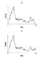
図13(a)は、Gフィルタの画素出力が飽和領域を超えたときに、前記した本実施形態におけるダイナミックレンジの拡大処理を行った場合の、輝度ヒストグラム生成部58で生成されたヒストグラムの一例である。このヒストグラムから明らかなように、前記した本実施形態におけるダイナミックレンジの拡大処理を行った場合には、最大輝度部分(255)まで画素を残して高輝度部分に対して適切な階調を確保することができ、白飛びの発生を防止することができる。
FIG. 13A shows an example of a histogram generated by the luminance
これに対し、図13(b)は、Gフィルタの画素出力が飽和領域であるときに、前記した本実施形態におけるダイナミックレンジの拡大処理を行わなかった場合の、輝度ヒストグラム生成部58で生成されたヒストグラムの一例である。このヒストグラムから明らかなように、本実施形態におけるダイナミックレンジの拡大処理を行わなかった場合には、最大輝度部分(255)に多くの画素数が存在し、白とびが発生している。
On the other hand, FIG. 13B is generated by the luminance
なお、前記した実施形態1の説明および図4において、飽和判定値である図4の飽和レベルAと、補正後の12ビットの最大値である4095とが一致しているように説明したが、これに限定するものではない。例えば、出力が完全に飽和する付近の高輝度部において、出力の直線性(リニアリティー)が良くないRGBフィルタを有するCCDでは、例えば完全に飽和する4095よりも小さい値である4032を飽和判定値(図4の飽和レベルA)とおいて、その値を超えた画素出力を補正処理の対象としてもよい。この場合においても、Gフィルタの画素出力が飽和判定値である4032を超えていると判定するための飽和判定閾値(ここでは、例えば4032/2=2016)に対して、R、Bフィルタの画素出力が超えているか否かによってGフィルタの画素出力の飽和を判定する。
In the description of
また、デジタルカメラのシステム構成によっては、高輝度被写体でも12ビットの最大値である4095にならないものもある。その場合も同様に飽和判定値を4095よりも低い値に設定するとよい。 Also, depending on the system configuration of the digital camera, even a high-luminance subject may not reach 4095, which is the maximum value of 12 bits. In that case as well, the saturation determination value may be set to a value lower than 4095.
このように、4095未満を飽和領域としたときでも、その特性に合わせて図12に示した変換カーブを切り替えることで、ビット圧縮変換部51の出力を4095にすることができ、後段の処理を変えることなくダイナミックレンジの拡大が可能となる。
As described above, even when the saturation region is less than 4095, the output of the bit
なお、本実施形態では、前記したようにGフィルタの画素感度特性が、R、Bフィルタの各画素感度特性の2倍程度の感度を有していることを前提としているため、極端に赤い光源下や青い光源下では、Gフィルタの画素感度よりもR、Bフィルタの画素感度の方が飽和してしまう場合がある。このような状況下で前記したダイナミックレンジの拡大処理を行うと正確な階調および色再現が得られないので、このような場合には撮影者の判断により、前記したダイナミックレンジの拡大処理を行わないようにする。 In the present embodiment, as described above, it is assumed that the pixel sensitivity characteristics of the G filter have a sensitivity that is about twice as high as the pixel sensitivity characteristics of the R and B filters. Under the blue light source or the blue light source, the pixel sensitivity of the R and B filters may be saturated rather than the pixel sensitivity of the G filter. If the dynamic range expansion process described above is performed under such circumstances, accurate gradation and color reproduction cannot be obtained. In such a case, the dynamic range expansion process described above is performed at the discretion of the photographer. Do not.
また、本実施形態では、図3に示したように、Dレンジ拡大補正部50から出力される14ビットのRAW−RGBデータをビット圧縮変換部51で12ビットに圧縮処理し、ホワイトバランス制御部52、同時化部53においては12ビットのデータ処理を行う構成であったが、これ以外にも、同時化部53の後にビット圧縮変換部51を設けて、同時化部53から出力される14ビットのデータを12ビットのデータに圧縮処理する構成でもよい。
In the present embodiment, as shown in FIG. 3, the 14-bit RAW-RGB data output from the D range
〈実施形態2〉
前記実施形態1では図6に示したように、RGBフィルタを有するCCD20に対して、2×2画素を処理単位(最小単位)としていたが、本実施形態では、図14に示すように、太枠A内の5画素(中央部に1つのGフィルタの画素(Gb)、図の上下方向に2つのR(R1,R2)フィルタの画素、図の左右方向に2つのB(B1,B2)フィルタの画素)を処理単位(最小単位)とし、処理単位を前記実施形態1の場合よりも広い範囲とした例である。なお、デジタルカメラの構成、モニタリング動作、静止画撮影動作、およびダイナミックレンジの拡大処理動作は、前記実施形態1と同様である。
<
In the first embodiment, as shown in FIG. 6, 2 × 2 pixels are used as the processing unit (minimum unit) for the
本実施形態では、補正係数算出部60は、処理単位(図14参照)内の1つのGフィルタの画素の周囲にある2つのR1、R2フィルタの画素出力の平均値、および2つのB1、B2フィルタの画素出力の平均値を算出し、算出した各平均値をこの処理単位内のR、Bフィルタの各画素出力の値とする。
In the present embodiment, the correction
図14に示した太枠Aの処理単位内にあるGフィルタの画素出力が飽和領域に達している場合、Gフィルタの感度は、前記したようにR、Bフィルタの感度の約2倍であるため、Gフィルタの画素出力の補正係数(K)、補正後のGフィルタの画素出力(Ge)は、下記の式(6)、式(7)から算出される。本実施形態では、 When the pixel output of the G filter in the processing unit of the thick frame A shown in FIG. 14 reaches the saturation region, the sensitivity of the G filter is about twice the sensitivity of the R and B filters as described above. Therefore, the correction coefficient (K) of the G filter pixel output and the corrected pixel output (Ge) of the G filter are calculated from the following equations (6) and (7). In this embodiment,
K={l×f(Ra)+m×f(Ga)+n×f(Ba)}/3 …式(6)
Ge=K×Ga …式(7)
ただし、l、m、nはRGBの各フィルタの比率から設定される係数、Gaは補正前のGフィルタの画素出力である。また、f(Ra)、f(Ga)、f(Ba)は、下記の数2(式(8)〜式(10))で設定される係数である。
K = {l * f (Ra) + m * f (Ga) + n * f (Ba)} / 3 ... Formula (6)
Ge = K × Ga (7)
Here, l, m, and n are coefficients set from the ratios of the RGB filters, and Ga is the pixel output of the G filter before correction. Further, f (Ra), f (Ga), and f (Ba) are coefficients set by the following formula 2 (Expression (8) to Expression (10)).
ただし、Raは前記処理単位(図14参照)内でのRフィルタの画素出力の平均値、TRはRフィルタの画素出力に対応するG画素飽和判定レベル、Gaは前記処理単位(図14参照)内でのGフィルタの画素出力、TGはGフィルタの画素出力の飽和判定レベル、Baは前記処理単位(図14参照)内でのBフィルタの画素出力の平均値、TBはBフィルタの画素出力に対応するG画素飽和判定レベルである。 However, Ra is an average value of the pixel output of the R filter in the processing unit (see FIG. 14), TR is a G pixel saturation determination level corresponding to the pixel output of the R filter, and Ga is the processing unit (see FIG. 14). G filter pixel output, TG is the saturation determination level of the G filter pixel output, Ba is the average value of the B filter pixel output in the processing unit (see FIG. 14), and TB is the B filter pixel output. G pixel saturation determination level corresponding to.
なお、前記TR、TG、TBは、前記式(3)〜式(5)と同様である。また、前記係数l、m、nは、R、G、Bフィルタの各画素出力の感度比が実施形態1と同様であれば、係数l、nがそれぞれ3/2、mが0となる。 The TR, TG, and TB are the same as those in the equations (3) to (5). The coefficients l, m, and n are 3/2 and m are 0, respectively, if the sensitivity ratio of the pixel outputs of the R, G, and B filters is the same as in the first embodiment.
そして、図6に示したDレンジ拡大補正部50の画素出力補正処理部61は、前記式(7)より算出されたGフィルタの画素出力値を、前記処理単位(図14参照)内にあるGフィルタの画素出力値として置き換え、以下、前記実施形態1と同様の処理を行う。
Then, the pixel output
このように、処理単位を広くすることで、処理単位内の他のR1,R2フィルタの画素、B1,B2フィルタの画素が持っている感度差による影響を緩和することができ、飽和領域以上に達しているGフィルタの画素出力に対して、より正確な補正を行うことが可能となる。 In this way, by widening the processing unit, it is possible to alleviate the influence due to the sensitivity difference of the other R1, R2 filter pixels and B1, B2 filter pixels in the processing unit. It is possible to perform more accurate correction on the pixel output of the G filter that has reached.
〈実施形態3〉
本実施形態では、図15に示すように、RGBフィルタを有するCCD20に対して、太枠A内の水平方向5画素、垂直方向5画素の5×5画素(13個のGフィルタの画素(Gr、Gb)、6個ずつのR、Bフィルタ)を処理単位とした例である。なお、デジタルカメラの構成、モニタリング動作、静止画撮影動作、およびダイナミックレンジの拡大処理動作は、前記実施形態1と同様である。
<
In this embodiment, as shown in FIG. 15, for a
処理単位を前記実施形態1、2の場合よりも広くすると、広い範囲の輝度情報に基づいて処理することになるため、ローパスフィルタをかけたことと等価になってしまう。そのため、輝度変化のエッジ部分がなまってしまう。そこで、本実施形態では、広くした処理単位の大きさを、例えば、前記AF評価値を利用して部分的に変更するものとする。 If the processing unit is wider than those in the first and second embodiments, processing is performed based on a wide range of luminance information, which is equivalent to applying a low-pass filter. Therefore, the edge portion of the luminance change is lost. Therefore, in the present embodiment, the size of the widened processing unit is partially changed using, for example, the AF evaluation value.
即ち、図2に示した信号処理部22のカメラI/F34では、前記したようにAFを行うためのAF評価値を算出している。これは、ハイパスフィルタ(HPF)の出力であり、撮影画像の画面内に輝度の変化がある部分では大きな値が出力される。そして、制御部28は、静止画撮影時のAF評価値を読み出し、画面内の輝度変化がある部分とない部分を判別する。そして、制御部28は、この判別データを基にDレンジ拡大補正部50に対して、輝度変化がある部分には処理単位が狭くなるような設定(例えば、前記実施形態1、2における処理単位の設定)を行い、輝度変化がない部分には、図15に示したように処理単位が広い範囲になるように設定を行う。
That is, the camera I /
このように、処理単位を更に広くした場合でも、輝度変化がある部分には処理単位が狭くなるような設定を行うことで、解像度を落とすことなく、飽和領域に達しているGフィルタの画素出力に対して、正確な補正を行うことが可能となる。 As described above, even when the processing unit is further widened, the pixel output of the G filter that has reached the saturation region without reducing the resolution can be obtained by performing the setting so that the processing unit is narrowed in the portion where the luminance changes. Therefore, accurate correction can be performed.
なお、前記した各実施形態では、色分解フィルタとしてRGBの3原色系フィルタを配置した構成であったが、色分解フィルタとして補色系フィルタを配置した構成においても、同様に本発明を適用することができる。 In each of the embodiments described above, the RGB three primary color filters are arranged as the color separation filters. However, the present invention is similarly applied to a configuration in which the complementary color filters are arranged as the color separation filters. Can do.
1 デジタルカメラ(撮像装置)
5 撮影レンズ系(光学系)
6 鏡胴ユニット
9 液晶モニタ
12 メニューボタン(動作選択手段)
20 CCD(撮像素子)
21 アナログフロントエンド部
22 信号処理部
23 SDRAM
28 制御部
34 カメラインターフェース
35 メモリコントローラ
36 YUV変換部
37 YUV合成部(YUV合成手段)
50 Dレンジ拡大補正部
51 ビット圧縮変換部(ビット圧縮変換手段)
60 輝度レベル判定部(周辺画素飽和判定手段)
61 画素出力補正処理部(飽和画素出力補正処理手段)
62 ビット拡張処理部
1 Digital camera (imaging device)
5 Shooting lens system (optical system)
6
20 CCD (imaging device)
21
28
50 D range
60 Luminance level determination unit (peripheral pixel saturation determination means)
61 Pixel output correction processing unit (saturated pixel output correction processing means)
62-bit extension processing section
Claims (12)
前記各画素からの出力を検出するとともに、検出した画素出力に基づいて周辺のある特定色のフィルタが配置された画素からの出力が、入出力特性が線形でなくなる飽和領域に達しているか否かを判定する周辺画素飽和判定手段と、
前記周辺画素飽和判定手段により、前記特定色のフィルタが配置された画素からの出力が前記飽和領域に達していると判定した場合に、その周囲の前記特定色以外のフィルタが配置された画素からの出力に基づいて、前記特定色のフィルタが配置された画素からの出力を補正する飽和画素出力補正処理手段と、
前記飽和画素出力補正処理手段により前記補正処理された画素出力から生成される第1YUVデータと、前記飽和画素出力補正処理手段で前記補正処理を行うことなく前記飽和領域に達している画素出力から生成される第2YUVデータとを取り込み、前記第1YUVデータから取り出した輝度データと、前記第2YUVデータから取り出した色差データとを合成した第3YUVデータを生成するYUV合成手段と、を有することを特徴とする撮像装置。 An image sensor in which a subject image incident through an optical system is received by a light receiving surface having a plurality of pixels and converted into an electrical signal, and a plurality of color separation filters are disposed on the front side of each pixel;
Whether the output from each pixel detects the output from the pixel, and whether the output from the pixel in which a filter of a specific color is arranged based on the detected pixel output reaches a saturation region where the input / output characteristics are not linear Peripheral pixel saturation determination means for determining
When it is determined by the peripheral pixel saturation determination means that the output from the pixel in which the filter of the specific color is arranged has reached the saturation region, from the pixel in which a filter other than the specific color in the vicinity is arranged Saturated pixel output correction processing means for correcting the output from the pixel in which the filter of the specific color is arranged based on the output of
Generated from the first YUV data generated from the pixel output corrected by the saturated pixel output correction processing means and the pixel output reaching the saturation region without performing the correction processing by the saturated pixel output correction processing means YUV combining means for generating third YUV data obtained by combining the luminance data extracted from the first YUV data and the color difference data extracted from the second YUV data. An imaging device.
前記ビット圧縮変換手段は、前記飽和領域以上における画素出力に対応したデータに対する圧縮率よりも、前記飽和領域以下における画素出力に対応したデータに対する圧縮率を小さくして圧縮することを特徴とする請求項1乃至3のいずれか一項に記載の撮像装置。 From the first number of bits that can represent the saturated region of the pixel output that is output from the saturated pixel output correction processing means when the output of the pixel in which the filter of the specific color has reached the saturated region Bit compression conversion means for compressing the pixel output data once expanded to the second number of bits that can be expressed beyond the saturation region of the pixel output to the first number of bits again,
The bit compression conversion means compresses data by reducing a compression rate for data corresponding to a pixel output in the saturation region or lower than a compression rate for data corresponding to a pixel output in the saturation region or higher. Item 4. The imaging device according to any one of Items 1 to 3.
前記各画素からの出力を検出するとともに、検出した画素出力に基づいて周辺のある特定色のフィルタが配置された画素からの出力が、入出力特性が線形でなくなる飽和領域に達しているか否かを判定する周辺画素飽和判定処理ステップと、
前記周辺画素飽和判定処理ステップにより、特定色のフィルタが配置された画素からの出力が前記飽和領域に達していると判定した場合に、その周囲の前記特定色以外のフィルタが配置された画素からの出力に基づいて、前記特定色のフィルタが配置された画素からの出力を補正する飽和画素出力補正処理ステップと、
前記飽和画素出力補正処理ステップにより前記補正処理された画素出力から生成される第1YUVデータと、前記飽和画素出力補正処理ステップで前記補正処理を行うことなく前記飽和領域に達している画素出力から生成される第2YUVデータとを取り込み、前記第1YUVデータから取り出した輝度データと、前記第2YUVデータから取り出した色差データとを合成した第3YUVデータを生成するYUV合成処理ステップと、を含むことを特徴とする撮像方法。 An imaging device including an imaging device in which a subject image incident through an optical system is received by a light receiving surface having a plurality of pixels and converted into an electrical signal, and a plurality of color separation filters are arranged on the front side of each pixel. In the imaging method of the apparatus,
Whether the output from each pixel detects the output from the pixel, and whether the output from the pixel in which a filter of a specific color is arranged based on the detected pixel output reaches a saturation region where the input / output characteristics are not linear Surrounding pixel saturation determination processing step for determining
When it is determined in the peripheral pixel saturation determination processing step that the output from the pixel in which the filter of the specific color is arranged has reached the saturation region, from the pixel in which the filter other than the specific color in the vicinity is arranged A saturated pixel output correction processing step for correcting the output from the pixel in which the filter of the specific color is arranged based on the output of
Generated from the first YUV data generated from the pixel output corrected by the saturated pixel output correction processing step and the pixel output reaching the saturation region without performing the correction processing in the saturated pixel output correction processing step YUV synthesis processing step of generating third YUV data by taking in the second YUV data to be generated and synthesizing the luminance data extracted from the first YUV data and the color difference data extracted from the second YUV data. An imaging method.
前記ビット圧縮変換処理ステップは、前記飽和領域以上における画素出力に対応したデータに対する圧縮率よりも、前記飽和領域以下における画素出力に対応したデータに対する圧縮率を小さくして圧縮することを特徴とする請求項7乃至9のいずれか一項に記載の撮像方法。 From the first number of bits that can represent the saturated region of the pixel output that is output from the saturated pixel output correction processing means when the output of the pixel in which the filter of the specific color has reached the saturated region A bit compression conversion processing step for compressing the pixel output data once expanded to the second number of bits that can be expressed beyond the saturation region of the pixel output to the first number of bits again,
In the bit compression conversion processing step, compression is performed by reducing a compression rate for data corresponding to a pixel output in the saturation region or lower than a compression rate for data corresponding to a pixel output in the saturation region or higher. The imaging method as described in any one of Claims 7 thru | or 9.
Priority Applications (1)
| Application Number | Priority Date | Filing Date | Title |
|---|---|---|---|
| JP2008233590A JP2010068331A (en) | 2008-09-11 | 2008-09-11 | Imaging device and imaging method |
Applications Claiming Priority (1)
| Application Number | Priority Date | Filing Date | Title |
|---|---|---|---|
| JP2008233590A JP2010068331A (en) | 2008-09-11 | 2008-09-11 | Imaging device and imaging method |
Publications (1)
| Publication Number | Publication Date |
|---|---|
| JP2010068331A true JP2010068331A (en) | 2010-03-25 |
Family
ID=42193502
Family Applications (1)
| Application Number | Title | Priority Date | Filing Date |
|---|---|---|---|
| JP2008233590A Pending JP2010068331A (en) | 2008-09-11 | 2008-09-11 | Imaging device and imaging method |
Country Status (1)
| Country | Link |
|---|---|
| JP (1) | JP2010068331A (en) |
Cited By (4)
| Publication number | Priority date | Publication date | Assignee | Title |
|---|---|---|---|---|
| KR20140018471A (en) * | 2012-07-30 | 2014-02-13 | 삼성전자주식회사 | Image capturing method and image capturing apparatus |
| KR20140054733A (en) * | 2012-10-29 | 2014-05-09 | 삼성전자주식회사 | Method and apparatus for processing the image |
| US9386287B2 (en) | 2011-06-08 | 2016-07-05 | Panasonic Intellectual Property Management Co., Ltd. | Image processor which rearranges color information, image processing method, and digital camera |
| CN109525849A (en) * | 2017-09-20 | 2019-03-26 | 株式会社东芝 | Dynamic range compression device and image processing apparatus |
-
2008
- 2008-09-11 JP JP2008233590A patent/JP2010068331A/en active Pending
Cited By (7)
| Publication number | Priority date | Publication date | Assignee | Title |
|---|---|---|---|---|
| US9386287B2 (en) | 2011-06-08 | 2016-07-05 | Panasonic Intellectual Property Management Co., Ltd. | Image processor which rearranges color information, image processing method, and digital camera |
| KR20140018471A (en) * | 2012-07-30 | 2014-02-13 | 삼성전자주식회사 | Image capturing method and image capturing apparatus |
| KR101900097B1 (en) * | 2012-07-30 | 2018-09-20 | 삼성전자주식회사 | Image capturing method and image capturing apparatus |
| KR20140054733A (en) * | 2012-10-29 | 2014-05-09 | 삼성전자주식회사 | Method and apparatus for processing the image |
| KR101711370B1 (en) | 2012-10-29 | 2017-03-02 | 삼성전자주식회사 | Method and apparatus for processing the image |
| CN109525849A (en) * | 2017-09-20 | 2019-03-26 | 株式会社东芝 | Dynamic range compression device and image processing apparatus |
| CN109525849B (en) * | 2017-09-20 | 2023-07-04 | 株式会社东芝 | Dynamic range compression device and image processing device |
Similar Documents
| Publication | Publication Date | Title |
|---|---|---|
| JP5347707B2 (en) | Imaging apparatus and imaging method | |
| JP5123137B2 (en) | Imaging apparatus and imaging method | |
| US8269852B2 (en) | Imaging apparatus and imaging method | |
| US7884866B2 (en) | Imaging apparatus and imaging method | |
| JP5660341B2 (en) | Imaging apparatus and imaging method | |
| US8319864B2 (en) | Imaging apparatus and imaging method | |
| JP5223686B2 (en) | Imaging apparatus and imaging method | |
| JP2017022610A (en) | Image processing apparatus and image processing method | |
| JP5343588B2 (en) | Imaging device | |
| JP5256947B2 (en) | IMAGING DEVICE, IMAGING METHOD, AND COMPUTER-READABLE RECORDING MEDIUM RECORDING PROGRAM FOR EXECUTING THE METHOD | |
| JP2008053931A (en) | Imaging apparatus | |
| JP5277863B2 (en) | Imaging apparatus and imaging method | |
| JP5138521B2 (en) | Imaging apparatus and imaging method | |
| JP5091781B2 (en) | Imaging apparatus and imaging method | |
| JP5948997B2 (en) | Imaging apparatus and imaging method | |
| JP2010068331A (en) | Imaging device and imaging method | |
| JP5310331B2 (en) | Imaging apparatus and imaging method | |
| JP5803233B2 (en) | Imaging apparatus and imaging method | |
| JP5169540B2 (en) | Imaging apparatus and imaging method | |
| KR101408359B1 (en) | Imaging apparatus and imaging method | |
| JP5091734B2 (en) | Imaging apparatus and imaging method | |
| JP5145876B2 (en) | Imaging apparatus and imaging method | |
| JP2010068064A (en) | Imaging device and imaging method | |
| JP2005311843A (en) | Image pickup device |