JP2010066415A - Calibration method of exposure power - Google Patents
Calibration method of exposure power Download PDFInfo
- Publication number
- JP2010066415A JP2010066415A JP2008231475A JP2008231475A JP2010066415A JP 2010066415 A JP2010066415 A JP 2010066415A JP 2008231475 A JP2008231475 A JP 2008231475A JP 2008231475 A JP2008231475 A JP 2008231475A JP 2010066415 A JP2010066415 A JP 2010066415A
- Authority
- JP
- Japan
- Prior art keywords
- light
- supply element
- control value
- light amount
- light supply
- Prior art date
- Legal status (The legal status is an assumption and is not a legal conclusion. Google has not performed a legal analysis and makes no representation as to the accuracy of the status listed.)
- Granted
Links
Images


Abstract
Description
本発明は、露光パワーのキャリブレーション方法に関し、特に、ライン状に並んだ光供給素子群から対象物に向けて光を発するように構成された露光装置において各光供給素子から供給される光量を補正するキャリブレーション方法に関する。 The present invention relates to an exposure power calibration method, and more particularly to the amount of light supplied from each light supply element in an exposure apparatus configured to emit light toward an object from a group of light supply elements arranged in a line. The present invention relates to a calibration method for correction.
ライン状の光を対象物に向けて照射する露光装置では、経時変化や、光学特性が露光位置毎に異なるといった理由により、例えば露光面に対して光を均一に照射したい場合などに露光面で光量の分布が一様にならず、露光結果に悪影響を及ぼすという問題がある。このような問題を解決するために、露光面での光量をキャリブレーションするための種々の手法が従来存在している。 In an exposure apparatus that irradiates line-shaped light toward an object, for example, when it is desired to irradiate light uniformly on the exposure surface due to changes over time or optical characteristics that differ from exposure position to exposure position. There is a problem in that the distribution of the amount of light is not uniform and the exposure result is adversely affected. In order to solve such a problem, various methods for calibrating the amount of light on the exposure surface have conventionally existed.
特許文献1には、複数の発光部を同時に全て点灯させて感光材料を露光し、その感光材料を現像して発色濃度を測定し、その測定結果に基づいて複数の発光部の光量のばらつきを補正するキャリブレーション方法が開示されている。
In
特許文献2には、複数の発光ドットを備えたライン光源における各発光ドットの発光量を均一化するために、各発光ドットから発光される光の光量分布をそれぞれ個別に測定し、隣接する発光ドットが露光すべき領域への漏れ発光を考慮して、各発光ドットの光量を補正するキャリブレーション方法が開示されている。
しかしながら、特許文献1に記載のキャリブレーション方法では、感光材料の現像に時間と手間がかかり、迅速且つ簡易に光量のバラツキを補正することができないという問題がある。
However, the calibration method described in
また、特許文献2に記載のキャリブレーション方法では、隣り合う2つの発光ドットからの光の干渉(2つの発光ドットからの光の位相関係に応じて光が強まったり弱まったりすること)は考慮されず、コヒーレンシーが高いレーザー等の光を用いる発光装置にこの方法を適用した場合には正確な補正ができないという問題がある。
Further, in the calibration method described in
それゆえに本発明は、ライン状に並んだ光供給素子群から対象物に向けて光を発するように構成された露光装置において、コヒーレンシーが高いレーザー等の光を用いる場合でも、各光供給素子から供給される光量を高精度に補正可能とすることを目的とする。 Therefore, the present invention provides an exposure apparatus configured to emit light toward an object from a group of light supply elements arranged in a line, even when using light such as a laser having high coherency, from each light supply element. It is an object to make it possible to correct the amount of light supplied with high accuracy.
上記目的を達成するために、本発明は以下のように構成される。なお、括弧内の参照符号および図番号は、本発明の理解を助けるために、図面との対応関係の一例を示したものであって、本発明の範囲を何ら限定するものではない。 In order to achieve the above object, the present invention is configured as follows. Note that the reference numerals and figure numbers in parentheses show examples of correspondence with the drawings in order to help understanding of the present invention, and do not limit the scope of the present invention.
本発明のキャリブレーション方法は、ライン状に並んだ光供給素子群(31)から対象物(20)に向けて光を発するように構成された露光装置(1)において各光供給素子(32b)から供給される光量を補正するキャリブレーション方法である。当該キャリブレーション方法は、上記光供給素子群のうち、特定の光供給素子の周辺に位置する周辺光供給素子から光を供給する周辺発光工程(S20)と、上記周辺光供給素子の光量を固定した状態で、上記特定の光供給素子の光量を第1の光量レベルから第2の光量レベルへと変化させる光量変化工程(S22)と、上記光量変化工程において上記特定の光供給素子の光量を変化させたときの上記光供給素子群から供給される光の光量分布の変化量を計測することによって、上記特定の光供給素子の光量のみを変化させたときの上記光供給素子群から供給される光の光量分布の変化量を表すプロファイル関数を生成して記憶装置に記憶するプロファイル関数生成工程(S24)と、各光供給素子を駆動するための制御値を上記プロファイル関数に基づいて較正する較正工程(S11,S12)とを備える。 In the calibration method of the present invention, each light supply element (32b) in the exposure apparatus (1) configured to emit light from the light supply element group (31) arranged in a line toward the object (20). It is the calibration method which correct | amends the light quantity supplied from. In the calibration method, a peripheral light emitting step (S20) for supplying light from a peripheral light supply element located around a specific light supply element in the light supply element group, and a light amount of the peripheral light supply element are fixed. In this state, the light quantity changing step (S22) for changing the light quantity of the specific light supply element from the first light quantity level to the second light quantity level, and the light quantity of the specific light supply element in the light quantity change process. By measuring the amount of change in the light quantity distribution of the light supplied from the light supply element group when changed, the light supply element group supplied from the light supply element group when only the light quantity of the specific light supply element is changed is measured. A profile function generation step (S24) for generating a profile function representing the amount of change in the light amount distribution of the light to be stored in the storage device, and the control value for driving each light supply element Calibration step of calibrating based on a function (S11, S12) and a.
上記光量変化工程では、上記周辺光供給素子の光量を中間調に固定した状態で、上記特定の光供給素子の光量を第1の光量レベルから第2の光量レベルへと変化させるようにしてもよい。 In the light amount changing step, the light amount of the specific light supply element may be changed from the first light amount level to the second light amount level in a state where the light amount of the peripheral light supply element is fixed to a halftone. Good.
上記較正工程は、上記プロファイル関数に基づいて補正用関数を決定する補正用関数決定工程(S11)と、各光供給素子を予め定められた個別の制御値でそれぞれ駆動することによって上記光供給素子群から光を供給する発光工程(S40)と、上記光供給素子群から供給される光の光量分布を計測する光量分布計測工程(S41)と、上記光量分布計測工程において計測された光量分布と目標光量分布との差分を計算する差分計算工程(S42)と、上記差分と上記補正用関数の畳み込み積分によって、各光供給素子の制御値の補正量をそれぞれ計算する補正量計算工程(S43)と、上記発光工程で用いた各光供給素子の制御値を上記補正量計算工程において算出された各光供給素子の制御値の補正量に応じて補正することによって、上記目標光量分布を実現するための各光供給素子の制御値を更新する制御値更新工程(S44)とを含んでいてもよい。 The calibration step includes a correction function determination step (S11) for determining a correction function based on the profile function, and the light supply elements by driving each light supply element with a predetermined individual control value. A light emitting step (S40) for supplying light from the group, a light amount distribution measuring step (S41) for measuring a light amount distribution of the light supplied from the light supplying element group, and a light amount distribution measured in the light amount distribution measuring step. A difference calculation step (S42) for calculating a difference from the target light amount distribution, and a correction amount calculation step (S43) for calculating a correction amount of the control value of each light supply element by convolution integration of the difference and the correction function. And by correcting the control value of each light supply element used in the light emitting step according to the correction amount of the control value of each light supply element calculated in the correction amount calculation step, Serial control value update step of updating the control value of each light supply device for realizing the target light amount distribution (S44) and may contain.
なお、上記補正用関数は、上記特定の光供給素子以外の光供給素子に対応する受光領域における受光量は変化させずに上記特定の光供給素子に対応する受光領域における受光量だけを単位量だけ変化させるときの各光供給素子の光量の変化量を表す関数であってもよい。 The correction function is such that the received light amount in the light receiving region corresponding to the light supplying element other than the specific light supplying element is not changed, and only the received light amount in the light receiving region corresponding to the specific light supplying element is a unit amount. It may be a function that represents the amount of change in the amount of light of each light supply element when only the change is made.
上記補正用関数決定工程は、予め用意された複数の補正用関数の中から、上記プロファイル関数に応じた補正用関数を自動的に選択する補正用係数自動選択工程(S30、S31)を含んでいてもよい。 The correction function determination step includes a correction coefficient automatic selection step (S30, S31) for automatically selecting a correction function corresponding to the profile function from a plurality of correction functions prepared in advance. May be.
上記補正用関数決定工程は、予め用意された複数の典型プロファイル関数の中から上記プロファイル関数に応じた典型プロファイル関数を選択する第1工程(S30)と、上記選択された典型プロファイル関数に予め関連付けられた補正用関数を上記プロファイル関数に応じた補正用関数として決定する第2工程(S31)とを含んでいてもよい。 The correction function determination step includes a first step (S30) of selecting a typical profile function corresponding to the profile function from a plurality of typical profile functions prepared in advance, and pre-associating with the selected typical profile function. A second step (S31) of determining the obtained correction function as a correction function corresponding to the profile function.
上記補正用関数決定工程は、上記第2工程において決定された補正用関数を、上記プロファイル関数に応じて補正する第3工程(図17)をさらに含んでいてもよい。 The correction function determination step may further include a third step (FIG. 17) for correcting the correction function determined in the second step according to the profile function.
上記制御値更新工程によって更新された制御値で各光供給素子をそれぞれ駆動することによって上記光供給素子群から光を供給する再発光工程(S50)と、上記光供給素子群から供給される光の光量分布を計測する光量分布再計測工程(S51)と、上記光量分布再計測工程において計測された光量分布に基づいて、上記目標光量分布を実現するための各光供給素子の制御値を再更新する必要があるか否かを判定する較正結果評価工程(S52)とを更に備え、上記較正結果評価工程において各光供給素子の制御値を再度更新する必要があると判定されたときに、上記光量分布再計測工程において計測された光量分布を用いて、上記差分計算工程、上記補正量計算工程および上記制御値更新工程を再実行してもよい(S55)。 Re-emission step (S50) for supplying light from the light supply element group by driving each light supply element with the control value updated in the control value update process, and light supplied from the light supply element group Based on the light quantity distribution measured in the light quantity distribution re-measurement step and the light quantity distribution re-measurement step (S51) for measuring the light quantity distribution, the control value of each light supply element for realizing the target light quantity distribution is re- A calibration result evaluation step (S52) for determining whether or not it is necessary to update, and when it is determined in the calibration result evaluation step that the control value of each light supply element needs to be updated again, The difference calculation step, the correction amount calculation step, and the control value update step may be re-executed using the light amount distribution measured in the light amount distribution re-measurement step (S55).
上記制御値更新工程によって更新された制御値で各光供給素子をそれぞれ駆動することによって上記光供給素子群から光を供給する再発光工程(S50)と、上記光供給素子群から供給される光の光量分布を計測する光量分布再計測工程(S51)と、上記光量分布再計測工程において計測された光量分布に基づいて、上記補正用関数決定工程において決定した補正用関数が適切であるか否かを判定する補正用関数評価工程(S53)と、上記補正用関数評価工程において上記補正用関数が適切でないと判定されたときに補正用関数を変更する補正用関数変更工程(S54)とをさらに備え、上記補正用関数変更工程において変更された新たな補正用関数を用いて、上記発光工程、上記光量分布計測工程、上記差分計算工程、上記補正量計算工程および上記制御値更新工程を再実行してもよい(S55)。 Re-emission step (S50) for supplying light from the light supply element group by driving each light supply element with the control value updated in the control value update process, and light supplied from the light supply element group Whether or not the correction function determined in the correction function determination step is appropriate based on the light amount distribution re-measurement step (S51) for measuring the light amount distribution and the light amount distribution measured in the light amount distribution re-measurement step. A correction function evaluation step (S53) for determining whether or not the correction function is determined to be inappropriate in the correction function evaluation step (S54). In addition, using the new correction function changed in the correction function changing step, the light emission step, the light quantity distribution measurement step, the difference calculation step, the correction amount calculation Extent and may be re-run the control value updating step (S55).
上記露光装置は、上記光供給素子群から上記対象物に向けてコヒーレント光を発するものであってもよい。 The exposure apparatus may emit coherent light from the light supply element group toward the object.
上記露光装置は、上記光供給素子群として回折格子光変調素子を含んでいてもよい。 The exposure apparatus may include a diffraction grating light modulation element as the light supply element group.
本発明の露光装置は、ライン状に並んだ光供給素子群から対象物に向けて光を発するように構成された露光装置(1)であって、上記キャリブレーション方法により各光供給素子から供給される光量を補正するキャリブレーション手段(50)を備える。 An exposure apparatus according to the present invention is an exposure apparatus (1) configured to emit light toward a target from a group of light supply elements arranged in a line, and is supplied from each light supply element by the calibration method. Calibration means (50) for correcting the amount of light to be emitted.
本発明によれば、ライン状に並んだ光供給素子群から対象物に向けて光を発するように構成された露光装置において、コヒーレンシーが高いレーザー等の光を用いる場合でも、各光供給素子から供給される光量を高精度に補正することができる。 According to the present invention, in an exposure apparatus configured to emit light toward an object from a group of light supply elements arranged in a line, even when using light such as a laser with high coherency, from each light supply element The amount of light supplied can be corrected with high accuracy.
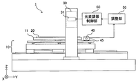
図1および図2は、本発明の一実施形態に係る露光装置1の構成を示す図である。露光装置1は、入力される画像データに基づいて空間変調された光を対象物(感光材料)に向けて照射することによりパターンを描画する。露光装置1は、フォトレジストが塗布された基板20を載置するためのステージ11と、ステージ11をY方向(主走査方向)およびX方向(副走査方向)に移動させるためのステージ移動機構10と、それぞれが空間変調されたライン状の光を基板に向けて照射する8個の描画ヘッド30と、各描画ヘッド30にそれぞれ含まれる光変調器31(詳細は後述)を入力される画像データに基づいて駆動する変調制御部60と、変調制御部60の動作を調整する調整部50とを備える。
1 and 2 are diagrams showing the configuration of an
ステージ移動機構10は、ステージ11をY方向に移動(主走査)し、主走査が終了する毎に次の主走査の開始位置へとステージ11をX方向に移動(副走査)させる。そして、次の主走査が前回の主走査とは逆向きに行われる。このように、露光装置1では、ステージ移動機構10により、ステージ11に対して8個の描画ヘッド30がX方向およびY方向へと相対的に移動可能となっている。
The
露光装置1は、ステージ移動機構10のステージ11の側に配置されたセンサ部をさらに備えている。センサ部は、描画ヘッド30からの光を受光する受光素子40と、受光素子40が上面に固定されたセンサステージ45と、センサステージ45の上面に固定されて受光素子40からの出力を演算処理するセンサ処理部44を備える。本実施形態では、受光素子40としてフォトダイオードが利用される。図1に示すように、受光素子40の受光面と基板20の上面は同じ高さに位置する。
The
上記センサ部をX方向(副走査方向)に移動させるための機構として、露光装置1には、センサステージ45が取り付けられたX方向を向くボールネジ43と、センサステージ45を支持するX方向を向く2本のガイドレール41a,41bと、ボールネジ43に接続されるモータ42が設けられている。変調制御部60のキャリブレーションの際には、モータ42によりボールネジ43が回転することにより、受光素子40およびセンサ処理部44がセンサステージ45と共にガイドレール41a,41bに沿ってX方向(副走査方向)に滑らかに移動し、描画ヘッド30からの光が受光素子40により順次受光されてセンサ処理部44に送られる。そして、センサ処理部44により演算処理されたデータが調整部50に出力される。
As a mechanism for moving the sensor unit in the X direction (sub-scanning direction), the
次に、描画ヘッド30についてより詳細に説明する。
Next, the
描画ヘッド30は、レーザ光源から出射されたレーザ光が入光される照明レンズからなる照明光学系と、光変調器31と、プリズム、結像レンズおよびレンズからなる結像光学系とを備える。レーザ光源は、ピーク波長が800nm乃至820nmの範囲にあるレーザ光を出射する光源で、照明光学系から出射されたレーザ光は、光変調器31に照射される。本実施形態では、光変調器31として回折格子型光変調素子を利用する。光変調器31の詳細は後述する。光変調器31に照射されたレーザ光は、光変調器31において多数に分割・変調された後、回折光として反射するが、回折光のうち0次回折光は、結像光学系を通じて基板20上に(キャリブレーションの際には受光素子40上に)結像される。
The
図3は、光変調器(回折格子型光変調素子)31の構造を示す平面図であり、図4はその部分斜視図である。 FIG. 3 is a plan view showing the structure of the light modulator (diffraction grating type light modulation element) 31, and FIG. 4 is a partial perspective view thereof.
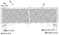
光変調器31は、図3に示すように、支持台33上に数千本(本実施形態では一例として16384本とする)の反射板(以下、リボンと称す)32を列設した構成を有する。これらのリボン32は、より詳細には図4に示すように、互い違いに配置された固定リボン32aと可動リボン32bとで構成される。リボン32の表面には、反射ミラーと電極の機能を有するように金属薄膜が形成されており、リボン32の下部には、解放層を隔てて共通電極が設けられている。
As shown in FIG. 3, the
固定リボン32aは、その表面の位置が固定された構成となっている。一方、可動リボン32bは、表面の一部の有効可動領域が、印加される電圧に応じて下降する構成となっている。各可動リボン32bに電圧が印加されていない場合には、すべての固定リボン32aの表面と可動リボン32bの表面とは、同一平面上に配置されている。可動リボン32bに電圧が印加されると、印加電圧に応じた幅だけ可動リボン32bが下降し、隣接する固定リボン32aとの高さの差により、反射型の回折格子と同様の作用を奏する。このため、光変調器31は、可動リボン32bに電圧が印加されていない状態においては照明されるレーザ光の0次回折光を反射することになり、また、可動リボン32bに電圧が印加された状態においては、正負の2本の1次回折光およびさらに高次の回折光を反射することになる。従って、光変調器31の表面にレーザ光を照明した場合には、互いに独立して変調可能な多数の回折光が得られることになる。このような光変調器31としては、上述したように、米国のシリコンライトマシーンズ社製の、GLVとも呼称されるグレイティングライトバルブ(Grating Light Valve:シリコンライトマシーンズ社の商標)を使用することができる。
The fixed
光変調器31の各可動リボン32bには個別に電圧を印加することができる。本実施形態では、光変調器31は16384本のリボン32を有し、そのうちの半数である8192本が可動リボン32bであるので、本実施形態の光変調器31は、8192個の光供給素子群で構成されていると言い換えることができる。以下では図5に示すように、光変調器31の最小制御単位(すなわち個別に電圧を制御可能な最小単位)を「チャンネル」と称する。
A voltage can be individually applied to each
変調制御部60は、入力される画像データに応じた制御値(デジタル)に基づいて、光変調器31の各可動リボン32bを駆動する。具体的には、入力される画像データに応じた各チャンネルの制御値をDA変換回路によってそれぞれ電圧に変換し、これらの電圧を各チャンネルの可動リボン32bにそれぞれ印加する。本実施形態では、入力される画像データは5段階の階調を有しており、それに伴い、変調制御部60は各チャンネルについて5段階の階調制御を行うものとする。
The
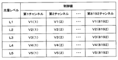
図6は、変調制御部60が光変調器31を駆動する際に参照する制御値テーブルを示している。この制御値テーブルは、変調制御部60の内部または外部に設けられた任意の記憶装置において保持されている。例えば、入力される画像データに対応する第1チャンネルの光量レベルがL1である場合には、変調制御部60は、制御値テーブルを参照して、第1チャンネルの可動リボン32bを制御値V1(1)で駆動する(すなわち、第1チャンネルの可動リボン32bに対して制御値V1(1)に対応する電圧が印加される)。同様に、入力される画像データに対応する第2チャンネルの光量レベルがL5である場合には、変調制御部60は、制御値テーブルを参照して、第2チャンネルの可動リボン32bを制御値V5(2)で駆動する(すなわち、第2チャンネルの可動リボン32bに対して制御値V5(2)に対応する電圧が印加される)。
FIG. 6 shows a control value table that is referred to when the
なお、図6に示すような制御値テーブルに基づいて、全てのチャンネルについて同一の光量レベル(例えば光量レベルL1)に対応する制御値で可動リボン32bを駆動したときに、光変調器31から出力される光量分布が一様にならないことがある。例えば、図7は、目標とする光量分布と実際の光量分布とのずれの一例を示している。そこで本実施形態では、目標とする光量分布を得るために、調整部50によってキャリブレーション処理を実行する。以下、調整部50によるキャリブレーション処理の詳細を説明する。
Note that, based on the control value table as shown in FIG. 6, when the
図8は、調整部50によるキャリブレーション処理の流れを示すフローチャートである。
FIG. 8 is a flowchart showing the flow of calibration processing by the
キャリブレーション処理が開始されると、まずステップS10において、調整部50は、プロファイル関数生成処理を実行する。プロファイル関数とは、特定のチャンネルの周辺のチャンネルの光量を固定した状態で、特定のチャンネルの光量だけを変化させたときの光量分布の変化量を表す関数である。以下、図9〜図13を参照して、プロファイル関数生成処理の詳細を説明する。
When the calibration process is started, first, in step S10, the
本実施形態では、図9に示すように、光変調器31の第1チャンネル〜第8192チャンネルを8つの区間に区分し、これらの8つの区間毎にプロファイル関数を生成する。例えば、第1区間は、第1チャンネル〜第1000チャンネルの範囲であり、第1区間用の特定チャンネルは、その範囲の中央の第500チャンネルとする。同様に、第2区間は、第1001チャンネル〜第2000チャンネルの範囲であり、第2区間用の特定チャンネルは、その範囲の中央の第1500チャンネルとする。
In the present embodiment, as shown in FIG. 9, the first channel to the 8192th channel of the
図10は、調整部50によるプロファイル関数生成処理の詳細を示すフローチャートである。なお本実施形態では、プロファイル関数の生成は、上記8つの区間毎に個別に行われる。すなわち、上記8つの区間のそれぞれについてプロファイル関数が個別に生成され、各区間のプロファイル関数に基づいて、対応する区間のキャリブレーション処理(後述する補正用関数決定処理および制御値更新処理)が行われる。
FIG. 10 is a flowchart showing details of the profile function generation processing by the
プロファイル関数生成処理が開始されると、ステップS20において、調整部50は、変調制御部60を通じて全チャンネルの可動リボン32bを中間調(例えば、最小の光量レベルと最大の光量レベルの中間のレベル)で駆動する。
When the profile function generation process is started, in step S20, the
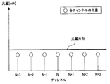
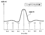
ステップS21では、調整部50は、ステージ移動機構10およびモータ42を制御することによって、描画ヘッド30の下方で受光素子40をX方向に移動させて、光変調器31から照射されるレーザ光の光量分布を計測し、計測された光量分布を任意の記憶装置に記憶する。ここで計測される光量分布の一例を図11に示す。ただし図11では、特定チャンネルの周辺領域における光量分布を示している。
In step S <b> 21, the adjusting
ステップS22では、調整部50は、残りのチャンネルの光量を上記中間調で固定にしたまま、変調制御部60を通じて特定チャンネルの光量だけを最大レベルへと変更する。
In step S <b> 22, the
ステップS23では、調整部50は、ステップS21と同様にして光変調器31から照射されるレーザ光の光量分布を計測し、計測された光量分布を任意の記憶装置に記憶する。ここで計測される光量分布の一例を図12に示す。ただし図12では、特定チャンネルの周辺領域における光量分布を示している。
In step S23, the
ステップS24では、調整部50は、ステップS21で計測された光量分布と、ステップS23で計測された光量分布との差分を計算し、当該差分をプロファイル関数f(x)として任意の記憶装置に記憶する。例えば、図13は、図11の光量分布と図12の光量分布とから計算されるプロファイル関数f(x)を示している。図13のプロファイル関数f(x)によれば、他のチャンネルの光量を固定したまま第kチャンネル(kは任意の自然数)の光量だけを増加させると、それに応じて第k−1チャンネルおよび第k+1チャンネルに対応する受光領域における受光量は減少し、第k−2および第k+2チャンネルに対応する受光領域における受光量は増加することが分かる。
In step S24, the
なお、本実施形態では、ステップS20において全チャンネルの可動リボン32bを中間調で駆動しているが、特定チャンネルの光量を変化させたときの影響は、特定チャンネルに対応する受光領域の近辺のみに及ぶので、少なくとも特定チャンネルの周辺のチャンネル(例えば、第Nチャンネルを特定チャンネルとした場合、第N−2チャンネル〜第N+2チャンネルの全5チャンネル)の可動リボン32bを中間調で駆動しさえすれば、残りのチャンネルはオフ(最小の光量レベル)にした状態であってもよい。
In this embodiment, the
また、本実施形態では、特定チャンネルの光量を他のチャンネルの光量と同じ状態から最大レベルへと変化させて、その変化の前後での光量分布の差分を計算することによってプロファイル関数f(x)を生成しているが、特定チャンネルの光量を任意のレベル(例えば最小の光量レベル)から他の任意のレベル(例えば最大の光量レベル)へと変化させて、その変化の前後での光量分布の差分を計算することによってプロファイル関数f(x)を生成してもよい。 Further, in the present embodiment, the profile function f (x) is calculated by changing the light amount of a specific channel from the same state as the light amount of other channels to the maximum level and calculating the difference in the light amount distribution before and after the change. However, the light intensity distribution of a specific channel is changed from an arbitrary level (for example, the minimum light intensity level) to another arbitrary level (for example, the maximum light intensity level). The profile function f (x) may be generated by calculating the difference.
なお、プロファイル関数f(x)を生成する際に、特定チャンネルの周辺のチャンネルの光量をオフにするのではなくて中間調にした状態で特定チャンネルの光量を変化させる理由は、特定チャンネルの光量を増加させたときに、当該特定チャンネルの光と周辺のチャンネルの光とが干渉して、周辺のチャンネルに対応する受光領域で受光量が強まるのか弱まるのかを調べるためである。 Note that when generating the profile function f (x), the light amount of the specific channel is changed in a halftone state instead of turning off the light amount of the channels around the specific channel. This is to check whether the amount of light received in the light receiving region corresponding to the peripheral channel increases or decreases due to interference between the light of the specific channel and the light of the peripheral channel.
なお、本実施形態では、8つの区間毎に1つのチャンネルを特定チャンネルとして、そのチャンネルの光量を変化させることによってプロファイル関数f(x)を生成しているが、本発明はこれに限らず、隣接する複数のチャンネルを特定チャンネルとして、それらのチャンネルの光量を変化させることによってプロファイル関数f(x)を生成するようにしてもよい。例えば、第1チャンネル〜第1000チャンネルの区間において、第499チャンネル〜第501チャンネルの隣接する3つのチャンネルを特定チャンネルとして、プロファイル関数f(x)を生成してもよい。これにより、1つのチャンネルの光量を変化させただけでは光量分布の変化が小さくてプロファイル関数f(x)を適切に生成できない場合であっても、複数のチャンネルの光量を変化させることによって光量分布の変化を大きくしてプロファイル関数f(x)を適切に生成することが可能となる。 In the present embodiment, the profile function f (x) is generated by changing the light amount of one channel as a specific channel every eight sections, but the present invention is not limited to this. The profile function f (x) may be generated by setting a plurality of adjacent channels as specific channels and changing the light quantity of those channels. For example, in the section from the first channel to the 1000th channel, the profile function f (x) may be generated using three adjacent channels of the 499th channel to the 501st channel as specific channels. As a result, even if the change in the light amount distribution is small and the profile function f (x) cannot be appropriately generated by changing the light amount of one channel, the light amount distribution can be obtained by changing the light amount of the plurality of channels. It is possible to appropriately generate the profile function f (x) by increasing the change of.
なお、プロファイル関数f(x)の形状は種々の要因によって変化し、特に経時変化もするので、キャリブレーションを実行する度にプロファイル関数を生成するのが望ましい。 Note that the shape of the profile function f (x) changes depending on various factors, and particularly changes over time. Therefore, it is desirable to generate the profile function every time calibration is executed.
なお、厳密に言うと、プロファイル関数f(x)は特定チャンネルの位置(すなわち、どのチャンネルを特定チャンネルとして設定するか)によって変化する。特に、第1チャンネルを特定チャンネルとしてプロファイル関数f(x)を生成した場合と、第8192チャンネルを特定チャンネルとしてプロファイル関数f(x)を生成した場合とでは、プロファイル関数f(x)の形状が大きく異なることも考えられる。しかしながら、比較的近い距離にあるチャンネル同士であれば、それらの各チャンネルを特定チャンネルとして生成した場合のプロファイル関数f(x)はほぼ似た形状になると予想される。したがって、本実施形態では、図9に示したように全8192チャンネルを8つの区間に分割し、これらの区間毎にそれぞれ共通のプロファイル関数f(x)を生成している。これにより、適切なキャリブレーションと、キャリブレーション時間の短縮と、記憶領域(プロファイル関数を一時的に記憶するための領域)の節約が可能である。ただし、本発明としては、必ずしも全チャンネルを複数の区間に分割して、各区間毎にプロファイル関数f(x)する必要はない。 Strictly speaking, the profile function f (x) varies depending on the position of a specific channel (that is, which channel is set as the specific channel). Particularly, when the profile function f (x) is generated with the first channel as the specific channel and when the profile function f (x) is generated with the 8192th channel as the specific channel, the shape of the profile function f (x) is It can be very different. However, if the channels are relatively close to each other, the profile function f (x) when these channels are generated as specific channels is expected to have a substantially similar shape. Therefore, in this embodiment, as shown in FIG. 9, all 8192 channels are divided into eight sections, and a common profile function f (x) is generated for each of these sections. This makes it possible to perform appropriate calibration, shorten the calibration time, and save a storage area (an area for temporarily storing a profile function). However, in the present invention, it is not always necessary to divide all channels into a plurality of sections and perform the profile function f (x) for each section.
なお、特定の区間のプロファイル関数f(x)を他の区間のプロファイル関数f(x)から補間によって求めても構わない。例えば、図9の第1区間および第3区間のプロファイル関数f(x)から、第2区間のプロファイル関数f(x)を線形補間するようにしてもよい。これにより、キャリブレーション時間の短縮と、記憶領域(プロファイル関数を一時的に記憶するための領域)の節約が可能である。 Note that the profile function f (x) of a specific section may be obtained by interpolation from the profile functions f (x) of other sections. For example, the profile function f (x) in the second section may be linearly interpolated from the profile functions f (x) in the first section and the third section in FIG. As a result, the calibration time can be shortened and the storage area (area for temporarily storing the profile function) can be saved.
図8において、ステップS10のプロファイル関数生成処理が完了すると、続くステップS11において、調整部50は補正用関数決定処理を実行する。補正用関数とは、制御値を更新するために用いる関数であって、特定チャンネル以外のチャンネルに対応する受光領域における受光量は変化させずに特定チャンネルに対応する受光領域における受光量だけを単位量(例えば1mW)だけ変化させるときの各チャンネルの光量の変化量を表す関数である。以下、図14〜図15を参照して、補正用関数決定処理の詳細を説明する。なお本実施形態では、補正用関数の決定は、図9に示した8つの区間毎に個別に行われる。すなわち、図9に示した8つの区間のそれぞれについて、プロファイル関数生成処理において生成された、対応するプロファイル関数を用いて、補正用関数が個別に決定される。
In FIG. 8, when the profile function generation process in step S10 is completed, in the subsequent step S11, the
補正用関数決定処理が開始されると、まずステップS30において、調整部50は、図8のステップS10のプロファイル関数生成処理によって生成されたプロファイル関数f(x)に基づいて、予め用意されて記憶装置に記録されている複数の典型プロファイル関数の中から、プロファイル関数f(x)に最も類似した典型プロファイル関数をパターンマッチングにより選択する。図15に、典型プロファイル関数の具体例を示す。この場合、図13のプロファイル関数f(x)に最も類似した典型プロファイル関数として、第2典型プロファイル関数が選択される。なお、パターンマッチングの手法については公知の任意の手法を用いることができる。例えば、半値幅、相関係数等の指標を用いてパターンマッチングを行ってもよい。なお、各典型プロファイル関数には、予め用意された補正用関数h(x)がそれぞれ関連付けられている。
When the correction function determination process is started, first, in step S30, the
ステップS31では、調整部50は、ステップS30で選択された典型プロファイル関数に関連付けられた補正用関数h(x)を、後述する制御値更新処理で利用すべき補正用関数h(x)として決定する。例えば、ステップS30において第2典型プロファイル関数が選択された場合には、この第2典型プロファイル関数に関連付けられた第2補正用関数を、制御値更新処理で利用すべき補正用関数h(x)として決定する。なお、プロファイル関数f(x)の形状がどのようなときに、どのような形状の補正用関数h(x)を利用すべきかは、数学的手法または経験的法則により判断することができるので、本実施形態では各典型プロファイル関数について、対応する補正用関数h(x)を数学的もしくは経験的に予め求めておき、典型プロファイル関数に関連付けている。
In step S31, the
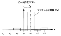
なお、予め用意された補正用関数h(x)を、プロファイル関数f(x)の形状に応じて適宜に補正してもよい。例えば、図16に示すように、プロファイル関数f(x)のピーク位置が1チャンネル分だけプラス方向にずれている場合には、図17に示すように、ステップS31で選択された補正用関数h(x)のピーク位置がマイナス方向に1チャンネル分だけシフトするように補正用関数h(x)を補正してもよい。 Note that the correction function h (x) prepared in advance may be appropriately corrected according to the shape of the profile function f (x). For example, as shown in FIG. 16, when the peak position of the profile function f (x) is shifted in the plus direction by one channel, as shown in FIG. 17, the correction function h selected in step S31. The correction function h (x) may be corrected so that the peak position of (x) is shifted by one channel in the negative direction.
なお、本実施形態では上記のように、プロファイル関数f(x)に対応する典型プロファイル関数をまず選択し、当該典型プロファイル関数に応じて補正用関数h(x)を決定しているが、本発明はこれに限らない。例えば、プロファイル関数f(x)の形状(各種特徴量)に基づいて、予め用意した複数の補正用関数h(x)の中から最適な補正用関数h(x)を予め用意した選択基準にしたがって調整部50が自動的に選択するようにしても構わない。また例えば、調整部50がリアルタイムに、プロファイル関数f(x)から補正用関数h(x)を数学的に計算するようにしても構わない。
In the present embodiment, as described above, the typical profile function corresponding to the profile function f (x) is first selected, and the correction function h (x) is determined according to the typical profile function. The invention is not limited to this. For example, an optimal correction function h (x) is selected from a plurality of correction functions h (x) prepared in advance based on the shape (various feature amounts) of the profile function f (x). Therefore, you may make it the
図8において、ステップS11の補正用関数決定処理が完了すると、続くステップS12において、調整部50は制御値更新処理を実行する。以下、図18〜図22を参照して、制御値更新処理の詳細を説明する。なお本実施形態では、制御値の更新は、図9に示した8つの区間毎に個別に行われる。すなわち、図9に示した8つの区間のそれぞれについて、補正用関数決定処理において生成された、対応する補正用関数を用いて、制御値が個別に更新される。
In FIG. 8, when the correction function determination process in step S11 is completed, in the subsequent step S12, the
制御値更新処理が開始されると、まずステップS40において、調整部50は、変調制御部60を通じて全チャンネルの可動リボン32bを、目標とする光量分布に対応する制御値で駆動する。例えば、図6に示す制御値テーブルにおいて、光量レベルL1の各チャンネルの制御値をキャリブレーションしたい場合には、第1チャンネルを制御値V1(1)で、第2チャンネルを制御値V1(2)で、第3チャンネルを制御値V1(3)で、・・・、第8192チャンネルを制御値V1(8192)で、それぞれ駆動する。同様に、光量レベルL2の各チャンネルの制御値をキャリブレーションしたい場合には、第1チャンネルを制御値V2(1)で、第2チャンネルを制御値V2(2)で、第3チャンネルを制御値V2(3)で、・・・、第8192チャンネルを制御値V2(8192)で、それぞれ駆動する。以下では、光量レベルL1の各チャンネルの制御値をキャリブレーションする場合について説明する。なお、ステップS40において、全チャンネルの可動リボン32bを目標とする光量分布に対応する制御値で駆動する替わりに、各チャンネルの可動リボン32bを任意の光量レベルで駆動しても構わない。
When the control value update process is started, first, in step S40, the
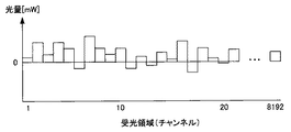
ステップS41では、調整部50は、ステップS21と同様にして光変調器31から照射されるレーザ光の光量分布を計測し、計測された光量分布を任意の記憶装置に記憶する。ここで計測される光量分布の一例を図19に示す。
In step S41, the
ステップS42では、調整部50は、ステップS41で計測された実際の光量分布と、目標とする光量分布との差分g(x)(すなわち、各チャンネルに対応する受光領域毎の「目標とする受光量」と「実際の受光量」の差分を表す関数)を計算する。ここで計算される差分g(x)の一例を図20に示す。
In step S42, the adjusting
ステップS43では、調整部50は、ステップS42で計算された差分g(x)と、前述の図8のステップS11の補正用関数決定処理において決定された、対応する区間の補正用関数h(x)とを畳み込み積分することによって、各チャンネルの制御値の補正量を計算する。ここで計算される各チャンネルの制御値の補正量の一例を図21に示す。図21において、C(1)、C(2)、C(3)およびC(8192)は、それぞれ、第1チャンネルの制御値の補正量、第2チャンネルの制御値の補正量、第3チャンネルの制御値の補正量および第8192チャンネルの制御値の補正量を示している。
In step S43, the
ステップS44では、調整部50は、ステップS43で計算された各チャンネルの制御値の補正量に従って、図6に示す制御値テーブルの中の該当する制御値を更新する。具体的には、図22に示すように、光量レベルL1に対応する更新前の第1チャンネルの制御値V1(1)_oldに対して補正量C(1)を加算することによって、光量レベルL1に対応する更新後の第1チャンネルの制御値V1(1)_newが決定される。同様に、光量レベルL1に対応する更新前の第2チャンネルの制御値V1(2)_oldに対して補正量C(2)を加算することによって、光量レベルL1に対応する更新後の第2チャンネルの制御値V1(2)_newが決定される。残りのチャンネルについても同様である。
In step S44, the
なお、上記ステップS43では、各チャンネルの制御値と光量の関係が線形性であると仮定して、各チャンネルの制御値の補正量を求めている。しかしながら、各チャンネルの制御値と光量の関係が線形でない場合(もしくは、線形であると近似することが不適当な場合)には、ステップS43で得られた各チャンネルの補正量の値を、例えば図23に示すような制御値と光量の関係(非線形的な関係)を示す光量特性曲線に基づいて、適宜に補正しても構わない。 In step S43, the correction amount of the control value of each channel is obtained on the assumption that the relationship between the control value of each channel and the amount of light is linear. However, if the relationship between the control value of each channel and the amount of light is not linear (or if it is inappropriate to approximate it to be linear), the value of the correction amount of each channel obtained in step S43 is, for example, Correcting may be performed as appropriate based on a light amount characteristic curve indicating the relationship between the control value and the light amount (non-linear relationship) as shown in FIG.
また、ステップS43で得られた各チャンネルの補正量の値をPID制御により適宜に補正しても構わない。 Further, the value of the correction amount of each channel obtained in step S43 may be appropriately corrected by PID control.
上記のようなキャリブレーション処理が完了すると、理想的には、更新後の制御値に基づいて光変調器31から出力される光量分布は目標とする光量分布に完全に一致するはずであるが、実際には種々の要因により、例えば図24のように、更新後の制御値に基づいて光変調器31から実際に出力される光量分布が目標とする光量分布に完全に一致することはない。通常は、図8のステップS12の制御値更新処理を繰り返し実行することにより、光変調器31から実際に出力される光量分布が目標とする光量分布に徐々に近づくことになる。しかしながら、特殊なケースにおいては、制御値更新処理を繰り返すほど、光変調器31から実際に出力される光量分布と目標とする光量分布との差が逆に広がっていってしまうことがある。そのような状況が起こる典型的なケースとして、ステップS11の補正用関数決定処理において不適当な補正用関数h(x)を選択してしまったケースがある。したがって、図8のステップS12の制御値更新処理の後に、キャリブレーション処理の効果を検証するための検証処理を行うことが望ましい。以下、図25を参照して、この検証処理について説明する。
When the calibration process as described above is completed, ideally, the light amount distribution output from the
検証処理が開始されると、まずステップS50において、調整部50は、変調制御部60を通じて全チャンネルの可動リボン32bを、直前の制御値更新処理によって更新された後の制御値でそれぞれ駆動する。
When the verification process is started, first, in step S50, the
ステップS51では、調整部50は、ステップS21と同様にして光変調器31から照射されるレーザ光の光量分布を計測し、計測された光量分布を任意の記憶装置に記憶する。
In step S51, the
ステップS52では、調整部50は、ステップS51で計測された実際の光量分布の目標光量分布に対する誤差が許容範囲に収まったかどうか(すなわち、制御値の再更新が不要かどうか)を判断し、誤差が許容範囲に収まった場合には検証処理を終了し、誤差が許容範囲に収まっていない場合には処理はステップS53に進む。なお、誤差が許容範囲に収まったかどうかの判断手法としては、公知の種々の手法の中から要求精度に応じた任意の手法を用いればよい。例えば、誤差を表す指標として、二乗平均誤差、SNR(signal-to-noise ratio)、相関係数等を利用してもよい。
In step S52, the
ステップS53では、調整部50は、ステップS51で計測された実際の光量分布の目標光量分布に対する誤差が、直前に行われた制御値更新処理の実行前のものと比較して縮小したかどうかを判断し、誤差が縮小した場合にはステップS55に進み、誤差が縮小していない場合にはステップS54に進む。
In step S53, the
ステップS51で計測された実際の光量分布の目標光量分布に対する誤差が、直前に行われた制御値更新処理の実行前のものと比較して縮小していないということは、その制御値更新処理において利用した補正用関数h(x)が適切ではなかったことを意味する。したがって、ステップS53では、調整部50は、補正用関数h(x)が適切かどうかを判定しているとも言える。
The fact that the error of the actual light amount distribution measured in step S51 with respect to the target light amount distribution is not reduced as compared with the one before the execution of the control value update process performed immediately before is the control value update process. This means that the correction function h (x) used is not appropriate. Therefore, in step S53, it can be said that the
ステップS54では、調整部50は、補正用関数h(x)を変更する。例えば、予め用意されている複数の補正用関数h(x)の中から、直前に行われた制御値更新処理で利用した補正用関数h(x)とは別の補正用関数h(x)を選択する。
In step S54, the
ステップS55では、調整部50は、制御値更新処理を行う。この制御値更新処理は、図8のステップS12の制御値更新処理と同じであるので、ここでは説明を省略する。
In step S55, the
ステップS55の制御値更新処理が終了すると、処理はステップS50に戻る。 When the control value update process in step S55 ends, the process returns to step S50.
上記のような検証処理によって、光変調器31から実際に出力される光量分布と目標とする光量分布との間の誤差が許容範囲に収まるまで、必要に応じて補正用関数h(x)を変更しながら、制御値更新処理が繰り返される。なお、制御値更新処理を一定回数以上繰り返しても光変調器31から実際に出力される光量分布と目標とする光量分布との間の誤差が許容範囲に収まらない場合には、ユーザにエラー通知を行うなどしてキャリブレーション処理を終了してもよい。
The correction function h (x) is applied as necessary until the error between the light amount distribution actually output from the
以上のように、本実施形態によれば、光変調器31の光量分布を高精度に補正することができる。
As described above, according to the present embodiment, the light amount distribution of the
なお、本実施形態では、光変調器31として回折格子型光変調素子を利用しているが、本発明はライン状に並んだ光供給素子群から対象物に向けて光を発するように構成された露光装置に適用可能である。ライン状に並んだ光供給素子群としては、本実施形態のような反射型に限らず、自発光型であってもよいし、透過型であってもよい。
In this embodiment, a diffraction grating type light modulation element is used as the
なお、本実施形態において示した描画ヘッド30の個数、光変調器31におけるリボン32の個数、画像データの階調数等の数値は単なる一例に過ぎず、これらの数値に限定されるものではない。
The numerical values such as the number of drawing heads 30, the number of
本発明は、ライン状に並んだ光供給素子群から対象物に向けて光を発するように構成された、コヒーレンシーが高いレーザー等の光を用いる露光装置において、各光供給素子から供給される光量を高精度に補正するキャリブレーション方法として好適である。 The present invention provides a light quantity supplied from each light supply element in an exposure apparatus using light such as a laser having high coherency, which is configured to emit light toward a target from a group of light supply elements arranged in a line. This is suitable as a calibration method for correcting the image with high accuracy.
1 露光装置
10 ステージ移動機構
11 ステージ
20 基板
30 描画ヘッド
31 光変調器
32 反射板(リボン)
32a 固定リボン
32b 可動リボン
33 支持台
40 受光素子
41a,41b ガイドレール
42 モータ
43 ボールネジ
44 センサ処理部
45 センサステージ
50 調整部
60 変調制御部
DESCRIPTION OF
32a Fixed
Claims (11)
前記光供給素子群のうち、特定の光供給素子の周辺に位置する周辺光供給素子から光を供給する周辺発光工程と、
前記周辺光供給素子の光量を固定した状態で、前記特定の光供給素子の光量を第1の光量レベルから第2の光量レベルへと変化させる光量変化工程と、
前記光量変化工程において前記特定の光供給素子の光量を変化させたときの前記光供給素子群から供給される光の光量分布の変化量を計測することによって、前記特定の光供給素子の光量のみを変化させたときの前記光供給素子群から供給される光の光量分布の変化量を表すプロファイル関数を生成して記憶装置に記憶するプロファイル関数生成工程と、
各光供給素子を駆動するための制御値を前記プロファイル関数に基づいて較正する較正工程とを備えた、キャリブレーション方法。 A calibration method for correcting the amount of light supplied from each light supply element in an exposure apparatus configured to emit light toward an object from a group of light supply elements arranged in a line,
A peripheral light emitting step of supplying light from an ambient light supply element located around a specific light supply element in the light supply element group;
A light amount changing step of changing the light amount of the specific light supply element from the first light amount level to the second light amount level in a state where the light amount of the peripheral light supply element is fixed;
Only the light amount of the specific light supply element is measured by measuring the amount of change in the light amount distribution of the light supplied from the light supply element group when the light amount of the specific light supply element is changed in the light amount change step. A profile function generation step of generating a profile function representing a change amount of the light amount distribution of the light supplied from the light supply element group when it is changed and storing it in a storage device;
And a calibration step of calibrating a control value for driving each light supply element based on the profile function.
前記プロファイル関数に基づいて補正用関数を決定する補正用関数決定工程と、
各光供給素子を予め定められた個別の制御値でそれぞれ駆動することによって前記光供給素子群から光を供給する発光工程と、
前記光供給素子群から供給される光の光量分布を計測する光量分布計測工程と、
前記光量分布計測工程において計測された光量分布と目標光量分布との差分を計算する差分計算工程と、
前記差分と前記補正用関数の畳み込み積分によって、各光供給素子の制御値の補正量をそれぞれ計算する補正量計算工程と、
前記発光工程で用いた各光供給素子の制御値を前記補正量計算工程において算出された各光供給素子の制御値の補正量に応じて補正することによって、前記目標光量分布を実現するための各光供給素子の制御値を更新する制御値更新工程とを含むことを特徴とする、請求項1に記載のキャリブレーション方法。 The calibration step includes
A correction function determining step for determining a correction function based on the profile function;
A light emitting step of supplying light from the light supply element group by driving each light supply element with a predetermined individual control value;
A light amount distribution measuring step for measuring a light amount distribution of light supplied from the light supply element group;
A difference calculating step for calculating a difference between the light amount distribution measured in the light amount distribution measuring step and the target light amount distribution;
A correction amount calculating step of calculating a correction amount of the control value of each light supply element by convolution integration of the difference and the correction function;
By correcting the control value of each light supply element used in the light emission step according to the correction amount of the control value of each light supply element calculated in the correction amount calculation step, to realize the target light amount distribution The calibration method according to claim 1, further comprising a control value update step of updating a control value of each light supply element.
前記光供給素子群から供給される光の光量分布を計測する光量分布再計測工程と、
前記光量分布再計測工程において計測された光量分布に基づいて、前記目標光量分布を実現するための各光供給素子の制御値を再更新する必要があるか否かを判定する較正結果評価工程とを更に備え、
前記較正結果評価工程において各光供給素子の制御値を再度更新する必要があると判定されたときに、前記光量分布計測工程において計測された光量分布に代わりに前記光量分布再計測工程において計測された光量分布を用いて、前記差分計算工程、前記補正量計算工程および前記制御値更新工程を再実行することを特徴とする、請求項3に記載のキャリブレーション方法。 A re-emission step of supplying light from the light supply element group by driving each light supply element with the control value updated by the control value update step;
A light amount distribution re-measurement step of measuring a light amount distribution of light supplied from the light supply element group;
A calibration result evaluation step for determining whether or not it is necessary to re-update the control value of each light supply element for realizing the target light amount distribution based on the light amount distribution measured in the light amount distribution re-measurement step; Further comprising
When it is determined in the calibration result evaluation step that the control value of each light supply element needs to be updated again, it is measured in the light amount distribution re-measurement step instead of the light amount distribution measured in the light amount distribution measurement step. The calibration method according to claim 3, wherein the difference calculation step, the correction amount calculation step, and the control value update step are re-executed using the obtained light amount distribution.
前記光供給素子群から供給される光の光量分布を計測する光量分布再計測工程と、
前記光量分布再計測工程において計測された光量分布に基づいて、前記補正用関数決定工程において決定した補正用関数が適切であるか否かを判定する補正用関数評価工程と、
前記補正用関数評価工程において前記補正用関数が適切でないと判定されたときに補正用関数を変更する補正用関数変更工程とをさらに備え、
前記補正用関数変更工程において変更された新たな補正用関数を用いて、前記発光工程、前記光量分布計測工程、前記差分計算工程、前記補正量計算工程および前記制御値更新工程を再実行することを特徴とする、請求項3に記載のキャリブレーション方法。 A re-emission step of supplying light from the light supply element group by driving each light supply element with the control value updated by the control value update step;
A light amount distribution re-measurement step of measuring a light amount distribution of light supplied from the light supply element group;
A correction function evaluation step for determining whether or not the correction function determined in the correction function determination step is appropriate based on the light amount distribution measured in the light amount distribution re-measurement step;
A correction function changing step of changing the correction function when it is determined that the correction function is not appropriate in the correction function evaluation step,
Using the new correction function changed in the correction function changing step, the light emission step, the light amount distribution measurement step, the difference calculation step, the correction amount calculation step, and the control value update step are re-executed. The calibration method according to claim 3, wherein:
Priority Applications (1)
| Application Number | Priority Date | Filing Date | Title |
|---|---|---|---|
| JP2008231475A JP5124400B2 (en) | 2008-09-09 | 2008-09-09 | Exposure power calibration method |
Applications Claiming Priority (1)
| Application Number | Priority Date | Filing Date | Title |
|---|---|---|---|
| JP2008231475A JP5124400B2 (en) | 2008-09-09 | 2008-09-09 | Exposure power calibration method |
Publications (2)
| Publication Number | Publication Date |
|---|---|
| JP2010066415A true JP2010066415A (en) | 2010-03-25 |
| JP5124400B2 JP5124400B2 (en) | 2013-01-23 |
Family
ID=42192068
Family Applications (1)
| Application Number | Title | Priority Date | Filing Date |
|---|---|---|---|
| JP2008231475A Expired - Fee Related JP5124400B2 (en) | 2008-09-09 | 2008-09-09 | Exposure power calibration method |
Country Status (1)
| Country | Link |
|---|---|
| JP (1) | JP5124400B2 (en) |
Cited By (4)
| Publication number | Priority date | Publication date | Assignee | Title |
|---|---|---|---|---|
| JP2011066087A (en) * | 2009-09-15 | 2011-03-31 | Tohoku Univ | Exposure device, and exposure method |
| JP2013197148A (en) * | 2012-03-16 | 2013-09-30 | Dainippon Screen Mfg Co Ltd | Inspection apparatus, exposure device and inspection method |
| JP2014174287A (en) * | 2013-03-07 | 2014-09-22 | V Technology Co Ltd | Scanning exposure device and scanning exposure method |
| JP2016071135A (en) * | 2014-09-30 | 2016-05-09 | 株式会社Screenホールディングス | Drawing method |
Citations (4)
| Publication number | Priority date | Publication date | Assignee | Title |
|---|---|---|---|---|
| JPH1110942A (en) * | 1997-06-23 | 1999-01-19 | Futaba Corp | Method for measuring and correcting quantity of light of light emitting dot and light source for printer |
| JP2002059584A (en) * | 2000-08-23 | 2002-02-26 | Minolta Co Ltd | Luminous energy correction method for exposure means and image forming device |
| JP2002356007A (en) * | 2001-03-26 | 2002-12-10 | Fuji Xerox Co Ltd | Print head and method of correcting quantity of light exposure |
| JP2007121998A (en) * | 2005-09-29 | 2007-05-17 | Dainippon Screen Mfg Co Ltd | Image recording apparatus and method therefor |
-
2008
- 2008-09-09 JP JP2008231475A patent/JP5124400B2/en not_active Expired - Fee Related
Patent Citations (4)
| Publication number | Priority date | Publication date | Assignee | Title |
|---|---|---|---|---|
| JPH1110942A (en) * | 1997-06-23 | 1999-01-19 | Futaba Corp | Method for measuring and correcting quantity of light of light emitting dot and light source for printer |
| JP2002059584A (en) * | 2000-08-23 | 2002-02-26 | Minolta Co Ltd | Luminous energy correction method for exposure means and image forming device |
| JP2002356007A (en) * | 2001-03-26 | 2002-12-10 | Fuji Xerox Co Ltd | Print head and method of correcting quantity of light exposure |
| JP2007121998A (en) * | 2005-09-29 | 2007-05-17 | Dainippon Screen Mfg Co Ltd | Image recording apparatus and method therefor |
Cited By (4)
| Publication number | Priority date | Publication date | Assignee | Title |
|---|---|---|---|---|
| JP2011066087A (en) * | 2009-09-15 | 2011-03-31 | Tohoku Univ | Exposure device, and exposure method |
| JP2013197148A (en) * | 2012-03-16 | 2013-09-30 | Dainippon Screen Mfg Co Ltd | Inspection apparatus, exposure device and inspection method |
| JP2014174287A (en) * | 2013-03-07 | 2014-09-22 | V Technology Co Ltd | Scanning exposure device and scanning exposure method |
| JP2016071135A (en) * | 2014-09-30 | 2016-05-09 | 株式会社Screenホールディングス | Drawing method |
Also Published As
| Publication number | Publication date |
|---|---|
| JP5124400B2 (en) | 2013-01-23 |
Similar Documents
| Publication | Publication Date | Title |
|---|---|---|
| US6965119B2 (en) | Method and apparatus of calibrating multi-position SLM elements | |
| JP4771753B2 (en) | Surface light source control apparatus and surface light source control method | |
| JP4778834B2 (en) | Image recording method and apparatus | |
| TWI432913B (en) | Lithographic system, device manufacturing method, setpoint data optimization method, and apparatus for producing optimized setpoint data | |
| JP5124400B2 (en) | Exposure power calibration method | |
| JP2008090264A (en) | Method and apparatus for correcting output light-amounts of spatial light modulator, image recording apparatus and image recording method | |
| KR101678070B1 (en) | Maskless Exposure Apparatus and Control Method Thereof | |
| JP5180446B2 (en) | Exposure apparatus and exposure method | |
| US20070091164A1 (en) | Laser diode modulator and method of controlling laser diode modulator | |
| KR20080089173A (en) | Exposure apparatus and exposure method for exposure apparatus | |
| US7957043B2 (en) | Image recording apparatus and image recording method | |
| JP2005208641A (en) | Parallel beam to beam uniformity correction | |
| US6603499B2 (en) | Printhead having non-uniformity correction based on spatial energy profile data, a method for non-uniformity correction of a printhead, and an apparatus for measuring spatial energy profile data in a printhead | |
| JP2010026465A (en) | Pattern drawing device | |
| US9891537B2 (en) | Maskless lithographic apparatus measuring accumulated amount of light | |
| KR102289733B1 (en) | Maskless exposure method and maskless exposure device for performing the exposure method | |
| JP2005208642A (en) | Parallel beam to beam uniformity correction | |
| US20030189635A1 (en) | Method for calibrating spatial light modulator against profile | |
| EP1596571A2 (en) | Reduction of imaging artifacts in a platesetter having a diffractive modulator. | |
| JP6747899B2 (en) | Laser marking device and method for adjusting density thereof | |
| JP2018163010A (en) | Measuring method and measuring device | |
| JP4806581B2 (en) | Light amount adjusting method, image recording method and apparatus | |
| KR20120100209A (en) | Maskless exposure apparatus and method for stitching exposure using the same | |
| KR20160046016A (en) | Maskless exposure device and method for compensating cumulative of illumination using the same | |
| JP2004004717A (en) | Method and system for focus control within imaging engine using spatial light modulator |
Legal Events
| Date | Code | Title | Description |
|---|---|---|---|
| A621 | Written request for application examination |
Free format text: JAPANESE INTERMEDIATE CODE: A621 Effective date: 20110606 |
|
| RD02 | Notification of acceptance of power of attorney |
Free format text: JAPANESE INTERMEDIATE CODE: A7422 Effective date: 20110830 |
|
| A977 | Report on retrieval |
Free format text: JAPANESE INTERMEDIATE CODE: A971007 Effective date: 20121009 |
|
| TRDD | Decision of grant or rejection written | ||
| A01 | Written decision to grant a patent or to grant a registration (utility model) |
Free format text: JAPANESE INTERMEDIATE CODE: A01 Effective date: 20121016 |
|
| A01 | Written decision to grant a patent or to grant a registration (utility model) |
Free format text: JAPANESE INTERMEDIATE CODE: A01 |
|
| A61 | First payment of annual fees (during grant procedure) |
Free format text: JAPANESE INTERMEDIATE CODE: A61 Effective date: 20121029 |
|
| FPAY | Renewal fee payment (prs date is renewal date of database) |
Free format text: PAYMENT UNTIL: 20151102 Year of fee payment: 3 |
|
| R150 | Certificate of patent (=grant) or registration of utility model |
Free format text: JAPANESE INTERMEDIATE CODE: R150 |
|
| S533 | Written request for registration of change of name |
Free format text: JAPANESE INTERMEDIATE CODE: R313533 |
|
| R350 | Written notification of registration of transfer |
Free format text: JAPANESE INTERMEDIATE CODE: R350 |
|
| LAPS | Cancellation because of no payment of annual fees |