JP2010065688A - Steam turbine having stage with buckets of different materials - Google Patents
Steam turbine having stage with buckets of different materials Download PDFInfo
- Publication number
- JP2010065688A JP2010065688A JP2009204186A JP2009204186A JP2010065688A JP 2010065688 A JP2010065688 A JP 2010065688A JP 2009204186 A JP2009204186 A JP 2009204186A JP 2009204186 A JP2009204186 A JP 2009204186A JP 2010065688 A JP2010065688 A JP 2010065688A
- Authority
- JP
- Japan
- Prior art keywords
- buckets
- stage
- steam turbine
- bucket
- cover
- Prior art date
- Legal status (The legal status is an assumption and is not a legal conclusion. Google has not performed a legal analysis and makes no representation as to the accuracy of the status listed.)
- Withdrawn
Links
Images


Classifications
-
- F—MECHANICAL ENGINEERING; LIGHTING; HEATING; WEAPONS; BLASTING
- F01—MACHINES OR ENGINES IN GENERAL; ENGINE PLANTS IN GENERAL; STEAM ENGINES
- F01D—NON-POSITIVE DISPLACEMENT MACHINES OR ENGINES, e.g. STEAM TURBINES
- F01D5/00—Blades; Blade-carrying members; Heating, heat-insulating, cooling or antivibration means on the blades or the members
- F01D5/12—Blades
- F01D5/14—Form or construction
- F01D5/16—Form or construction for counteracting blade vibration
-
- F—MECHANICAL ENGINEERING; LIGHTING; HEATING; WEAPONS; BLASTING
- F01—MACHINES OR ENGINES IN GENERAL; ENGINE PLANTS IN GENERAL; STEAM ENGINES
- F01D—NON-POSITIVE DISPLACEMENT MACHINES OR ENGINES, e.g. STEAM TURBINES
- F01D5/00—Blades; Blade-carrying members; Heating, heat-insulating, cooling or antivibration means on the blades or the members
- F01D5/02—Blade-carrying members, e.g. rotors
- F01D5/027—Arrangements for balancing
-
- F—MECHANICAL ENGINEERING; LIGHTING; HEATING; WEAPONS; BLASTING
- F05—INDEXING SCHEMES RELATING TO ENGINES OR PUMPS IN VARIOUS SUBCLASSES OF CLASSES F01-F04
- F05C—INDEXING SCHEME RELATING TO MATERIALS, MATERIAL PROPERTIES OR MATERIAL CHARACTERISTICS FOR MACHINES, ENGINES OR PUMPS OTHER THAN NON-POSITIVE-DISPLACEMENT MACHINES OR ENGINES
- F05C2201/00—Metals
- F05C2201/04—Heavy metals
- F05C2201/0433—Iron group; Ferrous alloys, e.g. steel
- F05C2201/0466—Nickel
-
- F—MECHANICAL ENGINEERING; LIGHTING; HEATING; WEAPONS; BLASTING
- F05—INDEXING SCHEMES RELATING TO ENGINES OR PUMPS IN VARIOUS SUBCLASSES OF CLASSES F01-F04
- F05D—INDEXING SCHEME FOR ASPECTS RELATING TO NON-POSITIVE-DISPLACEMENT MACHINES OR ENGINES, GAS-TURBINES OR JET-PROPULSION PLANTS
- F05D2240/00—Components
- F05D2240/10—Stators
- F05D2240/11—Shroud seal segments
-
- F—MECHANICAL ENGINEERING; LIGHTING; HEATING; WEAPONS; BLASTING
- F05—INDEXING SCHEMES RELATING TO ENGINES OR PUMPS IN VARIOUS SUBCLASSES OF CLASSES F01-F04
- F05D—INDEXING SCHEME FOR ASPECTS RELATING TO NON-POSITIVE-DISPLACEMENT MACHINES OR ENGINES, GAS-TURBINES OR JET-PROPULSION PLANTS
- F05D2260/00—Function
- F05D2260/96—Preventing, counteracting or reducing vibration or noise
- F05D2260/961—Preventing, counteracting or reducing vibration or noise by mistuning rotor blades or stator vanes with irregular interblade spacing, airfoil shape
-
- F—MECHANICAL ENGINEERING; LIGHTING; HEATING; WEAPONS; BLASTING
- F05—INDEXING SCHEMES RELATING TO ENGINES OR PUMPS IN VARIOUS SUBCLASSES OF CLASSES F01-F04
- F05D—INDEXING SCHEME FOR ASPECTS RELATING TO NON-POSITIVE-DISPLACEMENT MACHINES OR ENGINES, GAS-TURBINES OR JET-PROPULSION PLANTS
- F05D2300/00—Materials; Properties thereof
- F05D2300/10—Metals, alloys or intermetallic compounds
- F05D2300/17—Alloys
- F05D2300/171—Steel alloys
-
- F—MECHANICAL ENGINEERING; LIGHTING; HEATING; WEAPONS; BLASTING
- F05—INDEXING SCHEMES RELATING TO ENGINES OR PUMPS IN VARIOUS SUBCLASSES OF CLASSES F01-F04
- F05D—INDEXING SCHEME FOR ASPECTS RELATING TO NON-POSITIVE-DISPLACEMENT MACHINES OR ENGINES, GAS-TURBINES OR JET-PROPULSION PLANTS
- F05D2300/00—Materials; Properties thereof
- F05D2300/50—Intrinsic material properties or characteristics
- F05D2300/502—Thermal properties
- F05D2300/5021—Expansivity
- F05D2300/50212—Expansivity dissimilar
Abstract
Description
本発明は、広義には蒸気タービンに関する。具体的には、本発明は、異なる材料の一体カバー付きバケットを含む蒸気タービン段に関する。 The present invention relates generally to steam turbines. Specifically, the present invention relates to a steam turbine stage that includes buckets with integral covers of different materials.
蒸気タービンの蒸気流路は概して固定ケーシングとロータとで形成される。このような構成では、何枚かの固定静翼が周方向列の形態で蒸気流路に内向きに延在するようにケーシングに取付けられる。同様に、何枚かの回転動翼が周方向列の形態で蒸気流路に外向きに延在するようにロータの回転シャフトに取付けられ。固定静翼と回転動翼は交互に列をなすように配置され、静翼列及び直ぐ下流の動翼列は段を形成する。静翼は蒸気の流れが下流の動翼列に正しい角度で流入するように、蒸気の流れを導く働きをする。動翼の翼形部は、蒸気からエネルギーを抽出してロータ及び該ロータに取付けられた負荷を駆動するのに必要な動力を発生させる。 The steam flow path of a steam turbine is generally formed by a fixed casing and a rotor. In such a configuration, several stationary vanes are attached to the casing so as to extend inwardly into the steam flow path in the form of a circumferential row. Similarly, a number of rotating blades are attached to the rotor's rotating shaft so that they extend outwardly into the steam flow path in the form of circumferential rows. The stationary stationary blades and the rotating blades are alternately arranged in rows, and the stationary blade row and the immediately downstream moving blade row form a stage. The stationary vanes serve to direct the steam flow so that the steam flows into the downstream blade row at the correct angle. The blade airfoil extracts the energy from the steam and generates the power necessary to drive the rotor and the load attached to the rotor.
蒸気が蒸気タービンを流れると、その圧力は各段毎に所望の吐出圧に達するまで順次降下する。従って、温度、圧力、速度及び水分量のような蒸気特性は、蒸気が流路を通って膨張する際に列毎に異なる。その結果、各動翼列には、その列に付随した蒸気条件に対して最適化された翼形状の動翼が用いられる。翼形状に加えて、バケットは、組立て時及び使用時に列内の隣接バケットのカバーとの接触を保つ寸法及び位置の一体カバーで終端する。この構造には、2つの理由が存在する。第一に、カバーを絶えず接触させることは、隣接バケット、カバー、静翼インタフェース間の間隙を減少及び/又は排除することによって蒸気通路性能を高める。第二に、隣接バケットとカバーが連続して接触していないバケットは、「自立状態」になり、これにより損傷が生じる。連続カバー接触を維持することは、例えば約975°Fを超える用途では、静翼及び/又はロータインタフェースの長期クリープの発生のために設計上困難な課題となる。最新の解決法では、一体カバー付きバケットに対してニッケル基合金のような高性能材料を使用するか或いはクリープが制限要因となるような蒸気タービンの領域にピーニング処理した(別体の)カバーを備えたステンレス鋼合金バケットを使用する。 As the steam flows through the steam turbine, the pressure drops sequentially until the desired discharge pressure is reached for each stage. Thus, vapor properties such as temperature, pressure, velocity and moisture content vary from column to column as the vapor expands through the flow path. As a result, each blade row uses a blade shape blade optimized for the steam conditions associated with that row. In addition to the wing shape, the buckets terminate with an integral cover that is sized and positioned to maintain contact with the cover of adjacent buckets in the row during assembly and use. There are two reasons for this structure. First, the constant contact of the cover enhances steam path performance by reducing and / or eliminating gaps between adjacent buckets, covers, and vane interfaces. Second, buckets where adjacent buckets and covers are not in continuous contact are “self-supporting”, which causes damage. Maintaining continuous cover contact is a difficult design challenge due to the occurrence of long-term creep of the vane and / or rotor interface, for example in applications above about 975 ° F. The latest solution is to use a high performance material such as a nickel-based alloy for the bucket with integral cover, or a peened (separate) cover in the steam turbine area where creep is a limiting factor. Use the stainless steel alloy bucket provided.
本発明の第1の態様では、複数のバケットを含む段を含む蒸気タービンであって、複数のバケットが、第1の材料からなる第1のバケットの組と、第1の材料とは異なる第2の材料からなる第2のバケットの組とを含む、蒸気タービンを提供する。 In a first aspect of the present invention, a steam turbine including a stage including a plurality of buckets, wherein the plurality of buckets is different from the first material set and the first material. And a second set of buckets of two materials.
本発明の第2の態様では、蒸気タービン用の複数のバケットの段であって、第1の材料からなる第1のバケットの組と、第1の材料とは異なる第2の材料からなる第2のバケットの組とを含むバケット段を提供する。 In a second aspect of the present invention, a plurality of bucket stages for a steam turbine, a first set of buckets made of a first material and a second material made of a second material different from the first material. A bucket stage including two bucket sets is provided.
以下、蒸気タービンに関する用途及び作動を例にとって、本発明の1以上の実施形態について説明する。ただし、本発明が適宜どのようなタービン及び/又はエンジンにも同様に応用できることは、本明細書の教示内容に接した当業者には明らかであろう。本発明の実施形態は、異なる材料のバケットを含む段を有する蒸気タービンを提供する。 In the following, one or more embodiments of the present invention will be described taking applications and operations relating to a steam turbine as an example. However, it will be apparent to those skilled in the art, given the teachings herein, that the present invention is equally applicable to any turbine and / or engine as appropriate. Embodiments of the present invention provide a steam turbine having a stage that includes buckets of different materials.
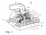
図面を参照すると、図1は、蒸気タービン10の一部切欠き斜視図を示す。蒸気タービン10は、回転シャフト14及び複数の軸方向に離隔したロータホイール18を備えたロータ12を含む。複数の回転動翼20が、各ロータホイール18に対して機械的に結合される。具体的には、動翼20は各ロータホイール18の周方向の列として配置される。複数の固定静翼22がシャフト14の周方向に配置され、軸方向には隣接動翼20列の間に位置する。固定静翼22は動翼20と協働してタービン段を形成し、タービン10を通る蒸気流路の一部を形成する。
Referring to the drawings, FIG. 1 shows a partially cutaway perspective view of a
作動中に、蒸気24は、タービン10の入口26に流入しかつ固定タービン22を通して送られる。静翼22は蒸気24を下流の動翼20に向ける。蒸気24は、残りの段を通って流れ、動翼20に力を与えてシャフト14を回転させる。タービン10の少なくとも一端は軸方向にロータ12と遠位方向に延在していてもよく、特に限定されないが、発電機その他のタービンのような負荷又は機械(図示せず)に取付けることができる。
During operation, steam 24 enters the inlet 26 of the
図1に示すような本発明の一実施形態では、タービン10は、5つの段を含む。5つの段は、L0、L1、L2、L3及びL4と呼ばれる。段L4は第1段であって5段のうちで最小(半径方向に)のものである。段L3は、第2であって軸方向における次の段である。段L2は、第3であって5段のうちの中央に位置するものとして示す。段L1は、第4であって最後から2番目の段である。段L0は、最終段であって最大(半径方向に)のものである。5つの段は一例にすぎず、タービンの段の数は4以下でも、6以上でもよい。本明細書に記載するように、本発明の教示は多段タービンである必要はない。
In one embodiment of the invention as shown in FIG. 1, the
図2〜図4は、蒸気タービン10の回転シャフト14を通して断面にした段100の実施形態の概略前面図を示す。段100は、複数のバケット150、152を含む。各バケット150、152は、一体カバー154(図2にのみ示す)を含むことができ、すなわち、バケット150、152は、一体カバー付きバケット(ICB)を構成する。一実施形態では、バケット150、152上のカバー154は、異なる幾何形状を有することができる。つまり、カバーの形状及び/又は寸法は、接触を保ちながら、特定の材料の異なる熱膨張率(CTE)特性に適応するような異なるものにすることができる。
2-4 show schematic front views of an embodiment of a
従来の段と対照的に、バケットは、異なる材料で製造した2以上のバケット150、152を含む。一実施形態では、第1の材料は、ステンレス鋼合金(例えば、403CB+、Crucible(登録商標)422)を含み、第2の材料は、ニッケル合金(例えば、Inconel(登録商標))を含む。例えば、2以上のバケットは、第1の材料からなる第1のバケット150の組と、第1の材料とは異なる第2の材料からなる第2のバケット152の組とを含むことができる。図2の実施形態では、第1のステンレス鋼バケット150及び第2のニッケル合金バケット152は、段の周方向に交互に配置されている。図3〜図4では、第1のステンレス鋼バケット150の組は、第2のニッケル合金バケット152の組間で段の周りに周方向に等しく分散した2以上のバケットのサブセットとして配置される。図4では、3つの第1のバケット150の組は、単一の第2のバケット152間で分散配置される。特定の構成について例示してきたが、様々な異なる構成も実施可能である。例えば、第1のバケット150の組に含まれるバケットの数は多くても少なくてもよい。同様に、第2のバケット152の組に含まれるバケットの数は多くても少なくてもよい。最終的な構成は、段が使用されるダイナミック条件により決まる。
In contrast to conventional stages, the bucket includes two or
上述の本発明は、蒸気タービンロータの段における低コストのICBアセンブリを可能にする。具体的には、クリープの防止のため従前使用されていた段では、高価なニッケル合金一体カバー付きバケット又はステンレス鋼合金ピーニング処理カバー構成のみが用いられている。対照的に、本発明は、ICBに安価なステンレス鋼合金バケットを使用しているので、低コストの段が実現される。組立ての際に、第1のニッケル合金バケット150は、非ニッケル合金バケットを使用しているにもかかわらず使用時に接触を維持する働きをする第2のステンレス鋼バケット152の予ねじりに対する停止ブロック又は支持体として作用する。上記の利点に加えて、本発明は、ピーニング処理カバーに対して良好な外観を持たせて、クリーンなICBの印象を与える。
The present invention described above enables a low cost ICB assembly in the stage of a steam turbine rotor. Specifically, only the expensive nickel alloy integral cover bucket or stainless steel alloy peening cover configuration is used in the stage previously used to prevent creep. In contrast, the present invention uses an inexpensive stainless steel alloy bucket for the ICB, thus realizing a low cost stage. During assembly, the first
本明細書における「第1の」、「第2の」などの用語は、順序、数量又は重要性を意味するものではなく、ある要素を他の要素から区別するためのものである。数量に関して用いる「約」という修飾語は、その数値を包含し、かつ文脈によって決まる意味を有する(例えば、その数量の測定に付随する誤差を含む。)。本明細書に記載された範囲は、上下限を含み、独立に組合せ自在である(例えば、「約25%以下、特に約5%〜約20%」との記載は「約5%〜約25%」の上下限及びあらゆる中間値を含む。)。 Terms such as “first”, “second”, etc. herein do not imply order, quantity or importance, but are to distinguish one element from another. The modifier “about” used in relation to a quantity encompasses the numerical value and has a meaning that depends on the context (eg, including errors associated with the measurement of that quantity). The ranges described in this specification include upper and lower limits and can be combined independently (for example, the description of “about 25% or less, especially about 5% to about 20%” is “about 5% to about 25%”. % "And includes any intermediate value.)
本明細書では、様々な実施形態について説明してきたが、本発明の技術的範囲内で様々な要素の組合せ、変更及び改良を当業者がなし得ることは本明細書の記載から明らかであろう。また、本発明の技術的範囲内で、特定の状況又は材料を本発明の教示内容に適合させるための数多くの変更を行うこともできる。従って、本発明は、本発明を実施するための最良の実施形態として開示した特定の実施形態に限定されるものではなく、特許請求の範囲に記載された技術的範囲に属するあらゆる実施形態を包含する。 While various embodiments have been described herein, it will be apparent from the description herein that various combinations, modifications, and improvements may be made by those skilled in the art within the scope of the present invention. . Many modifications may be made to adapt a particular situation or material to the teachings of the invention within the scope of the invention. Therefore, the present invention is not limited to the specific embodiment disclosed as the best mode for carrying out the present invention, and includes all embodiments belonging to the technical scope described in the claims. To do.
10 蒸気タービン
12 ロータ
14 回転シャフト
18 ロータホイール
20 回転バケット
22 固定静翼
24 蒸気
26 入口
100 段
150 第1のニッケル合金バケット
152 第2のステンレス鋼バケット
154 一体カバー
DESCRIPTION OF
Claims (12)
Applications Claiming Priority (1)
| Application Number | Priority Date | Filing Date | Title |
|---|---|---|---|
| US12/206,852 US8100641B2 (en) | 2008-09-09 | 2008-09-09 | Steam turbine having stage with buckets of different materials |
Publications (2)
| Publication Number | Publication Date |
|---|---|
| JP2010065688A true JP2010065688A (en) | 2010-03-25 |
| JP2010065688A5 JP2010065688A5 (en) | 2012-08-16 |
Family
ID=41082978
Family Applications (1)
| Application Number | Title | Priority Date | Filing Date |
|---|---|---|---|
| JP2009204186A Withdrawn JP2010065688A (en) | 2008-09-09 | 2009-09-04 | Steam turbine having stage with buckets of different materials |
Country Status (4)
| Country | Link |
|---|---|
| US (1) | US8100641B2 (en) |
| EP (1) | EP2161410A1 (en) |
| JP (1) | JP2010065688A (en) |
| RU (1) | RU2009133730A (en) |
Cited By (1)
| Publication number | Priority date | Publication date | Assignee | Title |
|---|---|---|---|---|
| JP2015509161A (en) * | 2012-01-25 | 2015-03-26 | シーメンス アクティエンゲゼルシャフト | Rotor for turbomachine |
Families Citing this family (7)
| Publication number | Priority date | Publication date | Assignee | Title |
|---|---|---|---|---|
| US8118557B2 (en) * | 2009-03-25 | 2012-02-21 | General Electric Company | Steam turbine rotating blade of 52 inch active length for steam turbine low pressure application |
| EP2706196A1 (en) | 2012-09-07 | 2014-03-12 | Siemens Aktiengesellschaft | Turbine vane arrangement |
| US10302100B2 (en) * | 2013-02-21 | 2019-05-28 | United Technologies Corporation | Gas turbine engine having a mistuned stage |
| US10808543B2 (en) | 2013-04-16 | 2020-10-20 | Raytheon Technologies Corporation | Rotors with modulus mistuned airfoils |
| DE102013226015A1 (en) | 2013-12-16 | 2015-07-16 | MTU Aero Engines AG | blade cascade |
| FR3018849B1 (en) * | 2014-03-24 | 2018-03-16 | Safran Aircraft Engines | REVOLUTION PIECE FOR A TURBOMACHINE ROTOR |
| US10533424B2 (en) | 2015-04-20 | 2020-01-14 | Pratt & Whitney Canada Corp. | Gas turbine engine rotor mistuning |
Family Cites Families (9)
| Publication number | Priority date | Publication date | Assignee | Title |
|---|---|---|---|---|
| JPS59150903A (en) | 1983-02-09 | 1984-08-29 | Toshiba Corp | Blade arrangement of rotary machine |
| DE4324960A1 (en) * | 1993-07-24 | 1995-01-26 | Mtu Muenchen Gmbh | Impeller of a turbomachine, in particular a turbine of a gas turbine engine |
| FR2738283B1 (en) | 1995-08-30 | 1997-09-26 | Snecma | TURBOMACHINE ARRANGEMENT INCLUDING A VANE GRILLE AND AN INTERMEDIATE HOUSING |
| US6471482B2 (en) * | 2000-11-30 | 2002-10-29 | United Technologies Corporation | Frequency-mistuned light-weight turbomachinery blade rows for increased flutter stability |
| DE10313489A1 (en) * | 2003-03-26 | 2004-10-14 | Alstom Technology Ltd | Thermal turbomachine with axial flow |
| US6854959B2 (en) * | 2003-04-16 | 2005-02-15 | General Electric Company | Mixed tuned hybrid bucket and related method |
| US7147437B2 (en) | 2004-08-09 | 2006-12-12 | General Electric Company | Mixed tuned hybrid blade related method |
| JP2006144575A (en) | 2004-11-16 | 2006-06-08 | Mitsubishi Heavy Ind Ltd | Axial flow type rotary fluid machine |
| JP2007231868A (en) | 2006-03-02 | 2007-09-13 | Hitachi Ltd | Steam turbine bucket, steam turbine using the same and steam turbine power generation plant |
-
2008
- 2008-09-09 US US12/206,852 patent/US8100641B2/en not_active Expired - Fee Related
-
2009
- 2009-09-02 EP EP09169201A patent/EP2161410A1/en not_active Withdrawn
- 2009-09-04 JP JP2009204186A patent/JP2010065688A/en not_active Withdrawn
- 2009-09-08 RU RU2009133730/06A patent/RU2009133730A/en not_active Application Discontinuation
Cited By (1)
| Publication number | Priority date | Publication date | Assignee | Title |
|---|---|---|---|---|
| JP2015509161A (en) * | 2012-01-25 | 2015-03-26 | シーメンス アクティエンゲゼルシャフト | Rotor for turbomachine |
Also Published As
| Publication number | Publication date |
|---|---|
| EP2161410A1 (en) | 2010-03-10 |
| RU2009133730A (en) | 2011-03-20 |
| US20100061857A1 (en) | 2010-03-11 |
| US8100641B2 (en) | 2012-01-24 |
Similar Documents
| Publication | Publication Date | Title |
|---|---|---|
| JP2010065688A (en) | Steam turbine having stage with buckets of different materials | |
| CN110199091B (en) | Dual spool gas turbine engine with staggered turbine sections | |
| CN109538352B (en) | Outer drum rotor assembly and gas turbine engine | |
| JP2017096269A (en) | Gas turbine engine fan | |
| US20140119923A1 (en) | Blade having a hollow part span shroud | |
| US20070243061A1 (en) | Seal between rotor blade platforms and stator vane platforms, a rotor blade and a stator vane | |
| JP2016138549A (en) | Axial compressor rotor incorporating splitter blades | |
| CN110177921B (en) | Three-spool gas turbine engine with staggered turbine sections | |
| US9546555B2 (en) | Tapered part-span shroud | |
| CN110199090B (en) | Thermal insulation structure for rotating turbine frame | |
| JP2015140807A (en) | High chord bucket with dual part span shrouds and curved dovetail | |
| CN109416050B (en) | Axial compressor with splitter blades | |
| JP2017082784A (en) | Compressor incorporating splitters | |
| US7955048B2 (en) | Steam turbines | |
| JP2016125481A (en) | Axial compressor rotor incorporating non-axisymmetric hub flowpath and splittered blades | |
| JP2010230005A (en) | Steam turbine rotating blade of 52-inch active length for use in steam turbine low pressure | |
| JP2010156339A (en) | Clocking of turbine aerofoil | |
| JP2010059968A (en) | Turbine airfoil clocking | |
| JP2010065685A (en) | Steam turbine rotating blade for low-pressure section of steam turbine engine | |
| JP2004340131A (en) | Moving blade row of fluid-flow machine | |
| EP2738351A1 (en) | Rotor blade with tear-drop shaped part-span shroud | |
| JP5552281B2 (en) | Method for clocking turbine airfoils | |
| JP2009019631A (en) | Steam turbine blade | |
| JP2011094614A (en) | Turbo machine efficiency equalizer system | |
| US10107115B2 (en) | Gas turbine engine component having tip vortex creation feature |
Legal Events
| Date | Code | Title | Description |
|---|---|---|---|
| A521 | Written amendment |
Free format text: JAPANESE INTERMEDIATE CODE: A523 Effective date: 20120704 |
|
| A621 | Written request for application examination |
Free format text: JAPANESE INTERMEDIATE CODE: A621 Effective date: 20120704 |
|
| A761 | Written withdrawal of application |
Free format text: JAPANESE INTERMEDIATE CODE: A761 Effective date: 20130705 |
|
| A977 | Report on retrieval |
Free format text: JAPANESE INTERMEDIATE CODE: A971007 Effective date: 20130718 |