JP2010064735A - Bundle including two pairs of tanks and airborne launcher including the bundle - Google Patents
Bundle including two pairs of tanks and airborne launcher including the bundle Download PDFInfo
- Publication number
- JP2010064735A JP2010064735A JP2009202304A JP2009202304A JP2010064735A JP 2010064735 A JP2010064735 A JP 2010064735A JP 2009202304 A JP2009202304 A JP 2009202304A JP 2009202304 A JP2009202304 A JP 2009202304A JP 2010064735 A JP2010064735 A JP 2010064735A
- Authority
- JP
- Japan
- Prior art keywords
- bundle
- tanks
- launcher
- pairs
- propellant
- Prior art date
- Legal status (The legal status is an assumption and is not a legal conclusion. Google has not performed a legal analysis and makes no representation as to the accuracy of the status listed.)
- Granted
Links
- 239000003380 propellant Substances 0.000 claims abstract description 9
- 230000003014 reinforcing effect Effects 0.000 claims abstract description 8
- 230000005484 gravity Effects 0.000 claims abstract description 4
- 239000004449 solid propellant Substances 0.000 description 5
- 229910052734 helium Inorganic materials 0.000 description 3
- 239000001307 helium Substances 0.000 description 3
- SWQJXJOGLNCZEY-UHFFFAOYSA-N helium atom Chemical compound [He] SWQJXJOGLNCZEY-UHFFFAOYSA-N 0.000 description 3
- 239000002360 explosive Substances 0.000 description 2
- 238000000034 method Methods 0.000 description 2
- HDZGCSFEDULWCS-UHFFFAOYSA-N monomethylhydrazine Chemical compound CNN HDZGCSFEDULWCS-UHFFFAOYSA-N 0.000 description 2
- 238000002347 injection Methods 0.000 description 1
- 239000007924 injection Substances 0.000 description 1
- 150000002978 peroxides Chemical class 0.000 description 1
- 239000000126 substance Substances 0.000 description 1
Images


Classifications
-
- B—PERFORMING OPERATIONS; TRANSPORTING
- B64—AIRCRAFT; AVIATION; COSMONAUTICS
- B64G—COSMONAUTICS; VEHICLES OR EQUIPMENT THEREFOR
- B64G1/00—Cosmonautic vehicles
- B64G1/22—Parts of, or equipment specially adapted for fitting in or to, cosmonautic vehicles
- B64G1/40—Arrangements or adaptations of propulsion systems
- B64G1/402—Propellant tanks; Feeding propellants
-
- B—PERFORMING OPERATIONS; TRANSPORTING
- B64—AIRCRAFT; AVIATION; COSMONAUTICS
- B64G—COSMONAUTICS; VEHICLES OR EQUIPMENT THEREFOR
- B64G1/00—Cosmonautic vehicles
- B64G1/22—Parts of, or equipment specially adapted for fitting in or to, cosmonautic vehicles
- B64G1/40—Arrangements or adaptations of propulsion systems
- B64G1/401—Liquid propellant rocket engines
-
- B—PERFORMING OPERATIONS; TRANSPORTING
- B64—AIRCRAFT; AVIATION; COSMONAUTICS
- B64G—COSMONAUTICS; VEHICLES OR EQUIPMENT THEREFOR
- B64G1/00—Cosmonautic vehicles
- B64G1/002—Launch systems
Abstract
Description
本発明は、タンクのバンドル(bundle)及びこのようなバンドルを含む空中発射ランチャー(airborne launcher) に関する。 The present invention relates to a bundle of tanks and an airborne launcher including such a bundle.
当該技術の現状では、空中発射ランチャーは、ランチャーの軸線に沿って互いに前後に整合した円形断面のタンクを使用する。 In the state of the art, air-launched launchers use tanks with circular cross sections that are aligned back and forth along the launcher axis.
この形状により、大きさについての所定数の制限、詳細には、ランチャーを固定し、解放するためのシステムに関する制限、及び着陸装置の位置に関する制限がキャリヤ航空機に課せられる。 This shape imposes a predetermined number of restrictions on size, in particular, restrictions on the system for securing and releasing the launcher, and restrictions on the position of the landing gear on the carrier aircraft.
本発明は、同じ容積の二対の円筒形タンクを含むバンドルを提供することによって、上述の欠点を緩和する。各対は、同じ容積流量で流れるのに適した同じ密度の推進剤を収容した二つのタンクを含む。四つのタンクは、推進剤が流れているときに前記対の各々の重心が常に前記バンドルの軸線上にとどまるように、強化フープを介して互いに直接取り付けられる。
特定の実施例では、強化フープはタンクの一体の部分を形成する。
The present invention alleviates the above mentioned disadvantages by providing a bundle comprising two pairs of cylindrical tanks of the same volume. Each pair includes two tanks containing the same density of propellant suitable for flowing at the same volumetric flow rate. The four tanks are directly attached to each other via reinforced hoops so that the center of gravity of each of the pair always remains on the bundle axis when propellant is flowing.
In certain embodiments, the reinforced hoop forms an integral part of the tank.
タンクをバンドルにするという考えは、空中発射ランチャーに関して使用されてこなかった。
前記タンクから供給されるエンジンは、タンクが設けられた段の重心が常にバンドルの軸線上にとどまるように、四つのタンクが同時に空になるように制御されなければならないということは当業者に理解されよう。
非限定的例として、一方のタンク対が過酸化窒素(化学式:N2O4)を収容し、他方のタンク対がモノメチルヒドラジン(MMH)を収容する。
The idea of bundling tanks has not been used with aerial launchers.
Those skilled in the art understand that the engine supplied from the tank must be controlled so that the four tanks are emptied at the same time so that the center of gravity of the stage in which the tank is provided always remains on the axis of the bundle. Let's be done.
As a non-limiting example, one tank pair contains nitric peroxide (chemical formula: N 2 O 4 ) and the other tank pair contains monomethylhydrazine (MMH).
空中発射ランチャーでバンドルを使用する場合、バンドルは、有利には、ランチャーの長さを大幅に減少するのに役立つ。これは、タンクが、もはや、互いに前後に整合していないためである。
実際には、及び所与の質量について、本発明のバンドルが設けられた段(第1段)の長さと幅との間の比は、タンクが整合した従来の段の比と等しい。
有利には、本発明を使用することによる主断面の増大は、ランチャーのノーズコーンの大きさのため、それ程重要ではない。
When using a bundle with an air launch launcher, the bundle advantageously helps to significantly reduce the length of the launcher. This is because the tanks are no longer aligned back and forth with each other.
In practice, and for a given mass, the ratio between the length and width of the stage (first stage) provided with the bundle of the present invention is equal to the ratio of the conventional stage with which the tank is aligned.
Advantageously, the increase in main cross-section by using the present invention is less important due to the size of the nose cone of the launcher.
本発明の特定の実施例では、第1段の断面は、隅部に丸味のある正方形である。
この特徴は、有利には、主断面を制御下に置くのに役立つ。
In a particular embodiment of the invention, the first stage cross section is a square with rounded corners.
This feature advantageously helps to put the main cross section under control.
更に、本発明の特定の実施例では、エンジン用又はペイロード用のファスナ手段が強化フープの幾つかに設けられている。
換言すると、及び最も有利には、タンク自体がランチャーの構造を形成する。
かくして、特に推力を送出する場合の機械的な力を、タンク及びこれらのタンクのファスナ手段が受け止める。従って、本発明によれば、従来のランチャー構造のようにスラストコーンを使用する必要がなく、これによって、質量を最も有利に削減する。
Furthermore, in certain embodiments of the invention, engine or payload fastener means are provided on some of the reinforced hoops.
In other words, and most advantageously, the tank itself forms the launcher structure.
Thus, the mechanical forces, especially when delivering thrust, are received by the tanks and the fastener means of these tanks. Therefore, according to the present invention, it is not necessary to use a thrust cone as in the conventional launcher structure, thereby reducing the mass most advantageously.
第2の特徴では、本発明は、上文中に説明したタンクのバンドル及びバンドルのタンクのうちの二つのタンクに固定されたファスナ手段を含む空中発射ランチャーを提供する。これによって、ランチャーの翼をタンクに直接的に取り付けることができる。
本発明のこの特徴では、ランチャーの翼を、タンクのバンドルに、例えばタンクに固定された継手を介して直接的に取り付けてもよい。
本発明のこの他の特徴及び利点は、特徴を限定しない一実施例を示す添付図面を参照して以下の説明を読むことにより明らかになるであろう。
In a second aspect, the present invention provides an air launch launcher that includes fasteners secured to two of the tank bundles and bundle tanks described above. This allows the launcher wing to be attached directly to the tank.
In this aspect of the invention, the launcher wings may be attached directly to the tank bundle, for example via a joint fixed to the tank.
Other features and advantages of the present invention will become apparent upon reading the following description with reference to the accompanying drawings, which illustrate one non-limiting feature.
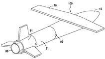
図1は、本発明による空中発射ランチャー100の一実施例の概略斜視図である。
この図では、ペイロード(この図には示さず)を保護するように設計された弾丸形状のノーズコーンに参照番号15が付してある。このノーズコーンは、必要な空力学的形状をランチャー100に提供する。
ノーズコーンの後側には段間スカート51が設けられており、これに続いて固体燃料段91が設けられている。固体燃料段91には、参照番号80を付した固体燃料ブロックが設けられている。
FIG. 1 is a schematic perspective view of one embodiment of an
In this figure, a bullet-shaped nose cone designed to protect the payload (not shown in this figure) is provided with
An
この図では、段間の取り付け部には参照番号90が付してある。
本発明によるバンドルは、ノーズコーン15及び段間スカート51によって覆われた第1段に設けられている。
図1の実施例では、本発明による空中発射ランチャー100は、翼70及びその後部の複数のテールフィンを含む。
In this figure, the
The bundle according to the present invention is provided in the first stage covered by the
In the embodiment of FIG. 1, an
図2は、ランチャー100の内部構造を概略に示す部分断面図である。
ノーズコーン15の下には、ペイロード60、例えば衛星が収容されている。
参照番号10は、強化フープ20によって互いに直接的に取り付けられた四つのタンクを含むバンドル全体に付してある。
強化フープ20は、図3の詳細図に示すように、タンクの一体の部分である。
図2でわかるように、バンドルの軸線は、空中発射ランチャー100の軸線と一致する。
FIG. 2 is a partial sectional view schematically showing the internal structure of the
Under the
The reinforced
As can be seen in FIG. 2, the axis of the bundle coincides with the axis of the
本発明によれば、ペイロード60は、エンジン50と同様にバンドルに直接的に取り付けられている。
本発明によれば、翼70はバンドル10に直接的に取り付けられている。
本明細書中に説明する例では、空中発射ランチャー100は、参照番号30を付した4個の高圧ヘリウム球を有する。これらの目的は、推進剤を放出することである。
According to the present invention, the
According to the present invention, the
In the example described herein, the
図3は、図2に示すランチャー100の長さ方向断面図であり、二つの細部を拡大して示す。これは、第1に、ペイロード60及びヘリウム球30をバンドル10に取り付ける方法を示すため、及び第2に、エンジン50をバンドル10に取り付ける方法を示すためである。
FIG. 3 is a longitudinal cross-sectional view of the
本明細書に説明した実施例では、スカート51は、実質的にフォーク形態の二叉部分を形成し、これにより、
・ノーズコーン15を分離するため、爆発性第1火工コードが設けられたファスナ90によってノーズコーン15に連結された外リング、及び
・図5に詳細に示す連結タブ80によって強化フープ20に連結された内リングを形成する。タブ80は、段間スカート51を分離するため、第1火工コードが設けられている。
In the embodiment described herein, the
• An outer ring connected to the
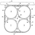
図4は、図3のIV−IV線での断面図である。この実施例では、第1断面75のケーシングは、隅部に丸味を付けた実質的に正方形断面である。この形状は、主断面をできるだけ小さくするのに役立つ。
本明細書中に説明したバンドル10は、参照番号11を付した一対の第1タンク及び参照番号12を付した一対の第2タンクを有する。
4 is a cross-sectional view taken along line IV-IV in FIG. In this embodiment, the casing of the
The
各対の両タンクには同じ推進剤が入っており、これらのタンクは、推進剤を同じ容積流量で送出する。
タンクは、強化フープ20を介して、参照番号25を付した継手によって互いに直接的に取り付けられている。
Both tanks in each pair contain the same propellant, and these tanks deliver propellant at the same volumetric flow rate.
The tanks are directly attached to one another via a reinforced
継手25は、二つのタンク間の距離を最小にするように構成されている。
ヘリウム球30は、強化フープ20にリンク31によって取り付けられている。
本明細書中に説明した例では、ペイロード60は支持プレート61に取り付けられており、この支持プレートは、シュラウドセクタ62によってタンク11及び12に連結されている。シュラウドセクタ62は、図4に示すように、強化フープ20に溶接されている。
The
The
In the example described herein,
本発明によれば、空中発射ランチャー100のインジェクション手段52は、四つのタンク11、12が全て同時に空になるようにエンジン50への供給を制御するようになっている。
本明細書中に説明した実施例では、エンジン50は、その推力の方向を変化する目的で操向可能である。
この目的のため、エンジン50は支持プレート53によって強化フープ20に連結されたユニバーサルブロック52に取り付けられている。エンジンが差し向けられる方向は、操向可能アクチュエータ54によって調節できる。
本明細書中に説明した実施例では、アクチュエータ54用の支持体は、継手55によって強化フープ20に取り付けられている。
According to the present invention, the injection means 52 of the
In the embodiments described herein, the
For this purpose, the
In the embodiment described herein, the support for the
本明細書中に説明した実施例では、翼70は、タンクに固定されたファスナ手段71によって、空中発射ランチャー100のタンク11、12に直接取り付けられている。
本明細書中に説明した実施例では、翼70は、更に詳細には、アイレット71を含み、これらのアイレット71がピン74によってマウンティング即ちフォーク72に連結される。これらのフォーク72自体は、強化フープ20に溶接されている。ピン74は、爆発性剪断ピンであり、これにより、翼70を投げ捨てる(jettison)ことができる。
In the embodiment described herein, the
In the embodiment described herein, the
100 空中発射ランチャー
10 バンドル
15 ノーズコーン
20 強化フープ
51 段間スカート
60 ペイロード
70 翼
80 固体燃料ブロック
91 固体燃料段
100
Claims (5)
各対は、同じ容積流量で流れるのに適した同じ密度の推進剤が入った二つのタンクを含み、
前記四つのタンクは、前記推進剤が流れているとき、前記対の各々の重心が常に前記バンドル(10)の軸線上にあり続けるように強化フープ(20)を介して互いに直接的に取り付けられている、ことを特徴とするバンドル。 In a bundle (10) comprising two pairs of cylindrical tanks ((11, 11), (12, 12)) of the same volume,
Each pair includes two tanks with the same density of propellant suitable to flow at the same volumetric flow rate,
The four tanks are directly attached to each other via a reinforcing hoop (20) so that when the propellant is flowing, the center of gravity of each of the pair always remains on the axis of the bundle (10). A bundle characterized by that.
前記強化フープ(20)は、前記タンク(11、12)の一体の部分を形成する、ことを特徴とするバンドル。 Bundle (10) according to claim 1,
The bundle characterized in that the reinforcing hoop (20) forms an integral part of the tank (11, 12).
前記強化フープ(20)のうちの少なくとも幾つかが、エンジン(50)用及びペイロード(60)用のファスナ手段(25、73)を含む、ことを特徴とするバンドル。 In the bundle according to claim 1 or 2,
Bundle, characterized in that at least some of the reinforcing hoops (20) comprise fastener means (25, 73) for the engine (50) and the payload (60).
請求項1、2、又は3に記載のタンクのバンドル(10)を含み、
前記タンク(11、12)のうちの二つに固定されたファスナ手段(71)を含み、これにより、前記ランチャー(100)の翼(70)を前記タンクに直接的に取り付けることができる、ことを特徴とする空中発射ランチャー。 In the air launcher (100),
A bundle of tanks (10) according to claim 1, 2 or 3,
Including fastener means (71) fixed to two of the tanks (11, 12), so that the wings (70) of the launcher (100) can be directly attached to the tank; An aerial launcher featuring
前記バンドル(10)が設けられた第1段(75)の断面は、隅部に丸味を付けた正方形形状の断面である、ことを特徴とする空中発射ランチャー。 The aerial launcher according to claim 4,
The air launch launcher according to claim 1, wherein a cross section of the first stage (75) provided with the bundle (10) is a square cross section with rounded corners.
Applications Claiming Priority (2)
| Application Number | Priority Date | Filing Date | Title |
|---|---|---|---|
| FR0856002 | 2008-09-08 | ||
| FR0856002A FR2935686B1 (en) | 2008-09-08 | 2008-09-08 | FAGOT HAVING TWO PAIRS OF RESERVOIRS AND AIRBORNE LAUNCHER COMPRISING SUCH A FAGOT |
Publications (2)
| Publication Number | Publication Date |
|---|---|
| JP2010064735A true JP2010064735A (en) | 2010-03-25 |
| JP5566643B2 JP5566643B2 (en) | 2014-08-06 |
Family
ID=40651694
Family Applications (1)
| Application Number | Title | Priority Date | Filing Date |
|---|---|---|---|
| JP2009202304A Expired - Fee Related JP5566643B2 (en) | 2008-09-08 | 2009-09-02 | A bundle containing two pairs of tanks and an air launch launcher containing such a bundle |
Country Status (7)
| Country | Link |
|---|---|
| US (1) | US8226045B2 (en) |
| EP (1) | EP2161198B1 (en) |
| JP (1) | JP5566643B2 (en) |
| CN (1) | CN101670888B (en) |
| FR (1) | FR2935686B1 (en) |
| RU (1) | RU2509039C2 (en) |
| UA (1) | UA102064C2 (en) |
Cited By (1)
| Publication number | Priority date | Publication date | Assignee | Title |
|---|---|---|---|---|
| JP2016524092A (en) * | 2013-07-08 | 2016-08-12 | エアバス ディフェンス アンド スペース エスアーエス | Propulsion unit for reusable launch vehicle |
Families Citing this family (4)
| Publication number | Priority date | Publication date | Assignee | Title |
|---|---|---|---|---|
| FR2980177B1 (en) * | 2011-09-20 | 2014-07-11 | Centre Nat Etd Spatiales | PROPULSIVE BAY |
| US20140077506A1 (en) * | 2012-09-14 | 2014-03-20 | Kohler Co. | Modular configuration for an lp towable genset |
| DE102018129898B4 (en) * | 2018-11-27 | 2021-02-04 | Airbus Defence and Space GmbH | Device for carrying fuel in an aircraft and spacecraft |
| CN110155371B (en) * | 2019-06-03 | 2021-06-01 | 北京航空航天大学 | Inflatable jet take-off and gliding recovery mars aircraft and use method thereof |
Citations (2)
| Publication number | Priority date | Publication date | Assignee | Title |
|---|---|---|---|---|
| US5816539A (en) * | 1994-02-18 | 1998-10-06 | Lockheed Martin Corporation | Orbital assist module and interstage |
| JP2003291899A (en) * | 2002-04-01 | 2003-10-15 | Mitsubishi Electric Corp | Artificial satellite structure |
Family Cites Families (10)
| Publication number | Priority date | Publication date | Assignee | Title |
|---|---|---|---|---|
| US3180084A (en) * | 1961-02-13 | 1965-04-27 | Ciary Corp | Thrust device |
| US3243150A (en) * | 1964-04-09 | 1966-03-29 | Boeing Co | Aerospace vehicle and tank structure |
| US3286629A (en) * | 1964-10-07 | 1966-11-22 | Jay H Laue | Multi-mission module |
| US4699339A (en) * | 1985-03-01 | 1987-10-13 | Hughes Aircraft Company | Apparatus and method for transporting a spacecraft and a fluid propellant from the earth to a substantially low gravity environment above the earth |
| US4741502A (en) * | 1985-10-01 | 1988-05-03 | Hughes Aircraft Company | Method and apparatus for launching a spacecraft by use of a recoverable upper rocket stage |
| RU2059858C1 (en) * | 1993-09-14 | 1996-05-10 | Конструкторское бюро "Арсенал" им.М.В.Фрунзе | Compartment of liquid rocket engine for spacecraft |
| US5533331A (en) * | 1994-05-25 | 1996-07-09 | Kaiser Marquardt, Inc. | Safe propulsion system for missile divert thrusters and attitude control thrusters and method for use of same |
| RU2094333C1 (en) * | 1995-01-12 | 1997-10-27 | Научно-производственное объединение им.С.А.Лавочкина | Rocket-propelled flying vehicle (versions) and rocket engine |
| US6412274B1 (en) * | 2000-06-02 | 2002-07-02 | Bwx Technologies, Inc. | Solar thermal rocket |
| RU2309092C2 (en) * | 2006-01-12 | 2007-10-27 | Федеральное государственное унитарное предприятие "Центральный научно-исследовательский институт машиностроения" (ФГУП ЦНИИмаш) | Orbital filling module |
-
2008
- 2008-09-08 FR FR0856002A patent/FR2935686B1/en not_active Expired - Fee Related
-
2009
- 2009-08-24 US US12/546,252 patent/US8226045B2/en not_active Expired - Fee Related
- 2009-08-26 EP EP09168706.1A patent/EP2161198B1/en not_active Not-in-force
- 2009-09-01 CN CN200910170648.2A patent/CN101670888B/en not_active Expired - Fee Related
- 2009-09-02 JP JP2009202304A patent/JP5566643B2/en not_active Expired - Fee Related
- 2009-09-07 RU RU2009133242/11A patent/RU2509039C2/en not_active IP Right Cessation
- 2009-09-07 UA UAA200909208A patent/UA102064C2/en unknown
Patent Citations (2)
| Publication number | Priority date | Publication date | Assignee | Title |
|---|---|---|---|---|
| US5816539A (en) * | 1994-02-18 | 1998-10-06 | Lockheed Martin Corporation | Orbital assist module and interstage |
| JP2003291899A (en) * | 2002-04-01 | 2003-10-15 | Mitsubishi Electric Corp | Artificial satellite structure |
Cited By (1)
| Publication number | Priority date | Publication date | Assignee | Title |
|---|---|---|---|---|
| JP2016524092A (en) * | 2013-07-08 | 2016-08-12 | エアバス ディフェンス アンド スペース エスアーエス | Propulsion unit for reusable launch vehicle |
Also Published As
| Publication number | Publication date |
|---|---|
| RU2009133242A (en) | 2011-03-20 |
| RU2509039C2 (en) | 2014-03-10 |
| US20100059630A1 (en) | 2010-03-11 |
| CN101670888B (en) | 2015-04-29 |
| FR2935686B1 (en) | 2010-09-24 |
| CN101670888A (en) | 2010-03-17 |
| EP2161198B1 (en) | 2014-02-19 |
| US8226045B2 (en) | 2012-07-24 |
| FR2935686A1 (en) | 2010-03-12 |
| EP2161198A1 (en) | 2010-03-10 |
| JP5566643B2 (en) | 2014-08-06 |
| UA102064C2 (en) | 2013-06-10 |
Similar Documents
| Publication | Publication Date | Title |
|---|---|---|
| JP5566643B2 (en) | A bundle containing two pairs of tanks and an air launch launcher containing such a bundle | |
| US8955791B2 (en) | First and second stage aircraft coupled in tandem | |
| US5529264A (en) | Launch vehicle system | |
| CN108177798A (en) | For disposing the system and method for spacecraft | |
| US9745063B2 (en) | Airborne rocket launch system | |
| KR20210082553A (en) | Heat exchanger | |
| JP2011502845A (en) | Modular spacecraft | |
| US5245927A (en) | Dual-tandem unmanned air vehicle system | |
| AU2018288789A1 (en) | Systems and techniques for launching a payload | |
| US6817580B2 (en) | System and method for return and landing of launch vehicle booster stage | |
| US3202381A (en) | Recoverable rocket vehicle | |
| US20230418308A1 (en) | Monolithic attitude control motor frame and system | |
| US8800934B1 (en) | Space access system with reusable booster | |
| US9403605B2 (en) | Multiple stage tractor propulsion vehicle | |
| JP5417040B2 (en) | Sliding fairing decapitation device and sliding fairing decapitation method | |
| US10254094B1 (en) | Aircraft shroud system | |
| US8002219B2 (en) | Multi-functional annular fairing for coupling launch abort motor to space vehicle | |
| EP2917683B1 (en) | Rocket propelled payload with divert control system within nose cone | |
| KR100998138B1 (en) | Payload launching system | |
| Doran et al. | Status update report for the Peregrine sounding rocket project: Part III | |
| JP6639676B2 (en) | Lightweight spacecraft dispenser | |
| Pitot de la Beaujardiere et al. | The phoenix hybrid sounding rocket program: a progress report | |
| JP5634785B2 (en) | Flying object | |
| JP2001095447A (en) | Fishing tackle | |
| US9352854B2 (en) | Space flight drive and flight craft |
Legal Events
| Date | Code | Title | Description |
|---|---|---|---|
| A621 | Written request for application examination |
Free format text: JAPANESE INTERMEDIATE CODE: A621 Effective date: 20120712 |
|
| A131 | Notification of reasons for refusal |
Free format text: JAPANESE INTERMEDIATE CODE: A131 Effective date: 20130722 |
|
| A601 | Written request for extension of time |
Free format text: JAPANESE INTERMEDIATE CODE: A601 Effective date: 20131017 |
|
| A602 | Written permission of extension of time |
Free format text: JAPANESE INTERMEDIATE CODE: A602 Effective date: 20131022 |
|
| A521 | Request for written amendment filed |
Free format text: JAPANESE INTERMEDIATE CODE: A523 Effective date: 20131224 |
|
| TRDD | Decision of grant or rejection written | ||
| A01 | Written decision to grant a patent or to grant a registration (utility model) |
Free format text: JAPANESE INTERMEDIATE CODE: A01 Effective date: 20140519 |
|
| A61 | First payment of annual fees (during grant procedure) |
Free format text: JAPANESE INTERMEDIATE CODE: A61 Effective date: 20140618 |
|
| R150 | Certificate of patent or registration of utility model |
Ref document number: 5566643 Country of ref document: JP Free format text: JAPANESE INTERMEDIATE CODE: R150 |
|
| R250 | Receipt of annual fees |
Free format text: JAPANESE INTERMEDIATE CODE: R250 |
|
| S111 | Request for change of ownership or part of ownership |
Free format text: JAPANESE INTERMEDIATE CODE: R313113 |
|
| S533 | Written request for registration of change of name |
Free format text: JAPANESE INTERMEDIATE CODE: R313533 |
|
| R350 | Written notification of registration of transfer |
Free format text: JAPANESE INTERMEDIATE CODE: R350 |
|
| R250 | Receipt of annual fees |
Free format text: JAPANESE INTERMEDIATE CODE: R250 |
|
| LAPS | Cancellation because of no payment of annual fees |