JP2010063820A - Chair - Google Patents
Chair Download PDFInfo
- Publication number
- JP2010063820A JP2010063820A JP2008235566A JP2008235566A JP2010063820A JP 2010063820 A JP2010063820 A JP 2010063820A JP 2008235566 A JP2008235566 A JP 2008235566A JP 2008235566 A JP2008235566 A JP 2008235566A JP 2010063820 A JP2010063820 A JP 2010063820A
- Authority
- JP
- Japan
- Prior art keywords
- lumbar support
- back plate
- front surface
- guide member
- chair
- Prior art date
- Legal status (The legal status is an assumption and is not a legal conclusion. Google has not performed a legal analysis and makes no representation as to the accuracy of the status listed.)
- Granted
Links
Images


Abstract
Description
本発明は、着座者の腰部をサポートすべくランバーサポートを設けた椅子に関する。 The present invention relates to a chair provided with a lumbar support so as to support a waist of a seated person.
従来、着座者の腰部をサポートすべく構成された椅子が種々知られている。このような椅子の一例として、例えば、背凭れを弾性材製の芯材を備えるものとし、この背凭れの下端部を昇降させることにより前記芯材が弾性変形し、着座者の腰部をサポートするランバーサポート部として機能する部分が前後及び上下方向に向かって突没するように構成しているものが考えられている(例えば、特許文献1を参照)。
ところで、特許文献1記載の構成の椅子においては、確かにランバーサポート部として機能する部分が前後及び上下方向に向かって突没させうるように構成しているものの、このランバーサポート部は上下方向位置にかかわらず正面に向かって突出している。 By the way, in the chair of composition of patent documents 1, although the part which functions as a lumbar support part is certainly constituted so that it can project and sink toward the front and back and the up-and-down direction, this lumbar support part is an up-and-down direction position. Regardless of whether it protrudes toward the front.
一方、着座姿勢等によっては、ランバーサポート部が正面に向かって突出させた状態では必ずしも着座者の腰部を好適にサポートできない場合があり、ランバーサポート部の突出方向を変更可能にする要望が存在する。このような要望は、特に背凭れが後傾可能である椅子において顕著である。しかし、上述したように、前記特許文献1に記載の構成では、このような要望に対応することが困難である。 On the other hand, depending on the sitting posture and the like, the lumbar support part may not necessarily support the waist of the seated person in a state where the lumbar support part protrudes toward the front, and there is a desire to be able to change the protruding direction of the lumbar support part. . Such a demand is particularly remarkable in a chair in which the backrest can be tilted backward. However, as described above, with the configuration described in Patent Document 1, it is difficult to meet such a demand.
本発明はこのような課題を解決すること、背凭れを後傾させた際等、着座姿勢を変更した際であっても、所望の姿勢でランバーサポートにより着座者の腰部を支持できるようにすることを目的とする。 The present invention solves such a problem, and enables the lumbar support to support the waist of the seated person in a desired posture even when the seating posture is changed, such as when the backrest is tilted backward. For the purpose.
すなわち本発明に係る椅子は、背板の前面にランバーサポートを着脱可能に装着することができるようにした椅子であって、前記ランバーサポートが、着座者の腰部をサポートするためのランバーサポート本体と、前記背板の前面に着脱可能に装着され前記ランバーサポート本体をその向きが背板の前面の向きに同調しつつ上下移動し得るように案内する上下案内部材とを備えたものであり、前記上下案内部材が、背板の前面が最も前方に突出している迫出部分を含みその上下に亘って装着されることを特徴とする。 That is, the chair according to the present invention is a chair that can detachably attach a lumbar support to the front surface of the back plate, and the lumbar support includes a lumbar support main body for supporting a lumbar part of a seated person, An upper and lower guide member that is detachably attached to the front surface of the back plate and guides the lumbar support main body so that the lumbar support body can move up and down in synchronization with the direction of the front surface of the back plate, The vertical guide member is mounted over the top and bottom of the back plate, including a protruding portion where the front surface of the back plate protrudes most forward.
このようなものであれば、ランバーサポート本体を上下移動させることにより、該ランバーサポート本体に、正面向き姿勢だけでなく、上向き姿勢及び下向き姿勢のいずれをも採らせることが可能になる。 In such a case, by moving the lumbar support main body up and down, it is possible for the lumbar support main body to adopt not only a front-facing posture but also an upward posture and a downward posture.
このような椅子において、着座者の腰部をより好適にサポートさせるべく、ランバーサポートの取付位置を変更可能にするためには、前記背板が少なくとも前記迫出部分付近に複数の孔を有したものであり、前記上下案内部材が、前記孔のいずれかを選択的に利用して前記背板に装着されるものが望ましい。 In such a chair, in order to make it possible to change the mounting position of the lumbar support in order to more suitably support the waist of the seated person, the back plate has a plurality of holes at least near the protruding portion. Preferably, the upper and lower guide members are attached to the back plate selectively using any of the holes.
特に、前記上下案内部材が、前記背板の前面に添接し得る程度の可撓性を備えたものであれば、このような上下案内部材の取付位置に関わらず該上下案内部材を前記背板の前面に添接させることができる。 In particular, if the vertical guide member is flexible enough to contact the front surface of the back plate, the vertical guide member is attached to the back plate regardless of the mounting position of the vertical guide member. It can be attached to the front of the.
このような上下案内部材の取付態様を好適に実現可能な背板の構成の一例として、前記背板が、メッシュ領域と、孔を有しないシェル領域とを備えたものであり、前記孔が前記メッシュ領域を形成するためのものが挙げられる。 As an example of the configuration of a back plate that can suitably realize such an attachment mode of the vertical guide member, the back plate includes a mesh region and a shell region having no hole, and the hole is the For forming a mesh region.
特に、前記シェル領域が水平なベルト状をなすものであり、前記迫出部分にバンド状をなすシェル領域を配するとともに、シェル領域の上下にそれぞれメッシュ領域を配しているものであれば、前記迫出部分にシェル領域を配しているので、着座者の荷重を前記シェル領域で受けることとなり、着座者にランバーサポートによる保持感を与えることができる。 In particular, if the shell region is a horizontal belt, and a shell region that forms a band in the protruding portion, and mesh regions above and below the shell region, respectively, Since the shell region is arranged at the protruding portion, the load of the seated person is received by the shell region, and the seated person can be given a feeling of holding by the lumbar support.
本発明に係る椅子の構成によれば、背板の前面が最も前方に突出している迫出部分を含みその上下に亘って装着される上下案内部材に案内させつつランバーサポート本体を上下移動させることにより、該ランバーサポート本体に上向き姿勢、正面向き姿勢及び下向き姿勢のいずれをも採らせることができる。従って、背凭れを後傾させた際等、着座姿勢を変更した際であっても、着座者の所望の姿勢でランバーサポートにより着座者の腰部を支持させることができる。 According to the configuration of the chair according to the present invention, the lumbar support main body is moved up and down while being guided by the vertical guide member that is mounted on the top and bottom of the back plate including the protruding portion where the front surface of the back plate protrudes most forward. Thus, the lumbar support main body can take any of the upward posture, the front-facing posture, and the downward posture. Therefore, even when the seating posture is changed, such as when the backrest is tilted backward, the seated person's waist can be supported by the lumbar support in the seater's desired posture.
以下、本発明をシンクロチルト式の事務用回転椅子100に適用した場合の一実施形態につき、図面を参照して説明する。
Hereinafter, an embodiment in which the present invention is applied to a synchro tilt type
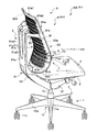
この椅子100は、図1〜図3に示すように、脚1と、この脚1の上部に支持され水平旋回可能な支持基部2と、この支持基部2の上に配された座受3と、この座受3に保持された座4と、前記支持基部2に後傾動作可能に設けられた背支持体5と、この背支持体5に取り付けられた背凭れ6とを具備してなる。
As shown in FIGS. 1 to 3, the
前記脚1は、脚ベース11と、脚ベース11の中心部に設けられた脚支柱12とを備えてなる。前記脚ベース11は、中心部に設けたハブ11aから脚羽根11bを放射状に突出させて設けたもので、前記脚羽根11b先端にキャスター11cをそれぞれ設けている。前記脚支柱12は、ガススプリングを主体に構成されたもので、上下方向に弾性的に伸縮し、所望位置でロックすることができるようにした通常のものである。
The leg 1 includes a
前記支持基部2は、前記脚支柱12の上端部に取り付けられたハウジング21と、このハウジング21に剛結され前記背支持体5を後傾動作可能に支持する主軸22と、前記ハウジング21内に設けられ前記背支持体5の後傾動作に対して反発力を発生させる図示しない傾動反力発生機構とを具備してなる。前記傾動反力発生機構は、コイルスプリングやガススプリング等を用いた通常のものであるため、説明を省略する。
The
前記座受3は、前記座4を保持するシェル状のもので、その前端側が前記支持基部2に前後動可能に取り付けられているとともに、その後端側が前記背支持体5の基端部に支持されている。
The
前記背支持体5は、前記支持基部2の主軸22に後傾動作可能に支持された背支桿51と、この背支桿51の上端部に取り付けられた弾性横桿52とを具備してなる。前記背支桿51は、基端部を前記支持基部2に取り付けた下部背フレーム51bと、この下部背フレーム51bの先端に結合した上部背フレーム51aとを備えている。前記下部背フレーム51bは、金属製のもので、その外側がカバー53により覆われている。そのカバー53の外面は、前記上部背フレーム51aの外面に連続するように位置づけられている。前記上部背フレーム51aは、合成樹脂により一体成形されたもので、その上部を二股に分岐させて分岐桿部51a2を形成している。この分岐桿部51a2は、略直線状に起立している。前記弾性横桿52は、中間部二箇所を前記背支桿51の上端部、さらに具体的には各分岐桿部51a2の上端部に枢軸たる図示しない取付軸を介して支持させた板ばね状のもので、その両端部で前記背凭れ6を支えている。
The
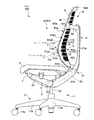
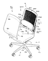
前記背凭れ6は、背板61を主体に構成されたものである。前記背板61は、背板本体61aとこの背板本体61aの左右両側部に設けた側端取付部61cと、前記背板本体61aの下端部に設けた下端取付部61bとを具備してなるもので、前記側端取付部61cを前記弾性横桿52の両端部に接続するとともに、前記下端取付部61bを前記背支桿51の下部背フレーム51bに取り付けている。前記背板本体61aは、合成樹脂により作られたもので、孔61dを有しない周縁枠部61a1と、この周縁枠部61a1に囲まれた中間面部61a2とを具備してなる。前記中間面部61a2は、複数の孔61dを設けた樹脂メッシュ領域Mと、孔61dを有しない樹脂シェル領域Sとを備えたもので、その樹脂メッシュ領域Mと樹脂シェル領域Sとを交互に配置している。具体的には、前記中間面部61a2の樹脂シェル領域Sは、水平なベルト状のもので前記周縁枠部61a1の対向部位を連結するように配されている。ベルト状をなす前記樹脂シェル領域Sは、上下方向に間隔を開けて複数本平行に配されており、これら樹脂シェル領域S間及び樹脂シェル領域Sと周縁枠部61a1との間に前記樹脂メッシュ領域Mがそれぞれ形成されている。前記樹脂メッシュ領域Mは、前記樹脂シェル領域Sよりも薄肉に形成されており、多数の孔61dを有している。前記樹脂シェル領域Sの前面と前記樹脂メッシュ領域Mの前面とは面一に形成されている。また、前記樹脂メッシュ領域Mの背面は、前記樹脂シェル領域Sの背面よりも凹んで設けられている。一方、前記周縁枠部61a1の前面と前記中間面部61a2との境界には、段部61a3が形成されている。換言すれば、前記段部61a3を境にして、前記中間面部61a2が前記周縁枠部61a1よりも前方にせり出すような形態をなしている。ここで、本実施形態では、背板61の前面が最も前方に突出している部位である迫出部分61xに、バンド状をなす樹脂シェル領域Sを配している。また、本実施形態では、この背板61の前方に外装材62を取り付け可能にしている。この外装材62は、背凭れ6の前面を形成する張地及びこの張地と背板との間に配されるクッションを有する外装材本体62aと、この外装材62を背板61の係止縁部すなわち上縁部に係わり合わせるための上縁取付部62bと、この外装材を背板の下縁部に係わり合わせるための下縁取付部62cとを具備する。なお、図1及び図2中では、この外装材62は想像線で示している。また、図3には、この外装材62を取り外した状態の斜視図を示している。
The
しかして、この椅子は、前記図3、及び図4〜図8に示すように、前記背板61の前面にランバーサポート7を着脱可能に装着可能である。
As shown in FIGS. 3 and 4 to 8, the
このランバーサポート7は、分解斜視図である図4に示すように、また、このランバーサポート7の取付部位の横断面図である図5に示すように、着座者の腰部をサポートするためのランバーサポート本体71と、前記背板6の前面に着脱可能に装着され前記ランバーサポート本体71をその向きが背板61の前面の向きに同調しつつ上下移動し得るように案内する上下案内部材72とを具備する。
As shown in FIG. 4 which is an exploded perspective view of the
具体的には、前記ランバーサポート本体71は、インナープレート71aと、このインナープレート71aの前面に装着したサポートパッド71bとを具備する。前記インナープレート71aには、その左右両端部に、前記背凭れ6の外装材62の左右両側端より外側に延伸する取手71a1を設けている。そして、これら左右の取手71a1間の部位の前方に前記サポートパッド71bを取り付けるようにしている。
Specifically, the lumbar support
一方、前記上下案内部材72は、背板61の前面が最も前方に突出している迫出部分61xを含みその上下に亘って装着される左右1対の部材である。この上下案内部材72は、背板61の孔61dのいずれかを選択的に利用して前記背板61に装着するようにしている。さらに、前記上下案内部材72は、前記背板61の前面に添接し得る程度の可撓性を備えた例えば樹脂製の部材である。
On the other hand, the upper and
より具体的には、この上下案内部材72は、背板61の前面から前方に突出する起立部72aと、この起立部72aの突出端から背板61の幅方向中央に向かう側と反対側に延伸する抜止爪部72bとを具備する。また、この上下案内部材72の起立部72aの背面には雌ねじ穴72a1を上下に離間させて複数箇所、具体的には2箇所に設けている。そして、この上下案内部材72を背凭れ6の前面に沿った形状にした状態で、前記雌ねじ穴72a1と背板61の孔61dとを重合させ、背板61の後方から取付具たる雄ねじ部材72cを前記雌ねじ孔72a1にねじ止めすることによりこの上下案内部材72を背板61に取り付けるようにしている。ここで、本実施形態では、前記背板61の背面と雄ねじ部材72cの頭部との間に、前記雄ねじ部材72dを挿し通すためのねじ通過孔72d1を有する台座72dを配している。
More specifically, the
一方、前記ランバーサポート本体71は、その背面、より具体的には前記インナープレート71aの背面に、前記上下案内部材72に係り合い左右に対をなして設けた被案内爪部71cを具備する。この被案内爪部71cは、ランバーサポート本体71の背面から後方に突出する起立部71c1と、この起立部71c1の突出端からランバーサポート71の幅方向中央に向かう側に延伸する抜止部71c2とを具備する。そして、この被案内爪部71cの抜止部71c2が前記上下案内部材72の抜止爪部72bに係り合うことにより、ランバーサポート本体71が前記上下案内部材72を介して背板61に上下移動可能に保持される。なお、本実施形態では、この被案内爪部71cは、上下方向に離間させて複数対、具体的には2対設けている。
On the other hand, the lumbar support
このランバーサポート7は、以下のようにして背板61に取り付けられる。
The
まず、上下案内部材72を、図4に示すように、背板61の前面の前記迫出部分61xを挟んで上下に跨る部位に沿わせて配置する。次いで、この上下案内部材72の背面の全体が背板61の前面に略又は完全に接触するように上下案内部材72を変形させる。それから、この上下案内部材72の雌ねじ孔72a1と、背板61の孔61dのいずれかと、台座72dのねじ通過孔72d1とを重合させ、雄ねじ部材72cを背板61の後方から前記雌ねじ孔72a1にねじ止めすることによりこの上下案内部材72を背板61の前面に取り付ける。そして、この上下案内部材72の抜止爪部72bと前記ランバーサポート本体71背面の被案内爪部71cの抜止部71c2とを係わり合わせる。すなわち、前記上下案内部材72の抜止爪部72bと背板61の前面との間に前記ランバーサポート本体71の被案内爪部71cの抜止部71c2を位置させる。
First, as shown in FIG. 4, the
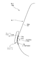
このランバーサポート本体71の上下位置の変更は、前記取手71a1を把持した状態でランバーサポート本体71を上下移動させることにより行う。その際、前記ランバーサポート本体71を左右に移動しようとすると、前記被案内爪部71cの抜止部71c2が前記上下案内部材72に衝き当たるので、このランバーサポート本体71の左右位置への移動が規制され、ランバーサポート本体71の移動方向が案内される。すなわち、背板61及びランバーサポート7を概略的に示した図6において、ランバーサポート本体71は、矢印X方向又は矢印Y方向に移動可能である。
The vertical position of the lumbar support
ここで、上述したように、前記ランバーサポート本体71の向きは、この背板61の前面の向きに同調して変化する。すなわち、このランバーサポート本体71の高さ位置と背板61の前記迫出部分61xの高さ位置とが一致している場合には、前記図6に示すように、ランバーサポート7は正面を向く。その際、上述したように、前記迫出部分61xには前記樹脂シェル領域Sを配しているので、ランバーサポート本体71はこの樹脂シェル領域Sに支持される。すなわち、着座者からの荷重はこのランバーサポート本体71を介して背板61の樹脂シェル領域Sが受けるようにしている。一方、このランバーサポート本体71が背板61の前記迫出部分61xより上方に位置する場合には、図7に示すように、ランバーサポート7は上向きである。そして、このランバーサポート本体71が背板61の前記迫出部分61xより下方に位置する場合には、図8に示すように、ランバーサポート7は下向きである。
Here, as described above, the orientation of the lumbar support
以上に述べたように、本実施形態に係る椅子100の構成によれば、ランバーサポート7が、背板61の前面に着脱可能に装着されランバーサポート本体71をその向きが背板61の前面の向きに同調しつつ上下移動し得るように案内する上下案内部材72を備えているとともに、この上下案内部材72を、背板61の前面が最も前方に突出している迫出部分61xを含みその上下に亘って装着しているので、ランバーサポート本体71を上下移動させることにより、該ランバーサポート本体71に、前記図7に示すような上向き姿勢、前記図6に示すような正面向き姿勢、及び前記図8に示すような下向き姿勢のいずれをも採らせることが可能になる。すなわち、このような椅子100の背凭れ6を後傾させた場合等、着座姿勢を変更した場合であっても、着座者の所望の姿勢でランバーサポート7に着座者の腰部を支持させることができる。
As described above, according to the configuration of the
また、前記背板61が迫出部分61x付近に複数の孔61dを有しているとともに、前記上下案内部材72を、前記孔61dのいずれかを選択的に利用して前記背板61に装着するようにしているので、着座者の腰部をより好適にサポートさせるべく、ランバーサポート7の取付位置を変更可能にすることができる。
Further, the
さらに、前記上下案内部材72が、前記背板61の前面に添接し得る程度の可撓性を備えているので、このような上下案内部材72の取付位置に関わらず該上下案内部材72を前記背板61の前面に添接させることができる。
Further, since the
また、前記背板61が、前記孔61dを多数形成してなる樹脂メッシュ領域Mと、孔61dを有しないシェル領域Sとを備えたものであるので、広く知られているこのような背板61に大幅な設計変更を加えることなく、上下案内部材72の取付態様を好適に実現可能である。
Further, since the
そして、前記樹脂シェル領域Sが水平なベルト状をなすものであり、前記迫出部分61xにバンド状をなす樹脂シェル領域Sを配しているとともに、この樹脂シェル領域Sの上下にそれぞれ樹脂メッシュ領域Mを配しているので、上述したように着座者の荷重を前記樹脂シェル領域Sで受けることとなり、着座者にランバーサポート7による保持感を与えることができる。
The resin shell region S has a horizontal belt shape, and a band-shaped resin shell region S is disposed on the protruding
なお、本発明は以上に述べた実施形態に限られない。 The present invention is not limited to the embodiment described above.
例えば、上述した実施形態では、上下案内部材は背板の樹脂メッシュ領域に設けた孔を利用して取り付けるようにしているが、メッシュ孔を有しない背板に、上下案内部材を取り付けるための孔を設け、この孔を利用して上下案内部材を取り付けるようにしてもよい。また、木製等板状の背板の後方から木ねじ等を利用して上下案内部材を背板に接続してもよい。この場合、迫出部分を含みその上下にわたって上下案内部材を装着すれば本発明の最も主要な効果は得ることができるので、必ずしも上下位置は変更可能でなくともよい。ここで、上下案内部材の上下位置が変更可能でない場合、上下案内部材が可撓性を備えるものである必要はない。 For example, in the above-described embodiment, the upper and lower guide members are attached using holes provided in the resin mesh region of the back plate, but the holes for attaching the upper and lower guide members to the back plate having no mesh hole. And the vertical guide member may be attached using this hole. Moreover, you may connect an up-and-down guide member to a back board using a wood screw etc. from the back of plate-like back boards, such as a wooden board. In this case, the most significant effect of the present invention can be obtained if the vertical guide member is attached to the upper and lower sides including the protruding portion, and therefore the vertical position may not necessarily be changeable. Here, when the vertical position of the vertical guide member is not changeable, the vertical guide member does not have to be flexible.
加えて、上述した実施形態では、背板が、水平なバンド状をなすシェル領域と、このシェル領域の上下に配したメッシュ領域とを有する構成を採用しているが、シェル領域及びメッシュ領域の形状はこのようなものに限らず、例えばシェル領域が垂直なものや、傾斜を有するものを採用してもよく、また、複数の円形のメッシュ領域を配置するとともに、残りの部分をシェル領域とする構成を採用してもよい。 In addition, in the above-described embodiment, the back plate adopts a configuration having a shell region having a horizontal band shape and a mesh region arranged above and below the shell region. The shape is not limited to this. For example, the shell region may be vertical or inclined, and a plurality of circular mesh regions may be arranged, and the remaining portion may be defined as the shell region. You may employ | adopt the structure to do.
その他、本発明の趣旨を損ねない範囲で種々に変更してよい。 In addition, various changes may be made without departing from the spirit of the present invention.
100…椅子
61…背板
61x…迫出部分
7…ランバーサポート
71…ランバーサポート本体
72…上下案内部材
DESCRIPTION OF
Claims (5)
Priority Applications (1)
| Application Number | Priority Date | Filing Date | Title |
|---|---|---|---|
| JP2008235566A JP5453632B2 (en) | 2008-09-12 | 2008-09-12 | Chair |
Applications Claiming Priority (1)
| Application Number | Priority Date | Filing Date | Title |
|---|---|---|---|
| JP2008235566A JP5453632B2 (en) | 2008-09-12 | 2008-09-12 | Chair |
Publications (2)
| Publication Number | Publication Date |
|---|---|
| JP2010063820A true JP2010063820A (en) | 2010-03-25 |
| JP5453632B2 JP5453632B2 (en) | 2014-03-26 |
Family
ID=42189932
Family Applications (1)
| Application Number | Title | Priority Date | Filing Date |
|---|---|---|---|
| JP2008235566A Expired - Fee Related JP5453632B2 (en) | 2008-09-12 | 2008-09-12 | Chair |
Country Status (1)
| Country | Link |
|---|---|
| JP (1) | JP5453632B2 (en) |
Cited By (3)
| Publication number | Priority date | Publication date | Assignee | Title |
|---|---|---|---|---|
| WO2013065816A1 (en) | 2011-11-04 | 2013-05-10 | 株式会社岡村製作所 | Chair |
| JP2013094579A (en) * | 2011-11-04 | 2013-05-20 | Okamura Corp | Chair |
| JP2020089693A (en) * | 2018-12-03 | 2020-06-11 | 国誉家具(中国)有限公司 | Chair |
Citations (5)
| Publication number | Priority date | Publication date | Assignee | Title |
|---|---|---|---|---|
| JP2001128787A (en) * | 1999-11-08 | 2001-05-15 | Okamura Corp | Lumber-supporting device of chair |
| JP2002191462A (en) * | 2000-12-27 | 2002-07-09 | Okamura Corp | Lumber support device for chair |
| JP2003284616A (en) * | 2002-03-27 | 2003-10-07 | Kokuyo Co Ltd | Chair |
| JP2004049657A (en) * | 2002-07-22 | 2004-02-19 | Okamura Corp | Backrest device of chair |
| JP2008000364A (en) * | 2006-06-22 | 2008-01-10 | Okamura Corp | Lumbar support device of chair |
-
2008
- 2008-09-12 JP JP2008235566A patent/JP5453632B2/en not_active Expired - Fee Related
Patent Citations (5)
| Publication number | Priority date | Publication date | Assignee | Title |
|---|---|---|---|---|
| JP2001128787A (en) * | 1999-11-08 | 2001-05-15 | Okamura Corp | Lumber-supporting device of chair |
| JP2002191462A (en) * | 2000-12-27 | 2002-07-09 | Okamura Corp | Lumber support device for chair |
| JP2003284616A (en) * | 2002-03-27 | 2003-10-07 | Kokuyo Co Ltd | Chair |
| JP2004049657A (en) * | 2002-07-22 | 2004-02-19 | Okamura Corp | Backrest device of chair |
| JP2008000364A (en) * | 2006-06-22 | 2008-01-10 | Okamura Corp | Lumbar support device of chair |
Cited By (4)
| Publication number | Priority date | Publication date | Assignee | Title |
|---|---|---|---|---|
| WO2013065816A1 (en) | 2011-11-04 | 2013-05-10 | 株式会社岡村製作所 | Chair |
| JP2013094579A (en) * | 2011-11-04 | 2013-05-20 | Okamura Corp | Chair |
| US9155393B2 (en) | 2011-11-04 | 2015-10-13 | Okamura Corporation | Chair |
| JP2020089693A (en) * | 2018-12-03 | 2020-06-11 | 国誉家具(中国)有限公司 | Chair |
Also Published As
| Publication number | Publication date |
|---|---|
| JP5453632B2 (en) | 2014-03-26 |
Similar Documents
| Publication | Publication Date | Title |
|---|---|---|
| JP5386728B2 (en) | Chair | |
| JP2011103933A (en) | Chair | |
| JP5205625B2 (en) | Chair | |
| JP2006231088A (en) | Base plate for chair and chair | |
| JP2011024917A (en) | Chair | |
| JP2011229896A (en) | Chair having moving structure of seat board whose seating position is adjusted | |
| JP5453632B2 (en) | Chair | |
| JP5453631B2 (en) | Chair | |
| JP6172988B2 (en) | Chair | |
| JPWO2008004583A1 (en) | Reclining seat structure | |
| JP5606767B2 (en) | Chair | |
| JP2009136370A (en) | Chair | |
| KR101584046B1 (en) | Locking assembly for chair and chair having the same | |
| JP6130732B2 (en) | Chair | |
| JP6595047B2 (en) | Chair | |
| KR101009488B1 (en) | A chair have a back seat assembling structure | |
| JP5597792B2 (en) | Chair | |
| JP4272031B2 (en) | Chair | |
| JP4486465B2 (en) | Chair backrest mounting structure | |
| JP2009172086A (en) | Chair | |
| JPH07213358A (en) | Combination of desk and chair | |
| JP2007167186A (en) | Chair | |
| JP3147198U (en) | Swing chair | |
| JP5292595B2 (en) | Chair | |
| JP5112415B2 (en) | Chair |
Legal Events
| Date | Code | Title | Description |
|---|---|---|---|
| A621 | Written request for application examination |
Free format text: JAPANESE INTERMEDIATE CODE: A621 Effective date: 20110811 |
|
| A977 | Report on retrieval |
Free format text: JAPANESE INTERMEDIATE CODE: A971007 Effective date: 20130212 |
|
| A131 | Notification of reasons for refusal |
Free format text: JAPANESE INTERMEDIATE CODE: A131 Effective date: 20130409 |
|
| A521 | Request for written amendment filed |
Free format text: JAPANESE INTERMEDIATE CODE: A523 Effective date: 20130531 |
|
| TRDD | Decision of grant or rejection written | ||
| A01 | Written decision to grant a patent or to grant a registration (utility model) |
Free format text: JAPANESE INTERMEDIATE CODE: A01 Effective date: 20131203 |
|
| A61 | First payment of annual fees (during grant procedure) |
Free format text: JAPANESE INTERMEDIATE CODE: A61 Effective date: 20131216 |
|
| R150 | Certificate of patent or registration of utility model |
Ref document number: 5453632 Country of ref document: JP Free format text: JAPANESE INTERMEDIATE CODE: R150 Free format text: JAPANESE INTERMEDIATE CODE: R150 |
|
| S111 | Request for change of ownership or part of ownership |
Free format text: JAPANESE INTERMEDIATE CODE: R313113 |
|
| SZ03 | Written request for cancellation of trust registration |
Free format text: JAPANESE INTERMEDIATE CODE: R313Z03 |
|
| R350 | Written notification of registration of transfer |
Free format text: JAPANESE INTERMEDIATE CODE: R350 |
|
| R350 | Written notification of registration of transfer |
Free format text: JAPANESE INTERMEDIATE CODE: R350 |
|
| S111 | Request for change of ownership or part of ownership |
Free format text: JAPANESE INTERMEDIATE CODE: R313111 |
|
| R350 | Written notification of registration of transfer |
Free format text: JAPANESE INTERMEDIATE CODE: R350 |
|
| R250 | Receipt of annual fees |
Free format text: JAPANESE INTERMEDIATE CODE: R250 |
|
| LAPS | Cancellation because of no payment of annual fees |