JP2010063771A - Disposable electrode, and device for automatically recognizing validity date of the same - Google Patents
Disposable electrode, and device for automatically recognizing validity date of the same Download PDFInfo
- Publication number
- JP2010063771A JP2010063771A JP2008234955A JP2008234955A JP2010063771A JP 2010063771 A JP2010063771 A JP 2010063771A JP 2008234955 A JP2008234955 A JP 2008234955A JP 2008234955 A JP2008234955 A JP 2008234955A JP 2010063771 A JP2010063771 A JP 2010063771A
- Authority
- JP
- Japan
- Prior art keywords
- information
- electrode
- connector
- disposable
- disposable electrode
- Prior art date
- Legal status (The legal status is an assumption and is not a legal conclusion. Google has not performed a legal analysis and makes no representation as to the accuracy of the status listed.)
- Granted
Links
- 238000001514 detection method Methods 0.000 claims description 16
- 230000002123 temporal effect Effects 0.000 abstract 1
- 238000005553 drilling Methods 0.000 description 15
- 238000007689 inspection Methods 0.000 description 6
- 230000000007 visual effect Effects 0.000 description 6
- 239000000853 adhesive Substances 0.000 description 3
- 230000001070 adhesive effect Effects 0.000 description 3
- 239000004065 semiconductor Substances 0.000 description 3
- 210000000078 claw Anatomy 0.000 description 2
- 230000000694 effects Effects 0.000 description 2
- 238000000034 method Methods 0.000 description 2
- 230000003247 decreasing effect Effects 0.000 description 1
- 238000010586 diagram Methods 0.000 description 1
- 230000007274 generation of a signal involved in cell-cell signaling Effects 0.000 description 1
- 238000001727 in vivo Methods 0.000 description 1
- 238000012423 maintenance Methods 0.000 description 1
- 230000004044 response Effects 0.000 description 1
- 229910052709 silver Inorganic materials 0.000 description 1
- 239000004332 silver Substances 0.000 description 1
- 230000036962 time dependent Effects 0.000 description 1
Images


Classifications
-
- A—HUMAN NECESSITIES
- A61—MEDICAL OR VETERINARY SCIENCE; HYGIENE
- A61N—ELECTROTHERAPY; MAGNETOTHERAPY; RADIATION THERAPY; ULTRASOUND THERAPY
- A61N1/00—Electrotherapy; Circuits therefor
- A61N1/02—Details
- A61N1/04—Electrodes
- A61N1/0404—Electrodes for external use
- A61N1/0408—Use-related aspects
- A61N1/046—Specially adapted for shock therapy, e.g. defibrillation
-
- A—HUMAN NECESSITIES
- A61—MEDICAL OR VETERINARY SCIENCE; HYGIENE
- A61N—ELECTROTHERAPY; MAGNETOTHERAPY; RADIATION THERAPY; ULTRASOUND THERAPY
- A61N1/00—Electrotherapy; Circuits therefor
- A61N1/02—Details
- A61N1/04—Electrodes
- A61N1/0404—Electrodes for external use
- A61N1/0472—Structure-related aspects
- A61N1/0492—Patch electrodes
Abstract
Description
この発明は、除細動器に適用される使い捨て電極の使用期限を認識して報知するための、使い捨て電極及びそれの使用期限自動認識装置に関するものである。 The present invention relates to a disposable electrode for recognizing and notifying the expiration date of a disposable electrode applied to a defibrillator and an automatic expiration date recognition device thereof.
自動体外式除細動器(AED)などの除細動器においては、小型化や可搬性の観点から使い捨て電極が用いられている。使い捨て電極は、 生体との接触部分にゲルを使用しており、乾燥すると使用できないことから、密封容器に入れた状態で保管される。しかしながら、このゲルは経年変化して電極として適切ではない電気的状態に変化する可能性があるため、使用期限が規定され、この使用期限は密封容器などに印刷される。 In a defibrillator such as an automatic external defibrillator (AED), a disposable electrode is used from the viewpoint of miniaturization and portability. Disposable electrodes are stored in a sealed container because they use a gel in contact with the living body and cannot be used when dried. However, since this gel may change over time and change to an electrical state that is not suitable as an electrode, an expiration date is defined, and this expiration date is printed on a sealed container or the like.
ユーザは、前記の印刷された使用期限を点検して、使用期限の経過しない使い捨て電極を用意する必要がある。更に、除細動器においては、使用訓練を行って緊急のときに備えるため、トレーニング用の電極が存在する。トレーニング用の電極が接続された場合、危険回避の観点から正規の電極が接続されるまで動作を進めることはしない。 The user needs to check the printed expiration date and prepare a disposable electrode that does not expire. Furthermore, in a defibrillator, there is an electrode for training in order to perform use training and prepare for an emergency. When a training electrode is connected, the operation is not advanced until a regular electrode is connected in order to avoid danger.
このような除細動器及びその電極に関する現状では、人間が適切な注意を払わない限り、緊急時に使い捨て電極の使用期限が途過していたり、トレーニング用電極が接続されているなどの事態が生じる可能性を排除できない。 In the current situation regarding such defibrillators and their electrodes, unless humans pay proper attention, there are situations where the expiry date of disposable electrodes has been lost in an emergency or training electrodes are connected. The possibility of occurring cannot be excluded.
上記に対し、従来、除細動器においては、電極コネクタを本体コネクタに接続したときに、電極のタイプを認識する複数の連結点をコネクタに備えたものが知られている。この除細動器にあっては、電極が接続されていないことの検出も行うように構成されている(特許文献1、特に0017〜0020参照)。 On the other hand, conventionally, in the defibrillator, when the electrode connector is connected to the main body connector, a connector having a plurality of connection points for recognizing the type of the electrode is known. This defibrillator is also configured to detect that the electrode is not connected (see Patent Document 1, especially 0017 to 0020).
また、内用パドル電極と貼着型電極とからなる電極のコネクタに、抵抗器により構成され、体内式電極を表す識別信号を作成する識別信号作成回路を備えた除細動用電極も知られている(特許文献2の図9及び0024参照)。 Also known is an electrode for defibrillation comprising a resistor in an electrode connector composed of an internal paddle electrode and an adhesive electrode and comprising an identification signal generation circuit for generating an identification signal representing an in-vivo electrode. (See FIGS. 9 and 0024 of Patent Document 2).
更に、バイオセンサにおいては、ICタグや記憶素子に使用期限を含む情報を記憶し、読取装置により前記情報を読み出し表示するようにしたもの(特許文献3、4参照)も知られている。 Furthermore, biosensors are also known in which information including the expiration date is stored in an IC tag or storage element, and the information is read and displayed by a reading device (see Patent Documents 3 and 4).
更にまた、電極を除細動器本体に接続する電極側のコネクタに、使用期限や電極の種類を記憶させた記憶素子等の半導体を設けることも考えられる。
しかしながら、前記の特許文献1に記載のコネクタにおいては、情報量を多くするためには連結点を増やす必要があり、構成の増加による大型化やコストアップが危惧される。また、特許文献2に記載のものにあっては、抵抗器で構成されることから精度に問題があり、抵抗値の経時変化や温度変化による誤認識が危惧される。 However, in the connector described in Patent Document 1, it is necessary to increase the number of connection points in order to increase the amount of information, and there is a concern that the size and cost may increase due to an increase in configuration. Moreover, in the thing of patent document 2, since it is comprised with a resistor, there exists a problem in accuracy, and misrecognition by a time-dependent change of a resistance value or a temperature change is feared.
特許文献3や特許文献4に記載のICタグや記憶素子によるものは、比較的高価なため、使い捨て電極に使用するにはふさわしくない。また、読取装置の構成が比較的大掛かりとなる問題がある。 Since the IC tag and the memory element described in Patent Document 3 and Patent Document 4 are relatively expensive, they are not suitable for use as a disposable electrode. In addition, there is a problem that the configuration of the reading device becomes relatively large.
また、コネクタに抵抗器や半導体等を設けるものにあっては、抵抗器や半導体等の電気部品を狭い箇所に設置する必要がある。電気部品の設置にあたっては、他の端子と接触するなどして生体に予期せぬ電圧が加わることは絶対に避けなければならず、そのための構成、コストが大掛かりにならざるを得ない。 Further, in the case where a connector is provided with a resistor, a semiconductor, or the like, it is necessary to install an electrical component such as a resistor or a semiconductor in a narrow place. When installing electrical parts, it is absolutely necessary to avoid applying an unexpected voltage to the living body by contacting other terminals, and the configuration and cost for that purpose must be large.
本発明は、上記のような従来の除細動器やバイオセンサにおける現状に鑑みなされたもので、その目的は、経時変化、温度変化の恐れがなく、情報量を多くする場合にも大型化やコスト高となり難く、読取装置の構成を比較的小型とすることが可能で、電極側コネクタに電気部品を使用する必要がない使い捨て電極及びそれの使用期限自動認識装置を提供することを目的とする。 The present invention has been made in view of the current state of the conventional defibrillators and biosensors as described above, and its purpose is to increase the amount of information when there is no risk of change with time and temperature and increase the amount of information. An object of the present invention is to provide a disposable electrode and an automatic recognition device for its expiration date, in which the configuration of the reading device can be made relatively small, and it is not necessary to use an electrical component for the electrode-side connector. To do.
本発明に係る使い捨て電極は、電極パッドと、該電極パッドを除細動器本体に接続するコネクタとを備えた使い捨て電極であって、前記コネクタに前記使い捨て電極に係る情報を保持する情報保持部を備え、前記コネクタを前記除細動器本体に接続して前記情報を前記除細動器本体から報知することができるようにした使い捨て電極において、前記情報保持部は、前記コネクタの筐体に複数の透孔または光反射部材を配設可能とされ、それぞれの透孔または光反射部材の有無により、少なくとも使用期限に係る情報を保持するように構成されていることを特徴とする。 The disposable electrode according to the present invention is a disposable electrode comprising an electrode pad and a connector for connecting the electrode pad to a defibrillator body, and an information holding unit for holding information on the disposable electrode in the connector A disposable electrode in which the connector is connected to the defibrillator body so that the information can be reported from the defibrillator body, and the information holding unit is attached to a housing of the connector. A plurality of through holes or light reflecting members can be arranged, and at least information related to the expiration date is held depending on the presence or absence of each through hole or light reflecting member.
本発明に係る使い捨て電極は、前記情報保持部には、更に、前記コネクタが前記除細動器本体に適正に接続されたか否かを示す情報が保持させられていることを特徴とする。 The disposable electrode according to the present invention is characterized in that the information holding unit further holds information indicating whether or not the connector is properly connected to the defibrillator body.
本発明に係る使い捨て電極は、前記情報保持部には、更に、前記使い捨て電極がトレーニング用電極であるか、または正規使用する電極であるかの電極種別を示す情報が保持させられていることを特徴とする。 In the disposable electrode according to the present invention, the information holding unit further holds information indicating an electrode type indicating whether the disposable electrode is a training electrode or a regular use electrode. Features.
本発明に係る使い捨て電極の使用期限自動認識装置は、前記使い捨て電極の使用期限自動認識装置であって、前記除細動器本体は、前記コネクタが前記除細動器本体に接続された状態において前記情報保持部の透孔または光反射部材の有無を検出する検出手段と、前記情報を報知する報知手段と、前記検出手段により得られる信号に基づき、前記使い捨て電極の情報を得ると共に、この情報を前記報知手段に報知させる制御手段と、を具備することを特徴とする。 The automatic expiration date recognition device for disposable electrodes according to the present invention is an automatic expiration date recognition device for disposable electrodes, wherein the defibrillator body is in a state where the connector is connected to the defibrillator body. Based on the detection means for detecting the presence or absence of a through-hole or a light reflecting member in the information holding unit, the notification means for notifying the information, and the signal obtained by the detection means, information on the disposable electrode is obtained, and this information Control means for informing the notification means.
本発明に係る使い捨て電極の使用期限自動認識装置は、前記検出手段は、前記コネクタが前記除細動器本体に適正に接続された状態で前記情報保持部の透孔または光反射部材の有無を検出できるように前記除細動器本体に配置された、光源及び受光素子により構成されることを特徴とする。 In the device for automatically recognizing the expiration date of a disposable electrode according to the present invention, the detecting means determines whether the information holding unit has a through-hole or a light reflecting member in a state where the connector is properly connected to the defibrillator body. It is characterized by comprising a light source and a light receiving element disposed in the defibrillator body so that it can be detected.
本発明に係る使い捨て電極によれば、前記情報保持部が、前記コネクタの筐体に複数の透孔または光反射部材を配設可能とされ、それぞれの透孔または光反射部材の有無により、少なくとも使用期限に係る情報を保持するように構成されているため、経時変化、温度変化の恐れがなく、大型化やコスト高となり難い効果がある。 According to the disposable electrode according to the present invention, the information holding unit can be provided with a plurality of through holes or light reflecting members in the housing of the connector, and at least according to the presence or absence of each through hole or light reflecting member. Since the information related to the expiration date is held, there is no fear of change with time and temperature, and there is an effect that it is difficult to increase the size and cost.
また、情報保持部に、前記コネクタが前記除細動器本体に適正に接続されたか否かを示す情報が保持させられている構成を採用することにより、使い捨て電極を除細動器本体に接続する場合に、不完全な接続を確実に報知させることが可能となる。 In addition, the disposable electrode is connected to the defibrillator body by adopting a configuration in which information indicating whether the connector is properly connected to the defibrillator body is held in the information holding unit. In this case, it is possible to reliably notify incomplete connection.
更に、情報保持部に、前記使い捨て電極がトレーニング用電極であるかまたは正規使用する電極であるかの電極種別を示す情報が保持させられている構成を採用することにより、使い捨て電極がトレーニング用電極であるかまたは正規使用する電極であるかについてもモニタ可能であり、誤った種類の使い捨て電極を使用する事態を防ぐことができる。 Furthermore, by adopting a configuration in which the information holding unit holds information indicating the type of electrode whether the disposable electrode is a training electrode or a regular use electrode, the disposable electrode becomes a training electrode. It is also possible to monitor whether the electrode is a regular use electrode or not, and the situation where the wrong type of disposable electrode is used can be prevented.
本発明に係る使い捨て電極の使用期限自動認識装置によれば、前記使い捨て電極のコネクタが前記除細動器本体に接続された状態において前記情報保持部の透孔または光反射部材の有無を検出する検出手段が検出した信号に基づき、前記使い捨て電極の情報を得ると共に、この情報の報知を行うため、経時変化、温度変化の恐れがなく、大型化やコスト高となり難い効果がある。また、前記使い捨て電極を前記除細動器本体と接続しても、前記情報保持部が電気部品を一切使用せずに構成されているため、前記情報保持部の影響で生体に予期せぬ電圧が加わることなどあり得ず、その点においても構成、コストが大掛かりになることはない。 According to the device for automatically recognizing the expiration date of the disposable electrode according to the present invention, the presence or absence of the through hole of the information holding unit or the light reflecting member is detected in a state where the connector of the disposable electrode is connected to the defibrillator body. Based on the signal detected by the detecting means, information on the disposable electrode is obtained and this information is notified. Therefore, there is no fear of change over time and temperature, and there is an effect that it is difficult to increase the size and cost. In addition, even if the disposable electrode is connected to the defibrillator body, the information holding unit is configured without using any electrical components. In this respect, the configuration and cost are not increased.
また、前記コネクタが前記除細動器本体に適正に接続された状態で前記情報保持部の透孔または光反射部材の有無を検出できるように前記除細動器本体に配置された、光源及び受光素子により得られる受光・否受光信号に基づき、前記使い捨て電極の情報を得るため、経時変化、温度変化の恐れがなく、情報量を多くする場合にも大型化やコスト高となり難い。また、光源と受光素子としては発光ダイオードやフォトダイオードを用いれば良く、前記検出手段の構成を比較的小型に留めることが可能である。さらに、電気的な接点を持たないため、信頼性が高い。 A light source disposed on the defibrillator body so that the connector can detect the presence or absence of a through-hole or a light reflecting member in the information holding unit in a state where the connector is properly connected to the defibrillator body; Since information on the disposable electrode is obtained on the basis of the light reception / non-light reception signal obtained by the light receiving element, there is no fear of change with time and temperature, and even when the amount of information is increased, it is difficult to increase the size and cost. Further, a light emitting diode or a photodiode may be used as the light source and the light receiving element, and the configuration of the detection means can be kept relatively small. Furthermore, since there is no electrical contact, the reliability is high.
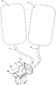
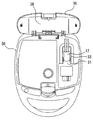
以下、添付図面の図1〜6を参照して、本発明に係る使い捨て電極及びそれの使用期限自動認識装置を実施するための最良の形態について説明する。各図において同一の構成要素には同一の符号を付して、重複する説明を省略する。除細動器に用いる使い捨て電極は、図1に示されるように、2枚の電極パッド11とコネクタ12との間が2本のケーブル13により接続された構成となっている。2枚の電極パッド11は、2本のケーブルの中間部分までと一緒に密封されて袋詰めされる。袋詰めされた電極パッド11は、蓋39を開けた状態の図2に示される除細動器本体30のコネクタ31にコネクタ12が接続された状態で、蓋39の裏側(内側)の電極収容部38に配置される。
DETAILED DESCRIPTION OF THE PREFERRED EMBODIMENTS A best mode for carrying out a disposable electrode according to the present invention and its automatic expiration date recognition device will be described below with reference to FIGS. In each figure, the same components are denoted by the same reference numerals, and redundant description is omitted. As shown in FIG. 1, the disposable electrode used for the defibrillator has a configuration in which two
コネクタ12は、直方体状のコネクタ筐体21の、使用状態における底面22に、底面22から垂直に突出していると共に、除細動器本体30に設けられたコネクタ31に接続する方向に、長い板状のフィン27が設けられている。このフィン27は、情報保持部23を備えている。
The
情報保持部23には、8個の円形の透孔を所定の穿設位置24に穿設することができるようになっており、例えば、透孔が穿設されている場合を「1」とし、透孔が穿設されていない場合を「0」として、8ビットの情報を保持させることができる。本実施の形態においては、情報保持部23に次の3種類の情報を保持させている。すなわち、ケーブル13側から連続して6個の透孔の穿設位置へ使い捨て電極の使用期限を示す情報を保持させ、次の1個の穿設位置へ使い捨て電極がトレーニング用電極であるか、または正規使用する電極であるかを示す電極種別情報を保持させ、次の1個の穿設位置へコネクタ12が除細動器本体30のコネクタ31に適正に接続されたか否かを示す接続情報を保持させている。
In the
なお、本実施の形態においては、情報保持部23に8個の円形の透孔を穿設することができるようにしたが、情報量の多少によって透孔の数を増減することができる。また、透孔は円形に限らず、例えば図6に示すように、スリットSでも良く、これも透孔に含まれるものである。さらに、電極種別情報に1ビットを割り当てたが、トレーニング用電極には使用期限情報は不要なため、トレーニング用電極の識別として、例えば全ての透孔を穿設しないなど、特別なビットパターンとすることもできる。このようにすると、電極種別情報のための透孔は不要となる。
In the present embodiment, eight circular through holes can be formed in the
使用期限情報及び電極種別情報それぞれに対応した透孔の穿設位置は、それぞれの情報に応じて透孔が穿設されているか、または穿設されていない状態となっている。接続情報に対応した透孔の穿設位置は、除細動器本体のコネクタ31に接続する方向の最も先端に位置する穿設位置24aとなっており、透孔は穿設されていない。これは、コネクタ12とコネクタ31との接続が不完全な場合、後述する光源と受光素子との間を、遮るものがないためである。
The through-hole drilling positions corresponding to the expiration date information and the electrode type information are in a state where the through-holes are drilled or not drilled according to the respective information. The through hole drilling position corresponding to the connection information is the
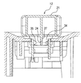
除細動器本体30は、図4に示されるように、光源である8個の発光ダイオード(LED)34及び受光素子である8個のフォトダイオード35を備えており、LED34及びフォトダイオード35はそれぞれ一対ずつ、コネクタ12が除細動器本体30のコネクタ31に適正に接続された状態において、情報保持部23の8個の透孔のそれぞれの穿設位置24を挟むように対向配置されている。なお、LED34などの光源は、射出光が穿設されている透孔を通って、その透孔に対応するフォトダイオード35などの受光素子に十分に受光される光量を有するものであれば、透孔の穿設位置24の数より少なくても良い。
As shown in FIG. 4, the
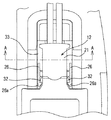
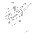
コネクタ12の一対の側壁には、図3に示されるように、コネクタ12と除細動器本体30のコネクタ31との接続状態を維持させる挟持アーム26が備えられ、挟持アーム26の先端には、内側に屈曲した爪部26aが形成されている。一方、除細動器本体30には係止突起32が形成されており、コネクタ12とコネクタ31とが適正に接続されたとき、爪部26aと係止突起32とが係合して両コネクタの接続状態が維持される。この接続状態において、8個のLED34及び8個のフォトダイオード35はそれぞれ対応する透孔の穿設位置24と正対し、透孔の穿設状況に従ってフォトダイオード35で検出される光量に基づいて使い捨て電極の情報を検出することができる。
As shown in FIG. 3, a pair of side walls of the
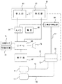
本実施の形態に係る使い捨て電極の使用期限自動認識装置を含む自動体外式除細動器の回路構成を図5に示す。2枚の電極パッド11にケーブル13を介して接続されたコネクタ12と接続されている除細動器本体30のコネクタ31からは、信号ライン51が心電信号を検出するための心電信号検出部68へ延びていると共に、電極パッド11への高電圧供給ライン52が、電極パッド11に印加する高電圧を発生させるための高圧部67へ延びている。
FIG. 5 shows a circuit configuration of an automatic external defibrillator including the disposable electrode expiration date automatic recognition device according to the present embodiment. An electrocardiogram signal detection for the
符号61は、コネクタ12の情報保持部23に保持されている使い捨て電極の情報を検出するための検出部であって、8個のLED34を含む発光部62と、8個のフォトダイオード35を含む受光部63とを有しており、前述のフィン27に形成される情報保持部23が発光部62と受光部63との間に配置されている。発光部62はCPU60からの指示信号によりLED34を発光させ、受光部63からは、情報保持部23に穿設された透孔及び穿設されていない透孔に対応する信号が得られ、A/D変換器64へ送出される。
A/D変換器64はアナログ信号をディジタル化してCPU60へ送出するものである。制御手段としてのCPU60には、上記A/D変換器64の他、除細動のための高電圧を電極パッド11を介して生体に印加するための始動スイッチ71、報知手段としての可視表示器72、音声報知を行うスピーカ73、及び高圧部67が接続されている。心電信号検出部68の出力はA/D変換器64に送出される。また、各部には、電源部66から電源が供給される。
The A /
以上のように構成された、本実施の形態に係る使い捨て電極の使用期限自動認識装置を含む自動体外式除細動器の作動を次に説明する。図示しない電源スイッチをオンすると、除細動のための作動が開始される。CPU60は、装置の状態や操作方法の案内を可視表示器72へ表示し、スピーカ73から操作案内等の音声を出力させる。また、A/D変換器64からの心電信号に基づいて、除細動が必要であるか否かを判別し、その判別結果に応じて、可視表示器72やスピーカ73から所要の情報を出力させると共に、除細動が必要と判別された場合は、除細動のための高電圧を発生させるべく、高圧部67を制御する。以上は、従来通りの作動である。
The operation of the automatic external defibrillator including the disposable electrode expiration date automatic recognition device according to the present embodiment configured as described above will be described below. When a power switch (not shown) is turned on, an operation for defibrillation is started. The
次に、情報保持部23に保持されている使い捨て電極に係る情報の自動認識について説明する。情報保持部23に保持されている情報は、図示しないタイマにより、所定時間毎、或いは1日1回所定の時刻に自動認識に係る回路が起動されて、自動的に検出され、報知される。CPU60は、受光部63により捕らえられた、情報保持部23の穿設位置24に穿設されている透孔及び穿設されていない透孔に対応する信号がA/D変換器64から到来するので、この信号(8ビット)に基づき、コネクタ12が除細動器本体30のコネクタ31に適正に接続されているかを検出し、使用期限を検出し、電極がトレーニング用電極であるかまたは正規使用する電極であるかという電極種別を検出して、可視表示器72やスピーカ73で報知する。
Next, automatic recognition of information related to the disposable electrode held in the
コネクタ12が除細動器本体30のコネクタ31に適正に接続されていないことが検出された場合には、使用期限や電極種別の検出は不可能或いは誤検出となる可能性があるため、使用期限や電極種別の検出は行わない。コネクタ12と除細動器本体30のコネクタ31との接続状態が適切でない場合には、「コネクタが外れています」などの警告が可視表示器72やスピーカ73を介してなされる。
If it is detected that the
コネクタ12が除細動器本体30のコネクタ31に適正に接続されていることが検出されると、CPU60は、使用期限や電極種別の検出を行い、これらの情報を可視表示器72やスピーカ73へ送り出力する。出力する使用期限情報としては、年と月による使用期限自体であっても良いし、使用期限までの期間を「使用期限まで○年○か月」のように表現したものでも良い。また、電極種別の出力に関しては、トレーニング用の電極が接続されている場合に、「トレーニング用の電極がセットされています」など、注意喚起の情報が可視表示器72やスピーカ73を介してなされる。
When it is detected that the
このように所定時間毎、或いは1日1回所定の時刻に、自動的に、コネクタ12とコネクタ31との接続状態、使い捨て電極の使用期限、及び電極種別を点検することができる。また、透孔の有無を光により検出する構成を採用しているので、接点などのような経時変化がなく、安定した精度の良い点検が可能である。
As described above, the connection state between the
以上の説明においては、タイマにより、所定時間毎、或いは1日1回所定の時刻に点検を行うものとしたが、別途点検スイッチを設け、任意のタイミングで点検を行えるようにしても良く、また、除細動器本体30の蓋39を開けたときなどの所要のタイミングを捕らえて点検を行うようにしても良い。更に、これらの点検方法を組み合わせても良い。
In the above description, the inspection is performed at a predetermined time by a timer or once a day at a predetermined time. However, a separate inspection switch may be provided so that the inspection can be performed at an arbitrary timing. The inspection may be performed by catching a required timing such as when the
次に、本発明を実施するための第2の形態について、図7を用いて説明する。前述した本発明を実施するための最良の形態に対して、透孔の有無を検出する検出手段が異なるのみであるので、同一構成部分には同一符号を付して、重複する説明を省略する。透孔の有無を検出する検出手段は、図7に示すように、フィン27を挟んで、バネ83により突出する接点82を備える可動部81と、突出した接点82と接触する固定接点92を備える検出部91とを透孔の穿設位置24を挟んで対向配置し、可動部81と検出部91との接触を電流を流して検出する構成とする。透孔が穿設されていれば、接点82は固定接点92と接触し、透孔が穿設されていなければ、接点82は固定接点92と接触しない。
Next, the 2nd form for implementing this invention is demonstrated using FIG. Since only the detection means for detecting the presence or absence of a through hole is different from the best mode for carrying out the present invention described above, the same components are denoted by the same reference numerals, and redundant description is omitted. . As shown in FIG. 7, the detection means for detecting the presence or absence of the through hole includes a
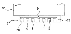
次に、本発明を実施するための第3の形態について、図8、図9を用いて説明する。前述した本発明を実施するための最良の形態に対して、使い捨て電極の情報を保持する情報保持部と情報保持部の情報を検出する検出手段とが異なるのみであるので、同一構成部分には同一符号を付して、重複する説明を省略する。図8は、使い捨て電極のコネクタ112の斜視図であり、図9は、図8におけるB−B断面図である。情報保持部123は、使い捨て電極のコネクタ112の底面122に備えられており、光反射部材としての反射シール129を貼付位置124に8個貼付することができるようになっている。情報保持部123及びその周辺は、例えば黒色の反射しにくい構造となっており、一方、反射シール129は、表面がなめらかで、白色、銀色等の反射しやすい色を用いた円形の薄いシールで、粘着剤や接着剤で反射シール貼付位置124に貼付可能となっている。例えば、反射シール129が貼付されている場合を「1」、反射シール129が貼付されていない場合を「0」として、8ビットの情報を保持させることができる。なお、反射シール129を貼付する代わりに、保持させる情報に応じて反射・非反射のパターンが予め印刷された一枚のシールを、貼付位置124に合わせて貼付しても良い。
Next, the 3rd form for implementing this invention is demonstrated using FIG. 8, FIG. In contrast to the best mode for carrying out the present invention described above, the information holding unit for holding the information on the disposable electrode and the detection means for detecting the information on the information holding unit are different. The same reference numerals are given, and duplicate descriptions are omitted. FIG. 8 is a perspective view of the
本実施の形態における情報保持部123に保持させる情報及びその位置は、前述の最良の形態と同様に、ケーブル13側から、使用期限情報、電極種別情報、及び接続情報である。なお、接続情報は、反射シール129を貼付している。これは、コネクタ112とコネクタ31との接続が不完全な場合、後述する、光源からの光を受光素子が受光することがないためである。
The information to be held in the
除細動器本体30には、図9に示されるように、8個の反射型フォトインタラプタ136が備えられている。反射型フォトインタラプタ136は、光源であるLED134と受光素子であるフォトトランジスタ135とが一体化されているものであり、LED134で発光した光の反射光をフォトトランジスタ135で受光し、物体を検知するものである。それぞれの反射型フォトインタラプタ136は、コネクタ112が除細動器本体30のコネクタ31に適正に接続された状態において、情報保持部123の8個の反射シール貼付位置124それぞれに対応するように配置されている。反射シール129が貼付位置124に貼付されていると、LED134で発光した光が反射シール129で反射され、フォトトランジスタ135で受光する。
As shown in FIG. 9, the defibrillator
本実施の形態における情報保持部123に保持されている使い捨て電極に係る情報の自動認識は、前述の最良の形態と同様に実行される。
Automatic recognition of information related to the disposable electrode held in the
11 電極パッド 12、112 コネクタ
21、121 コネクタ筐体 23、123 情報保持部
24 穿設位置 24a 穿設位置
27 フィン 30 除細動器本体
31 除細動器本体のコネクタ 34、134 LED
35 フォトダイオード 61 検出部
62 発光部 63 受光部
64 A/D変換器 66 電源部
67 高圧部 68 心電信号検出部
71 始動スイッチ 72 可視表示器
73 スピーカ 124 貼付位置
129 反射シール 135 フォトトランジスタ
136 反射型フォトインタラプタ
DESCRIPTION OF
35
Claims (5)
前記情報保持部は、前記コネクタの筐体に複数の透孔または光反射部材を配設可能とされ、それぞれの透孔または光反射部材の有無により、少なくとも使用期限に係る情報を保持するように構成されていることを特徴とする使い捨て電極。 A disposable electrode comprising an electrode pad and a connector for connecting the electrode pad to a defibrillator body, the connector comprising an information holding unit for holding information relating to the disposable electrode, wherein the connector is removed from the connector. In a disposable electrode connected to a fibrillator body so that the information can be reported from the defibrillator body,
The information holding unit can be provided with a plurality of through holes or light reflecting members in the housing of the connector, and holds at least information related to the expiration date depending on the presence or absence of each through hole or light reflecting member. A disposable electrode characterized in that it is configured.
前記除細動器本体は、
前記コネクタが前記除細動器本体に接続された状態において前記情報保持部の透孔または光反射部材の有無を検出する検出手段と、
前記情報を報知する報知手段と、
前記検出手段により得られる信号に基づき、前記使い捨て電極の情報を得ると共に、この情報を前記報知手段に報知させる制御手段と、
を具備することを特徴とする使い捨て電極の使用期限自動認識装置。 It is an expiration date automatic recognition apparatus of the disposable electrode according to any one of claims 1 to 3,
The defibrillator body is
Detecting means for detecting the presence or absence of a through-hole or a light reflecting member of the information holding unit in a state where the connector is connected to the defibrillator body;
An informing means for informing the information;
Based on the signal obtained by the detection means, the information of the disposable electrode is obtained, and the control means for notifying the information means of the information,
An expiration date automatic recognition device for disposable electrodes, comprising:
Priority Applications (3)
| Application Number | Priority Date | Filing Date | Title |
|---|---|---|---|
| JP2008234955A JP5196311B2 (en) | 2008-09-12 | 2008-09-12 | Disposable electrode and automatic expiration date recognition device thereof |
| US12/558,464 US9211399B2 (en) | 2008-09-12 | 2009-09-11 | Disposable electrode and automatic information recognition apparatus |
| EP09170060.9A EP2165732B1 (en) | 2008-09-12 | 2009-09-11 | Disposable electrode and automatic information recognition apparatus |
Applications Claiming Priority (1)
| Application Number | Priority Date | Filing Date | Title |
|---|---|---|---|
| JP2008234955A JP5196311B2 (en) | 2008-09-12 | 2008-09-12 | Disposable electrode and automatic expiration date recognition device thereof |
Publications (2)
| Publication Number | Publication Date |
|---|---|
| JP2010063771A true JP2010063771A (en) | 2010-03-25 |
| JP5196311B2 JP5196311B2 (en) | 2013-05-15 |
Family
ID=41172339
Family Applications (1)
| Application Number | Title | Priority Date | Filing Date |
|---|---|---|---|
| JP2008234955A Active JP5196311B2 (en) | 2008-09-12 | 2008-09-12 | Disposable electrode and automatic expiration date recognition device thereof |
Country Status (3)
| Country | Link |
|---|---|
| US (1) | US9211399B2 (en) |
| EP (1) | EP2165732B1 (en) |
| JP (1) | JP5196311B2 (en) |
Cited By (3)
| Publication number | Priority date | Publication date | Assignee | Title |
|---|---|---|---|---|
| JP2010099427A (en) * | 2008-10-21 | 2010-05-06 | Minato Ikagaku Kk | Electrical stimulator with electrode identification function |
| JP2014155793A (en) * | 2013-02-14 | 2014-08-28 | Heart Sign Technologies Ltd | Defibrillator electrode identification system |
| JP2015150182A (en) * | 2014-02-14 | 2015-08-24 | オージー技研株式会社 | Electrostimulator |
Families Citing this family (7)
| Publication number | Priority date | Publication date | Assignee | Title |
|---|---|---|---|---|
| US9415217B2 (en) * | 2014-07-10 | 2016-08-16 | Eric Ye Chen | Wireless electrical stimulation system |
| US11351361B2 (en) | 2014-07-10 | 2022-06-07 | Hi-Dow Iphc, Inc. | Wireless electrical stimulation system |
| US10668282B2 (en) | 2014-07-10 | 2020-06-02 | Eric Ye Chen | Wireless electrical stimulation system |
| JP6289303B2 (en) * | 2014-08-08 | 2018-03-07 | 日本光電工業株式会社 | Defibrillator |
| USD816227S1 (en) | 2016-03-29 | 2018-04-24 | Sanofi | Electrical stimulation device |
| CN111375133A (en) * | 2018-12-29 | 2020-07-07 | 深圳迈瑞生物医疗电子股份有限公司 | External defibrillator |
| USD991467S1 (en) * | 2020-12-04 | 2023-07-04 | Rehabtronics Inc. | Electrode assembly for electrical stimulation |
Citations (5)
| Publication number | Priority date | Publication date | Assignee | Title |
|---|---|---|---|---|
| JPS58111163A (en) * | 1981-12-22 | 1983-07-02 | Matsushita Electric Ind Co Ltd | Information detection tape cassette |
| JPS58215747A (en) * | 1982-06-08 | 1983-12-15 | Matsushita Electric Ind Co Ltd | Magnetic recording and reproducing device |
| JPH03204713A (en) * | 1990-01-08 | 1991-09-06 | Hitachi Ltd | Power control circuit for input/output interface |
| WO2006102420A2 (en) * | 2005-03-21 | 2006-09-28 | Defibtech, Llc | Pcb blade connector system and method |
| JP2008523878A (en) * | 2004-12-20 | 2008-07-10 | コーニンクレッカ フィリップス エレクトロニクス エヌ ヴィ | Automatic external defibrillator for adult and pediatric patients |
Family Cites Families (7)
| Publication number | Priority date | Publication date | Assignee | Title |
|---|---|---|---|---|
| FR2720947B1 (en) | 1994-06-09 | 1996-08-09 | Odam Off Distri App Medicaux | Defibrillator apparatus having a plurality of connector / electrode assemblies of different types. |
| JP4103101B2 (en) | 2000-02-10 | 2008-06-18 | 日本光電工業株式会社 | Defibrillation electrode and defibrillation system |
| US6694193B2 (en) * | 2001-09-14 | 2004-02-17 | Koninklijke Philips Electronics N.V. | Medical electrode and release liner configurations facilitating packaged electrode characterization |
| JP2008525084A (en) * | 2004-12-27 | 2008-07-17 | コーニンクレッカ フィリップス エレクトロニクス エヌ ヴィ | Method and apparatus for communicating with an OTC automatic external defibrillator |
| US7590456B2 (en) * | 2005-02-10 | 2009-09-15 | Zoll Medical Corporation | Triangular or crescent shaped defibrillation electrode |
| JP4631027B2 (en) | 2005-03-29 | 2011-02-16 | 独立行政法人産業技術総合研究所 | IC tag mounted biosensor and its package |
| JP2006275923A (en) | 2005-03-30 | 2006-10-12 | Terumo Corp | Electrode type biosensor |
-
2008
- 2008-09-12 JP JP2008234955A patent/JP5196311B2/en active Active
-
2009
- 2009-09-11 US US12/558,464 patent/US9211399B2/en active Active
- 2009-09-11 EP EP09170060.9A patent/EP2165732B1/en active Active
Patent Citations (5)
| Publication number | Priority date | Publication date | Assignee | Title |
|---|---|---|---|---|
| JPS58111163A (en) * | 1981-12-22 | 1983-07-02 | Matsushita Electric Ind Co Ltd | Information detection tape cassette |
| JPS58215747A (en) * | 1982-06-08 | 1983-12-15 | Matsushita Electric Ind Co Ltd | Magnetic recording and reproducing device |
| JPH03204713A (en) * | 1990-01-08 | 1991-09-06 | Hitachi Ltd | Power control circuit for input/output interface |
| JP2008523878A (en) * | 2004-12-20 | 2008-07-10 | コーニンクレッカ フィリップス エレクトロニクス エヌ ヴィ | Automatic external defibrillator for adult and pediatric patients |
| WO2006102420A2 (en) * | 2005-03-21 | 2006-09-28 | Defibtech, Llc | Pcb blade connector system and method |
Cited By (3)
| Publication number | Priority date | Publication date | Assignee | Title |
|---|---|---|---|---|
| JP2010099427A (en) * | 2008-10-21 | 2010-05-06 | Minato Ikagaku Kk | Electrical stimulator with electrode identification function |
| JP2014155793A (en) * | 2013-02-14 | 2014-08-28 | Heart Sign Technologies Ltd | Defibrillator electrode identification system |
| JP2015150182A (en) * | 2014-02-14 | 2015-08-24 | オージー技研株式会社 | Electrostimulator |
Also Published As
| Publication number | Publication date |
|---|---|
| US20100070011A1 (en) | 2010-03-18 |
| EP2165732A1 (en) | 2010-03-24 |
| JP5196311B2 (en) | 2013-05-15 |
| US9211399B2 (en) | 2015-12-15 |
| EP2165732B1 (en) | 2013-04-10 |
Similar Documents
| Publication | Publication Date | Title |
|---|---|---|
| JP5196311B2 (en) | Disposable electrode and automatic expiration date recognition device thereof | |
| US8771233B2 (en) | Medication administering device | |
| ES2358728T3 (en) | TIMED ALARM DEVICE FOR USE TOGETHER WITH A GROUND-TO-GROUND PROTECTION DEVICE. | |
| JP3186753U (en) | Power saving lighting device with voice control module | |
| JP6956792B2 (en) | Electrical plug-in connector with plug-in cycle counter and how to operate it | |
| JP2015535184A (en) | Flexible lightweight physiological monitor | |
| JP2007129568A5 (en) | ||
| US7652590B2 (en) | Thin emergency exit indication and warning device | |
| RU2005129846A (en) | SYSTEM AND METHOD OF DISPLAY DEVICE WITH EFFECTS OF THE END OF LIFE | |
| JP2017508558A5 (en) | ||
| EP2159765A1 (en) | Position and operation signalling apparatus for fire extinguishers and fire extinguishing system comprising such an apparatus | |
| JP2006053110A (en) | Water wetting detecting seal, water wetting detector, and electronic apparatus using same | |
| GB2460721A (en) | Electrical apparatus having operation status indicator which cn transmit parameter values | |
| JP3533167B2 (en) | Mobile terminal equipment | |
| JPWO2018151069A1 (en) | Charging system, electronic device and charging device | |
| US7980128B2 (en) | Level monitoring system | |
| JP5444636B2 (en) | Power supply | |
| JP6418485B2 (en) | Switch device | |
| JP4910813B2 (en) | Electric wire connector, lighting device | |
| JP4521216B2 (en) | Display system | |
| JP5258689B2 (en) | Product theft detector and product theft monitoring device | |
| JP2008235112A (en) | Lighting monitoring device and lighting system | |
| CN214475380U (en) | Alarm device | |
| JP2010054372A (en) | Schedule annunciation device | |
| JP2008272023A (en) | Biomedical electrode package unit and method for determining quality of biomedical electrode |
Legal Events
| Date | Code | Title | Description |
|---|---|---|---|
| A621 | Written request for application examination |
Free format text: JAPANESE INTERMEDIATE CODE: A621 Effective date: 20101215 |
|
| A131 | Notification of reasons for refusal |
Free format text: JAPANESE INTERMEDIATE CODE: A131 Effective date: 20120710 |
|
| A977 | Report on retrieval |
Free format text: JAPANESE INTERMEDIATE CODE: A971007 Effective date: 20120712 |
|
| A521 | Request for written amendment filed |
Free format text: JAPANESE INTERMEDIATE CODE: A523 Effective date: 20120907 |
|
| A131 | Notification of reasons for refusal |
Free format text: JAPANESE INTERMEDIATE CODE: A131 Effective date: 20121002 |
|
| A521 | Request for written amendment filed |
Free format text: JAPANESE INTERMEDIATE CODE: A523 Effective date: 20121129 |
|
| TRDD | Decision of grant or rejection written | ||
| A01 | Written decision to grant a patent or to grant a registration (utility model) |
Free format text: JAPANESE INTERMEDIATE CODE: A01 Effective date: 20130108 |
|
| A61 | First payment of annual fees (during grant procedure) |
Free format text: JAPANESE INTERMEDIATE CODE: A61 Effective date: 20130124 |
|
| FPAY | Renewal fee payment (event date is renewal date of database) |
Free format text: PAYMENT UNTIL: 20160215 Year of fee payment: 3 |
|
| R150 | Certificate of patent or registration of utility model |
Ref document number: 5196311 Country of ref document: JP Free format text: JAPANESE INTERMEDIATE CODE: R150 Free format text: JAPANESE INTERMEDIATE CODE: R150 |
|
| R250 | Receipt of annual fees |
Free format text: JAPANESE INTERMEDIATE CODE: R250 |
|
| R250 | Receipt of annual fees |
Free format text: JAPANESE INTERMEDIATE CODE: R250 |
|
| R250 | Receipt of annual fees |
Free format text: JAPANESE INTERMEDIATE CODE: R250 |
|
| R250 | Receipt of annual fees |
Free format text: JAPANESE INTERMEDIATE CODE: R250 |