JP2010063317A - Exterior structure of wire harness - Google Patents
Exterior structure of wire harness Download PDFInfo
- Publication number
- JP2010063317A JP2010063317A JP2008228846A JP2008228846A JP2010063317A JP 2010063317 A JP2010063317 A JP 2010063317A JP 2008228846 A JP2008228846 A JP 2008228846A JP 2008228846 A JP2008228846 A JP 2008228846A JP 2010063317 A JP2010063317 A JP 2010063317A
- Authority
- JP
- Japan
- Prior art keywords
- tube
- wire harness
- wire
- exposed
- knitted
- Prior art date
- Legal status (The legal status is an assumption and is not a legal conclusion. Google has not performed a legal analysis and makes no representation as to the accuracy of the status listed.)
- Granted
Links
Images


Abstract
Description
本発明は、ワイヤハーネスの外装構造に関し、詳しくは、ワイヤハーネス内の電線間に浸入した水を外部へと排水できる外装構造に関する。 The present invention relates to an exterior structure of a wire harness, and more particularly to an exterior structure that can drain water that has entered between wires in the wire harness to the outside.
従来より、車両に配索されるワイヤハーネスは、塩化ビニルテープ等でハーフラップ巻きしたり、樹脂製のビニルチューブや硬質ビニルチューブからなる丸チューブやコルゲートチューブを取り付けて外装して、電線の保持、拘束、あるいは、接触や擦れなどの外部干渉からの電線保護を図っている。 Conventionally, wire harnesses that are routed on vehicles are half-wrapped with vinyl chloride tape, etc., or attached with a round tube or corrugated tube made of resin vinyl tube or hard vinyl tube to hold the wire. , Restraint, or wire protection from external interference such as contact and rubbing.
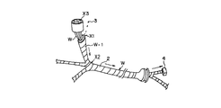
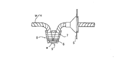
一方、図12に示すように、エンジンルーム等の被水領域において、ワイヤハーネスWの上下方向に配線する部分W−1におけるテープ2の巻端箇所X1、ワイヤハーネスの分岐点X2、コネクタの上向き開口部X3などから水滴3が電線1の線間に浸水することがある。この場合、線間に浸水した水滴3はハーフラップ巻きしたテープ2により外部に排出できずに溜まり、毛細管現象によりコネクタ4にまで達する場合がある。このようにコネクタ4に浸水が発生するとショートを生じる危険があり、かつ、浸水領域にスプライス部がある場合は、スプライス部に錆を発生させ、品質低下を招くおそれもある。
On the other hand, as shown in FIG. 12, in a wet area such as an engine room, the winding end X1 of the
前記問題に対して、特開昭60−96122号(特許文献1)では図13に示す排水構造を提案している。これは、ワイヤハーネスW/Hをエンジンルーム側の車体パネル5の近傍部分にU字状に屈曲させてプロテクタ6とテープ7巻きで固定し、該屈曲部8を下向きに突出させて配置する一方、該屈曲部8の先端にテープ巻きをせずに電線wを露出させた排水部9を設けたもので、これにより、ワイヤハーネスW/H内の電線wとテープ7との隙間から浸入した水を前記排水部9より排出するようにしている。 To solve the above problem, Japanese Patent Laid-Open No. 60-96122 (Patent Document 1) proposes a drainage structure shown in FIG. This is because the wire harness W / H is bent in a U-shape in the vicinity of the vehicle body panel 5 on the engine room side and fixed with a protector 6 and tape 7 and the bent portion 8 is protruded downward. The drainage part 9 in which the electric wire w is exposed without winding the tape around the tip of the bent part 8 is provided, so that it enters from the gap between the electric wire w and the tape 7 in the wire harness W / H. Water is discharged from the drainage part 9.
しかしながら、前記排水部9は、外装材であるテープ7を巻き付けない電線露出部であるため、車両走行中にはね上げた小石との衝突や、車体パネルのエッジとの接触、あるいは、他部品による干渉や挟み込み等の外力から電線を保護することができず、該露出部の電線が損傷する虞れがある。 However, since the drainage part 9 is an exposed part of the electric wire that does not wind the tape 7 as the exterior material, it collides with the pebbles that are raised while the vehicle is running, contacts with the edge of the vehicle body panel, or interference by other parts. Otherwise, the electric wire cannot be protected from external force such as pinching, and the exposed portion of the electric wire may be damaged.
本発明は前記問題に鑑みてなされたもので、ワイヤハーネスの電線群と外装材との隙間から入り込み、毛細管現象によって内部へと浸入していく水を外部へ排出できると共に、電線損傷も防ぐことができるワイヤハーネスの外装構造の提供を課題としている。 The present invention has been made in view of the above problems, and it is possible to discharge water that enters through a gap between the wire group of the wire harness and the exterior material and enters the inside by capillary action to the outside, and also prevents damage to the wire. It is an object to provide an external structure of a wire harness that can be used.
前記課題を解決するために、本発明は、車両の被水領域に配索されるワイヤハーネスの下端位置を挟む両側部はワイヤハーネスの電線群にテープをハーフラップ巻きしている、あるいは樹脂製の丸チューブ又はコルゲートチューブからなるチューブを通している一方、前記下端位置ではテープ巻き又はチューブを通さずに電線群を露出させており、
前記電線群を露出させた領域を、網目状に編成された編みチューブからなる外装材で被覆し、該ワイヤハーネス内に浸水した水を編みチューブの空隙から排水できる構成としていることを特徴とするワイヤハーネスの外装構造を提供している。
In order to solve the above-mentioned problem, the present invention is configured such that both sides sandwiching the lower end position of the wire harness routed in the wet area of the vehicle are half-wrapped with a tape around the wire group of the wire harness, or made of resin. While passing through a tube made of a round tube or a corrugated tube, the lower end position exposes the wire group without passing the tape or tube,
The region where the electric wire group is exposed is covered with an exterior material made of a knitted tube knitted in a mesh shape, and the water immersed in the wire harness can be drained from the gap of the knitted tube. It provides an exterior structure for a wire harness.
このように排水目的で電線群を露出させた部分を前記編みチューブで外装することにより、車両走行中にはね上げた小石や車体パネル等の他部品との干渉から電線露出部を保護して電線の損傷を防止できると共に、前記テープやチューブと電線群との隙間から浸入した水を溜めることなく編みチューブの網目の空隙から外部へと排出することができるため、優れた排水性と電線保護性能とを具備することができる。
また、編みチューブは、縮み方向に力を加えて圧縮することによりチューブ径を大きくすることができるため、ハーネスへの後通しが可能となり、作業性を高めることができる。
Thus, by covering the exposed portion of the wire group for the purpose of drainage with the knitted tube, the exposed portion of the wire is protected from interference with other parts such as pebbles and body panels that are raised while the vehicle is running. As well as preventing damage, water that has entered from the gap between the tape or tube and the wire group can be discharged outside through the mesh space of the knitted tube, so it has excellent drainage and wire protection performance. Can be provided.
Further, since the tube diameter can be increased by compressing the knitted tube by applying a force in the shrinking direction, the knitted tube can be passed through the harness and workability can be improved.
前記編みチューブの外周に、樹脂帯を螺旋状に巻いてチューブ状としたスパイラルチューブからなる外装材を重ねて取り付けてもよい。
前記スパイラルチューブは螺旋状の空隙を有し、この空隙から水をチューブ外へ排出することができるため、このスパイラルチューブを前記編みチューブの外周に重ねて取り付けることにより、排水性を低下させることなく電線保護性能を高めることができる。
On the outer periphery of the knitted tube, an exterior material made of a spiral tube formed by spirally winding a resin band may be attached.
Since the spiral tube has a spiral gap and water can be discharged from the gap to the outside of the tube, the spiral tube is attached to the outer periphery of the knitted tube without being deteriorated in drainage. Electric wire protection performance can be improved.
また、本発明は、車両の被水領域に配索されるワイヤハーネスの下端位置を挟む両側部はワイヤハーネスの電線群にテープをハーフラップ巻きしている、あるいは樹脂製の丸チューブ又はコルゲートチューブからなるチューブを通している一方、前記下端位置ではテープ巻き又はチューブを通さずに電線群を露出させており、
前記電線群を露出させた領域を、樹脂帯を螺旋状に巻いてチューブ状としたスパイラルチューブからなる外装材で被覆し、該ワイヤハーネス内に浸水した水をスパイラルチューブの空隙から排水できる構成としていることを特徴とするワイヤハーネスの外装構造も提供している。
In the present invention, both sides sandwiching the lower end position of the wire harness routed in the wet area of the vehicle are half-wrapped with a tape around the wire group of the wire harness, or a resin round tube or corrugated tube While passing through the tube consisting of, the wire group is exposed without passing the tape or tube at the lower end position,
The region where the wire group is exposed is covered with an exterior material made of a spiral tube in which a resin band is spirally wound, and the water immersed in the wire harness can be drained from the gap of the spiral tube. An exterior structure of a wire harness is also provided.
このように電線露出部をスパイラルチューブのみで外装する場合も、電線露出部を外力干渉から保護して電線損傷を防止できると共に、前記テープやチューブと電線群との隙間から浸入した水を溜めることなくスパイラルチューブの螺旋状の空隙から外部へと排出することができるため、優れた排水性と電線保護性能とを具備することができる。 Even when the exposed wire portion is covered only with a spiral tube in this way, the exposed wire portion can be protected from external force interference to prevent the wire from being damaged, and water that has entered from the gap between the tape or tube and the wire group can be collected. Since it can discharge | emit to the exterior from the helical space | gap of a spiral tube, it can comprise the outstanding drainage property and electric wire protection performance.
前記編みチューブまたはスパイラルチューブ、あるいは重ねた編みチューブとスパイラルチューブの外周面に締結バンド、バンド式クリップのバンド、または粘着テープを巻き付けて締結し、ワイヤハーネスとこれら外装材とを固定していることが好ましい。 The wire harness and the exterior material are fixed by winding a fastening band, a band-type clip band, or an adhesive tape around the outer circumference of the knitted tube or spiral tube or the stacked knitted tube and spiral tube. Is preferred.
前記締結バンドまたはバンド式クリップは、前記外装材の長さ方向両端部、長さ方向中間部、あるいは両端部と中間部の両方に締結してもよい。
バンド式クリップを外装材の長さ方向中間部に締結する場合は、該クリップを車体の所要位置に係止して電線露出部の最下端位置を保持することが好ましい。これにより、排水ポイントとなる最下端位置が電線露出部以外の箇所への位置ずれを防ぎ、排水機能低下を防止することができる。
The fastening band or the band-type clip may be fastened to both end portions in the length direction of the exterior material, an intermediate portion in the length direction, or both the end portions and the intermediate portion.
When the band-type clip is fastened to the intermediate portion in the longitudinal direction of the exterior material, it is preferable to hold the clip at a required position of the vehicle body to hold the lowermost position of the exposed wire portion. Thereby, the lowest end position used as a drainage point can prevent position shift to places other than an electric wire exposure part, and can prevent a drainage function fall.
上述したように、本発明によれば、ワイヤハーネスの下端位置を含む電線露出部を前記編みチューブまたは/および前記スパイラルチューブで外装することにより、電線露出部を外力干渉から保護して損傷を防止できると共に、電線間に浸入した水を前記外装材の網目や螺旋状の空隙を通じて外部へ排出することもでき、優れた排水性と電線保護性能とを具備することができる。 As described above, according to the present invention, by covering the exposed wire portion including the lower end position of the wire harness with the knitted tube and / or the spiral tube, the exposed wire portion is protected from external force interference to prevent damage. In addition, the water that has entered between the electric wires can be discharged to the outside through the mesh of the outer packaging material or the spiral gap, so that excellent drainage and electric wire protection performance can be provided.
以下、本発明の実施形態を図面を参照して説明する。
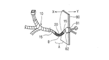
いずれの実施形態も、図1に示すように、自動車のエンジンルームに配索されるワイヤハーネス10の外装構造に本発明を適用している。ワイヤハーネス10は、自動車のエンジンルームXと車室Yとを仕切る車体パネル80の貫通穴81に取り付けられるグロメット82に挿通し、該グロメット82の取付位置近傍のエンジンルームX側に排水用の電線露出部Aを形成している。
前記電線露出部A以外の領域、即ち、電線露出部Aを挟む両側部はテープ15でハーフラップ巻きしている。テープ15は粘着テープからなる。
Hereinafter, embodiments of the present invention will be described with reference to the drawings.
In any of the embodiments, as shown in FIG. 1, the present invention is applied to the exterior structure of the
A region other than the exposed wire portion A, that is, both side portions sandwiching the exposed wire portion A are half-wrapped with a
また、いずれの実施形態も、ワイヤハーネス10は、前記電線露出部Aに最も低い位置B(以下「最下端位置B」という)が配置されるように下方に屈曲している。
In any of the embodiments, the
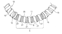
図1乃至図5に、本発明の第1実施形態を示す。
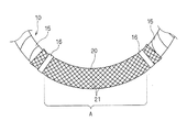
第1実施形態では、ワイヤハーネス10の前記電線露出部Aを網目状に編成された編みチューブ20で外装している。
1 to 5 show a first embodiment of the present invention.
In 1st Embodiment, the said electric wire exposure part A of the
前記編みチューブ20は、図2および図3に示すように、前記電線露出部Aを全長にわたって覆うと共にその両側部がテープ15のハーフラップ巻き部分の端部まで覆う長さとし、該両側部の外周面に締結バンド16を巻き付けて、ワイヤハーネス10に編みチューブ20を締結固定している。
As shown in FIGS. 2 and 3, the knitted
このように、電線露出部Aの全体を前記編みチューブ20で覆い、外部に露出させないことにより、車両走行中にはね上げた小石や車体パネル等との干渉から電線露出部Aを保護でき、電線損傷を防止することができる。また、電線群11とテープ15との隙間から浸入して電線間を伝い最下端位置Bに溜まってくる水は、図3に示すように、この最下端位置Bを含む電線露出部Aを覆う編みチューブ20の網目の空隙21から外部へと排出することができるため、ワイヤハーネス10内に水が溜まることを防止できる。
In this way, by covering the entire wire exposed portion A with the knitted
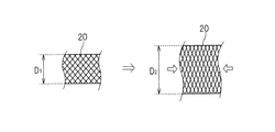
なお、前記編みチューブ20は、図4および図5に示すように、縮み方向に両側から力を加えることによりチューブ径をD1からD2に容易に大きくすることができるため、端末にコネクタ70を接続したり分岐部を形成したワイヤハーネス10に後通しすることができる。
As shown in FIGS. 4 and 5, the knitted
前記第一実施形態では、ワイヤハーネス10の電線露出部A以外の領域は、テープ15でハーフラップ巻きしているが、図6に示すように、テープでハーフラップ巻きする代わりにスリットなしのコルゲートチューブCTで外装してもよい。この場合、電線露出部Aに取り付ける前記編みチューブ20の両端は、コルゲートチューブCTの先端から所要寸法内部に位置し、コルゲートチューブCTの内部で編みチューブ20の両端を電線群11に締結バンドで固定している。
また、コルゲートチューブに代えて、ビニルチューブ、硬質ビニルチューブからなる樹脂製の丸チューブを用いてもよい。
In the first embodiment, the region other than the wire exposed portion A of the
Further, instead of the corrugated tube, a resin round tube made of a vinyl tube or a hard vinyl tube may be used.
図7に、本発明の第二実施形態を示す。
第二実施形態では、ワイヤハーネス10の最下端位置Bに、前記編みチューブ20の上からバンド式クリップ17を巻き付けて締結し、このバンド式クリップ17の車体係止部17aを車体パネル30の係止孔31に挿入係止して、前記最下端位置Bを保持している。その他の構成は前記第一実施形態と同一であるため、同一符合を付して説明を省略する。
FIG. 7 shows a second embodiment of the present invention.
In the second embodiment, the band-
このように、バンド式クリップ17でワイヤハーネス10の最下端位置Bを保持することにより、ワイヤハーネス10の屈曲形状を一定化でき、排水ポイントとなる最下端位置Bが電線露出部A以外の部分に移動することを防止できるため、常に安定した排水性を機能させることができる。
In this way, by holding the lowermost position B of the
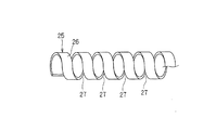
図8および図9に、本発明の第三実施形態を示す。
第3実施形態では、ワイヤハーネス10の前記電線露出部Aを、樹脂から成形したスパイラルチューブ25で外装している。該スパイラルチューブ25は、図9に示すように、樹脂帯26を螺旋状に巻いてチューブ状に予め成形している。
8 and 9 show a third embodiment of the present invention.
In 3rd Embodiment, the said electric wire exposure part A of the
前記スパイラルチューブ25の両端の外周面に締結バンド16を巻き付け締結して、スパイラルチューブ25をワイヤハーネス10に固定している。その他の構成は前記第一実施形態と同一であるため、同一符合を付して説明を省略する。
Fastening
本実施形態においては、スパイラルチューブ25で電線露出部Aを覆うことができるため、小石や車体パネル等との干渉による電線群損傷を防止できると共に、テープ15と電線群11との隙間から浸入して最下端位置Bに溜まってくる水を、前記スパイラルチューブ25の樹脂帯26間の螺旋状の空隙27から外部へと排出することができる。
In the present embodiment, the exposed wire portion A can be covered with the
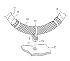
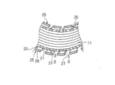
図10および図11に、本発明の第四実施形態を示す。
第四実施形態では、ワイヤハーネス10の電線露出部Aに編みチューブ20を取り付け、さらにこの編みチューブ20の外周に重ねて前記スパイラルチューブ25を取り付けて外装している。
10 and 11 show a fourth embodiment of the present invention.
In the fourth embodiment, the knitted
このように、電線露出部Aを編みチューブ20とスパイラルチューブ25とで二重に外装することにより、電線露出部Aが受ける外力干渉をより緩和することができるため、電線保護性能を高めることができる。また、編みチューブ20には網目の空隙21があり、スパイラルチューブ25には樹脂帯26間の螺旋状の空隙27があるため、図11に示すように、これらの空隙21、27を通じてワイヤハーネス10内の水を外部へと排出することもできる。よって、優れた排水性を備えたまま電線保護性能を高めることができる。
Thus, since the external force interference which the electric wire exposure part A receives can be relieve | moderated more by covering the electric wire exposure part A by the knitted
10 ワイヤハーネス
15 テープ
16 締結バンド
17 バンド式クリップ
20 編みチューブ
21 空隙
25 スパイラルチューブ
27 空隙
A 電線露出部
B 最下端位置
DESCRIPTION OF
Claims (4)
前記電線群を露出させた領域を、網目状に編成された編みチューブからなる外装材で被覆し、該ワイヤハーネス内に浸水した水を編みチューブの空隙から排水できる構成としていることを特徴とするワイヤハーネスの外装構造。 On both sides of the lower end position of the wire harness that is routed in the wet area of the vehicle, the tape is half-wrapped around the wires of the wire harness, or through a tube made of a resin round tube or corrugated tube In the lower end position, the wire group is exposed without passing the tape winding or the tube,
The region where the electric wire group is exposed is covered with an exterior material made of a knitted tube knitted in a mesh shape, and the water immersed in the wire harness can be drained from the gap of the knitted tube. Wire harness exterior structure.
前記電線群を露出させた領域を、樹脂帯を螺旋状に巻いてチューブ状としたスパイラルチューブからなる外装材で被覆し、該ワイヤハーネス内に浸水した水をスパイラルチューブの空隙から排水できる構成としていることを特徴とするワイヤハーネスの外装構造。 On both sides of the lower end position of the wire harness that is routed in the wet area of the vehicle, the tape is half-wrapped around the wires of the wire harness, or through a tube made of a resin round tube or corrugated tube In the lower end position, the wire group is exposed without passing the tape winding or the tube,
The region where the wire group is exposed is covered with an exterior material made of a spiral tube in which a resin band is spirally wound, and the water immersed in the wire harness can be drained from the space of the spiral tube. An exterior structure of a wire harness, characterized by comprising:
Priority Applications (1)
| Application Number | Priority Date | Filing Date | Title |
|---|---|---|---|
| JP2008228846A JP5083128B2 (en) | 2008-09-05 | 2008-09-05 | Wire harness exterior structure |
Applications Claiming Priority (1)
| Application Number | Priority Date | Filing Date | Title |
|---|---|---|---|
| JP2008228846A JP5083128B2 (en) | 2008-09-05 | 2008-09-05 | Wire harness exterior structure |
Publications (2)
| Publication Number | Publication Date |
|---|---|
| JP2010063317A true JP2010063317A (en) | 2010-03-18 |
| JP5083128B2 JP5083128B2 (en) | 2012-11-28 |
Family
ID=42189501
Family Applications (1)
| Application Number | Title | Priority Date | Filing Date |
|---|---|---|---|
| JP2008228846A Expired - Fee Related JP5083128B2 (en) | 2008-09-05 | 2008-09-05 | Wire harness exterior structure |
Country Status (1)
| Country | Link |
|---|---|
| JP (1) | JP5083128B2 (en) |
Cited By (8)
| Publication number | Priority date | Publication date | Assignee | Title |
|---|---|---|---|---|
| US20110083899A1 (en) * | 2008-06-03 | 2011-04-14 | Sumitomo Wiring Systems, Ltd. | Water drain structure for wire harness |
| JP2012056441A (en) * | 2010-09-09 | 2012-03-22 | Honda Motor Co Ltd | Harness wiring structure of saddle-riding type vehicle |
| JP2012115040A (en) * | 2010-11-24 | 2012-06-14 | Sumitomo Wiring Syst Ltd | Drainage structure of wire harness |
| WO2013108546A1 (en) * | 2012-01-20 | 2013-07-25 | Ntn株式会社 | Structure for protecting power cable |
| CN103311851A (en) * | 2013-06-27 | 2013-09-18 | 长城汽车股份有限公司 | Protective casing for automobile wire harness |
| CN104276110A (en) * | 2014-09-26 | 2015-01-14 | 北京新能源汽车股份有限公司 | Connector assembly with drainage function |
| JP2018101511A (en) * | 2016-12-19 | 2018-06-28 | 株式会社オートネットワーク技術研究所 | Wire harness |
| JP2018207754A (en) * | 2017-06-09 | 2018-12-27 | 株式会社豊田自動織機 | Electrical machine of vehicle |
Citations (2)
| Publication number | Priority date | Publication date | Assignee | Title |
|---|---|---|---|---|
| JP2001246993A (en) * | 2000-03-02 | 2001-09-11 | Sumitomo Wiring Syst Ltd | Wire harness arrangement structure between vehicle body and door |
| JP2007116782A (en) * | 2005-10-18 | 2007-05-10 | Yazaki Corp | Cabling device |
-
2008
- 2008-09-05 JP JP2008228846A patent/JP5083128B2/en not_active Expired - Fee Related
Patent Citations (2)
| Publication number | Priority date | Publication date | Assignee | Title |
|---|---|---|---|---|
| JP2001246993A (en) * | 2000-03-02 | 2001-09-11 | Sumitomo Wiring Syst Ltd | Wire harness arrangement structure between vehicle body and door |
| JP2007116782A (en) * | 2005-10-18 | 2007-05-10 | Yazaki Corp | Cabling device |
Cited By (11)
| Publication number | Priority date | Publication date | Assignee | Title |
|---|---|---|---|---|
| US20110083899A1 (en) * | 2008-06-03 | 2011-04-14 | Sumitomo Wiring Systems, Ltd. | Water drain structure for wire harness |
| US8530743B2 (en) * | 2008-06-03 | 2013-09-10 | Sumitomo Wiring Systems, Ltd. | Water drain structure for wire harness |
| JP2012056441A (en) * | 2010-09-09 | 2012-03-22 | Honda Motor Co Ltd | Harness wiring structure of saddle-riding type vehicle |
| JP2012115040A (en) * | 2010-11-24 | 2012-06-14 | Sumitomo Wiring Syst Ltd | Drainage structure of wire harness |
| WO2013108546A1 (en) * | 2012-01-20 | 2013-07-25 | Ntn株式会社 | Structure for protecting power cable |
| CN104067467A (en) * | 2012-01-20 | 2014-09-24 | Ntn株式会社 | Structure for protecting power cable |
| CN103311851A (en) * | 2013-06-27 | 2013-09-18 | 长城汽车股份有限公司 | Protective casing for automobile wire harness |
| CN103311851B (en) * | 2013-06-27 | 2016-01-20 | 长城汽车股份有限公司 | A kind of automotive wire bundle containment vessel |
| CN104276110A (en) * | 2014-09-26 | 2015-01-14 | 北京新能源汽车股份有限公司 | Connector assembly with drainage function |
| JP2018101511A (en) * | 2016-12-19 | 2018-06-28 | 株式会社オートネットワーク技術研究所 | Wire harness |
| JP2018207754A (en) * | 2017-06-09 | 2018-12-27 | 株式会社豊田自動織機 | Electrical machine of vehicle |
Also Published As
| Publication number | Publication date |
|---|---|
| JP5083128B2 (en) | 2012-11-28 |
Similar Documents
| Publication | Publication Date | Title |
|---|---|---|
| JP5083128B2 (en) | Wire harness exterior structure | |
| JP5151701B2 (en) | Drainage structure of wire harness | |
| US10790655B2 (en) | Grommet | |
| JP6248899B2 (en) | Wire harness seal structure | |
| JP2010047031A (en) | Method for manufacturing wire harness | |
| JP2008195182A (en) | Wire harness laying structure for door | |
| JP6422257B2 (en) | Grommet and wire harness using this grommet | |
| JP5957286B2 (en) | Wire harness water stop structure | |
| JP3622636B2 (en) | Bending structure of shielded wire and shielding method thereof | |
| JP2007288972A (en) | Protective structure of wire harness branching portion | |
| JP5166841B2 (en) | Protective member | |
| US20080092974A1 (en) | Conduit with securing flap | |
| JP7363624B2 (en) | wire harness | |
| JP3558541B2 (en) | Gummet with bellows and wire harness with grommet with bellows | |
| JP6759155B2 (en) | Vehicle electrical equipment | |
| JP2894144B2 (en) | Wire harness waterproof structure | |
| JP2007049784A (en) | Wiring structure of harness for automobile | |
| JP5505277B2 (en) | Wire harness drain structure | |
| JPH06276643A (en) | Waterproof resin tube for wire harness | |
| JP3646553B2 (en) | Wire harness protection structure | |
| WO2022255149A1 (en) | Wire harness | |
| JP2016158466A (en) | Corrugate tube and draining structure of wire harness using the same | |
| JP2017010649A (en) | Grommet and wire harness having the same | |
| JP2004210158A (en) | Wire harness for automobile | |
| JP2018026932A (en) | Corrugate tube, wire harness, and method of manufacturing wire harness |
Legal Events
| Date | Code | Title | Description |
|---|---|---|---|
| A621 | Written request for application examination |
Free format text: JAPANESE INTERMEDIATE CODE: A621 Effective date: 20101209 |
|
| A977 | Report on retrieval |
Free format text: JAPANESE INTERMEDIATE CODE: A971007 Effective date: 20120229 |
|
| TRDD | Decision of grant or rejection written | ||
| A01 | Written decision to grant a patent or to grant a registration (utility model) |
Free format text: JAPANESE INTERMEDIATE CODE: A01 Effective date: 20120807 |
|
| A01 | Written decision to grant a patent or to grant a registration (utility model) |
Free format text: JAPANESE INTERMEDIATE CODE: A01 |
|
| A61 | First payment of annual fees (during grant procedure) |
Free format text: JAPANESE INTERMEDIATE CODE: A61 Effective date: 20120820 |
|
| R150 | Certificate of patent or registration of utility model |
Free format text: JAPANESE INTERMEDIATE CODE: R150 |
|
| FPAY | Renewal fee payment (event date is renewal date of database) |
Free format text: PAYMENT UNTIL: 20150914 Year of fee payment: 3 |
|
| LAPS | Cancellation because of no payment of annual fees |